USER MANUAL 5600 FLECK
| Installation N° | System capacity | m3°tH |
| Valve serial N° | Inlet water hardness | °tH |
| Tank size | Water hardness after mixing valve | °tH |
| Resin type | Brine tank size | litres |
| Resin volume | Quantity of salt per regeneration | Kg |
VALVE TECHNICAL CHARACTERISTICS
VALVE TYPE
4600/1600

5600/1600

TRIGGERING
Meter immediate

m3
Meter delayed

m3
Timeclock

Days
Fast Regeneration

m³/day
REGENERATION CYCLES ACCORDING TO PISTON TYPE
| CYCLE | Standard piston White | LWU piston Grey | Fast regen piston Blue |
| Preliminary rinse | X | | |
| Backwash | X | X | X |
| Brine draw and slow rinse | X | X | X |
| Rapid rinse | X | X | X |
| Resin settling | X | | |
| Brine refill | X | X | X |
HYDRAULIC SETTINGS
Injector size

Drain line flow control (DLFC)
Brine line flow control (BLFC)
GPM
VOLTAGE
230V/50Hz

24V/50-60Hz with transformer

24V/50-60Hz without transformer

Valves complying European regulations:
- Nr. 89/336/EEC, "Electromagnetic compatibility",
- Nr. 73/23/EEC, "Low voltage"
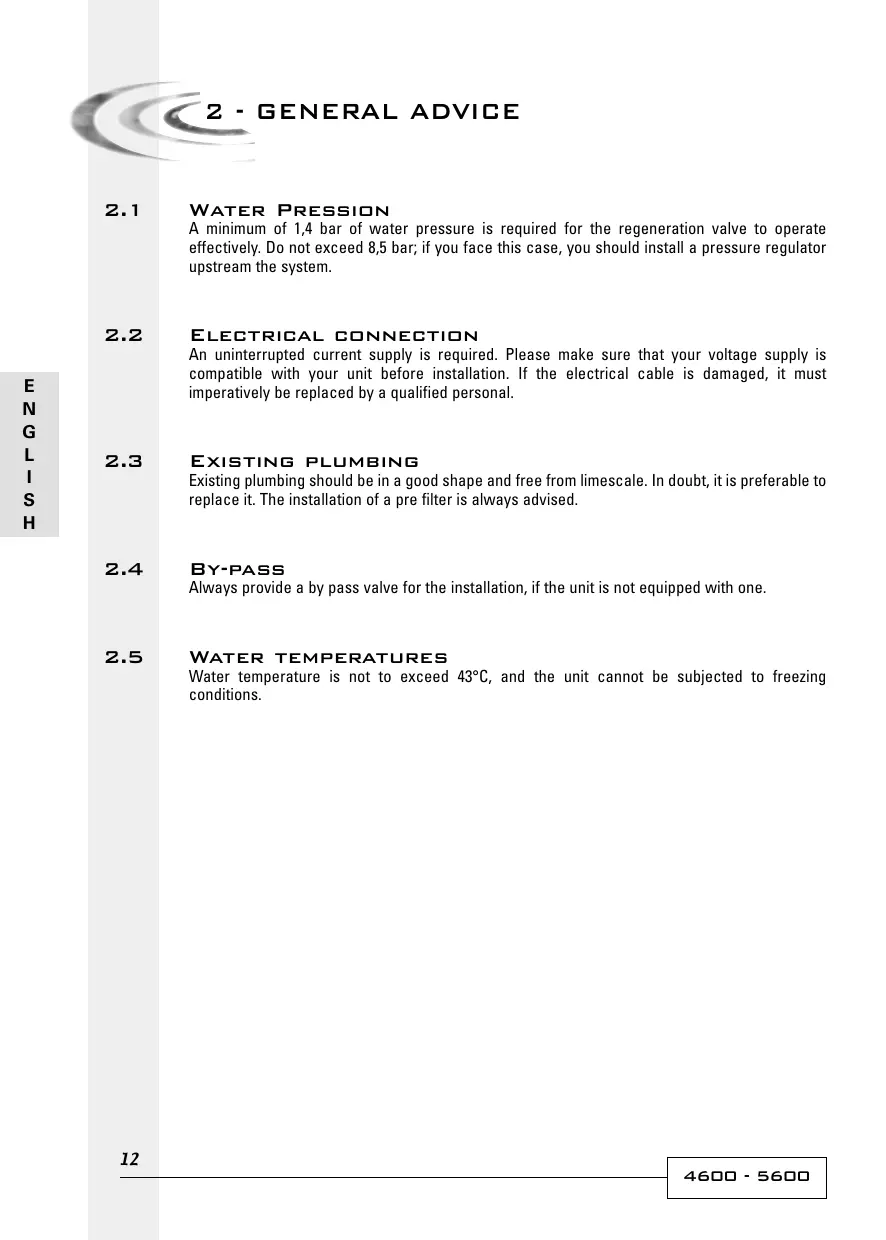
2.1 WATER PRESSION
A minimum of 1,4 bar of water pressure is required for the regeneration valve to operate effectively. Do not exceed 8,5 bar; if you face this case, you should install a pressure regulator upstream the system.
2.2 ELECTRICAL CONNECTION
An uninterrupted current supply is required. Please make sure that your voltage supply is compatible with your unit before installation. If the electrical cable is damaged, it must imperatively be replaced by a qualified personal.
2.3 EXISTING PLUMBING
Existing plumbing should be in a good shape and free from limescale. In doubt, it is preferable to replace it. The installation of a pre filter is always advised.
2.4 BY-PASS
Always provide a by pass valve for the installation, if the unit is not equipped with one.
2.5 WATER TEMPERATURES
Water temperature is not to exceed 43^ , and the unit cannot be subjected to freezing conditions.
3.1
Install the softener pressure vessel(s) in a chosen place on a flat firm surface.
3.2
During cold weather, it is recommended to bring the valve back to room temperature before operating.
3.3
All plumbing for water inlet, distribution and drain lines should be done correctly in accordance with legislation in force at the time of installation. Install without tension or bending stresses.
3.4
The distribution tube should be cut flush with the top of the tank. Slightly bevel the ridge in order to avoid deterioration of the seal whilst fitting the valve.
3.5
Lubricate the distribution tube joint and the joint with a 100% Silicon lubricant. Never use other types of greases that may damage the valve.
3.6
All soldering on main plumbing and to the drain line should be done before fitting the valve. Failing to do so can generate irreversible damages.
3.7
Use Teflon® tape if necessary in order to seal between the drain fitting and the outlet flow control.
3.8
On units with by-pass, place in by-pass position. Turn on the main water supply. Open a cold water tap nearby and let run a few minutes or until the system is free from foreign material (usually solder) that may have resulted from the installation. Once clean, close the water tap.
3.9
Place the by-pass in service position and let water flow into the mineral tank. When water flow stops, slowly open a cold water tap nearby and let run until the air is purged from the unit.
3.10
Plug the valve to a power source. Check that the valve is in service position
3.11
Fill approximately 25mm of water above the grid plate, (if used). Otherwise, fill to the top of the air check in the brine tank. Do not add salt to the brine tank at this time.
3.12
Initiate a manual regeneration, bring the valve into « brine draw and slow rinse position » in order to draw water from the brine tank until the blockage of the air check; the water level will be approximatively in the middle of the air check.
3.13
Open a cold water tap and let the water run in order to drain the air out of the circuit.
3.14
Bring the valve in brine refill position and let it get back to service position automatically.
3.15
Now you can add salt to the brine tank, the valve will operate automatically.
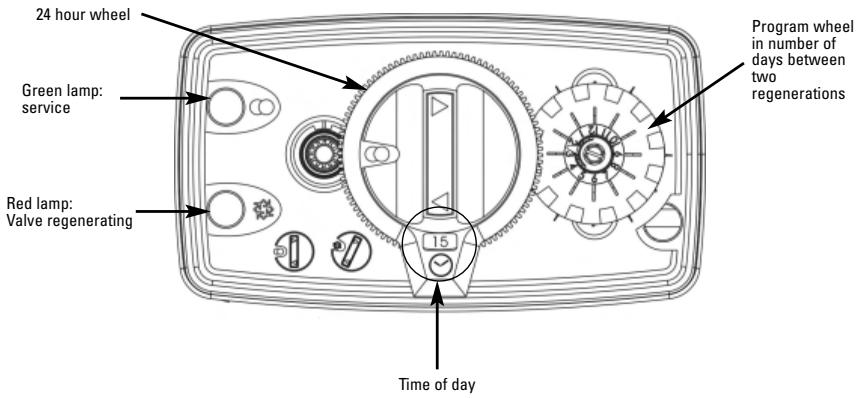
TIME CLOCK


LABEL SIGNIFICATION
Service

Regeneration

Backwash

Brine draw/ Slow rinse

Brine refill
METERED

White dot
Set the capacity of soft water between 2 regenerations using the following formula:
Water capacity in ^3 = exchange capacity in m^30tH - reserve capacity in ^3
Water hardness tH
To do so, lift the transparent disc with the label and display the capacity facing the white dot.
Example for the following drawing, the capacity set is 6.6 cubic meters between two regenerations.
TIME CLOCK
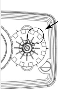
Pin pushed outside
Use the same formula as for metered version and divide by daily water consumption to obtain the number of days between 2 regenerations.
There are two time clock wheels:
- 7 days: based on the week, number 1 will refer to Monday, number 7 to Sunday.
- 12 days: allows to set a regular interval every 2, 3, 4, or 6 days.
To set up, push the pins out.
Example: on the drawing one regeneration every 2 days.
COMMON SETTINGS
Time of day
Press the clutch on the 24 hour wheel, red gear, then turn the hour wheel to display the correct hour in the window.
Salt volume per regeneration
Here is a table, usually used in water treatment.
| SALT WEIGHT
N G / LITRE OF RESIN | EXCHANGE CAPACITY
IN °TH / M2/ LITRE OF RESIN | SALT WEIGHT IN G / °TH / M2 |
| 80 | 4 | 20 |
| 125 | 5 | 25 |
| 180 | 6 | 30 |

On the brine cam, there is a segment and a indication Label in Kilogram. This segment with an indicator ensures the function of brine refill. Based on the table, set the amount of salt in Kg necessary for the resin regeneration. This way, the valve will send the correct volume of water in the brine tank in order to dissolve the necessary volume of salt for regeneration.
Example: 15 litres of resin x 125g = 1875g (1.9 kg of salt)
Place the indicator slightly under 2kg
| INCIDENT | CAUSE | SOLUTION |
| 1. Softener fails to regenerate | A. Interrupted powerB. Defective power headC. Unplugged meter cableD.Blocked meterE. Defective motorF. Wrong programming | A. Restore electrics (mains, fuse)B. Change power headC. Check connections of the time rand on the meter cover.D. Clean or change meterE. Change motorF. Check programming and modify if necessary |
| 2. Softener delivers hard water | A. By-pass in "by-pass" positionB. No salt in the brine tankC.Blocked injector and/or filterD. Not enough water in the brine tankE. Hardness arriving from hot water supplyF. Leak at the distributor tubeG. Internal valve leakH.Blocked meterI. Meter cable unpluggedJ. Wrong programming | A. Put by pass in "service" positionB. Add salt in the brine tank and keep salt level above water levelC. Clean or replace litre or injectorD. Check brine tank filling time and clean flow regulatorE. Repeated flushing of the hot water tankF. Ensure the distributor tube has no cracks, Check the O'ringG. Change seals & spacers and/or pistonH. Unblock the meterI. Check cable connections in the power head and on the meter coverJ. Check programming and modify if necessary |
| 3. Excessive salt consumption | A. Improper brine refill settingB. Too much water in the brine tankC. Wrong programming | A. Check use of salt and setting of brine refill.B. See problem n°6C. Check programming and modify if necessary |
| 4. Water pressure drop | A. Iron deposit in the softener inletB. Iron deposit in the softenerC. Valve inlet obstructed by foreign elements | A. Clean the inletB. Clean valve and resinC. Remove piston and clean valve |
| 5. Loss of resin through drain line | A. Top distributor missing or brokenB. Air in water systemC. Drain line flow control is the wrong size | A. Add or replace the top distributorB. Ensure the presence of air check system in the brine tankC. Ensure the drain line flow control is sized correctly |
| 6. Iron presence in softener | A. The resin bed is dirtyB. Iron concentration exceeds recommended parameters | A. Check backwash, brine draw and brine refill. Regenerate more often and increase backwash cycle timeB. Contact dealer |
| 7. Too much water in the brine tank | A. Plugged drain line flow control (DLFC)B. Faulty brine valveC. Wrong programming | A. Check flow regulatorB. Change brine valveC. Check programming and modify if necessary |
| 8. Salted water in in service line | A. Filter and injector blockedB. Power head not operating proper cyclesC. Foreign elements in brine valveD. Foreign elements in the brine line flow control (BLFC)E. Low water pressureF. Wrong programming | A. Clean injector and filterB. Change power headC. Change brine valve seat and clean itD. Clean BLFCE. Raise inlet pressure to 1,8 bar minimumF. Check programming and modify if necessary |
| 9. No brine draw | A. Plugged drain line flow control (DLFC)B. Plugged filter and injectorsC. Low water pressureD. Internal valve leakE. Wrong programmingF. Power head not operating properly | A. Clean drain line flow controlB. Clean filter and injector, change if necessaryC. Increase inlet pressure to 1,8 bar minimumD. Change seals, spacers and/or piston assemblyE. Check programming and modify if necessaryF. Change power head |
| 10. The valve regenerates constantly | A. Faulty power headB. Faulty microswitch or wiring loomC. Defective or badly set cycle cam | A. Change power headB. Change microswitch or wiring loomC. Reposition or change cycle cam |
| 11. Constant leakage to the drain | A. Foreign elements in the valveB. Internal valve leakC. Valve blocked in brine refill or backwashD. Defective or blocked timer motorE. Powerhead not operating properly | A. Clean valve and check it in the different regeneration positionsB. Change seals & spacers and/or piston assemblyC. Change seals & spacers and/or piston assemblyD. Change motor and check gear teethE. Change power head |
OPTIONS
Hot water available only on the 4600 valve:
The use of specific materials allows the valve to work at temperatures higher than 43^ : Up to 82^ for a timeclock version or 65^ for a metered version.
As opposed to time clock or metered valves that regenerate at 2 A.M. this option allows the valve to regenerate immediately after the set capacity is consumed
Fast Regeneration (FR):
This option allows the valve to regenerate in 90 minutes instead of 180 minutes. This valve can only be fitted with vessels up to 10^ .
Low water usage piston (L.W.U.):
With this piston, water consumption during regeneration can be reduced.
Pistone LWU (Low Water Usage = pistone economico):
Drain line flow control (DLFC)
GPM
Brine line flow control (BLFC)
GPM
Specific part assembly for the 4600 Hot water version
Assembly according to timeclock or metered version
Performances results available upon request