
OCTAPAD SPD-30 - Electronic drum ROLAND - Free user manual and instructions
Find the device manual for free OCTAPAD SPD-30 ROLAND in PDF.
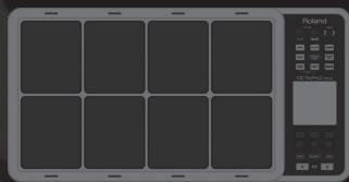
| Product type | Electronic percussion pad |
| Brand | Roland |
| Model | OCTAPAD SPD-30 |
| Number of pads | 9 pads (8 main + 1 external pad) |
| Dimensions | 302 x 273 x 63 mm |
| Weight | 2.1 kg |
| Power supply | AC adapter (DC 9 V) or 6 AA batteries |
| Battery life | Approximately 6 hours |
| Built-in sounds | Over 300 sounds and drum kits |
| Effects | Reverb, delay, flanger, etc. |
| Metronome | Integrated with tempo and time signature settings |
| Connectivity | Headphone output, stereo outputs (L/MONO, R), input for additional pad, MIDI IN/OUT, USB |
| USB function | Data transfer and MIDI to computer |
| MIDI function | Control of external modules and sequencers |
| Internal memory | Recording of patterns and user kits |
| Display | Backlit LCD screen |
| Care and cleaning | Wipe with a soft dry cloth. Do not use solvents. |
| Safety | Do not expose to moisture, shocks, or extreme temperatures. |
| Spare parts and repairability | Contact a Roland authorized service center. |
Frequently Asked Questions - OCTAPAD SPD-30 ROLAND
User questions about OCTAPAD SPD-30 ROLAND
0 question about this device. Answer the ones you know or ask your own.
Ask a new question about this device
Download the instructions for your Electronic drum in PDF format for free! Find your manual OCTAPAD SPD-30 - ROLAND and take your electronic device back in hand. On this page are published all the documents necessary for the use of your device. OCTAPAD SPD-30 by ROLAND.
USER MANUAL OCTAPAD SPD-30 ROLAND
OCTAPAD
SPD-30
Owner's Manual
For the U.K.
IMPORTANT: THE WIRES IN THIS MAINS LEAD ARE COLOURED IN ACCORDANCE WITH THE FOLLOWING CODE.
BLUE: NEUTRAL
BROWN: LIVE
As the colours of the wires in the mains lead of this apparatus may not correspond with the coloured markings identifying the terminals in your plug, proceed as follows:
The wire which is coloured BLUE must be connected to the terminal which is marked with the letter N or coloured BLACK. The wire which is coloured BROWN must be connected to the terminal which is marked with the letter L or coloured RED. Under no circumstances must either of the above wires be connected to the earth terminal of a three pin plug.
The OCTAPAD Legend
1985 was the year that Roland's revolutionary percussion instrument was announced — the "OCTAPAD" (PAD-8). A totally unique percussion instrument, the OCTAPAD allowed one to perform on the 8 pads, and via MIDI, control a drum machine (like the TR-909) or an external MIDI module or sampler. This instrument was immediately adopted by musicians around the world, not only for playing drum or percussion sounds, but also using it to perform all styles of music.
1988 saw the release of the "OCTAPAD II" (PAD-80), which not only maintained the exciting features of the first-generation OCTAPAD, but added many new ones like Layering and pedal control.
1990–1998 was the era when musicians used either of the first-generation OCTAPADs. As they did not have an on-board sounds, most of the time they were connected to drum machines, (TR-909, R-8 etc) So In 1990, Roland introduced the SPD-8 which had its own on-board sound source.
In 1993, It was followed by the SPD-11 which not only had more sounds but also built-in effects processing.
And then in 1998, the legendary SPD-20 appeared on the scene. Which featured a major enhancement to its sounds.
So throughout the years, the SPD series continued to evolve. And even though the instrument was called and SPD-8/11/20, most people will referred to it as an OCTAPAD.
2010 marks the comeback of the new OCTAPAD (SPD-30) for the 21st century. While maintaining the basic design of the precedent models, this new OCTAPAD features a large display, a friendly user interface, cutting-edge sounds, effects, USB MIDI and the latest pad sensing technology developed for the V-drums series.
The most exciting and evolutionary step of the new OCTAPAD is its “Phrase Loop function” which allows you to turn your inspiration into sound; meaning you can create your own rhythm loops, and layer your performance on top, all in real time.
That alone enhances the potential of the 8 pads on board, and expands the playable combination of percussion instruments.
The quarter-century legend of the OCTAPAD continues.
Turning the Power On/Off 6
Overview 7
01 Overview of the OCTAPAD 8
What is an Inst? 8
What is a Kit? 8
What are Ambience and FX?......9
What is a Phrase Loop?......9
Editing and Saving Your Data....9
02 Panel Descriptions....10
Top Panel 10
Rear Panel Connections 12
03 Displays and Operations .....14
KIT Screen 14
QUICK MENU Screens 15
MENU Screen 16
PHRASE LOOP Screen 18
04 FACTORY RESET ....20
Basic Operation 21
01 Selecting a Kit....22
[KIT] Buttons....22
KIT LIST 22
FAVORITE KITS....22
KIT CHAIN Function 22
Foot Switch....22
02 Selecting an Inst (INST) .....23
03 MULTI EDIT....24
04 Effects Editing (AMBIENCE and FX)....25
AMBIENCE 25
FX 25
05 Recording a Phrase Loop (PHRASE LOOP) ....26
Step 1: Select a Kit....26
Step 2: Make Settings Before Recording....26
Step 3: Recording 27
Re-doing the Recording 28
Erasing a Track (ERASE)....28
Undoing a Recording (UNDO) 28
Clearing the Phrase (CLEAR PHRASE) ..... 28
Saving the Phrase (SAVE PHRASE)....28
Exiting Phrase Loop Mode....28
Advance Operation 1 (Kit) 30
Creating a Kit ....30
Inst Settings (INST) 30
Inst and Layer Settings (INST-INST) 30
Editing an Inst (INST-EDIT)....31
Hi-hat Settings (INST-HH CTRL) 32
INST Screen QUICK MENU 33
Settings for the Entire Kit (KIT OTHERS)....34
Kit Volume, Tempo, and Protect (KIT OTHERS-KIT) 34
Phrase Settings Recalled by the Kit (KIT OTHERS-PHRASE)....34
Assigning a Name (NAME) 35
NAME Palette QUICK MENU 35
Copying a Kit or Pad (COPY) 35
Copying a Pad 35
Copying a Kit 36
Exchanging Pads (PAD EXCHANGE) 36
KIT CHAIN ....37
Creating a Kit Chain (KIT CHAIN) 37
KIT CHAIN Screen QUICK MENU ....37
Switching Kit Chains....38
Using the Effects (FX)....39
FX Settings (FX) 39
Switching the FX Type (FX-TYPE)....39
Editing FX Parameters (FX-EDIT) 39
Setting the FX Send Level for Each Pad (FX-SEND) 40
FX Screen QUICK MENU 40
Copying FX Settings....40
Using the Knobs to Control the FX (FX CONTROL) ... 41
Editing the AMBIENCE....42
Ambience Settings (AMBIENCE-AMBIENCE) ..... 42
Equalizer Settings (AMBIENCE-EQ)....42
Limiter Settings (AMBIENCE-LIMIT) 42
Advanced Operation 2 (Phrase Loop) ^43
Creating a Phrase ....43
Measures, Time Signature (Beat) and Metronome (Click) Sound Settings (SETUP)....43 Using the [SET LOOP] Button to Set the Loop Point....43
Quantize and Tempo Settings (STANDBY) .... 44 STANDBY Screen QUICK MENU .... 44 Switching the Part's Kit (STANDBY) .... 44
Recording a Phrase (REC Mode)....45 Performing Along with a Recorded Phrase (PLAY Mode)....45 REC/PLAY Screen QUICK MENU....45 Stopping the Phrase (STOP)....45
Editing a Phrase....46 What You can do in REC/PLAY Mode....46
Muting a Track (MUTE)....46 Erasing a Track (ERASE)....47 Reserving the Operation at the Next Loop (NEXT)...47 Adjusting the Volume of Each Part (PART LEVEL)....48 Exiting Phrase Loop Mode....48
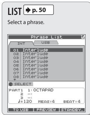
Saving/Loading a Phrase ....49 Saving a Phrase (SAVE PHRASE)....49 Loading a Phrase (PHRASE LIST)....50 PHRASE LIST Screen QUICK MENU....50
Phrase Loop and Metronome (Click) Sound Settings ....51 Phrase Loop Settings (PHRASE LOOP SETUP) ....51 Metronome (Click) Sound Settings (PHRASE LOOP SETUP-CLICK) ....51
Advanced Operation 3 (Other Settings) 52
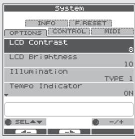
Settings for the Entire OCTAPAD (SYSTEM)....52 Screen and Illumination Settings (SYSTEM-OPTIONS) 52 Foot Switch and External Pad Settings (SYSTEM-CONTROL)....53 Connecting Foot Switches ....53 Viewing Information About the System (SYSTEM-INFO)....54
Using USB Memory....55 Formatting USB Memory (USB-FORMAT)....55 Saving Data to USB Memory (USB-SAVE)....56 Loading Data from USB Memory (USB-LOAD)....56 Viewing or Deleting USB Memory Data (USB-VIEW).57
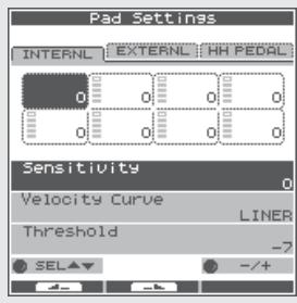
Connecting to your Computer via USB....58 Internal Pad Sensitivity Settings ....59 Internal Pad Settings (PAD SETTING-INTERNAL)....59
External Pad and Pedal Settings....60 Connecting Optional Pads or Pedals ....60 External Pad Settings (PAD SETTING-EXTERNAL)....60 Specifying the External Pad Type (PAD TYPE) ....61 Adjusting the External Pad Sensitivity ....61 External Hi-Hat Pedal Settings (PAD SETTING-HH PEDAL)....62 VH-11 Offset Adjustment....62
MIDI Settings ....63 MIDI Settings for a Kit (KIT MIDI) ....63 KIT MIDI Screen QUICK MENU ....64 System MIDI Settings (SYSTEM-MIDI)....65
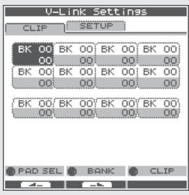
Using V-LINK to Control Images ....66 V-LINK Settings (V-LINK SETTINGS)....66 Turning V-LINK On/Off....66
Appendix 67
Error Message List....68 Specifications....68 Troubleshooting....69
Attaching the Stand (Sold Separately)....69 MIDI Implementation Chart....70 USING THE UNIT SAFELY....72
IMPORTANT NOTES....73 Index....74
Turning the Power On/Off
NOTE
Once the connections have been completed (p. 12), turn on power to your various devices in the order specified. By turning on devices in the wrong order, you risk causing malfunction and/or damage to amplified speakers (which we'll simply call "speakers") and other devices.
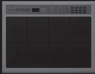
- Lower the volume of the OCTAPAD and amplification system.

Turn the [PHONES] and [MASTER] knob all the way to the left.
- Press the [POWER] button.

The OCTAPAD is equipped with a protection circuit. A brief interval (a few seconds) after power up is required before the unit will operate normally.
-
Turn on the power of your speakers.
-
Adjust the volume.

While playing the pads of the OCTAPAD, slowly turn the [MASTER] knob toward the right, and set the volume on the OCTAPAD and speakers.
Use the [PHONES] knob to adjust the volume of the headphones.
MEMO
Adjust your speaker system so that the volume is appropriate when the [MASTER] knob is approximately at the 3 o'clock position as shown in the illustration. Turn the knob toward the right to increase the volume, or toward the left to decrease it.

Turning the Power Off
- Minimize the volume of the OCTAPAD and your speakers.
- Turn off the power of your speakers.
- Hold down the [POWER] button until the display indicates "See you!"
Be sure to use the [POWER] button to turn off the power!
NOTE
The OCTAPAD automatically saves data during the power-down process. If power is turned off by unplugging the AC adaptor or power cable, data will NOT be saved, and malfunctions may occur.
Overview
Welcome to the world of the OCTAPAD.
This chapter provides an overall explanation of the OCTAPAD. Whether you are a beginner or an experienced user of electronic musical equipment, reading this chapter will help you save time and learn to operate the OCTAPAD smoothly.
What is an Inst?
All the sounds and instruments on board the OCTAPAD are referred to as "INST."
natural_image
Illustration of a vintage camera setup with a tripod-mounted dish and a control panel (no text or symbols visible)What is does Layer mean?
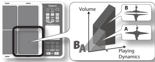
Two Insts (Inst A, Inst B) can be assigned to each pad.
"Inst Layer Type" (p. 30) lets you choose how the Layer function will operate. The layered sounds can be mixed equally, or can be controlled by playing dynamics. With a hi-hat for example, by playing softly you can have the closed hi-hat sound, and when playing harder, the open hi-hat sound (p. 33). Or you can use a snare drum sound, so when play softly you hear the head sound, and when playing louder you can have a rim shot.
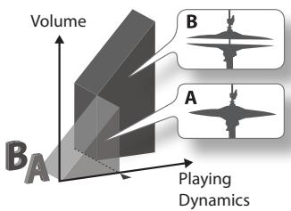
When the layer type is "SWITCH"
When the layer type is "FADE"
What is a Kit?
All instruments assigned to the eight pads and four external pads (p. 60) as well as the effects used, are memorized as a "Kit." You can select kits by pressing the [KIT] buttons (or foot-switches).
In live performance situations, the Kit Chain function allows you to determine the switching order of selected kits. See p. 37. Also there is a Favorite function, giving you quick access to your favorite kits. See p. 22.
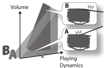
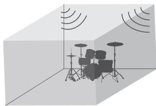
What are Ambience and FX?
The "Ambience" selected is a global function, meaning that all kits will use this effect. You can select from various types of rooms and halls.
"FX" is a full blown effects unit that can be used on an individual kit basis.
natural_image
3D-rendered room with a drum set, microphones, and sound waves (no text or symbols)Ambience
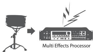
FX
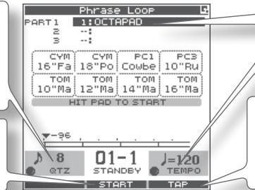
What is a Phrase Loop?
The Phrase Loop function is a recording feature that allows you to loop record something in real time, and then overdub on top. The potential is very exciting for live performances.
As each phrase has three “parts” it means, for example, that you can record a 16-beat phrase on part 1, some Latin percussion on part 2, and a either record or just perform a melodic percussion kit on top. It’s almost like having three OCTAPADs!
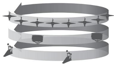
natural_image
Abstract diagram of a spiral structure with star-like elements and human figures at base (no text or symbols)Editing and Saving Your Data
The OCTAPAD features some powerful editing tools such as tuning, muffling, tone color etc. Also, the FX for each kit can be edited as well. This allows you to really personalize your sound.
All of your edits are automatically saved internally. If you need to, you can restore an individual kit to the factory settings. See "04 FACTORY RESET" (p. 20).
You can also use a USB memory (sold separately) to save your data. See p. 56.
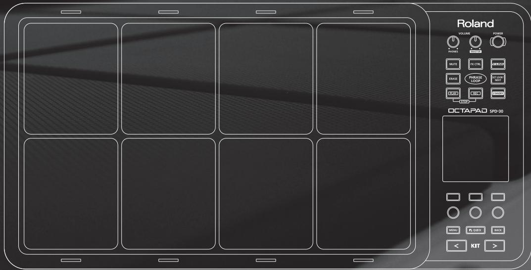
Top Panel
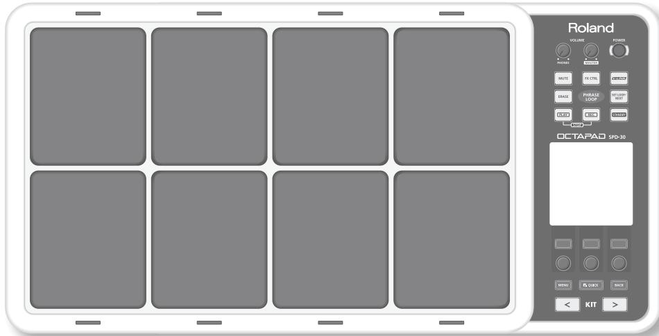
Display, Buttons & Knobs
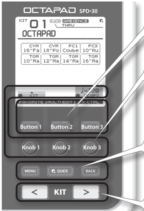
Function button 1–3
These buttons (from left to right) [Button 1], [Button 2], and [Button 3] execute various functions indicated in the bottom of the display.
Function knob 1–3
These knobs (from left to right) [Knob 1], [Knob 2], and [Knob 3] correspond to functions indicated by a knob icon (☐) in the display.
[MENU] button
→ p. 16
To access the main menu screen.
[QUICK] button
p. 15
In screens that show a 📁 icon in the upper right, pressing this button will call up various choices relative to the screen you are in.
[BACK] button
This button returns to the previous screen or cancels an operation.
[KIT] buttons
→ p. 22
Use these back-lit buttons to switch kits. When editing, pressing these buttons will return you to the KIT screen.
* Be aware that the screen shots shown in this manual will not necessarily match the factory-set content shown in your screen (Kit names, Inst names, and Effect names).
* You may notice some inconsistency in the contrast of the display; this is not a malfunction. Adjust "LCD Contrast" (p. 52) appropriately to minimize the inconsistency in the display's contrast.
![ROLAND OCTAPAD SPD-30 - [KIT] buttons - 1](/content/2025/01/130963/images/9e1aa80dfc7b338d3067bdecae5ee557ebfc96ba28a5ed1ee603f737ecfa7bb6.jpg)
natural_image
Diagram of a grid layout with diagonal lines and control points, no text or symbols presentPad Status Illumination
The LED indicators can be helpful when playing on a dark stage. See "Illumination" (p. 52).
When using a Phrase Loop, they will show pad status (muted, erase, etc.)
Pad
Play them with sticks.
* Playing anything other than the pads can cause malfunctions.
Volume & Power
![[VOLUME/PHONES] knob ▶ p. 6 Adjusts the headphone volume. [RVOLUME/MASTER] knob ▶ p. 6 Adjusts the volume of the OUTPUT jacks. [POWER] button ▶ p. 6 For turning the power on/off. Roland VOLUME POWER PHONES MASTER](/content/2025/01/130963/images/8e115cbbe0c4acbb3f95f0dcf80246934836deb8ef52e2442b1e946766fe9587.jpg)
Phrase Loop area → p. 43
flowchart
graph TD
    A["MUTE"] --> B["PHYRASE LOOP"]
    C["FX CTRL"] --> B
    D["V2LINK"] --> B
    E["ERASE"] --> B
    F["SET LOOP/ NEXT"] --> B
    G["PLAY"] --> H["STOP"]
    I["REC"] --> H
    J["STANDBY"] --> H
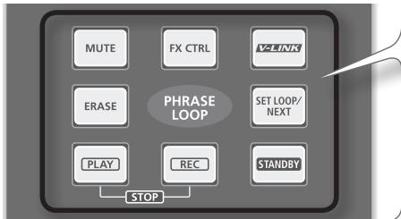
[STANDBY] button ➤ p. 43
For entering Phrase Loop mode. The Setup screen appears while holding down this button, and you can use the pads to select the number of measures.
[PLAY]/[REC] ([STOP]) button ➤ p. 45
These buttons switch between recording (overdubbing) and playing the Phrase Loop. You can stop the phrase by pressing the [PLAY]/[REC] buttons simultaneously.
[MUTE] button ➤ p. 46
While holding down this button and hitting a pad, you can mute or un-mute the corresponding track.
Mute status is shown in the display and by the pad's illumination.
[ERASE] button ➤ p. 47
While holding down this button and hitting a pad, you can erase a specific portion of a track. Hit the pad at the moment you want to start erasing, and once again when you want to stop. Erase status is shown in the display and by the pad's illumination.
[FX CTRL] button ➤ p. 41
Press this button to access a screen allowing you to use the knobs to control effects. While in Phrase Loop record mode, these knob movements will be recorded.
[SET LOOP/NEXT] button ➤ p. 47
When this button is blinking, you can set the loop point (p. 43).
When this button is lit, it is for reserving the operation (MUTE/PLAY/REC/STOP) that will occur at the beginning of the next loop (p. 47).
[V-LINK] button ➤ p. 66
Pushing this button selects V-LINK mode, allowing you to control video devices in real time.
This button will function even when not in Phrase Loop Mode.
This blinks in time with tempo. To turn this function off, see "Tempo Indicator" (p. 52).
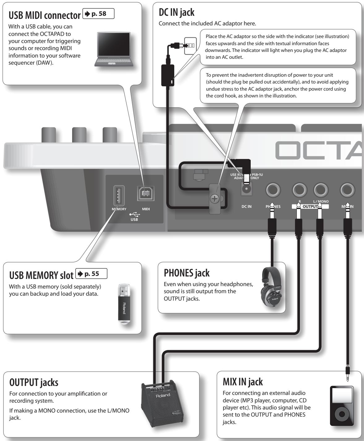
Rear Panel Connections
flowchart
graph TD
    A["USB MIDI connector"] -->|p. 58| B["USB MEMORY slot"]
    B --> C["OUTPUT jacks"]
    C --> D["MIX IN jack"]
    D --> E["PHONES jack"]
    E --> F["DC IN"]
    F --> G["DC IN jack"]
    G --> H["USB ROLL & PSB-1U ADAP ONLY"]
    H --> I["USE ROLL & PSB-1U ADAP ONLY"]
    I --> J["Place the AC adaptor so the side with the indicator (see illustration) faces upwards and the side with textual information faces downwards. The indicator will light when you plug the AC adaptor into an AC outlet."]
    I --> K["To prevent the inadvertent disruption of power to your unit (should the plug be pulled out accidentally), and to avoid applying undue stress to the AC adaptor jack, anchor the power cord using the cord hook, as shown in the illustration."]
    L["USB MIDI connection"] --> M["USB memory cable, you can connect the OCTAPAD to your computer for triggering sounds or recording MIDI information to your software sequencer (DAW)."]
    N["DC IN jack"] --> O["USE ROLL & PSB-1U ADAP ONLY"]
    P["USB MEMORY slot"] --> Q["USB MEMORY slot p. 55"]
    R["OUTPUT jacks"] --> S["For connection to your amplification or recording system. If making a MONO connection, use the L/MONO jack."]
    T["MIX IN jack"] --> U["For connecting an external audio device (MP3 player, computer, CD player etc). This audio signal will be sent to the OUTPUT and PHONES jacks."]
NOTE
- To prevent malfunction and/or damage to speakers or other devices, always turn down the volume, and turn off the power on all devices before making any connections.
- When connection cables with resistors are used, the volume level of equipment connected to the inputs (MIX IN) may be low. If this happens, use connection cables that do not contain resistors.
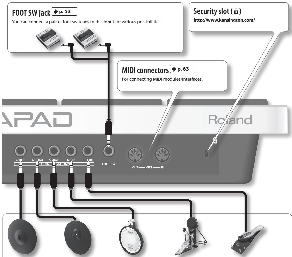
flowchart
graph TD
    A["FOOT SW jack"] -->|p. 53| B["MIDI connectors"]
    C["Security slot (@)"] -->|http://www.kensington.com/| D[" Roland "]
    E["Foot SW"] --> F["OUT—MIDI—IN"]
    G["4/RIDE"] --> H["TERNAI"]
    I["3/HH-HAT"] --> J["2/SNARE"]
    K["2/SNARE"] --> L["1/KICK"]
    M["1/KICK"] --> N["HH CTRL"]
    O["HH CTRL"] --> P["FOOT SW"]
    Q["FOOT SW"] --> R["OUT—MIDI—IN"]
    S["FOOT SW"] --> T["TERNAI"]
    U["TERNAI"] --> V["2/SNARE"]
    W["2/SNARE"] --> X["1/KICK"]
    Y["1/KICK"] --> Z["HH CTRL"]
    AA["HH CTRL"] --> AB["FOOT SW"]
| 4/RIDE | 3/HI-HAT | 2/SNARE | 1/KICK | HH CTRL |
| V-cymbal (e.g., CY-12R/C) | Cymbal pad (e.g., CY-5) | V-pad (e.g., entire PD series) | Kick trigger pad (e.g., KD-8, KD-7) | Hi-hat control pedal (FD-8, VH-11) |
EXTERNAL TRIGGER INPUT jacks
→ p. 60
Even though jacks 1–4 have specific indications, you can use them as you like. Make sure you use the respective cables (stereo) for dual trigger pads/cymbals. All these options are for products sold separately.
The HH CTRL jack is for using with compatible controllers such as an FD-8 or VH-11.
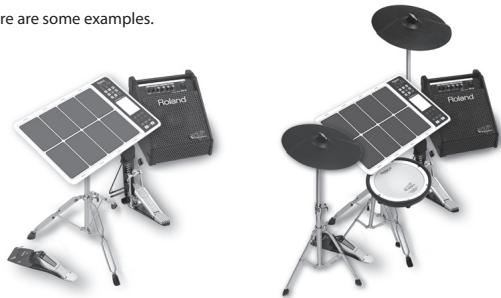
Connect optional pedals and pads
You can expand the possibilities of the OCTAPAD by connecting optional pedals and pads. This way you can play with your hands and feet.
Here are some examples.
natural_image
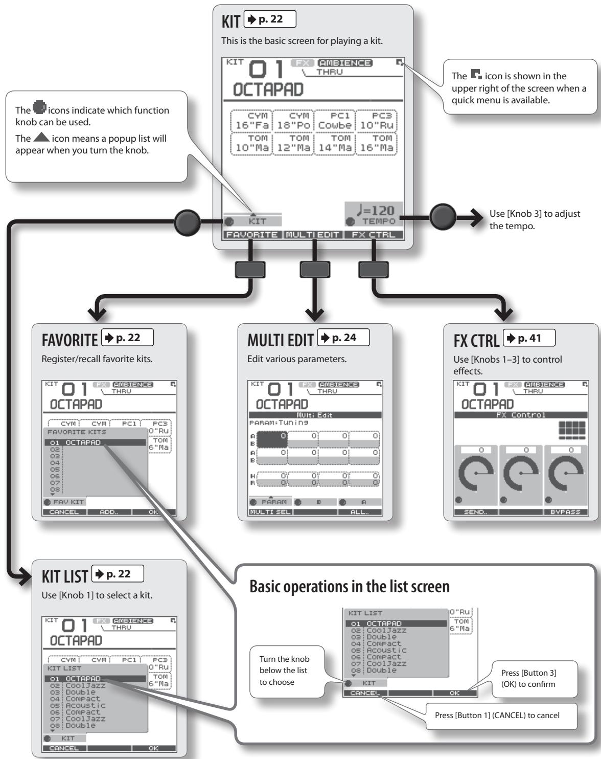
Two electronic music equipment setups: a solar panel and a Poland-branded cassette with two drums (no visible text or symbols)KIT Screen
The KIT screen is the basic screen that appears after powering up the OCTAPAD. The function buttons and knobs below the screen are used to navigate between screens. Press the [BACK] button to return to the KIT screen.
For details on each screen, refer to the indicated pages ➤ p.
flowchart
graph TD
    A["KIT"] --> B["This is the basic screen for playing a kit."]
    B --> C["The icon indicates which function knob can be used."]
    B --> D["The icon means a popup list will appear when you turn the knob."]
    B --> E["Use [Knob 3"] to adjust the tempo.]
    B --> F["FAVORITE"] --> G["Register/recall favorite kits."]
    B --> H["MULTI EDIT"] --> I["Edit various parameters."]
    B --> J["FX CTRL"] --> K["Use [Knobs 1-3"] to control effects.]
    B --> L["KIT LIST"] --> M["Use [Knob 1"] to select a kit.]
    B --> N["Basic operations in the list screen"]
    N --> O["Turn the knob below the list to choose"]
    N --> P["Press [Button 3"] (OK) to confirm]
    N --> Q["Press [Button 1"] (CANCEL) to cancel]
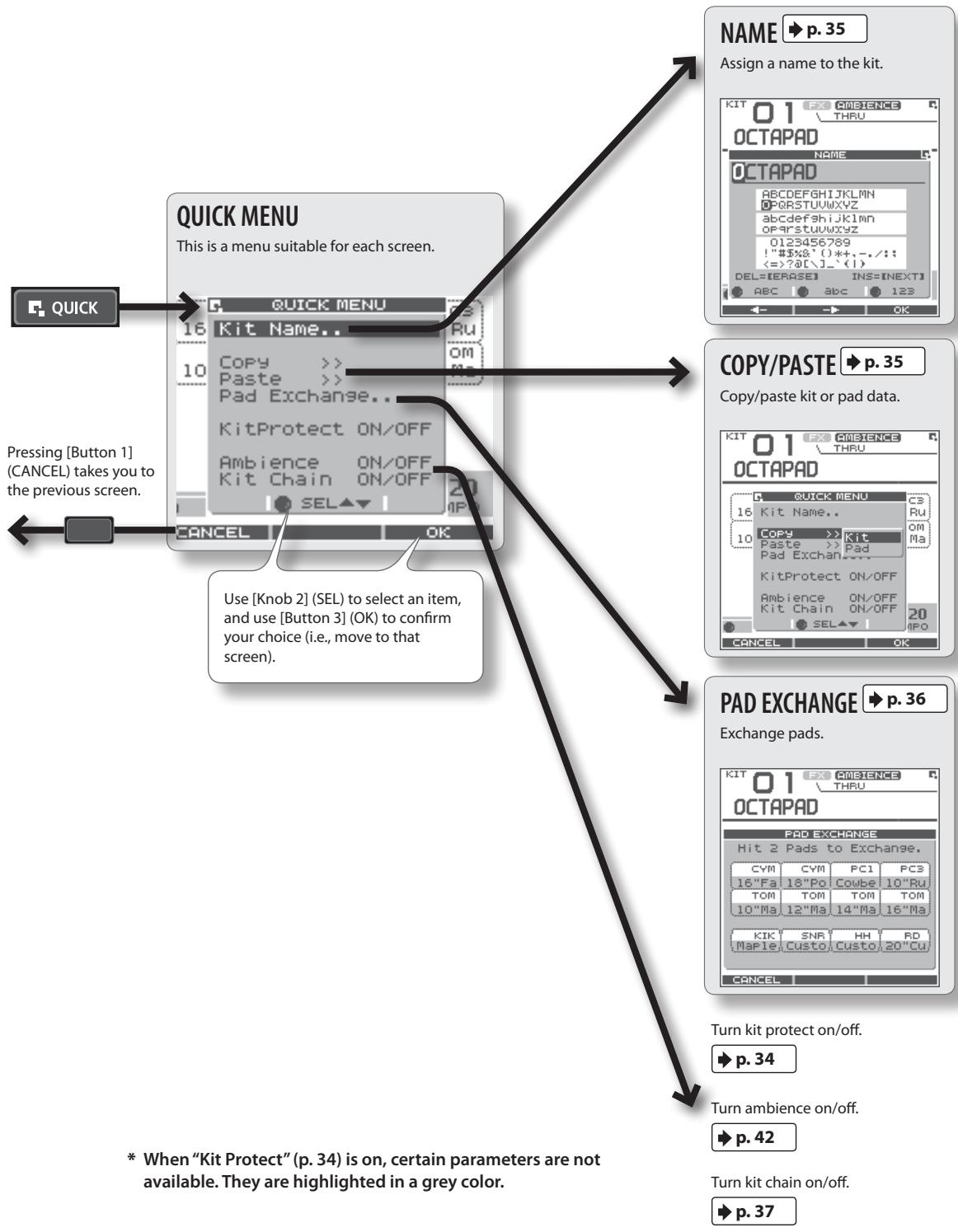
QUICK MENU Screens
When you see the 📁 icon in the upper right of the screen, pressing the [QUICK] button accesses the relative menu. We'll use the Quick Menu that appears in the KIT screen as an example.
In this manual, we'll use "QUICK MENU → Kit Name" to refer to the operation of choosing Kit Name from the QUICK MENU.
flowchart
graph TD
    A["QUICK"] --> B["QUICK MENU"]
    B --> C["16 Kit Name.."]
    C --> D["10 Copy >>"]
    D --> E["Paste >>"]
    E --> F["Pad Exchange.."]
    F --> G["KitProtect ON/OFF"]
    G --> H["Ambience ON/OFF"]
    H --> I["Kit Chain ON/OFF"]
    I --> J["OK"]
    J --> K["CANCEL"]
    K --> L["OK"]

    M["NAME"] --> N["p. 35"]
    N --> O["Assign a name to the kit."]

    P["COPY/PASTE"] --> Q["p. 35"]
    Q --> R["Copy/paste kit or pad data."]

    S["PAD EXCHANGE"] --> T["p. 36"]
    T --> U["Exchange pads."]

    V["QUICK MENU"] --> W["16 Kit Name.."]
    W --> X["10 Copy >>"]
    X --> Y["Paste >>"]
    Y --> Z["Pad Exchange.."]
    Z --> AA["KitProtect ON/OFF"]
    AA --> AB["Ambience ON/OFF"]
    AB --> AC["Kit Chain ON/OFF"]
    AC --> AD["OK"]

    AE["QUICK"] --> AF["QUICK MENU"]
    AF --> AG["16 Kit Name.."]
    AG --> AH["10 Copy >>"]
    AH --> AI["Paste >>"]
    AI --> AJ["Pad Exchange.."]
    AJ --> AK["KitProtect ON/OFF"]
    AK --> AL["Ambience ON/OFF"]
    AL --> AM["Kit Chain ON/OFF"]
    AM --> AN["OK"]

    AO["QUICK"] --> AP["QUICK MENU"]
    AP --> AQ["16 Kit Name.."]
    AQ --> AR["10 Copy >>"]
    AR --> AS["Paste >>"]
    AS --> AT["Pad Exchange.."]
    AT --> AU["KitProtect ON/OFF"]
    AU --> AV["Ambience ON/OFF"]
    AV --> AW["Kit Chain ON/OFF"]
    AW --> AX["OK"]

    AY["QUICK"] --> AZ["QUICK MENU"]
    AZ --> BA["16 Kit Name.."]
    BA --> BB["10 Copy >>"]
    BB --> BC["Paste >>"]
    BC --> BD["Pad Exchange.."]
    BD --> BE["KitProtect ON/OFF"]
    BE --> BF["Ambience ON/OFF"]
    BF --> BG["Kit Chain ON/OFF"]
    BG --> BH["OK"]

    BI["QUICK"] --> BJ["QUICK MENU"]
    BJ --> BK["16 Kit Name.."]
    BK --> BL["10 Copy >>"]
    BL --> BM["Paste >>"]
    BM --> BN["Pad Exchange.."]
    BN --> BO["KitProtect ON/OFF"]
    BO --> BP["Ambience ON/OFF"]
    BP --> BQ["Kit Chain ON/OFF"]
    BQ --> BR["OK"]

    BS["QUICK"] --> BT["QUICK MENU"]
    BT --> BU["16 Kit Name.."]
    BU --> BV["10 Copy >>"]
    BV --> BW["Paste >>"]
    BW --> BX["Pad Exchange.."]
    BX --> BY["KitProtect ON/OFF"]
    BY --> BZ["Ambience ON/OFF"]
    BZ --> CA["Kit Chain ON/OFF"]
    CA --> CB["OK"]

    CC["PAD EXCHANGE"] --> DD["p. 36"]
    DD --> DP["Exchange pads."]

    EQ["TURNIT PROTECT ON/OFF"] --> R["p. 34"]

    SC["TURNIT AMBIENCE ON/OFF"] --> T["p. 42"]

    U["TURNIT KITCH ON/OFF"] --> V["p. 37"]
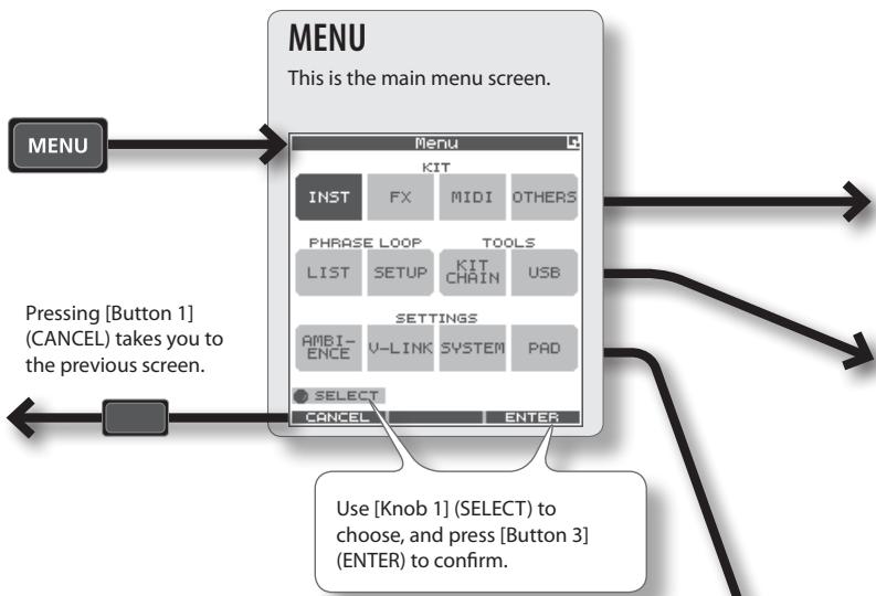
MENU Screen
Accessible from any screen pressing the [MENU] button takes you to the OCTAPAD's main menu.
In various explanations regarding the screens and menus, when you see, for example, "choose MENU → SYSTEM → F.RESET," the "→" points to the next selection you should make.
For details on each screen, refer to the pages listed on ➤ p.
flowchart
graph TD
    A["MENU"] --> B["Menu"]
    B --> C["KIT"]
    C --> D["INST"]
    C --> E["FX"]
    C --> F["MIDI"]
    C --> G["OTHERS"]
    B --> H["PHRASE LOOP"]
    H --> I["LIST"]
    H --> J["SETUP"]
    H --> K["TOOLS"]
    H --> L["KIT CHAIN"]
    H --> M["USB"]
    B --> N["SETTINGS"]
    N --> O["AMBI-ENCE"]
    N --> P["V-LINK"]
    N --> Q["SYSTEM"]
    N --> R["PAD"]
    B --> S["SELECT"]
    S --> T["CANCEL"]
    S --> U["ENTER"]
    B --> V["Pressing [Button 1"] (CANCEL) takes you to the previous screen.]
    V --> W["Use [Knob 1"] (SELECT) to choose, and_press["Button 3"] (ENTER) to confirm.]
KIT
PHRASE LOOP
Basic operations in each screen
![KIT 01 : OCTAPAD Inst INST EDIT HH CTRL Inst Layer Type Layer Point Inst A C#M 13 16 Fast CrBw Inst B Use [Knob 1] to select a parameter Use [Knob 3] to modify the value Use [Button 1] or [Button 2] to move to the tab, left or right](/content/2025/01/130963/images/a1e51dca7e945630456f99052fe6e94f9df0dd5b4fa0be1ed0b95c3bd73548a0.jpg)
* Press the [BACK] button to return to the previous screen.
Make ambience-related settings.
SETTINGS
AMBIENCE ➤ p. 42
MENU screen Quick Menu
If you press the MENU button and then press the [QUICK] button you will see "Force Save Data" in the pop-up window.
By pressing [Button 3] (OK) current data will be saved. (Also, The OCTAPAD will save your data automatically during the power-off process).

→ p. 39
Make effect (FX) settings.

→ p. 63
Make MIDI settings for the kit.

→ p. 34
Make other settings such as the kit's volume or tempo.

p. 51
Make phrase loop settings.
TOOLS

p. 37
Switch kits in an order you specify.
![Kit Chain A B C D E F G H BANK [A] NAME: Chain 1 STEP: 1 1:OCTAPAD 2 5:Acoustic 3 7:CoolJazz 4 --:(END) STEP -/+](/content/2025/01/130963/images/9e9a83028fd491c75cbb61dd04da16d1317be35f250c4e1be2e2b8274a055821.jpg)

p. 55
Save/load data on USB memory.
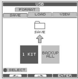
flowchart
graph TD
    A["SAVE"] --> B["1 KIT"]
    B --> C["BACKUP ALL"]
    D["SAVE"] --> E["1 KIT"]
    E --> F["BACKUP ALL"]

→ p. 66
Make V-LINK settings.

p. 52
Make system settings that apply to the entire OCTAPAD.

→ p. 59
Make pad-related settings such as pad sensitivity.
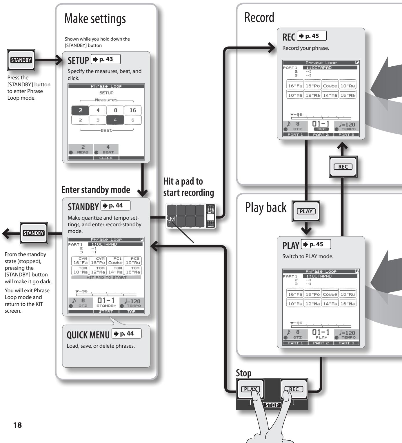
PHRASE LOOP Screen
Pressing the [STANDBY] button takes you to a page where you can set parameters of the phrase you are about to create.
For details on each screen, refer to the page references shown below ➤ p.
If you want to simply learn the operations, refer to "05 Recording a Phrase Loop (PHRASE LOOP)" (p. 26) in the Basic
Operation section.
flowchart
graph TD
    A["Make settings"] --> B["Enter standby mode"]
    B --> C["Play back"]
    C --> D["Stop"]
    D --> E["18"]

    subgraph Setup Settings
        F["STANDBY"] --> G["Press the [STANDBY"] button to enter Phrase Loop mode.]
        H["SETUP"] --> I["Specify the measures, beat, and click."]
        J["Phrase Loop"] --> K["Measures"]
        L["2 4 8 16"] --> M["2 3 4 6"]
        N["Beat"] --> O["2 MEAS BEAT CLICK"]
    end

    subgraph Record Settings
        P["RECACT"] --> Q["Record your phrase."]
        Q --> R["PLAY"]
        R --> S["Switch to PLAY mode."]
    end

    T["QUICK MENU"] --> U["Load, save, or delete phrases."]
    V["Make quantize and tempo settings, and enter record-standby mode."] --> W["Hit a pad to start recording"]
    X["Play back"] --> Y["PLAY"]
    Y --> Z["STOP"]
    Z --> AA["18"]
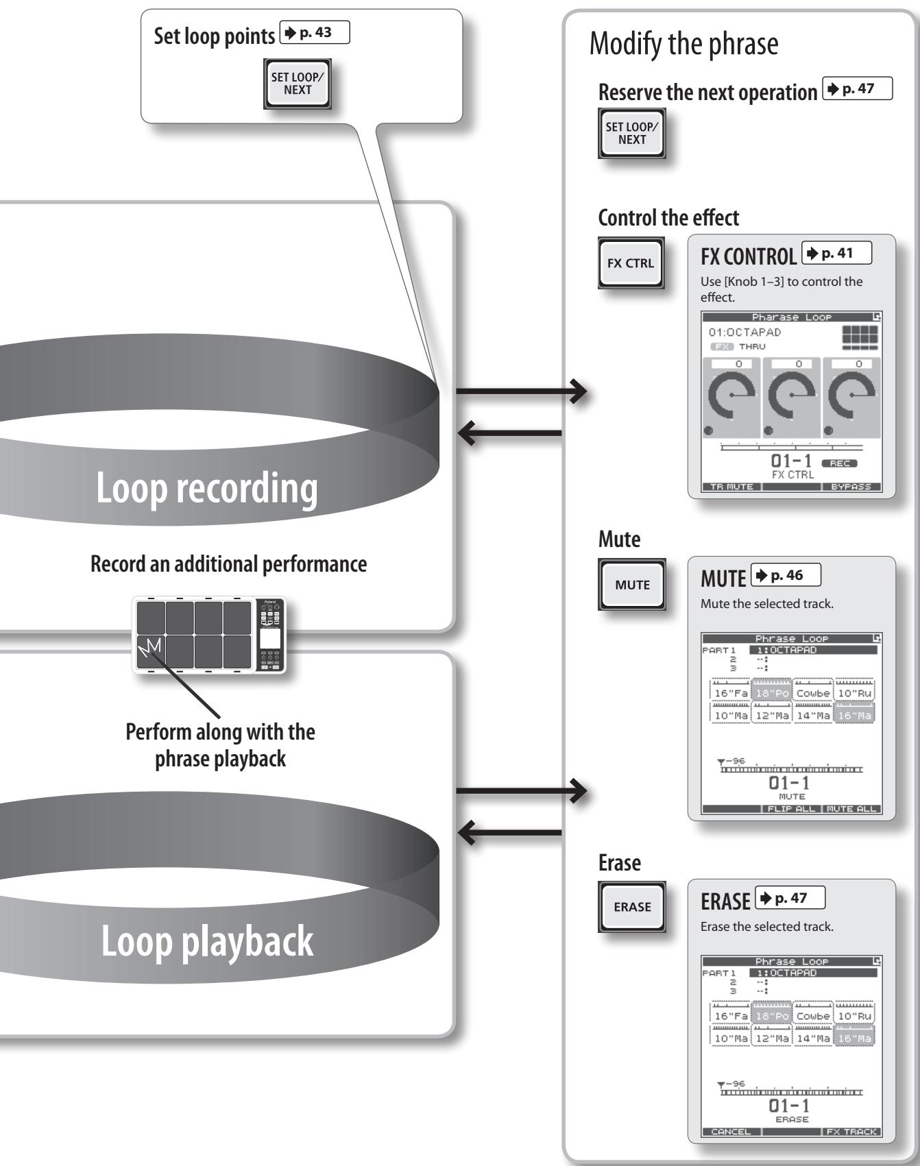
flowchart
graph TD
    A["Set loop points"] --> B["SET LOOP/ NEXT"]
    B --> C["Loop recording"]
    C --> D["Record an additional performance"]
    D --> E["Perform along with the phrase playback"]
    E --> F["Loop playback"]

    G["Modify the phrase"] --> H["RESERASE"]
    H --> I["Erase"]
    I --> J["ERASE"]

    K["Control the effect"] --> L["FX CTRL"]
    L --> M["FX CONTROL"]
    M --> N["Use [Knob 1-3"] to control the effect.]

    O["Mute"] --> P["MUTE"]
    P --> Q["MUTE"]
    Q --> R["MUTE"]

    S["Modify the phrase"] --> T["RESERASE"]
    T --> U["ERASE"]
    U --> V["ERASE"]

    W["Modify the phrase"] --> X["RESERASE"]
    X --> Y["ERASE"]

    Z["Control the effect"] --> AA["FX CTRL"]
    AA --> AB["FX CONTROL"]
    AB --> AC["Use [Knob 1-3"] to control the effect.]

    AD["Modify the phrase"] --> AE["RESERASE"]
    AE --> AF["ERASE"]
The restore function gives you a choice of restoring individual kits or all of them, all phrases, or a full Factory Reset.
NOTE
When you perform the Factory Reset operation, the kits and phrase data saved in the OCTAPAD will be initialized. If there's any data you want to keep, be sure to back it up to USB memory as described in "Saving Data to USB Memory (USB-SAVE)" (p. 56).
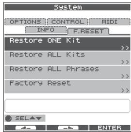
1. Choose MENU → SYSTEM → F.RESET.
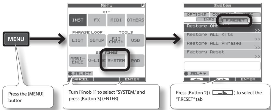
flowchart
graph TD
    A["MENU"] --> B["Menu"]
    B --> C["System"]
    C --> D["Press the [MENU"] button]
    B --> E["Turn [Knob 1"] to select "SYSTEM," and_press["Button 3"] (ENTER)]
    C --> F["Press [Button 2"] (—) to select the "F.RESET" tab]
2. Turn [Knob 1] (SEL) to the reset function and press [Button 3] (ENTER).
| Restore ONE Kit | Restore a specific kit |
| Restore ALL Kits | Restore all kits |
| Restore ALL Phrases | Restore all phrases |
| Factory Reset | Resets all data |
* When "Write Protect" (p. 52) is ON, restore and factory reset functions are not available. They are highlighted in grey.
3. Proceed as follows.
If you selected "Restore One Kit"
This function actually copies pre-set kit data stored in the OCTAPAD's internal memory.
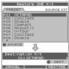
3-1. Use [Knob 1] (SOURCE) to select the source kit.
3-2. Use [Knob 3] (DEST) to select the destination kit.
3-3. Press [Button 3] (RESTORE) to execute.
- [Button 1] (CANCEL) will cancel the operation.
If you selected Restore All Kits/Phrases/Factory Reset
The following screen message will appear.
![Factory Reset ALL kits, Phrases and other settings will be lost. Press [RESTORE] to execute. Press [BACKUP] to save the data to the USB memory.](/content/2025/01/130963/images/3032c98dd5c4e48976d64d4efc09b78713847bb9c72e38063efd3db29af126e2.jpg)
3-1. Press [Button 3] (RESTORE or RESET) to execute.
- Press [Button 2] (BACKUP) to go to the USB-SAVE screen (p. 56).
- [Button 1] (CANCEL) will cancel the operation.
4. When the confirmation message appears, press [Button 3] (OK).
The reset will be executed. Never turn off the power during the reset process.
Basic Operation
It is important to understand the basic operations and functions of the OCTAPAD before using it. Please read this section fully as you check out the OCTAPAD'S possibilities.

Select any kit. The kit number and name appear in the KIT screen.
Information shown in the KIT screen

[KIT] Buttons
1. Use the backlit [KIT] buttons to switch kits.
The kit will change immediately, or if you are in any edit screen you will return to the current KIT.
By holding down either of the buttons, scrolling speed increases.

KIT LIST
1. In the KIT screen, turn [Knob 1] (KIT).
The KIT LIST appears. Turn the same [Knob 1] to move the cursor.
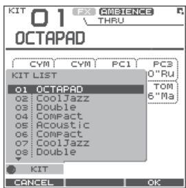
2. Press [Button 3] (OK) to select.
The kit will switch.
FAVORITE KITS
Here's how to register and recall your favorite kits.
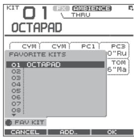
How to Register a favorite kit
- In the KIT screen, press [Button 1] (FAVORITE) and the list appears.
- Turn [Knob 1] (FAV KIT) to select the destination (10 possibilities).
- Press [Button 2] (ADD).
The "current" Kit you had selected before pressing the FAVORITE button will be assigned to your destination choice.
How to Recall a favorite kit
- In the KIT screen, press [Button 1] (FAVORITE) and the list appears.
- Use [Knob 1] (FAV KIT) to choose.
- Press [Button 3] (OK).
You'll switch to the kit that is selected in the list.
KIT CHAIN Function
The Kit Chain function allows you specify the order in which kits will switch. Very convenient for live performance.
For details, refer to "KIT CHAIN" (p. 37).
Foot Switch
Foot switches can be used to change kits.
For details, refer to "Foot Switch and External Pad Settings (SYSTEM-CONTROL)" (p. 53).

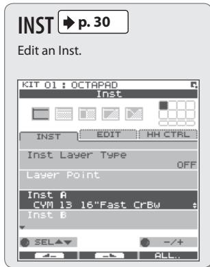
Here's how to change or assign an Inst to each pad. More about Insts and Layers is here: "What is an Inst?" (p. 8).
The changes you make here are saved. You can't modify a kit whose "Kit Protect" (p. 34) is on.
1. Choose MENU → INST → INST (p. 16).
The INST screen appears.
![Use [Knob 1] (SEL) to select a parameter. The cursor will Initially be at Inst A, so turning [Knob 3] (-/+) will change Inst A. KIT 01: OCTAPAD Inst INST EDIT HH CTRL Inst Layer Type OFF Layer Point Inst A CVM 13 16"Fast CrBw t Inst B SEL -/+ ALL... Indicates the pad you're currently editing and will change when you play any pad. Select Inst A. Select Inst B. (This will not work if Inst Layer Type is "OFF") Turn [Knob 3] (-/+) to modify the value.](/content/2025/01/130963/images/15baf2ae32715463f37792d001248de6c4ae24139063e00934ad85d51d0b71ee.jpg)
2. Play any pad whose Inst you want to change.
3. Turn [Knob 3] (-/+) to select an Inst.
![KIT 01: OCTAPAD INST INST EDIT HH CTRL INST GROUP:[KIK] 01 Maple K 02 Custom K 03 Birch K 04 Shallow K Inst Medium K 05 Studio K 06 Wood K 07 Soft K CNC Cancel PREVIEW OK Turn [Knob 2] (GROUP) to select the Inst group. Turn [Knob 3] (-/+) to select an Inst. Press [Button 3] (OK) to confirm the selected Inst.](/content/2025/01/130963/images/eb96adc8babc30709a066cd50d534ad46725257e0240a1e36a3f1f9eeeba9ee3.jpg)
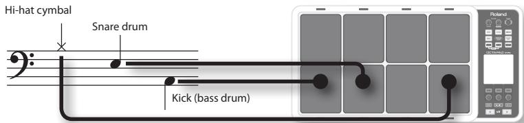
List of Inst groups
| KIK | Kick (bass drum) | PC1 | Percussion with heads |
| SNR | Snare drum | PC2 | Metallic percussion |
| TOM | Tom-tom | PC3 | Miscellaneous percussion |
| HH | Hi-hat cymbal | PC4 | Melodic percussion |
| RD | Ride cymbal | MEL | Pitched instruments |
| CYM | Crash cymbal | SFX | Sound effects |
| OFF | Off | ||
4. Repeat steps 2–3 to select the Inst for other pads.
5. Press the [BACK] button to return to the KIT screen.
Information on layer and other parameters, can be found here: "Inst Settings (INST)" (p. 30)
You can exchange data between the pads. Refer to "Exchanging Pads (PAD EXCHANGE)" (p. 36).
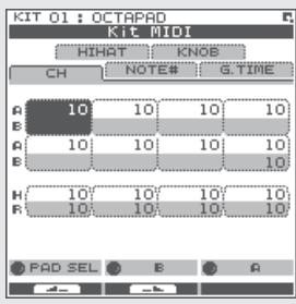
What is Multi Edit?
Pushing the Multi Edit button gives you access to 10 different editing parameters. (See the chart below)
1. In the KIT screen, press [Button 2] (MULTI EDIT).
The Multi Edit screen appears.
Here you can see all the relative values assigned to each pad and external trigger input.
The changes you make are saved in the kit. You can't edit a kit whose "Kit Protect" (p. 34) is on.
![Name of the parameter you're editing Turn [Knob 1] (PARAM) and a popup list appears select a parameter here. KIT O1 OCTAPAD Multi Edit Indicates the pad you're editing and will change when you play a pad. Value of each pad (Inst A is above, Inst B is below) Values for external trigger inputs 1–4 (Head is above, Rim is below) Use [Knob 2] (B) to change the value of Inst B (Rim). Use [Knob 3] (A) to change the value of Inst A (Head). Press [Button 3] (ALL) to copy the current value to all pads and external triggers.](/content/2025/01/130963/images/72cdb36cd08fa903a950235fb54a82357d73d00f13e8ef17e811f81fa3644c42.jpg)
2. Turn [Knob 1] (PARAM) to select the parameter and press [Button 3] (OK) to confirm your choice.
| Parameter | Value | Explanation |
| Tuning | -2400–+2400 | Negative (“-”) values will lower the pitch; positive (“+”) values will raise the pitch. The value will change in steps of 10 as you turn the knob. |
| Coarse Tune | -2400–+2400 | This is the same as Tuning, but the value will change in steps of 100 as you turn the knob. |
| Muffling | 0–50 | Increasing the value will decrease the resonance and decay. |
| Soft Attack | 0–50 | Specifies the sharpness of the attack. Increasing the value will soften the sound's attack. |
| Tone Color | L50–H50 | Modifies the brightness of the sound. Higher settings will produce a brighter sound. |
| Pitch Sweep | -100–+100 | Positive (“+”) settings will make the pitch change from high to low. Negative (“-”) settings will make the pitch change from low to high. |
| Volume | 0–100 | Specifies the volume. |
| Pan | L15–CTR–R15 | Specifies the pan position. CTR is center. |
| Reverse | OFF, ON | If this is ON, the pad's sound will play backward.* Some Insts will NOT play in reverse. |
| FX Send | 0–100 or OFF, ON | Determines the send level to FX (effect). Adjust accordingly. |
3. Hit a pad to select it for editing.
- If you want to edit multiple pads at the same time, hold down [Button 1] (MULTISEL) and play the desired pads.
- If you hit a pad that is not selected, it will cancel the multi selection.
To stay in this multi selection mode, only play the pads you have selected.
4. Use [Knob 3] (A) or [Knob 2] (B) to edit the value.
- [Knob 3] (A) changes the value for Inst A (Head).
- [Knob 2] (B) changes the value for Inst B (Rim).
5. Press the [BACK] button to return to the KIT screen.
If you want to adjust the pad's sensitivity, refer to "Internal Pad Sensitivity Settings" (p. 59).
For an overview of the effects, refer to "What are Ambience and FX?" (p. 9).
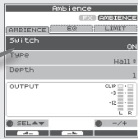
AMBIENCE
1. Choose MENU → AMBIENCE → AMBIENCE (p. 16).
The AMBIENCE screen appears. Use [Knob 1] and [Knob 3] to switch ambience on/off or change its type.
![Use [Knob 1] (SEL) to select a parameter. Ambience FX AMBIENCE AMBIENCE EQ LIMIT Switch ON Type Hall Depth 1 OUTPUT CLIP -3 -12 L R SEL +/- /+ Turns ambience on/off Ambience type Ambience depth Turn [Knob 3] (-/+) to edit the value.](/content/2025/01/130963/images/2f4e01f714e06a3869d8eff25300bae1ce226d96fafda214cd51c8f79ac57c13.jpg)
MEMO
In the KIT screen, you can also turn ambience on/off by using QUICK MENU → Ambience ON/OFF.
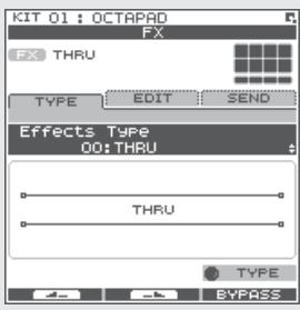
FX
1. Choose MENU → FX → TYPE (p. 16)
The FX screen appears. Use [Knob 3] to switch the FX type.
![KIT 01: OCTAPAD FX FX THRU TYPE EDIT SEND Effects Type 00:THRU THRU A diagram of the selected FX type will appear. Pad for which FX will apply FX type Use [Knob 3] (TYPE) to display the FX type list. [Button 3] (BYPASS) temporarily turns FX off. TYPE BYPASS](/content/2025/01/130963/images/7c114ac6d7f18e89fba9e98eab195eb11845eb182cf89cca23c1989e934368e9.jpg)
Using the knobs to control FX
1. Press the [FX CTRL] button.
The FX CONTROL screen appears. You can use [Knob 1]–[Knob 3] to control the FX parameters. The most suitable parameters for the effect will automatically be assigned to the knobs. Changes you make in the FX CONTROL screen are not saved to the kit.
![KIT 01 OCTAPAD FX CMBIENCE THRU FX type Pad for which FX is enabled Use [Button 1] (SEND) to move to a screen in which you can adjust each pad's send level. Use [Knob 1-3] to edit the effect parameters. [Button 3] (BYPASS) temporarily turns FX off. SEND.. BYPASS](/content/2025/01/130963/images/e50803cad326f1c7e5993f46a17b0c51365f9544c4539eac9812d327a3ab57cf.jpg)
For details on how to edit each parameter, refer to "AMBIENCE" (p. 42) and "FX" (p. 39).
To simply explain the Phrase Loop function we will use the basic 8-beat phrase shown below.
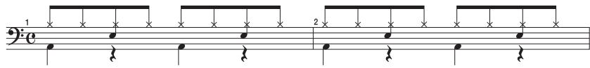
Step 1: Select a Kit
1. Use the [KIT] buttons to select the acoustic kit "50: Tutorial."
In kit "50: Tutorial," instruments are assigned to pads as follows. Start by practicing this phrase.
Step 2: Make Settings Before Recording
Measures, Time Signature (Beat) and Metronome (Click) Sound settings
Hold down the [STANDBY] button and the PHRASE LOOP SETUP screen appears.
![Phrase Loop SETUP Measures 2 4 8 16 2 3 4 6 Beat Press [Button 2] (CLICK); a bar appears above the button, and the click (Metronome) will start. The screen you will see here will indicate, in the top row, the length of the phrase (Measures). The time signature (Beat) is indicated in the lower row. 2 4 MEAS BEAT CLICK](/content/2025/01/130963/images/5f6005f8c418c3d6f989b9863ce38adf3561e9084ba4adc8e17a402e269ea5bd.jpg)
1. Hold down the [STANDBY] button and make your choice by hitting the relative pad or by turning [Knob 1] (MEAS) or [Knob 2] (BEAT).
As shown in the illustration, please select (2 measures, 4 beats) for this recording.
2. Press [Button 2] (CLICK).
You'll hear the click (Metronome).
MEMO
- The click sound can also be turned on/off from the PHRASE LOOP screen by choosing the Quick Menu "Click ON/OFF" command.
- The blinking tempo indicator (PHRASS LOOP) also shows the rhythm. If you don't want to hear a click (such as in a live performance), you can turn off the click sound and record while watching the blinking tempo indicator.
- As described in "Metronome (Click) Sound Settings (PHRASE LOOP SETUP-CLICK)" (p. 51), you can make settings such as "sounding the click only on the first pass of the loop," changing the type of click sound, or adjusting the click volume.
What is quantization?
Quantization is a function that automatically corrects the timing of your playing. It only functions during the recording process. By making the appropriate quantization setting, you choose between resolution intervals of 8th notes, 12th note triplets, 16th notes, or 24th note triplets.
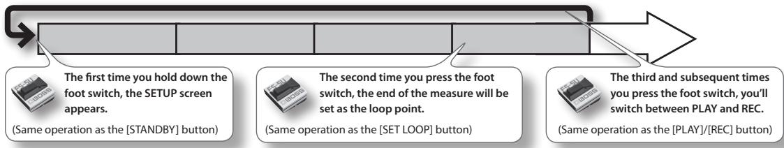
When you take your finger off the [STANDBY] button, it will light and the PHRASE LOOP screen appears.
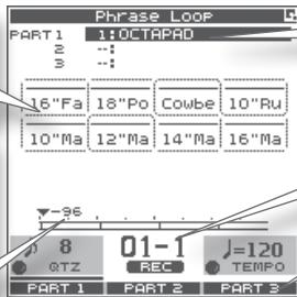
![Turn [Knob 1] (QTZ) to select the quantize interval. Or select "OFF." To start recording, press [Button 2] (START) or hit a pad. Phrase Loop PART 1 1:0 OCTAPAD z : : : s : : : CYM CYM PC1 PC3 16"Fa 18"Po Cowbe 10"Ru TOM TOM TOM TOM 10"Ma 12"Ma 14"Ma 16"Ma HIT PAD TO START The currently selected kit is shown. Turn [Knob 3] (TEMPO) to set the tempo. You can set the tempo manually by tapping [Button 3] (TAP) four times or more. You can also set the tempo by holding down [Button 3] (TAP) and playing a pad four times or more.](/content/2025/01/130963/images/c8fecd7cb472efbb873dc856112a70feb71bbc525e6a1af800af899279b0fd0c.jpg)
Now make settings for the phrase that you will record (quantize to 8th notes, tempo 100).
- Turn [Knob 1] (QTZ) to set quantization to "♪ 8" (8th notes).
If you're confident that you have precise timing, you can leave this setting "OFF."
- Turn [Knob 3] (TEMPO) to set the tempo at "100."
MEMO
You can also set the tempo of the phrase before entering standby mode, in the kit screen.
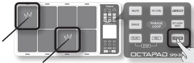
Step 3: Recording
Play the pads in rhythm with the click. Recording automatically begins the moment you hit the first pad.
* Recording or playback will not start even if you press the [REC] button or [PLAY] button. These buttons only switch between Record and Play modes. In order to start the phrase, you must either hit a pad or press [Button 2] (START).
- Hit the pads to record the phrase.
Although you are free to record all pads at the same time, you can also record (overdub) each pad individually, for example by starting with the bass drum, then recording the snare drum, and then the hi-hat etc.
flowchart
graph TD
    A["Start recording!"] --> B["Record the high-hat on the third pass"]
    B --> C["Record the snare drum on the second pass"]
    C --> D["Record the bass drum on the first pass"]
- When you're finished recording, press the [PLAY] button.
The [PLAY] button lights, and you're switched to Play mode. The phrase will play only. No recording is possible.
- If you press the [REC] button again, you return to the Record (REC) mode.
- To stop the phrase, hold down the [PLAY] button and press the [REC] button.
Re-doing the Recording
If you want to re-do the recording, it's easy to use the following methods.
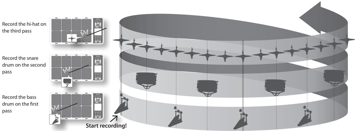
Erasing a Track (ERASE)
During playback or recording, you can erase just the track of a specific pad.
- Hold down the [ERASE] button, and when you want to start erasing, hit the pad whose track you want to erase.
That pad's illumination will blink while its track is being erased.
- Hold down the [ERASE] button, and when you want to stop erasing, hit the pad whose track was being erased.
Undoing a Recording (UNDO)
You can undo the previous recording or erasure. Perform the following step immediately after you've recorded or erased data. You can't undo once you've stopped the phrase.
- In the PHRASE LOOP screen (during PLAY or REC), choose the QUICK MENU command Undo REC (or Undo ERASE).
Clearing the Phrase (CLEAR PHRASE)
If you want to re-record from scratch, you can clear the phrase.
-
In the PHRASE LOOP screen (while stopped), choose the QUICK MENU command Clear Phrase.
-
When the confirmation message appears, press [Button 3] (OK).
Saving the Phrase (SAVE PHRASE)
The recorded phrase will be lost when you exit Phrase Loop mode, select a different phrase, or turn off the power. If you want to keep the phrase, you can save it to internal memory or to USB memory.
- In the PHRASE LOOP screen (while stopped), choose the QUICK MENU command Save Phrase.
When the SAVE PHRASE screen appears, save the phrase as described in the procedure on p. 49.
Exiting Phrase Loop Mode
In the standby condition (while stopped), press the [STANDBY] button to make it go dark; you'll exit Phrase Loop mode and return to the KIT screen.
* If you leave the phrase loop mode without saving your data it will be lost. (A reminder will appear in the screen.)
Advanced techniques
In addition to the Phrase Loop functions explained here, you can mute a specific pad, record knob movements while you use the knobs to control an effect, or reserve the operation that will occur on the next loop.
For details, refer to "Editing a Phrase" (p. 46).
Advance Operation
1 Kit....p. 30
This chapter explains how to create a kit and use effects.
2 Phrase Loop ......p. 43
This chapter provides a full explanation of the Phrase Loop functionality.
3 Other Settings ......p. 52
This chapter explains settings such as pad and pedal calibration, and how to connect MIDI and USB equipment.

Inst Settings (INST)
Inst and Layer Settings (INST-INST)
For more about Insts and Layers, refer to "What is an Inst?" (p. 8). How to access individual Inst parameters for each pad.
1. Choose MENU → INST → INST (p. 16).
The INST-INST screen appears.
![Use [Knob 1] (SEL) to select a parameter. KIT 01 : OCTAPAD Inst INST EDIT HH CTRL Inst Layer Type OFF Layer Point Inst A CYM 13 16"Fast CrBW Inst B SEL ALL... Darkened pad indicator is the pad you're editing. Hit the pad to change this. Turn [Knob 3] (-/+) to edit the value. Press [Button 3] (ALL) to copy the current value to all pads and external triggers.](/content/2025/01/130963/images/53b1b752286eb85986dd8162ec620e14974b26b5570960c02546adcad4700013.jpg)
- Hit the pad that you want to edit; it will be selected.
- Turn [Knob 1] (SEL) to select a parameter.
- Turn [Knob 3] (-/+) to edit the value.
| Parameter | Value | Explanation | ||
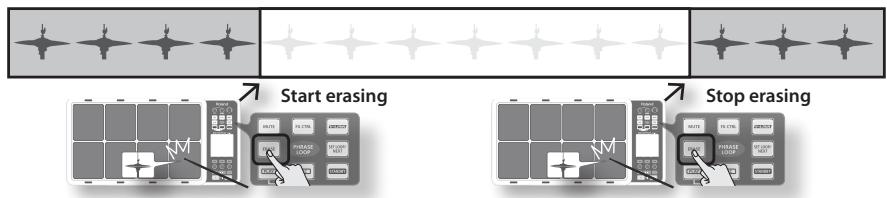
| Inst Layer Type | OFF |  |  | Only Inst A will play.If Layer is set to other than OFF, the indication shown in this illustration will appear at the upper left of the Inst name indication in screens such as the KIT screen. |
| MIX |  | 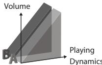 | Inst A and Inst B will both play together.If the Layer Point has been specified, Inst B will be heard only when you hit the pad more strongly than the specified Layer Point velocity value, as shown in the illustration at right. | |
| SWITCH |  | 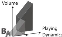 | Hits that are softer than the Layer Point will play Inst A, and hits that are stronger will play Inst B. | |
| FADE |  | 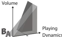 | Inst B will be added to Inst B when you play more strongly than the Layer Point. | |
| XFADE |  | 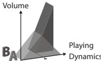 | This is essentially the same as FADE, but Inst A will decrease as you play the pad more strongly than the Layer Point. | |
| Layer Point | 1-127 | Specifies the velocity value at which Inst B will start being heard. | ||
| Inst A | Selects Inst A. For details on how to select this, refer to "02 Selecting an Inst (INST)" (p. 23). | |||
| Inst B | Selects Inst B. For details on how to select this, refer to "02 Selecting an Inst (INST)" (p. 23). | |||
| Mute Group | OFF, 1-6 | On an acoustic drum set, for example, the open hi-hat and closed hi-hat will not be heard simultaneously. You can use Mute Group settings to simulate this behavior.Mute Group is a function that prevents Insts of the same mute group setting from being heard together. You can specify six mute groups. If you don't want an Inst to belong to any mute group, choose "OFF." | ||
| Dynamics | OFF, ON | If you choose OFF, playing dynamics will be ignored, and the Inst will only sound at the maximum velocity (127). | ||
You can't select Inst Layer Type for an external pads
For external pads (p. 60), you can only use 2 sounds: Inst Head and Inst Rim. (Dual trigger pad is needed to have head and rim sounds) Refer to the owner's manual of the pad you're using.
| Internal pads | External pads |
| Inst A | Inst Head |
| Inst B | Inst Rim |

Editing an Inst (INST-EDIT)
Here's how to access the various editing parameters.
1. Choose MENU → INST → EDIT (p. 16).
The INST-EDIT screen appears.
![KIT 01 : OCTAPAD Indicates the pad you're editing; hit a pad to change this. A: OFF B: INST EDIT HH CTRL Tuning Muffling Soft Attack Tone Color Use [Knob 1] (SEL) to select a parameter. [Knob 2] (B) edits the Inst B (Rim) value. [Knob 3] (A) edits the Inst A (Head) value. Press [Button 3] (ALL) to copy the current value to all pads.](/content/2025/01/130963/images/655cda5411ac04253e544f8ef6cd0814f4082481762462bf37d49a60c3c3254e.jpg)
2. Hit the pad that you want to edit; it will be selected.
3. Turn [Knob 1] (SEL) to select a parameter.
4. Turn [Knob 3] (A) or [Knob 2] (B) to edit the value.
• [Knob 2] (B) edits the Inst B (Rim) value.
- [Knob 3] (A) edits the Inst A (Head) value.
| Parameter | Value | Explanation |
| Tuning | -2400–+2400 | Negative (“-”) settings lower the pitch, and positive (“+”) settings raise the pitch. Turning the knob will change the value in steps of 10. |
| Muffling | 0–50 | Increasing this value will decrease the resonance and decay of the sound. |
| Soft Attack | 0–50 | Adjusts the sharpness of the sound’s attack. Higher settings will produce a softer attack. |
| Tone Color | L50–H50 | Adjusts the brightness of the sound. Higher settings will produce a brighter sound. |
| Pitch Sweep | -100–+100 | Positive (“+”) settings make the pitch sweep from high to low. Negative (“-”) settings make the pitch sweep from low to high. |
| Volume | 0–100 | Specifies the volume. |
| Pan | L15–CTR–R15 | Specifies the pan setting. CTR is center. |
| Reverse | OFF, ON | If this is ON, the pad’s sound will play backward.* Some Insts will NOT play in reverse. |
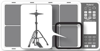
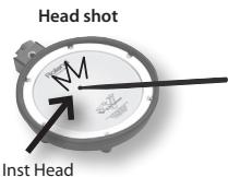
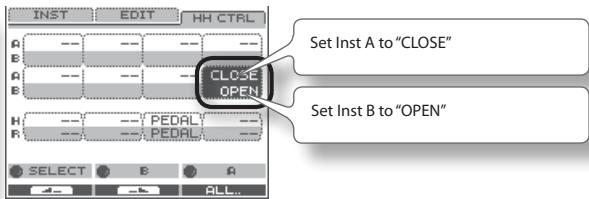
Hi-hat Settings (INST-HH CTRL)
Here you can decide how the hi-hat Inst will sound, and choose the Inst to be controlled by a hi-hat control pedal (FD-8: sold separately).
1. Choose MENU → INST → HH CTRL (p. 16).
The INST-HH CTRL screen appears.
![[Knob 1] (PAD SEL) selects the pad to edit. KIT 01 : OCTAPAD Inst a: OFF B: INST EDIT HH CTRL Values for each pad (Inst A is above, Inst B is below) Values for external trigger inputs 1–4 (Head is above, Rim is below) [Knob 2] (B) edits the Inst B (Rim) value. [Knob 3] (A) edits the Inst A (Head) value.](/content/2025/01/130963/images/c5c670513a42db0b6530dd1f674cbe1645f527c32d56aa9a7b2e9430555bf64f.jpg)
2. Turn [Knob 1] (PADSEL) (or hit a pad) to select the pad that you want to edit.
3. Turn [Knob 3] (A) or [Knob 2] (B) to edit the value.
- [Knob 2] (B) edits the Inst B (Rim) value.
- [Knob 3] (A) edits the Ins A (Head) value.
| Parameter | Value | Explanation |
| HH CTRL | For the hi-hat Inst | |
| CLOSE | Plays the closed hi-hat sound. | |
| HALF | Plays the half-open hi-hat sound. | |
| OPEN | Plays the open hi-hat sound. | |
| PEDAL | Choose “PEDAL” if a hi-hat control pedal (FD-8: sold separately) is connected. The hi-hat sound will switch according to how the hi-hat control pedal is pressed.* Only one of the pads can be set to “PEDAL.” | |
| For other than the hi-hat Inst | ||
| PEDAL | The sound will play when you press the hi-hat control pedal.* Only one of the pads can be set to “PEDAL.” | |
| -- | No sound will play when you press the hi-hat control pedal. | |
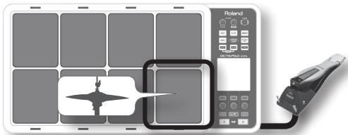
HH CTRL setting examples
If a hi-hat control pedal is connected
Choose "PEDAL" for the pad that's assigned to the hi-hat Inst.
natural_image
Illustration of a solar panel with a bird silhouette and a control panel connected to a handheld device (no text or symbols visible)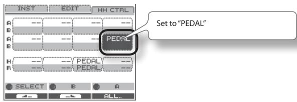
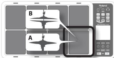
If a hi-hat control pedal is not connected
Make the following settings if you want to assign the closed hi-hat and open hi-hat sounds to two different pads.
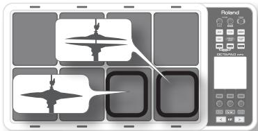
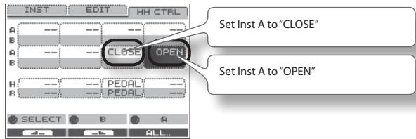
If you want to use one pad to play both the closed hi-hat, and be able to switch to the open hi-hat, choose the same hi-hat Inst for both Inst A and B of a single pad, set "Inst Layer Type" (p. 30) to "SWITCH," and set HH CTRL as follows. Use the "Layer Point" (p. 30) setting to specify the dynamic level at which the hi-hat will open.
INST Screen QUICK MENU
From the INST screen, press the [QUICK] button to access the following QUICK MENU.
| Menu | Explanation | Page |
| Copy Pad | Copy pad settings. | p. 35 |
| Paste Pad | Paste pad settings. | p. 35 |
| Pad Exchange | Access the Pad Exchange screen where you can exchange pads. | p. 36 |
| Multi Edit | Access the MULTI EDIT screen where you can edit the tuning and volume of each pad. | p. 24 |
| Kit Protect ON/OFF | Switch the kit protect setting on/off. | p. 34 |
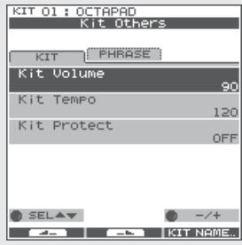
Settings for the Entire Kit (KIT OTHERS)
Kit Volume, Tempo, and Protect (KIT OTHERS-KIT)
Here you can edit the kit's volume, tempo, and protect settings.
1. Choose MENU → OTHERS → KIT (p. 16).
The KIT OTHERS-KIT screen appears.
![[Knob 1] (SEL) selects a parameter. KIT 01 : OCTAPAD Kit Others KIT "PHRASE" Kit Volume 90 Kit Tempo 120 Kit Protect 0FF SEL - /+ KIT NAME... [Knob 3] (-/+) edits the value. Press [Button 3] (KIT NAME) to edit the kit name (p. 35).](/content/2025/01/130963/images/80834707ed4ecf2f324836d072d971cf22d2eff829e2a77ebbbc972caf4849b7.jpg)
2. Turn [Knob 1] (SEL) to select a parameter.
3. Turn [Knob 3] (−/+) to edit the value.
| Parameter | Value | Explanation |
| Kit Volume | 0–100 | The volume of the entire kit. |
| Kit Tempo | OFF, 40–260 | You can specify a tempo for each kit. If the system setting “Kit Tempo Func” (p. 52) is set to ENABLE, the tempo will change to the kit tempo when you switch kits. However, the tempo will not change if the Kit Tempo is Off. |
| Kit Protect | OFF, ON | If Kit Protect is ON, that kit cannot be edited. If Kit Protect is ON, a 📁 icon is shown beside the kit number in the KIT screen. |
Phrase Settings Recalled by the Kit (KIT OTHERS-PHRASE)
You can specify the phrase settings that the kit will recall.
1. Choose MENU → OTHERS → PHRASE (p. 16).
The KIT OTHERS-PHRASE screen appears.
![[Knob 1] (SEL) selects the parameter. KIT 01: OCTAPAD Kit Others KIT : PHRASE Phrase Play 1:Interlude B Tempo CURRENT TEMPO You can assign one Phrase to each kit. Phrase Play is Possible when using the Pad Control function. SEL ▼ -/+ [Knob 3] (-/+) edits the value.](/content/2025/01/130963/images/7584cc126a8b35a1575bfef52d788e5197bdd203442979b804852603dc61fc01.jpg)
2. Turn [Knob 1] (SEL) to select a parameter.
3. Turn [Knob 3] (-/+) to edit the value.
| Parameter | Value | Explanation |
| Phrase Play | OFF, 01–50 | The Phrase Loop will start playing using the phrase you assign here (internal data only) when you hold down the foot switch assigned to the “PAD CTRL” (p. 53) and hit the [Phrase Play] pad. |
| Tempo | PHRASE TEMPO,CURRENT TEMPO | You can choose whether the tempo that will be used following the Phrase Play will be the tempo at the time the phrase was saved (PHRASE TEMPO) or the current tempo (CURRENT TEMPO). |
Assigning a Name (NAME)
Here's how to enter a name for a kit or phrase.
1. From the KIT screen, choose QUICK MENU → Kit Name (p. 15).
* In some cases the NAME palette may also be displayed from other screens as well.
The NAME palette will appear. Use the following knobs and buttons to enter a name; when you're finished, press [Button 3] (OK) to confirm it.
![Cursor Deletes the character at the cursor Inserts a space at the cursor position [KRABID] (ABC) Selects from a list of uppercase characters [KRABID] (abc) Selects from a list of lowercase characters [KRABID] (123) Selects from a list of numerals [Button 1] and [Button 2] move the cursor [Button 3] (OK) Finalizes the name and closes the NAME palette](/content/2025/01/130963/images/7f6faf8946c167fe7f8371912d07608ebec4d5e41d057ac8f3835895a2f97324.jpg)
NAME Palette QUICK MENU
In the NAME palette, pressing the [QUICK] button will access the following QUICK MENU.
| Menu | Explanation |
| Copy Name | Copies the entire text string. |
| Paste Name | Pastes the entire text string. |
| Clear All | Clears the entire text string. |
Copying a Kit or Pad (COPY)
Here's how to copy a kit or pad.
Copying a Pad
This function will copy the most recently-struck pad, and copy its settings to another pad. You can also copy to other kits.
1. From the KIT screen, choose QUICK MENU → Copy → Pad (p. 15).
Alternatively, from the INST screen, choose QUICK MENU → Copy Pad.
With the cursor located at the menu (don't press [Button 3] (OK) yet), the copy-source pad's illumination will blink. If desired, you can change pads by striking a different pad.
2. Press [Button 3] (OK) to copy the pad.
If you want to paste to a different kit, select the paste-destination kit.
3. From the KIT screen, choose QUICK MENU → Paste → Pad.
Alternatively, from the INST screen, choose QUICK MENU → Paste Pad.
With the cursor located at the menu (don't press [Button 3] (OK) yet), the copy-destination pad's illumination will blink. If desired, you can change pads by striking the desired pad.
4. Press [Button 3] (OK) to paste the pad settings.
Copying a Kit
Here's how to copy the currently selected kit.
- Select the copy-source kit.
- From the KIT screen, choose QUICK MENU → Copy → Kit (p. 15).
- Press [Button 3] (OK) to copy the kit.
- Select the copy-destination kit.
- From the KIT screen, choose QUICK MENU → Paste → Kit.
- Press [Button 3] (OK).
A confirmation screen appears. - Press [Button 3] (OK) to paste the kit.
Exchanging Pads (PAD EXCHANGE)
Here's how to exchange the settings of two pads. You can also exchange pads between kits.
- From the KIT screen (or the INST screen, etc.), choose QUICK MENU → Pad Exchange (p. 15).
The PAD EXCHANGE screen appears.
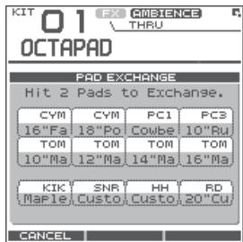
- Hit the first pad to select it.
The selected pad will be shown in the screen, and the selected pad's illumination will blink.
If you want to exchange pads across kits, use the [KIT] buttons to select the desired kit.
If you decide to cancel the procedure, press [Button 1] (CANCEL).
- Hit the pad to be exchanged.
The pad settings will be exchanged.
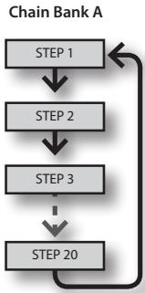
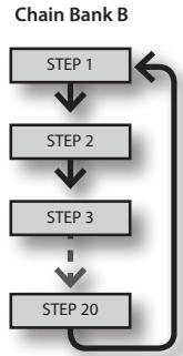
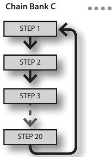
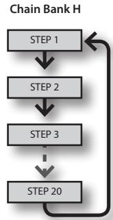
The Kit Chain function lets you decide a specific order in which kits will be switched. This makes it very easy, during live performances, to switch kits in your desired order. You can use the [KIT] buttons or a foot switch (sold separately) to do the switching.
You can create eight Kit Chain Banks (A–H) with 20 kits in each chain.
flowchart
graph TD
    A["STEP 1"] --> B["STEP 2"]
    B --> C["STEP 3"]
    C --> D["STEP 20"]
    D --> A
flowchart
graph TD
    A["STEP 1"] --> B["STEP 2"]
    B --> C["STEP 3"]
    C --> D["STEP 20"]
    D --> A
flowchart
graph TD
    A["STEP 1"] --> B["STEP 2"]
    B --> C["STEP 3"]
    C --> D["STEP 20"]
    D --> A
flowchart
graph TD
    A["STEP 1"] --> B["STEP 2"]
    B --> C["STEP 3"]
    C --> D["STEP 20"]
    D --> A
Creating a Kit Chain (KIT CHAIN)
Here's how to create a kit chain.
1. Choose MENU → Kit Chain (p. 16).
The KIT CHAIN screen appears. Use the following knobs and buttons to create your kit chain.
![[Knob 1] (STEP) changes the step [Button 1] and [Button 2] change banks Kit Chain BANK [A] NAME: Chain 1 STEP: 1 1:OCTAPAD 2 5:Acoustic 3 7:CoolJazz 4 --:(END) STEP -/+ CHAIN Chain bank name (use the QUICK MENU to edit) [Knob 3] (-/+) changes the kit (list display) [Button 3] (CHAIN) turns the chain on/off (When on, a bar is shown above the button.) This can also be switched from the KIT screen QUICK MENU.](/content/2025/01/130963/images/41c22c0b12c768a4588a445cde1150322be78d389cd91692ec0f02e05571fa3f.jpg)
KIT CHAIN Screen QUICK MENU
From the KIT CHAIN screen, press the [QUICK] button to access the following QUICK MENU.
| Menu | Explanation | |
| Move Up | Moves the selected step up one place |  |
| Move Down | Moves the selected step down one place |  |
| Delete | Deletes the selected step, moving up subsequent steps |  |
| Insert | Inserts a step at the selected position |  |
| Chain Name | Assigns a chain bank name (p. 35) | |
| Clear All Steps | Deletes all steps | |
Switching Kit Chains
From the KIT screen, choose QUICK MENU → Kit Chain ON/OFF to turn Kit Chain on/off.
If Kit Chain is on, the CHAIN icon appears in the display. You can use the knobs, [KIT] buttons, or foot switch to move in the order you have decided. You can also switch between the Chain Banks.
![KIT 01 FX AMBENCE CHAIN icon OCTAPAD OFF CYM PC1 PCS OFF 18"Po Cowbe 10"Ru TOM TOM TOM TOM 10"Ma 12"Ma 14"Ma 16"Ma STEP 01 CHAIN:A Chain 1 =120 STEP BANK TEMPO FAVORITE TWEAK FX CTRL The STEP list appears when you turn [Knob 1] (STEP). Press [Button 3] (OK) to confirm. The BANK list appears when you turn [Knob 2] (BANK). Press [Button 3] (OK) to confirm.](/content/2025/01/130963/images/db710b507da53cacd58232d618dd254950f7815df9a7396a49a24a887fab4941.jpg)
The onboard effects processor, "FX", has 30 different effects to choose from.
FX Settings (FX)
Switching the FX Type (FX-TYPE)
Here's how to switch the FX type.
1. Choose MENU → FX → TYPE (p. 16).
The FX-TYPE screen appears.
![KIT 01 : OCTAPAD FX FX THRU TYPE EDIT SEND Effects Type 00:THRU THRU TYPE BYPASS A diagram of the selected FX type is shown. Pads for which FX is enabled FX type [Knob 3] (TYPE) displays a list of FX types. [Button 3] (BYPASS) temporarily turns FX off.](/content/2025/01/130963/images/503330f08d3de59bc8d584ea60c13ebcebdc3bb4646ff4a450564e9f9d7e8d57.jpg)
2. Turn [Knob 3] (- / + ) to select an FX type.
3. Press [Button 3] (OK) to confirm.
| Parameter | Value | Explanation |
| FX Type | 00(THRU)-30 | FX type. If you select "00(THRU)," FX will not be applied. |
Editing FX Parameters (FX-EDIT)
Here's how to edit the parameters of each FX.
1. Choose MENU → FX → EDIT (p. 16).
The FX-EDIT screen appears.
![FX type [Knob 1] (SEL) selects a parameter. KIT 01 : OCTAPAD FX SUPER FILTER TYPE EDIT SEND Type HPF Slope -36[dB] Cutoff 40 Resonance 40 SEL +/- BYPASS Pads for which FX is enabled [Knob 3] (-/+) edits the value. [Button 3] (BYPASS) temporarily turns FX off.](/content/2025/01/130963/images/654903dbacdad9ad50a21486f0daa849227500444e9d021e43294018096bc8c9.jpg)
2. Turn [Knob 1] (SEL) to select a parameter.
3. Turn [Knob 3] (−/+) to edit the value.
- The parameters will differ depending on the FX.
- Parameters for which the following icons are shown can be controlled using the knobs in the FX CONTROL screen (p. 41).
| ●○○ | Knob 1 |
| ○●○ | Knob 2 |
| ○○● | Knob 3 |
Setting the FX Send Level for Each Pad (FX-SEND)
Each pad has its own individual effects send level.
1. Choose MENU → FX → SEND (p. 16).
The FX-SEND screen appears.
![[Knob 1] (PAD SEL) selects the pad to edit. KIT 01 : OCTAPAD FX FX SUPER FILTER TYPE EDIT SEND ON ON ON ON ON ON ON ON H ON ON ON ON ON ON ON ON PAD SEL B BYPASS Value for each pad (Inst A is above, Inst B is below) Value for external trigger inputs 1–4 (Head is above, Rim is below) [Knob 2] (B) edits the Inst B (Rim) value. [Knob 3] (A) edits the Inst A (Head) value.](/content/2025/01/130963/images/59a9009baafe4ed153ceca00d8f91a8a6f5221b085c2d01d4f2b3714ad818f1b.jpg)
2. Turn [Knob 1] (PADSEL) (or hit a pad) to select the pad whose settings you want to edit.
3. Turn [Knob 3] (A) or [Knob 2] (B) to edit the value.
• [Knob 2] (B) edits the Inst B (Rim) value.
- [Knob 3] (A) edits the Inst A (Head) value.
| Parameter | Value | Explanation |
| FX Send | 0–100orOFF, ON | Specifies the FX Send level for each pad.Depending on the FX type, the range will be either “Send level (0–100)” or “OFF, ON.” |
FX Screen QUICK MENU
From the FX screen, press the [QUICK] button to access the following QUICK MENU.
| Menu | Explanation | Page |
| Copy FX | Copies FX settings. | p. 40 |
| Paste FX | Pastes FX settings. | p. 40 |
| Kit Protect ON/OFF | Turns Kit Protect on/off. | p. 34 |
MEMO
The FX-SEND screen parameters can not be copied/pasted. That is why there is no QUICK MENU access in this screen.
Copying FX Settings
The currently selected FX settings can be copied to a different kit.
- From the FX screen, choose QUICK MENU → Copy FX.
- Press [Button 3] (OK) to copy the FX settings.
- Select the copy-destination kit.
- From the FX screen, choose QUICK MENU → Paste FX.
- Press [Button 3] (OK) to paste the FX settings.
Using the Knobs to Control the FX (FX CONTROL)
You can use [Knob 1]–[Knob 3] to control FX parameters. For each FX, the most suitable parameters are automatically assigned to the three knobs.
Changes you make in the FX CONTROL screen are not saved to the kit.
1. Press the [FX CTRL] button.
The FX CONTROL screen appears.
MEMO
You can also access the FX CONTROL screen from the KIT screen by pressing [Button 3] (FX CTRL).
![[Button 1] (SEND) moves to a screen where you can set the send level for each pad. KIT 01 OCTAPAD FX Control FX type Pads for which FX is enabled. [Knob 1–3] adjusts the effect parameters. [Button 3] (BYPASS) temporarily turns FX off. SEND... BYPASS](/content/2025/01/130963/images/b700efca248c6927c5a8a7978e0a65876cba5f96cb2b231aa88aa38b139cd585.jpg)
MEMO
When you're recording a phrase loop (REC mode), knob movements are recorded on the phrase's FX track. [Button 1] operates as TR MUTE; the FX track will be muted when you turn it on.

Adjusting the FX send level for each pad (FX CONTROL-FX SEND)
The FX SEND (FX send level) screen is also accessible from the FX CONTROL screen.
1. Press the [FX CTRL] button.
2. Then press [Button 1] (SEND) to enter the FX SEND (FX send level) screen.
Operations are as mentioned above p. 40.
Remember that any changes made via this page will NOT be saved to the kit. Movements or adjustments to send levels while in Rec mode of the phrase loop will NOT be recorded into the phrase.
This section explains how to adjust the overall sound of the entire OCTAPAD. You can use a choice of Ambiences plus an Equalizer and Limiter. As these effects are applied to the entire OCTAPAD, they will not change when you switch kits.
Ambience Settings (AMBIENCE-AMBIENCE)
Here's how to make Ambience settings. You can make adjustments as appropriate for the environment in which you're playing the drums.
1. Choose MENU → AMBIENCE → AMBIENCE (p. 16).
The AMBIENCE-AMBIENCE screen appears.
![Final output level meter [Knob 1] (SEL) selects a parameter. Ambience FX AMBIENCE AMBIENCE EQ LIMIT Switch ON Type Hall DEPTH 1 OUTPUT CLIP -2 L R SEL +/- + - Ambience on/off Ambience type Ambience depth [Knob 3] (-/+) edits the value.](/content/2025/01/130963/images/9196b31d3f288e6a7874d9a4594060dad36db90c7cdc790d24cc9daa7aefa936.jpg)
2. Turn [Knob 1] (SEL) to select a parameter.
3. Turn [Knob 3] (-/+) to edit the parameter.
| Parameter | Value | Explanation |
| Switch | OFF, ON | Ambience on/offYou can also turn ambience on/off from the KIT screen by choosing QUICK MENU → Ambience ON/OFF. |
| Type | 1–7 | Ambience type |
| Depth | 1–10 | Ambience depth |
Equalizer Settings (AMBIENCE-EQ)
Here's how to make Equalizer settings that adjust the tonal character of the low, middle and high frequency ranges.
1. Choose MENU → AMBIENCE → EQ (p. 16).
The AMBIENCE-EQ screen appears. The editing procedure is the same as for Ambience.
| Parameter | Value | Explanation |
| Switch | OFF, ON | Equalizer on/off |
| High | -12–+6 dB | High range boost/cut |
| Mid | -12–+6 dB | Middle range boost/cut |
| Low | -12–+6 dB | Low range boost/cut |
Limiter Settings (AMBIENCE-LIMIT)
Here's how to make Limiter settings that compress sounds that are louder than a specified volume level, thus making the volume more consistent.
1. Choose MENU → AMBIENCE → LIMIT (p. 16).
The AMBIENCE-LIMIT screen appears. The editing procedure is the same as for Ambience.
| Parameter | Value | Explanation |
| Switch | OFF, ON | Limiter on/off |
| Threshold | -12–0 dB | Volume level at which compression will begin |
For an overview of Phrase Loop, refer to "What is a Phrase Loop?" (p. 9).
Measures, Time Signature (Beat) and Metronome (Click) Sound Settings (SETUP)
Hold down the [STANDBY] button; the PHRASE LOOP SETUP screen appears.
![Press [Button 2] (CLICK); a bar appears above the button, and the click (Metronome) will start. Phrase Loop SETUP Measures 2 4 8 16 2 3 4 6 Beat The position you hit on the pads will be selected. The upper row is Measures, the lower row is Beat. You can also edit the values by turning [Knob 1] (MEAS) or [Knob 2] (BEAT).](/content/2025/01/130963/images/0017e0b13b94693b3a86d18b763898f2cbcd2cdbadbdc32fc7ef3e5bdbb35cad.jpg)
For details on operation, refer to "Measures, Time Signature (Beat) and Metronome (Click) Sound settings" (p. 26).
| Parameter | Value | Explanation |
| Measures | 1–96, FREE | Number of measures in the phrase.If you choose “FREE,” use the [SET LOOP] button during recording to set the loop point (see below).You can use “Default Measures” (p. 51) to specify the default value of this parameter. |
| Beat | 1–9 | Time signature of the phrase.You can use “Default Beat” (p. 51) to specify the default value of this parameter. |
| Click | OFF, ON | Metronome (click) sound on/off.You can use “Default Click” (p. 51) to specify the default value of this parameter.As described in “Metronome (Click) Sound Settings (PHRASE LOOP SETUP-CLICK)” (p. 51), you can make the click sound only on the first pass of the loop, change the type of click sound, and adjust the click volume. |
Using the [SET LOOP] Button to Set the Loop Point
If the STANDBY screen's Measures parameter is set to "FREE," you can use the [SET LOOP] button to set the loop point during recording.
If Measures is set to "FREE," the [SET LOOP] button will blink during recording (or during playback). When you've entered the measure at which you want to loop, press the [SET LOOP] button; the end of that measure will be set as the loop point.
* You can't set the loop point in the middle of a measure.
![ROLAND OCTAPAD SPD-30 - Using the [SET LOOP] Button to Set the Loop Point - 1](/content/2025/01/130963/images/3405a95bec241e2f9a114ef7a4904b23c389f33f8559ab0d64c306e839767c51.jpg)
flowchart
graph LR
    A["Start"] --> B["Press the [SET LOOP"] button]
    B --> C["SET LOOP NOT Gate"]
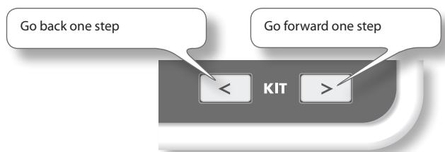
Using a foot switch to set the loop point
If you connect a foot switch (FS-5U, sold separately; p. 53) and set the system setting "Foot Sw" (p. 53) to "PHRASE-LOOP CTRL," you'll be able to set the loop point by pressing the foot switch.
flowchart
graph LR
    A["The first time you hold down the foot switch, the SETUP screen appears. (Same operation as the [STANDBY"] button)] --> B["The second time you press the foot switch, the end of the measure will be set as the loop point. (Same operation as the [SET LOOP"] button)]
    B --> C["The third and subsequent times you press the foot switch, you'll switch between PLAY and REC. (Same operation as the [PLAY"]/[REC] button)]
Quantize and Tempo Settings (STANDBY)
Press the [STANDBY] button; the [STANDBY] button will light, and the PHRASE LOOP STANDBY screen appears.
Turn [Knob 1] (QTZ) to set the quantization. If you select "OFF," quantization will not be applied.
Press [Button 2] (START) or hit a pad to start recording.
The currently selected kit is shown here.
Turn [Knob 3] (TEMPO) to set the tempo.
You can set the tempo by pressing [Button 3] (TAP) four times or more at the desired tempo (Tap Tempo). In the same way, you can also set the tempo by holding down [Button 3] (TAP) and striking a pad four times or more at the desired tempo.
For details on operation, refer to "Quantization and tempo settings" (p. 27).
| Parameter | Value | Explanation |
| QTZ (Quantize) | OFF, 8 , 3 12, 16 , 3 24 | The Quantize function automatically corrects inaccuracies in the timing at which you play the pads during recording. If you've enabled Quantize, your hits will be recorded at precise intervals of 8th notes, 12th note triplets, 16th notes, or 24th note triplets. Quantize works only during recording. |
| Tempo | 40–260 | This is the tempo of the phrase. If the OCTAPAD's tempo is synchronized to an external clock (see “MIDI Sync” (p. 65)), you can also synchronize beyond the specified tempo. Instead of the tempo value, the tempo field will indicate the external clock source (“MIDI” or “USB”). |
STANDBY Screen QUICK MENU
From the PHRASE LOOP STANDBY screen, press the [QUICK] button to access the following QUICK MENU.
| Menu | Explanation | Page |
| Part 1 | ||
| Part 2 | Changes the current part (the currently selected part). | p. 44 |
| Part 3 | ||
| Click ON/OFF | Turns the click sound on/off. | p. 43 |
| Phrase List | Opens the PHRASE LIST screen, allowing you to load a phrase. | p. 50 |
| Save Phrase | Saves the phrase. | p. 49 |
| Clear Phrase | Erases the currently selected phrase. | p. 28 |
Switching the Part's Kit (STANDBY)
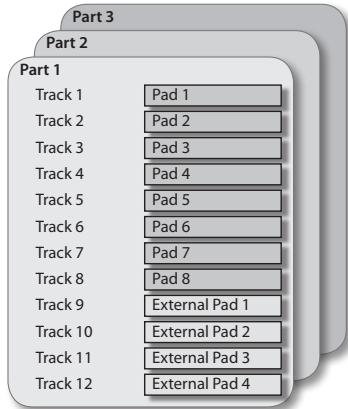
Each phrase has three parts, and each part can simultaneously play a different kit.
1. From the PHRASE LOOP STANDBY screen, open the QUICK MENU and choose Part 1–3.
The current part (currently selected part) will change.

2. Use the [KIT] buttons to switch kits.
The kit of the current part will change.
NOTE
If not even one note has been recorded in the part (such as when you've loaded a phrase), a check mark is shown for the part, and you won't be able to switch kits.
Recording a Phrase (REC Mode)
From the PHRASE LOOP STANDBY screen, press [Button 2] (START) or hit a pad to start recording.
Shows each pad's track data and Inst name.
The bar indicates the data of all parts, and the position pointer ▼ and remaining measures are shown.
This indicates each part's kit. If not even one note has been recorded in a part, a check mark is displayed and you won't be able to switch kits.
Indicates the current measure and beat.
You can use [Button 1] (PART 1)–[Button 3] (PART 3) to switch the current part.
For details on operation, refer to "Step 3: Recording" (p. 27).
MEMO
You can cancel (Undo) the recording you just performed (p. 28).
Performing Along with a Recorded Phrase (PLAY Mode)
Press the [PLAY] button; the [PLAY] button will light, and you'll switch to Play mode. Recording will not occur even if you play the pads.
Shows each pad's track data and Inst name.
The bar indicates the data of all parts, and the position pointer ▼ and remaining measures are shown.

This indicates each part's kit. If not even one note has been recorded in a part, a check mark is displayed and you won't be able to switch kits.
Indicates the current measure and beat.
You can use [Button 1] (PART 1)–[Button 3] (PART 3) to switch the current part.
REC/PLAY Screen QUICK MENU
From the PHRASE LOOP STANDBY screen, press the [QUICK] button to access the following QUICK MENU.
| Menu | Explanation | Page |
| Undo REC (or Undo ERASE) | You can undo a recording or erase operation that you just performed. Immediately after recording or erasing, perform the following operation. Once you stop the phrase, it will no longer be possible to Undo. | p. 28 |
| Part Level | Adjusts the level of parts 1–3. | p. 48 |
| Favorite ON | When ON, you can choose kits from favorite kits only. | p. 22 |
| Kit Chain ON | When ON, you can choose kits from the Kit Chain only. | p. 37 |
| Fav/Chain OFF | This turns either of the 2 above choices OFF. | — |
| Click ON/OFF | Turns the click sound on/off. | p. 43 |
| Clear Part Data | Erases the data of the currently selected part. A confirmation screen will appear; press [Button 3] (OK) to confirm. | — |
Stopping the Phrase (STOP)
To stop the phrase, hold down the [PLAY] button and press the [REC] button.
You will return to the STANDBY screen (p. 44).
What You can do in REC/PLAY Mode
In Phrase Loop record or play mode, you can press the following buttons to access various realtime editing or performance functions. This ability to modify phrases in realtime is one of the OCTAPAD's most important and distinguishing features.
| Button | Explanation | Page |
 | Switches to Play (PLAY) mode. Recording will not occur even if you play the pads. | p. 45 |
 | Switches to Record (REC) mode. Your pad performance will be recorded. | p. 45 |
 | By holding down the [MUTE] button and striking a pad, you can mute or un-mute that track.The mute status is shown in the display and by the pad status illumination. | p. 46 |
 | By holding down the [ERASE] button and striking a pad, you can selectively erase an unwanted section of a track. Hit the pad at the beginning of the section you want to erase, and hit it once again at the end of the section. The erase status is shown in the display and by the pad status illumination. | p. 47 |
 | Press the [FX-CTRL] button to access the FX-CONTROL screen, where you can use the knobs to control the effect. If you're recording a phrase loop, the knob movements can be recorded. | p. 41 |
 | When button is blinking: Sets the loop point. | p. 43 |
| When button is lit: Reserves the operation (MUTE/PLAY/REC/STOP) that will occur at the beginning of the next loop. | p. 47 |
MEMO
If you've connected a foot switch and set the system setting "Foot Sw" to "PAD CTRL," you can hold down the foot switch and hit a pad to perform the same operations as the buttons listed above. See Foot switch (p. 53).
Muting a Track (MUTE)
Hold down the [MUTE] button; the PHRASE LOOP MUTE screen appears.
![Muted pads (tracks) are shaded gray. Pressing [Button 2] (FLIP ALL) will exchange the muted and un-muted status of all tracks. 01-1 MUTE Flip ALL MUTE ALL Phrase Loop PART 1 1: OCTAPAD 2 : : : 3 : : : 5:43 18"Po Cowbe 10"Ru 10"Ma 12"Ma 14"Ma 16"Ma Pad Status Illumination Muted Data exists No data Blinking Lit Dark Pressing [Button 3] (MUTE ALL) will temporarily mute all tracks.](/content/2025/01/130963/images/4b575b033c334328a8ba39387dbd51adfe9db86180a6d3cbbd58981421c8f18f.jpg)
By holding down the [MUTE] button and striking a pad, you can mute or un-mute that track.
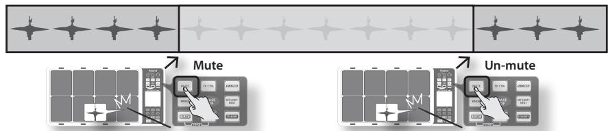
flowchart
graph TD
    A["State 1"] --> B["Mute"]
    C["State 2"] --> D["Mute"]
    E["State 3"] --> F["Mute"]
    G["State 4"] --> H["Mute"]
    I["State 5"] --> J["Mute"]
    K["State 6"] --> L["Mute"]
    M["State 7"] --> N["Mute"]
    O["State 8"] --> P["Mute"]
    Q["State 9"] --> R["Mute"]
    S["State 10"] --> T["Mute"]
    U["State 11"] --> V["Mute"]
    W["State 12"] --> X["Mute"]
    Y["State 13"] --> Z["Mute"]
    AA["State 14"] --> AB["Mute"]
    AC["State 15"] --> AD["Mute"]
    AE["State 16"] --> AF["Mute"]
    AG["State 17"] --> AH["Mute"]
    AI["State 18"] --> AJ["Mute"]
    AK["State 19"] --> AL["Mute"]
    AM["State 20"] --> AN["Mute"]
    AO["State 21"] --> AP["Mute"]
    AQ["State 22"] --> AR["Mute"]
    AS["State 23"] --> AT["Mute"]
    AU["State 24"] --> AV["Mute"]
    AW["State 25"] --> AX["Mute"]
    AY["State 1"] --> AZ["Mute"]
    BA["State 2"] --> BB["Mute"]
    BC["State 3"] --> BD["Mute"]
    BE["State 4"] --> BF["Mute"]
    BG["State 5"] --> BH["Mute"]
    BI["State 6"] --> BJ["Mute"]
    BK["State 7"] --> BL["Mute"]
    BM["State 8"] --> BN["Mute"]
    BO["State 9"] --> BP["Mute"]
    BQ["State 10"] --> BR["Mute"]
    BS["State 11"] --> BT["Mute"]
    BU["State 12"] --> BV["Mute"]
    BW["State 13"] --> BX["Mute"]
    BY["State 14"] --> BZ["Mute"]
    CA["State 15"] --> CB["Mute"]
    CC["State 16"] --> CD["Mute"]
    CE["State 17"] --> CF["Mute"]
    GD["State 18"] --> DH["Mute"]
    DI["State 19"] --> DJ["Mute"]
    DK["State 20"] --> DL["Mute"]
    DV["State 21"] --> DV
    DW["State 22"] --> DW
    BXM["State 23"] --> BXM
    BYM["State 24"] --> BYM
    BZM["State 25"] --> BZM
    BZM --> BZM
    BZM --> BZM
    BZM --> BZM
    BZM --> BZM
    BZM --> BZM
    BZM --> BZM
    BZM --> BZM
    BZM --> BZM
    BZM --> BZM
    BZM --> BZM
    BZM --> BZM
    BZM <-->|Un-mute| BZM
    style A fill:#f9f,stroke:#333
    style B fill:#ccf,stroke:#333
    style C fill:#cfc,stroke:#333
    style D fill:#fcc,stroke:#333
    style E fill:#cff,stroke:#333
    style F fill:#ffc,stroke:#333
    style G fill:#fcc,stroke:#333
    style H fill:#fcc,stroke:#333
    style I fill:#fcc,stroke:#333
    style J fill:#fcc,stroke:#333
    style K fill:#fcc,stroke:#333
    style L fill:#fcc,stroke:#333
    style M fill:#fcc,stroke:#333
    style N fill:#fcc,stroke:#333
    style O fill:#fcc,stroke:#333
    style P fill:#fcc,stroke:#333
    style Q fill:#fcc,stroke:#333
    style R fill:#fcc,stroke:#333
    style S fill:#fcc,stroke:#333
    style T fill:#fcc,stroke:#333
    style U fill:#fcc,stroke:#333
    style V fill:#fcc,stroke:#333
    style W fill:#fcc,stroke:#333
    style X fill:#fcc,stroke:#333
    style Y fill:#fcc,stroke:#333
    style Z fill:#fcc,stroke:#333
    style AA fill:#fcc,stroke:#333
    style AB fill:#fcc,stroke:#333
    style AC fill:#fcc,stroke:#333
    style AD fill:#fcc,stroke:#333
    style AE fill:#fcc,stroke:#333
    style AF fill:#fcc,stroke:#333
    style AG fill:#fcc,stroke:#333
    style AH fill:#fcc,stroke:#333
    style AI fill:#fcc,stroke:#333
Differences in muting between Play mode and Rec mode
In Play mode, muted tracks will not be heard. For example, you could mute the snare drum and bass drum tracks, and hit the pads to play these yourself.
In Rec mode, muted tracks will not be heard, just as in Play mode. The difference is that in Rec mode, striking the pad of a muted track will erase all data from that track and un-mute that track.
Erasing a Track (ERASE)
Hold down the [ERASE] button; the PHRASE LOOP ERASE screen appears.
![The text label of the pad (track) being erased will blink. Pressing [Button 1] (CANCEL) will cancel all of the erase start points, and recover the data. 01-1 ERASE CANCEL FX TRACK Pad Status Illumination Erasing Data exists No data Blinking Lit Dark Pressing the [Button 3] (FX TRACK) will delete the entire FX Control track (p. 41).](/content/2025/01/130963/images/b4cfab8835c047844559de30e02c7ec7668fc15acf967436dac45e87c657ada7.jpg)
By holding down the [ERASE] button and striking a pad, you can selectively erase an unwanted portion of a track. Hit the pad at the beginning of the section you want to erase, and hit it once again at the end of the section.
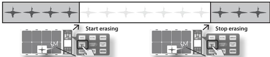
MEMO
- You can undo the erase operation that you just performed (p. 28).
- When in the record mode, if you play a pad that you are actually erasing, that sound will be recorded.
Reserving the Operation at the Next Loop (NEXT)
Here's how to reserve the operation (MUTE/PLAY/REC/STOP) that will occur at the beginning of the next loop.
Perform this operation in Rec or Play modes (while a phrase is playing).
1. Press the [SET LOOP/NEXT] button.
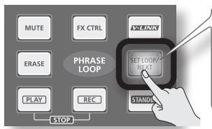
* If the [SET LOOP/NEXT] button is blinking slowly (i.e., when the loop point has not been set), it will operate as the SET LOOP function (p. 43), so you won't be able to reserve the next operation. If the [SET LOOP/NEXT] button is lit, you will be able to reserve the next operation.
2. Press the button that you want to reserve.
You can reserve MUTE, PLAY, REC, or STOP.
![If you're reserving the Mute operation, hold down the [MUTE] button and hit the pad that you want to mute. The [SET LOOP/NEXT] button will blink. If you're reserving the Stop operation, press the [PLAY] button and [REC] button simultaneously.](/content/2025/01/130963/images/ad7afd83b5c18a6f59a95dc204392e8f4b19ab13db9bb010deb9a1fe9c868dc2.jpg)
The button whose operation you reserved will blink. The next time the phrase reaches the beginning of the loop, the reserved operation will occur.
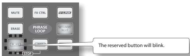
Adjusting the Volume of Each Part (PART LEVEL)
Here's how to adjust the level of parts 1–3.
1. From the PHRASE LOOP screen (during Rec or Play), choose the QUICK MENU command Part Level.
Use the three knobs to adjust the level of parts 1–3. Press the [BACK] button to return to the REC/PLAY screen.
![Use [Knob 1]–[Knob 3] to adjust the level of parts 1–3. Phrase Loop PART 1 1: OCTAPAD 80 80 80 PART1 Level PART2 Level PART3 Level -96 01-1 PART LEVEL PART 1 PART 2 PART 3 Indicates the current part and each part's kit. You can use [Button 1] (PART 1)–[Button 3] (PART 3) to switch the current part.](/content/2025/01/130963/images/26f46945f5f583ab5fdb6d7fd3be34ef1e2079d55e4c34f7dde876d13cf2a664.jpg)
Exiting Phrase Loop Mode
From the standby condition (i.e., stopped), press the [STANDBY] button to make it go dark; you will exit Phrase Loop mode and return to the KIT screen.
* If you leave the phrase loop mode without saving your data it will be lost. (A reminder will appear in the screen.)
Saving a Phrase (SAVE PHRASE)
A phrase you record will be lost when you select a different phrase or turn off the power. You can save the phrase to internal memory or to USB memory.
1. From the PHRASE LOOP screen (while stopped), choose the QUICK MENU command Save Phrase.
The SAVE PHRASE screen appears. Use the following knob and buttons to select the save-destination, and then press [Button 3] (SAVE) to save the phrase.
If you select a number that already contains data, a screen will ask you to confirm the overwrite. Press [Button 3] (OK) to save the phrase.
![Turn [Knob 1] (SAVE TO) to select the save-destination phrase number. Press [Button 1] to switch between internal (INT) and USB memory. Save Phrase INT USE 01 Interlude 02 Interlude 03 Interlude 04 Interlude 05 Interlude 06 Interlude 07 Interlude 08 Interlude SAVE TO Name To USB NAME SAVE Press [Button 2] (NAME) to access the NAME palette (p. 35), where you can assign a name to the phrase. Press [Button 3] (SAVE) to execute the Save operation.](/content/2025/01/130963/images/fbd16758260ba595dd816625bed5c4521536d88eb6a1f68e99b692b1a51c115f.jpg)
Loading a Phrase (PHRASE LIST)
Phrases saved to internal memory or USB memory can be selected from a list and previewed, or you can load that phrase and use Phrase Loop to play it or record additional material into it.
1. Choose MENU → LIST (p. 16).
The PHRASE LIST screen appears. Use the following knob and buttons to select a phrase, and then press [Button 3] (STANDBY); the phrase will be loaded and the STANDBY screen (p. 44) will appear.
![Turn [Knob 1] (SELECT) to select the phrase number that you want to load. Press [Button 1] to switch between internal (INT) and USB memory. Phrase List INT USE o1 Interlude o2 Interlude o3 Interlude o4 Interlude o5 Interlude o6 Interlude o7 Interlude o8 Interlude SELECT PART1 1: OCTAPAD z :: 3 :: J=120 MEAS:4 BEAT:4 TO USB PREVIEW STANDBY... Information about the selected phrase is shown here. Press [Button 2] (PREVIEW) to audition the phrase. Press [Button 3] (STANDBY) to load the phrase and go to the STANDBY screen (p. 44).](/content/2025/01/130963/images/8f835cc8f4f5c25b37767298881bc86c6b020e89fba6197f1c5f58bc18954743.jpg)
* Do not hit the pads while you're auditioning (PREVIEW) a phrase from USB memory. The vibration may cause errors.
PHRASE LIST Screen QUICK MENU
From the PHRASE LIST screen, press the [QUICK] button to access the following QUICK MENU.
| Menu | Explanation | Page |
| Change Name | Displays the NAME palette, where you can assign a name to the phrase. | p. 35 |
| Delete Phrase | Deletes the phrase selected in the list. A confirmation message will appear; press [Button 3] (OK) to confirm the deletion. | — |
Phrase Loop Settings (PHRASE LOOP SETUP)
Here's how to make phrase loop settings.
1. Choose MENU → SETUP → SETUP (p. 16).
The PHRASE LOOP SETUP-SETUP screen appears.
![[Knob 1] (SEL) selects a parameter. PhraseLoop Setup SETUP CLICK Default Measures FREE Default Beat 4 Default Click OFF Part 1 MIDI Ch 11 Part 2 MIDI Ch 12 SELAY -/+ - [Knob 3] (-/+) edits the value.](/content/2025/01/130963/images/4be7a250c0a9d90b065c8801ff5b6883aae985b27b3ee876f38d942688065ae5.jpg)
2. Turn [Knob 1] (SEL) to select a parameter.
3. Turn [Knob 3] (-/+) to edit the value.
| Parameter | Value | Explanation | |
| Default Measures | 1–96, FREE | The default Measures value shown in the SETUP screen | MEMOIf you've specified the desired values here, you can simply press the [STANDBY] button and these values will be shown in the phrase loop standby screen. |
| Default Beat | 1–9 | The default Beat value shown in the SETUP screen. | |
| Default Click | OFF, ON | The default Click value shown in the SETUP screen. | |
| Part1 MIDI Ch | The MIDI channel of each part. | ||
| Part2 MIDI Ch | 1–16, OFF | MEMO | |
| Part3 MIDI Ch | MIDI channels for each pad outside of Phrase Loop mode are specified by “CH” (p. 63). | ||
| Tx Start/Stop | OFF, ON | If this is ON, the MIDI messages FA/FC will be transmitted when you start/stop the phrase loop. | |
| Rx Start/Stop | OFF, ON | If this is ON, the MIDI messages FA/FC (start/stop) will be received in the Phrase Loop mode. | |
Metronome (Click) Sound Settings (PHRASE LOOP SETUP-CLICK)
Here's how to choose the sound used by the metronome (click).
1. Choose MENU → SETUP → CLICK (p. 16).
The PHRASE LOOP SETUP-CLICK screen appears.
![[Knob 1] (SEL) selects a parameter. PhraseLoop Setup SETUP CLICK Sound Click Volume 7 Pan CTR 1st Loop Only OFF [Knob 3] (-/+) edits the value. Press [Button 3] (PREVIEW) to audition the click sound.](/content/2025/01/130963/images/4389c739cecad321d212e8a5005559078dd3581b3ec23d4175d3003d8f7ae92c.jpg)
2. Turn [Knob 1] (SEL) to select a parameter.
3. Turn [Knob 3] (-/+) to edit the value.
| Parameter | Value | Explanation |
| Sound | (Inst Name) | Type of click sound. |
| Volume | 0–10 | Volume of click sound. |
| Pan | L15–CTR–R15 | Pan setting of click sound. CTR is center. |
| 1st Loop Only | OFF, ON | If this is ON, the click sound will be heard only on the first cycle of the phrase loop; it will not be heard on the second and subsequent cycles.* If nothing was recorded on the first cycle, the click will be heard on the second cycle as well. |
Settings for the Entire OCTAPAD (SYSTEM)
These settings apply to the entire OCTAPAD.
1. Choose MENU → SYSTEM (p. 16).
The SYSTEM screen appears.
Use [Button 1] and [Button 2] to switch tabs.
For details on each screen, refer to the pages listed below.
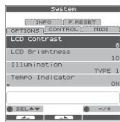
| Screen | Explanation | Page |
| OPTIONS | Make screen and illumination settings. | p. 52 |
| CONTROL | Make foot switch and external pad settings. | p. 53 |
| MIDI | Make MIDI settings for the entire OCTAPAD. | p. 65 |
| INFO | View information about the system. | p. 54 |
| F.RESET | Reset the OCTAPAD to its factory-set state. You can also restore an individual kit to its factory-set state. | p. 20 |
Screen and Illumination Settings (SYSTEM-OPTIONS)
1. Choose MENU → SYSTEM → OPTIONS (p. 16).
The SYSTEM-OPTIONS screen appears.
[Knob 1] (SEL) selects a parameter.
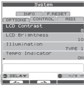
[Knob 3] (- / + ) edits the value.
| Parameter | Value | Explanation |
| LCD Contrast | 1–10 | Adjusts the contrast of the display. |
| LCD Brightness | 1–10 | Adjusts the brightness of the display. |
| Illumination | OFF | Specifies how the [KIT] buttons and pad status illumination will be lit. When you edit this setting, the actual buttons and illumination will change accordingly, allowing you to see the result. With the “OFF” setting, the buttons and pad status illumination will remain unlit at all times. |
| TYPE 1 | Only the [KIT] buttons will be lit. | |
| TYPE 2 | The [KIT] buttons will be lit. The pad status illumination will light only when a pad is struck. | |
| TYPE 3 | The [KIT] buttons and pad status illumination will be lit at all times. This is a good setting to use if you need to know the location of the pads when performing on a dark stage. | |
| Tempo Indicator | OFF, ON | Specifies the lit state of the tempo indicator (PHRASE LOOP). With the “OFF” setting, it will not light, and the KIT screen's tempo indication will also be off. |
| Ext Pad Indicator | OFF, ON | Turns the KIT screen's external trigger indicator on/off.If this is on, the indication will be as shown in the illustration at right.If this is off, a simpler indication will be shown, and the pad's Inst name will be displayed only when a pad is struck. |
| Kit Tempo Func | DISABLE, ENABLE | Specifies whether each kit's “Kit Tempo” (p. 34) will be enabled. If you choose ENABLE, the tempo will change to the kit tempo when you switch kits. However, it will not change if the kit tempo is set to OFF. |
| V-LINK Button Lock | OFF, ON | When the lock is on, the [V-LINK] button does not function. |
| Write Protect | OFF, ON | If the write protect setting is on, it will not be possible to save any settings. |
Foot Switch and External Pad Settings (SYSTEM-CONTROL)
Connecting Foot Switches
You can connect foot switches to the FOOT SW jack.
You can use a dedicated cable (PCS-31L: sold separately) to connect two foot switches (FS-5U: sold separately).
The foot switch connected to the black plug is foot switch 1, and the one with the red plug is foot switch 2.
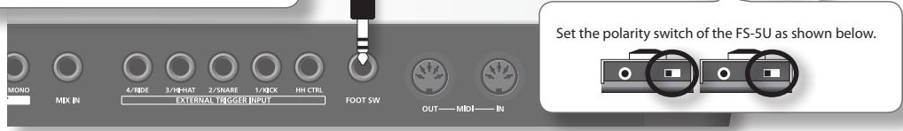
MEMO
Alternatively, you can connect a single pedal switch (DP-2: sold separately) instead of the FS-5U. In this case, the DP-2 will operate as foot switch 1.

Making Settings
1. Choose MENU → SYSTEM → CONTROL (p. 16).
The SYSTEM-CONTROL screen appears.
| Parameter | Value | Explanation |
| OFF | Specify the operation of foot switches 1 and 2. With the "OFF" setting, the foot switches will not work. | |
| PAD CTRL | A popup menu will appear when you hold down the foot switch. Hold down the foot switch and hit a pad to operate the function that's assigned to that pad. Sound will not be produced. | |
| KIT mode | ||
| Tap Tempo Set the tempo by striking the same pad four times or more successively at the desired interval (Tap Tempo). | ||
| FX Bypass Same operation as the [BYPASS] button of the FX Control screen (p. 41). | ||
| Phrase Play Recall the phrase assigned in "KIT OTHERS-PHRASE" (p. 34), and start the phrase loop in Play mode.You can't select this if no phrase has been assigned. | ||
| P.LoopStdby Jump to the Phrase Loop Standby screen (p. 44).The setup screen (p. 43) will be enabled while you hold down the pedal. | ||
| Kit < Select the previous kit (or the previous step if Kit Chain is on). | ||
| Kit > Select the next kit (or the next step if Kit Chain is on). | ||
| Phrase Loop mode | ||
| ERASE Same operation as the [ERASE] button (p. 47). | ||
| MUTE Same operation as the [MUTE] button (p. 46). | ||
| FX Bypass Same operation as the [BYPASS] button of the FX Control screen (p. 41). | ||
| SET/NEXT Same operation as the [SET LOOP/NEXT] button (p. 43, p. 47). | ||
| PLAY Same operation as the [PLAY] button (p. 45). | ||
| REC Same operation as the [REC] button (p. 45).MEMOYou can stop the phrase by hitting the [PLAY]/[REC] pads simultaneously. | ||
| Part < Select the previous part. | ||
| Part > Select the next part. |
| PHRASE-LOOP CTRL | Execute the phrase loop operations STANDBY → SET LOOP → PLAY ← → REC (p. 43). |
| KIT + | Select the next kit (or the next step if Kit Chain is on). |
| KIT - | Select the previous kit (or the previous step if Kit Chain is on). |
| Parameter | Value | Explanation |
| Ext Pad 1 | OFF | Specify the operations that will occur when you hit Ext Pad 1–4. With a setting other than “OFF,” the assigned pad will no longer produce sound. |
| PHRASE-LOOP CTRL | Execute the phrase loop operations STANDBY → SET LOOP → PLAY ← → REC. | |
| Ext Pad 2 | KIT + | Select the next kit (or the next step if Kit Chain is on). |
| Ext Pad 3 | KIT – | Select the previous kit (or the previous step if Kit Chain is on). |
| Ext Pad 4 | PHRASE PLAY | Recall the phrase assigned in “KIT OTHERS-PHRASE” (p. 34), and start the phrase loop in Play mode. |
| TAP TEMPO | Set the tempo by striking the same pad four times or more successively at the desired interval (Tap Tempo). | |
| FootSw1 Polarity | NORMAL, INVERT | This specifies the polarity of the foot switch. If the foot switch does not operate as you expect, try changing this setting. |
| FootSw2 Polarity |
Viewing Information About the System (SYSTEM-INFO)
1. Choose MENU → SYSTEM → INFO (p. 16).
The SYSTEM-INFO screen appears.
| Parameter | Explanation |
| Internal Memory | Remaining amount of internal memory. |
| Program Version | System program version. |
| Sound Version | Sound version. |
| Serial# | Serial number. |
By connecting a USB memory (sold separately), you can back up all of the OCTAPAD's settings (or even just an individual kit) to USB memory.
Don't hit the pads when you're in the USB screen!
If you hit the pads while USB memory is being read or written, the vibration may cause errors to occur. For this reason, the pads are disabled and will not produce sound while you're in the USB screen.
Use USB memory sold by Roland!
We cannot guarantee operation if other products are used.
Don't disconnect USB memory while the OCTAPAD is powered-on!
Doing so may damage the USB memory or the data.
Carefully insert the USB memory all the way in—until it is firmly in place!
Don't connect any device other than USB memory to the USB MEMORY connector!
Formatting USB Memory (USB-FORMAT)
Format (initialize) the USB memory (sold separately) before using it with the OCTAPAD for the first time.
NOTE
When you format USB memory, all data in the USB memory will be erased. Copy any important data to your computer before you proceed.
- Connect your USB memory to the USB MEMORY connector.
- Choose MENU → USB → FORMAT (p. 16).
The USB-FORMAT screen appears.
![USB SAVE LOAD VIEW FORMAT FORMAT USB MEMORY FORMAT ENTER Press [Button 3], a confirmation screen appears.](/content/2025/01/130963/images/e065cb6754ab5b3422d88871d77f6872bc30b5aa74e73e766986a4971e5f41d0.jpg)
- Press [Button 3] (ENTER).
A confirmation screen appears.
- Press [Button 3] (FORMAT).
A confirmation screen will appear again.
- Press [Button 3] (OK).
Formatting will begin. A completion screen will appear when formatting is completed.
Saving Data to USB Memory (USB-SAVE)
Here's how to back up all of the OCTAPAD's settings, or the settings of one specific kit, to USB memory.
1. Choose MENU → USB → SAVE (p. 16).
The USB-SAVE screen appears.
![[Knob 1] (SELECT) selects the operation. USB FORMAT SAVE LOAD VIEW SAVE 1 KIT BACKUP ALL SELECT ENTER [Button 3] (ENTER) confirms the operation.](/content/2025/01/130963/images/b07907c5ccad6c60daf48591767018660beb9facfe29039e0b6afdf59f0cf3ab.jpg)
2. Use [Knob 1] (SELECT) to select the settings you want to save, and press [Button 3] (ENTER) to confirm the operation.
| Item | Explanation |
| 1 KIT | Save only one kit |
| BACKUP ALL | Save all data |
Saving only one kit (1 KIT)
3. Use [Knob 1] (SAVE TO) to select the save-destination kit number, use [Knob 3] (SOURCE) to select the kit that you want to save, and press [Button 3] (SAVE) to confirm the operation.
A confirmation screen will appear if you're overwriting data. Press [Button 3] (OK) to confirm the Save operation.
Backing up all data (BACKUP ALL)
3. Use [Knob 1] (SAVE TO) to select the save-destination number, and press [Button 2] (NAME) to assign a name to the data that will be saved. Finally press [Button 3] (SAVE) to confirm the operation.
A confirmation screen will appear if you're overwriting data. Press [Button 3] (OK) to confirm the Save operation.
Loading Data from USB Memory (USB-LOAD)
Here's how to load data that was previously saved to USB memory.
1. Choose MENU → USB → LOAD (p. 16).
The USB-SAVE screen appears.
![[Knob 1] (SELECT) selects the operation. USB FORMAT SAVE LOAD VIEW LOAD 1 KIT BACKUP ALL SELECT ENTER [Button 3] (ENTER) confirms the operation.](/content/2025/01/130963/images/62766bcf026a72d49d883affccbe9eacbf8520740d44ac8136439aca68fc0955.jpg)
- Use [Knob 1] (SELECT) to select the data that you want to load, and press [Button 3] (ENTER) to confirm the operation.
| Item | Explanation |
| 1 KIT | Load only one kit |
| BACKUP ALL | Load all data |
Loading only one kit (1 KIT)
- Use [Knob 1] (SOURCE) to select the source kit (i.e., the kit in USB memory) that you want to load, use [Knob 3] (DEST) to select the destination kit number (in the OCTAPAD) into which it will be loaded, and use [Button 3] (LOAD) to confirm the operation.
A confirmation screen appears.
- Press [Button 3] (OK) to execute the Load operation.
Loading all data (BACKUP ALL)
- Use [Knob 1] (SOURCE) to select the load source number (in USB memory). Press [Button 3] (LOAD) to confirm the operation.
A confirmation screen appears.
NOTE
When you load all data, all of the data in the OCTAPAD will be overwritten. Be sure to back up any important data before you proceed.
4 Press [Button 3] (OK) to execute the Load operation.
Viewing or Deleting USB Memory Data (USB-VIEW)
Here's how to view the data that's in USB memory. You can also delete the selected data.
- Choose MENU → USB → VIEW (p. 16).
The USB-VIEW screen appears.
![[Knob 1] (SELECT) selects the operation. USB FORMAT SAVE LOAD VIEW KIT PHRASE BACKUP Change Data Folder >> SELECT ENTER [Button 3] (ENTER) confirms the operation.](/content/2025/01/130963/images/cfeb5d7dfe35fa90ceccd7afcae8bddddf57d106ede5dbd90e8b113a388b8a44.jpg)
- Use [Knob 1] (SELECT) to select the item you want to view, and press [Button 3] (ENTER) to confirm.
| Item | Explanation | |
| KIT | Displays the KIT folder. | To delete a file, turn [Knob 1] (SELECT) to select that file and press [Button 3] (DELETE) to delete it. |
| PHRASE | Displays the PHRASE folder. | |
| BACKUP | Displays the BACKUP folder. | |
| Change Data Folder | Changes the data folder | Turn [Knob 1] (SELECT) to select the data folder, and press [Button 3] (OK) to confirm. Only the data folder you select here will be the subject of operations on the OCTAPAD. You can create a new data folder by pressing [Button 2] (NEW). |
Connecting to your Computer via USB
If you use a commercially available USB cable to connect the OCTAPAD's rear panel USB (MIDI) connector to a USB connector of your computer, you'll be able to do the following things using MIDI.
- Trigger sounds in the computer by playing the OCTAPAD.
- Record into your sequencer software directly from the OCTAPAD.
- Use your sequencer software to play the OCTAPAD.
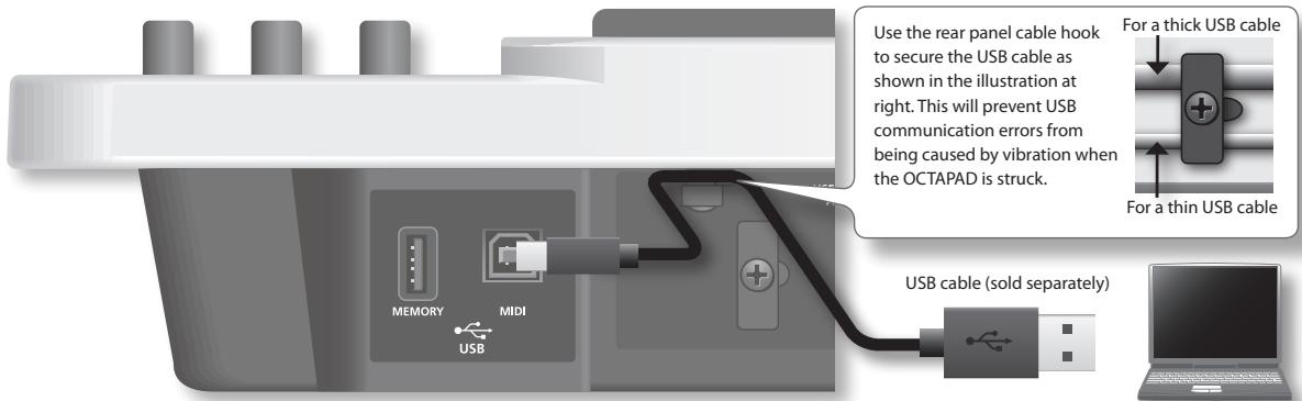
* For details on operating requirements, refer to the Roland website.
Roland website
Here you can download the original driver, and view installation instructions and operating requirements.
http://www.roland.com/
NOTE
- Only MIDI data can be transmitted or received via USB.
- Power-on the OCTAPAD before starting the MIDI application on your computer. Do not turn the OCTAPAD's power on or off while your MIDI application is running.
USB driver settings
Normally it will not be necessary to install a USB driver in your computer. However if you experience problems with the computer connection (if a malfunction occurs, or if the performance is poor), you may be able to solve the problem by downloading and installing Roland's original driver as described below.
- In the OCTAPAD's SYSTEM-MIDI screen, change the "USB Driver" (p. 65) setting to "VENDER."
- Turn the OCTAPAD's power off, and then on again.
- Download and install the original Roland driver.
For details on downloading and installing the original Roland driver, refer to the Roland website.
Internal Pad Settings (PAD SETTING-INTERNAL)
Here's how to adjust the sensitivity of the internal pads.
- Choose MENU → PAD → INTERNAL (p. 16).
The PAD SETTING-INTERNAL screen appears. - Hit a pad to select the pad whose settings you want to edit.
- Turn [Knob 1] (SEL) to select a parameter.
- Turn [Knob 3] (- / + ) to edit the value.
The following parameters are common to pads 1–8.
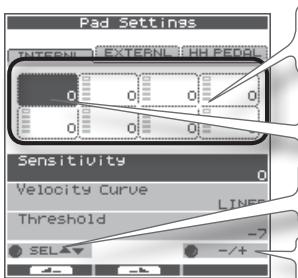
Trigger meter.
This indicates the velocity value.
Hit a pad to select the pad whose settings you want to edit.
[Knob 1] (SEL) selects a parameter.
[Knob 3] (- / + ) edits the value.
| Parameter | Value | Explanation | |
| Sensitivity | -9-+9 | You can adjust the sensitivity of the pads to accommodate your personal playing style.This allows you to have more dynamic control over the sound volume, based on how hard you play. Higher sensitivity allows the pad to produce a loud volume even when played softly. Lower sensitivity will keep the pad producing a low volume even when played forcefully. | |
| Velocity Curve | Adjust this curve until the response feels as natural as possible. | ||
| LINEAR | The standard setting. This produces the most natural correspondence between playing dynamics and volume change. | 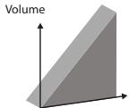 LINEARD playingDynamics LINEARD playingDynamics | |
| EXP1, EXP2 | Compared to LINEAR, strong dynamics produce a greater change. | Volu   EXP1 PlayingDynamics EXP2 PlayingDynamics EXP1 PlayingDynamics EXP2 PlayingDynamics | |
| LOG1, LOG2 | Compared to LINEAR, a soft playing produces a greater change. | Volu   LOG1 PlayingDynamics LOG2 PlayingDynamics LOG1 PlayingDynamics LOG2 PlayingDynamics | |
| SPLINE | Extreme changes are made in response to playing dynamics. | Volu  SPLINE layingDynamics SPLINE layingDynamics | |
| LOUD1, LOUD2 | Very little dynamic response, making it easy to maintain strong volume levels.If you're using a drum trigger as an external pad, these settings will produce reliable triggering. | Volu   LOUD1 PlayingDynamics LOUD2 PlayingDynamics LOUD1 PlayingDynamics LOUD2 PlayingDynamics | |
| Threshold | -9-+9 | This setting allows a trigger signal to be received only when the pad is above a determined dynamic level (velocity). This can be used to prevent a pad from sounding because of vibrations from other pads.In the following example, B will sound but A and C will not sound.ThresholdWhen set to a higher value, no sound is produced when the pad is struck lightly. Gradually raise the "Threshold" value while striking the pad.Check this and adjust accordingly. Repeat this process until you get the perfect setting for your playing style. | |
Connecting Optional Pads or Pedals
The OCTAPAD lets you connect a hi-hat control pedal (FD-8), kick trigger or pads to the external trigger inputs. The illustration below shows a typical set of connections, but there are many possibilities; like connecting two kick pedals to the 1/KICK input and the 2/SNARE input.
After connecting any external pads or pedals, you need to set the appropriate Pad Type as described below.
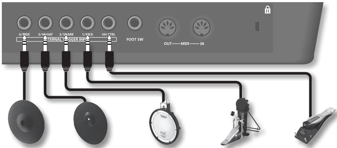
| 4/RIDE | 3/HI-HAT | 2/SNARE | 1/KICK | HH CTRL |
| V-cymbal(e.g., CY-12R/C) | Cymbal pad(e.g., CY-5) | V-pad(e.g., entire PD series) | Kick trigger pad(e.g., KD-8, KD-7) | Hi-hat control pedal(FD-8, VH-11) |
* To make connections, use the cable included with each pad.
External Pad Settings (PAD SETTING-EXTERNAL)
Here's how to make settings for external pads.
1. Choose MENU → PAD → EXTERNAL (p. 16).
The PAD SETTING-EXTERNAL screen appears.
![Hit a pad to select the pad whose settings you want to change. Trigger meter, and type of each pad. [Knob 1] (SEL) selects a parameter. Pad Settings INTERNL EXTERNAL HH PE600 BANK [1] NAME: Micro Drum Setup KD85 P120 PDX8 CY15 Pad Type KD-85 Sensitivity Threshold SEL BANK NAME.. Three sets of external pad settings can be stored (banks 1–3). Turn [Knob 2] (BANK) to change banks. Press [Button 3] (NAME) to go to a screen where you can assign a bank name (p. 35). Turn [Knob 3] (-/+) to edit the value.](/content/2025/01/130963/images/384f1ab902318bb0ff26e1a351d4a0d80505f40e6a88e9fe023c8f25df50cd9d.jpg)
- Hit an external pad (or step on a pedal) to select the pad whose settings you want to edit.
- Turn [Knob 1] (SEL) to select a parameter.
- Turn [Knob 3] (-/+) to edit the value.
About banks
You can store three different external pad configurations. These are called Banks (banks 1–3). Turn [Knob 2] (BANK) to change banks. Press [Button 3] (NAME) to access the screen where you can name the specific bank (p. 35).
Specifying the External Pad Type (PAD TYPE)
The "Pad Type" is a set of various pad-related parameters corresponding to specific pads. Those parameters are set to their appropriate values automatically upon selecting the "Pad Type."
If the pad's response is not as you wished, then you can still make fine adjustments to the pad parameters in order to adapt to your playing dynamics.
| Parameter | Value | Explanation |
| Pad Type | KD-7, KD-8, KD-85, KD-120, KD-140, PD-8, PDX-6, PDX-8, PD-85, PD-105, PD-105X, PD-125, PD-125X, CY-5, CY-8, CY-14C, CY-12R/C, CY-15R, VH-11, RT-10K, RT-10S, RT-10T | For each Pad, you can select the type of pad you're using (the pad type) so the OCTAPAD will accurately receive the signal from the pad. |
Adjusting the External Pad Sensitivity
When you specify the pad type, the following settings are automatically set to the values appropriate for each pad, meaning that you will normally not need to adjust them. If you wish to make detailed adjustments, you can edit the following parameters.
| Parameter | Value | Explanation | |
| Sensitivity | 1-32 | Refer to the explanation for "Sensitivity" (p. 59). | |
| Threshold | 0-16 | Refer to the explanation for "Threshold" (p. 59). | |
| Velocity Curve | LINEAR, EXP1, EXP2, LOG1, LOG2, SPLINE, LOUD1, LOUD2 | Refer to the explanation for "Velocity Curve" (p. 59). | |
| Scan Time (ms) | 0.1-4.0 | Specifies the detection time for the trigger signal.Since the rise time of the trigger signal waveform may differ slightly depending on the characteristics of each pad or acoustic drum trigger (drum pickup), you may notice that identical hits (velocity) may produce sound at different volumes. If this occurs, you can adjust the "Scan Time" so that your way of playing can be detected more precisely.While repeatedly hitting the pad at a constant force, gradually raise the Scan Time value from 0.1 msec, until the resulting volume stabilizes at the loudest level. At this setting, try both soft and loud hits, and make sure that the volume changes appropriately.* As the value is set higher, the time it takes for the sound to be played increases. Set this to the lowest value possible. | 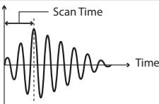 |
| Retrigger Cancel | 1-16 | This setting prevents spurious re-triggering Important if you are using acoustic drum triggers. Such triggers can produce altered waveforms, which may also cause inadvertent sounding at Point A in the figure (Re-trigger). This occurs in particular at the decaying edge of the waveform. Retrig Cancel detects such distortion in and prevents re-triggering from occurring.While repeatedly striking the pad, raise the "Retrig Cancel" value until re-triggering no longer occurs.* Although setting this to a high value prevents retriggering, it then becomes easy for sounds to be omitted when the drums played fast (roll etc.). Set this to the lowest value possible while still ensuring that there is no retriggering.MEMOYou can also eliminate this problem of re-triggering with the Mask Time setting. Mask Time does not detect trigger signals if they occur within the specified amount of time after the previous trigger signal was received. Re-trigger Cancel detects the attenuation of the trigger signal level, and triggers the sound after internally determining which trigger signals were actually generated when the head was struck, while weeding out the other false trigger signals that need not trigger a sound. | 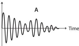 |
| Mask Time (ms) | 0-64 | This setting prevents double triggering.When playing a kick trigger, the beater can bounce back and hit the head a second time immediately after the intended note—with acoustic drums sometimes the beater stays against the head—is causes a single hit to "double trigger" (two sounds instead of one). The Mask Time setting helps to prevent this. Once a pad has been hit, any additional trigger signals occurring within the specified "Mask Time" (0-64 msec) will be ignored.Adjust the "Mask Time" value while playing the pad.When using a kick trigger, try to let the beater bounce back and hit the head very quickly, then raise the "Mask Time" value until there are no more sounds made by the beater rebound.* When set to a high value, it will be difficult to play very quickly. Set this to as low a value as you can.MEMOIf two or more sounds are being produced when you hit the head just once, then adjust Retrigger Cancel. | 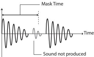 |
| Parameter | Value | Explanation |
| X-Talk Cancel Rate(%) | 0–80 | This setting cancels “crosstalk,” which means that when you play one pad you hear a sound coming from another pad. This can happen when two pads are installed on the same stand. In some cases you can prevent crosstalk by increasing the distance between the two mounted pads.MEMOIn some cases you can prevent crosstalk by increasing the distance between the two mounted pads. |
| Crosstalk Example: If you hit the 2/SNARE pad and the 3/HI-HAT also soundsWhile striking the 2/SNARE pad, gradually increase the “XTalk Cancel” value for the 3/HI-HAT pad until the 3/HI-HAT pad no longer sounds when you hit the 2/SNARE pad. Raise the “Xtalk Cancel” for the pad being used for 3/HI-HAT. The 3/HI-HAT pad will be less prone to receive crosstalk from other pads.* If the value is set too high, and two pads are played simultaneously, the one that is struck less forcefully may not sound. Be careful and set this parameter to the minimum value required to prevent crosstalk. | ||
| Rim Gain | 0.0–8.0 | When a PD-125/120/105/85/80R, PDX-8, PD-9/8/7, CY series pad, VH-11, or RT-10S is connected, you can adjust the relation between your playing velocity (force) on the rim/edge and the resulting volume level.Higher value allows the rim/edge to produce a loud volume even when played softly.Lower value will keep the rim/edge producing a low volume even when played forcefully. |
| Rim Adjust | 0.0–8.0 | When a PD-125/120/105/85/80R, PDX-8, or RT-10S is connected, you can adjust the sensitivity of the rim response. There are some cases that you have a rim sound unexpectedly when you hit the head strongly. You can improve this situation with decreasing the value of “Rim Adjust.” When you set the value too small, it might be difficult to play the rim sound. |
External Hi-Hat Pedal Settings (PAD SETTING-HH PEDAL)
Here's how to make settings for an optional, external hi-hat control pedal (FD-8 or VH-11).
1. Choose MENU → PAD → HH PEDAL (p. 16).
The PAD SETTING-HH PEDAL screen appears.
![Pad Settings INTERNAL : EXTERNAL : HH PEDAL HH Pedal Sens -1 FD-8 OP CL Pedal Calibration Indicator If Pad Type is set to "VH-11," a pedal calibration indicator for the VH-11 is shown. For types other than the VH-11, the indication will be for the FD-8. [Knob 3] (-/+) edits the value.](/content/2025/01/130963/images/5338381e93db447cdf2469aed04dec60bed2c7dcb74c1dd4fd73c65d73eee77f.jpg)
2. Turn [Knob 3] (−/+) to edit the value.
| Parameter | Value | Explanation |
| HH Pedal Sens | -10→+10 | Adjusts the sensitivity for playing foot-close or foot-splash notes. Positive (“+”) settings allow louder sounds to be produced even when you step lightly on the pedal. |
* If you connect an external hi-hat control pedal, set the "HH CTRL" (p. 32) parameter of the hi-hat Inst to "PEDAL."
VH-11 Offset Adjustment
If you're using a V-hi-hat (VH-11: sold separately), make adjustments by turning the VH-11's VH offset adjustment screw while watching the indicator shown in the right side of the screen.
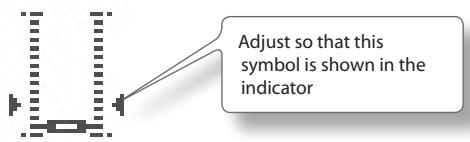
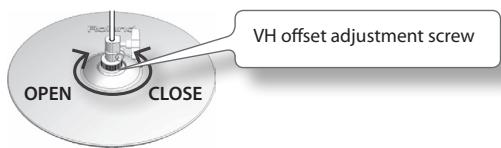
Offset Adjustment Points
If the closed hi-hat sound is difficult to attain, rotate the VH offset adjustment screw towards "CLOSE." If the open hi-hat sound is difficult to attain, rotate the screw towards "OPEN." If the sound cuts off when you hit the hi-hat forcefully, rotate the VH Offset adjustment screw towards "OPEN."
About MIDI
MIDI stands for Musical Instrument Digital Interface, and is a global standard that allows electronic musical instruments and computers to exchange performance data.
"MIDI Implementation Chart" (p. 70) is a chart that provides an easy way of checking which MIDI messages the OCTAPAD is able to receive. By comparing the MIDI implementation charts of the OCTAPAD and some other MIDI device, you can see which messages are compatible between the two devices.
MIDI Settings for a Kit (KIT MIDI)
Here's how to make MIDI settings for each individual kit.
1. Choose MENU → MIDI (p. 16).
The KIT MIDI screen appears.
For the CH, NOTE, or G.TIME tabs
![[Knob 1] (PAD SEL) selects the pad that you want to edit. KIT 01: OCTAPAD KIT MIDI HIHAT KNOB CH NOTE# G.TIME Value of each pad (Inst A is above, Inst B is below) Value of external trigger inputs 1–4 (Head is above, Rim is below) [Knob 2] (B) edits the Inst B (Rim) value. [Knob 3] (A) edits the Inst A (Head) value.](/content/2025/01/130963/images/261bc4b000c1f29da61f0c75d34e760888ab066905b1402d692792d07f920438.jpg)
| Parameter | Value | Explanation |
| CH tab | ||
| CH | GBL, 1–16, OFF | MIDI channel on which each pad will transmit note messages.If this is “OFF,” MIDI messages will not be transmitted. If this is “GBL,” MIDI messages will be transmitted on the “Global Channel” (p. 65) specified by the system settings.MEMOThe MIDI channel in Phrase Loop mode is specified by “Part 1–3 MIDI Ch.” (p. 51). |
| NOTE# tab | ||
| NOTE# | OFF, 0–127 | MIDI note number transmitted by each pad.Pads with conflicted note number with other pad are indicated by a “*” symbol in the screen. |
| G.TIME tab | ||
| G.TIME | 0.1–8.0, ALT | Duration of the notes transmitted by each pad.The gate time corresponds to the time between when a key is pressed and released on a MIDI keyboard (the time between note-on and note-off). You can specify a gate time in the range of 0.1 seconds to 8.0 seconds. If you choose ALT (Alternate), note-on and note-off messages will be transmitted alternately each time you hit the pad. |
For the HIHAT or KNOB tabs
[Knob 1] (SEL) selects a parameter.
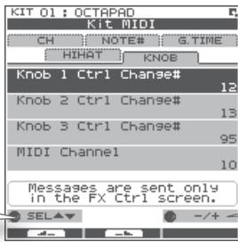
[Knob 3] (−/+) edits the value.
| Parameter | Value | Explanation |
| HIHAT tab | ||
| HH Close Note# A | OFF, 0–127 | MIDI note number transmitted by closed hi-hat Inst A (Head). With the "OFF" setting, MIDI messages will not be transmitted. |
| HH Close Note# B | OFF, 0–127 | MIDI note number transmitted by closed hi-hat Inst B (Rim). With the "OFF" setting, MIDI messages will not be transmitted. |
| HH Pedal Note# | OFF, 0–127 | MIDI note number transmitted by the pedal hi-hat. With the "OFF" setting, MIDI messages will not be transmitted. |
| Pedal Ctrl Change# | OFF, 1–5,7–31, 64–95 | Specifies the control change message that will be transmitted and received as MIDI data indicating the depth to which the hi-hat pedal is pressed. With the "OFF" setting, MIDI messages will not be transmitted. |
| Pedal Compatibility | GENERAL | Choose this setting if you're using an external MIDI sound module other than the V-Drums series. |
| V-DRUMS | Choose this setting if you're using a V-Drums series MIDI sound module such as the TD-20 or TD-9. MIDI messages appropriate for the V-Drums series will be transmitted. | |
| KNOB tab | ||
| Knob1 Ctrl Change# | OFF, 1–5,7–31, 64–95 | The control change message you specify here will be transmitted when you turn [Knob 1]–[Knob 3] on the FX CONTROL screen. With the "OFF" setting, MIDI messages will not be transmitted. |
| Knob2 Ctrl Change# | OFF, 1–5,7–31, 64–95 | |
| Knob3 Ctrl Change# | OFF, 1–5,7–31, 64–95 | |
| Knob MIDI Channel | GLOBAL, 1–16, OFF | When you turn [Knob 1]–[Knob 3], control change messages will be transmitted on the transmit channel you specify here. With the "OFF" setting, MIDI messages will not be transmitted. With the "GLOBAL" setting, MIDI messages will be transmitted on the "Global Channel" (p. 65) specified by the system settings. |
KIT MIDI Screen QUICK MENU
From the KIT MIDI screen, press the [QUICK] button to access the following QUICK MENU.
| Menu | Explanation |
| Copy Kit MIDI | Copies the Kit MIDI settings. |
| Paste Kit MIDI | Pastes the Kit MIDI settings. You can paste to a different kit. |
| Kit Protect ON/OFF | Turns the Kit Protect setting (p. 34) on/off. |
System MIDI Settings (SYSTEM-MIDI)
Here you can make overall MIDI settings for the entire OCTAPAD.
1. Choose MENU → SYSTEM → MIDI (p. 16).
The SYSTEM-MIDI screen appears.
![[Knob 1] (SEL) selects a parameter. System INFO F.RESET OPTIONS CONTROL MIDI Global Channel 10 MIDI Sync INT Local Control ON MIDI In -> Out Thru OFF Transmit & receive channel of entire OctaPad. SEL +/- + -/+ [Knob 3] (-/+) edits the value.](/content/2025/01/130963/images/d57f92ba3c7d9cca315f9f6bfc7ea6cae2a0abffec082c9f3b6bcb78ccb81521.jpg)
| Parameter | Value | Explanation |
| Global Channel | OFF, 1–16 | Specifies the transmit/receive channel.With the “OFF” setting, MIDI messages will not be transmitted. |
| MIDI Sync | Specifies how the OCTAPAD’s phrase playback tempo will be synchronized. | |
| AUTO | When MIDI Clock messages (F8) are received at the MIDI IN connector or the USB MIDI connector, the OCTAPAD will automatically detect them and synchronize to their tempo. | |
| INT | The OCTAPAD will synchronize to its own internal clock. MIDI Clock messages received from the MIDI IN connector or USB MIDI connector will be ignored. | |
| MIDI | Operation will be the same as for AUTO, but MIDI Clock from the USB MIDI connector will be ignored. | |
| USB | Operation will be the same as for AUTO, but MIDI Clock from the MIDI IN connector will be ignored. | |
| Local Control | OFF, ON | Turns the Local Control setting on/off.Local Control is a setting used when you’re recording your pad performance onto an external MIDI sequencer.When you’re recording and Local Control is “OFF,” the performance data produced when you hit a pad will not be sent directly to the OCTAPAD’s internal sound generator; it will be sent through your external sequencer. |
| MIDI In -> Out Thru | OFF, ON | If this is “ON,” data received at MIDI IN connector will be re-transmitted from MIDI OUT connector. |
| USB -> MIDI-Out Thru | OFF | If this is “ON,” incoming MIDI messages will be re-transmitted without change from the MIDI OUT connector. |
| USB Driver | Specifies the USB driver mode.If you change this setting, you must power-off the OCTAPAD and turn it back on again. | |
| GENERIC | Choose this if you’re using the standard USB driver provided by your computer.Normally you’ll use this mode. | |
| VENDER | Choose this if you’re using the USB driver downloaded from the Roland website. | |
| Prog Change TX | OFF, ON | Specifies whether program change messages will be transmitted (ON) to an external MIDI device or not transmitted (OFF).If this is “ON,” when you switch kits on the OCTAPAD, the program number assigned to the newly selected kit will be transmitted. |
| Prog Change RX | OFF, ON | Specifies whether program change messages sent from an external MIDI device will be received (ON) or not received (OFF).If this is “ON,” the OCTAPAD will switch to the kit that corresponds to the received program number. |
| Ctrl Change Tx | OFF, ON | Specifies whether control change messages will be transmitted to an external MIDI device (ON) or not transmitted (OFF). |
| Ctrl Change Rx | OFF, ON | Specifies whether control change messages sent from an external MIDI device will be received (ON) or not received (OFF). |
| Device ID | 17–32 | When transmitted or receiving system exclusive messages, set this to match the device ID numbers of the two units. |
What is V-LINK?
V-LINK (V-LINK) is a function that allows a musician to make visual performances with images at the same time he or she is performing music. By using MIDI to connect two or more V-LINK compatible devices, you can easily enjoy performing, in real time, a wide range of visual effects that are linked to the expressive aspects of a your performance. For example, if you use the OCTAPAD in conjunction with the EDIROL P-10, you'll be able to do the following.
- Switch images by striking the OCTAPAD's pads.
- Control the images and their effects by using the OCTAPAD's three knobs.
Connection example
This example shows the OCTAPAD connected to an EDIROL P-10. Use a MIDI cable to connect the OCTAPAD's MIDI OUT connector to the EDIROL P-10's MIDI IN connector.
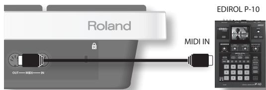
V-LINK Settings (V-LINK SETTINGS)
Here's how to make V-LINK settings.
1. Choose MENU → V-LINK (p. 16).
The V-LINK SETTINGS screen appears.
CLIP tab
![[Knob 1] (PAD SEL) selects the pad to be edited. Value for each pad (FUNC/BANK value is above, CLIP value is below) [Knob 2] (BANK) edits the FUNC/BANK value. [Knob 3] (CLIP) edits the CLIP value.](/content/2025/01/130963/images/b76c690c5daf9a6273d24d11ee50dd4e7b1857c417cee0e97b29fcc069e0ba13.jpg)
| Parameter | Value | Explanation |
| BANK | BK00-BK99 | Bank number |
| CLIP | 00-99 | Clip number |
SETUP tab
Use [Knob 1] (SEL) to select a parameter. Use [Knob 3] (-/+) to edit the value.
| Parameter | Value | Explanation |
| V-Link Channel | 1–16 | MIDI channel used to control V-LINK devices when V-LINK is on. |
| Knob1 CC# (Speed) | OFF, 1–95 | Specifies the CC# that will be transmitted when you turn the three knobs in the FX CONTROL screen that appears when you press [FX CTRL] button. |
| Knob2 CC# (Color) | ||
| Knob3 CC# (Fade) |
Turning V-LINK On/Off
1. Press the [V-LINK] button to make it light.
V-LINK will turn on.
2. Press the [V-LINK] button once again.
The [V-LINK] button will go dark, and V-LINK will turn off.
Appendix
This chapter contains a list of error messages, main specifications, and troubleshooting information.

| Message | Meaning | Action |
| MIDI-related error messages | ||
| MIDI Offline. | The MIDI cable or USB cable was disconnected. Alternatively, communication with the external MIDI device has been interrupted for some reason. | Check whether the MIDI cable or USB cable could have been disconnected or broken. |
| MIDI Buffer Full. | A large amount of MIDI messages was received in a short time, and the OCTAPAD was unable to process them all. | Make sure that the external MIDI device is correctly connected. If this does not solve the problem, decrease the amount of MIDI messages being transmitted to the OCTAPAD. |
| Transmit buffer full. | An excessive amount of data was transmitted from the OCTAPAD, and could not be correctly output from MIDI OUT connector. | Decrease the amount of data being transmitted, for example by decreasing the recorded Phrase Loop data. |
| USB-related error messages | ||
| Can not access to the USB memory. | USB memory is not connected. | Connect USB memory to the USB memory connector. |
| Could not read this file. | The specified data was not found in the USB memory. Alternatively, the saved data is damaged. | Check the USB memory. |
| USB Memory Full. | There is insufficient free space on the USB memory. | Delete unneeded data. |
| Check USB memory. | The USB memory is not working correctly. | Check the USB memory. |
| Remove the USB device. | A USB device that the OCTAPAD cannot handle is connected, or a foreign object may have entered the USB memory connector, causing a short circuit. | Immediately disconnect the connection, and check that no foreign object has entered the USB memory connector. |
| PHRASE LOOP-related error messages | ||
| Phrase Memory full. | The Phrase Loop memory area is full. | Save your data to USB memory (p. 49), and create a new phrase. |
| System-related error messages | ||
| Device error. | There is a problem with the internal system. | Please contact your dealer. |
| Data memory was damaged. | There is a problem with internal memory. | A factory reset will be executed automatically. |
Specifications
SPD-30: OCTAPAD
| Pads | Built-in Pads: 8* Four external trigger inputs are provided, allowing you to connect Pads. |
| Kits | 50 |
| Kit Chain | 8 chains (20 steps per chain) |
| Instrument Parameters | TuningMufflingSoft AttackTone ColorPitch SweepVolumePanReverse |
| Effect Types | Ambience (7 Types)EqualizerLimiterMulti Effect (30 Types) |
| Phrase Loop | Phrases: 50Parts: 3Tempo: 40–260Resolution: 480 ticks per quarter noteRecording Method: Real-timeMaximum Note Storage: approx. 10,000 Notes |
| Display | 160 x 160 dots Graphic Type LCD (Backlit LCD)Pad Status Illumination x 8 (LED) |
| Connectors | PHONES Jack (Stereo 1/4 inch phone type)OUTPUT Jacks (L (MONO), R) (1/4 inch phone type)MIX IN Jack (Stereo 1/4 inch phone type)EXTERNAL TRIGGER INPUT Jacks x 4HH CTRL JackFOOT SW Jack (1/4 inch TRS phone type)MIDI Connectors (IN, OUT)USB MEMORY Connector (for USB Memory)USB MIDI Connector (for USB MIDI) |
| Output Impedance | 1.0 k ohms |
| Power Supply | AC Adaptor (DC 9 V) |
| Current Draw | 600 mA |
| Dimensions | 540.8 (W) x 272.4 (D) x 87.6 (H) mm21-5/16 (W) x 10-3/4 (D) x 3-1/2 (H) inches |
| Weight | 3.8 kg / 8 lbs 7 oz (excluding AC Adaptor) |
| Accessories | Owner's ManualAC Adaptor (PSB-1U)Screws (M5 x 12 mm) x 4 |
| Options | Pads (PD series, PDX series)Cymbals (CY series)Kick Triggers (KD series)Hi-Hats (VH-11)Hi-Hat Control Pedal (FD series)Pad Stand (PDS-10)All-Purpose Clamp (APC-33)Acoustic Drum Trigger (RT-10K, RT-10S, RT-10T)Pedal Switch (DP-2)Foot Switch (FS-5U, FS-6)Personal Drum Monitor: PM-10, PM-30V-Drums Accessory Package: DAP-3V-Drums Mat: TDM-10USB memory* Use USB memory sold by Roland. We cannot guarantee operation if other products are used. |
* In the interest of product improvement, the specifications and/or appearance of this unit are subject to change without prior notice.
| Problem | Items to check | Action |
| No sound / Insufficient volume | Is the OCTAPAD and the connected equipment powered-on? | Use the dedicated AC adaptor. |
| Is the OCTAPAD correctly connected to the external devices? | Check the connections. | |
| Could an audio cable be broken? | Try using a different cable. | |
| Could the volume of the connected amp or mixer be lowered? | Adjust the volume to an appropriate level. | |
| Could the OCTAPAD's volume ([MASTER] knob, [PHONES] knob) be lowered? | Adjust the volume to an appropriate level. | |
| Check whether you hear sound through headphones. | If you hear sound in the headphones, there is a problem with the connection cables or with the connected amp or mixer. Check the connected devices and the connections. | |
| No sound or insufficient volume from a device connected to the MIX IN connector | Could the volume be lowered on the device connected to the MIX IN connector? | Adjust the volume to an appropriate level. |
| Is the audio cable connected correctly? | Check the connection. | |
| Could the audio cable be broken? | Try using a different cable. | |
| USB memory is inserted, but is not detected / Can-not select data | Is the USB memory inserted correctly? | Check the USB memory. |
| Is the USB memory of a correct type? | Use USB memory sold by Roland. Operation is not guaranteed if other products are used. | |
| Is the USB memory formatted correctly? | Use the OCTAPAD to format the USB memory (p. 55). | |
| Data was not saved correctly to USB memory | The power may have been turned off while writing data to USB memory (i.e., while the USB memory access indicator was blinking). The lost data cannot be recovered. | In this state, it is possible that all data in USB memory was damaged. Additional malfunctions may occur if you continue using it, so format the USB memory (p. 55). When you format USB memory, all its data will be lost. |
| The OCTAPAD's tempo does not synchronize to the tempo of an external MIDI device | Has the OCTAPAD been set correctly for synchronization? | Check the "MIDI Sync" (p. 65) setting. |
| Is your external MIDI device set to transmit MIDI clock messages? | Some devices have a MIDI clock transmission setting (on/off). Alternatively, some external sequencers may transmit MIDI clock only while that device is playing. | |
| Display contrast is inconsistent | In some cases, the contrast of the display might not be consistent, but this is not a malfunction. Adjust the contrast. | Adjust "LCD Contrast" (p. 52) to minimize the inconsistency in the contrast. |
Attaching the Stand (Sold Separately)
Use the screws on the bottom of the OCTAPAD to attach a stand holder as shown in the illustration. Then attach the OCTAPAD to your pad stand (sold separately: PDS-10 * You can also attach it to the APC-33 all purpose clamp). For details on how to assemble the pad stand, or how to attach the stand holder, refer to the owner's manual of the pad stand.
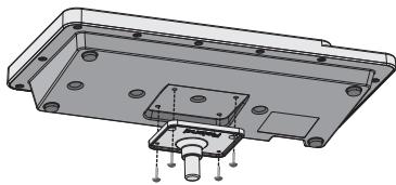
natural_image
Technical drawing of a mechanical housing component with mounting holes and mounting brackets (no text or symbols)* Use only the screws that are on the bottom panel. Using any other screws will cause malfunctions.
* When turning the OCTAPAD upside down, take care not to damage its buttons or knobs, and handle it with care to avoid letting it drop or fall over.
(Sound Generator Section)
Date : Jan. 1, 2010
Model OCTAPAD (SPD-30)
Version : 1.00
| Function... | Transmitted | Recognized | Remarks | |
| Basic Channel | Default Changed | 1-16, OFF1-16, OFF | 1-16, OFF1-16, OFF | Retained even while power is off. |
| Mode | Default Messages Altered | Mode 3X********** | Mode 3X********** | |
| Note Number: | True Voice | 0-127********** | 0-1270-127 | |
| Velocity | Note On Note Off | O 9nH, v=1-127O 8nH, v=1-127 | OX | |
| After Touch | Key's Channel's | OX | OX | |
| Pitch Bend | X | X | ||
| Control Change | 0, 321-567-3133-6364-95 | O *2O *1 *2O *2 *3O *1 *2O *2 *3O *1 *2 | O *2O *1 *2O *1 *2O *1 *2O *1 *2 | Bank select |
| Program Change : True Number | O *2********** | O *20-4950-99 *3 | Program Number1-50 | |
| System Exclusive | O | O | ||
| System Common | : Song Position: Song Select: Tune Request | XXX | XXX | |
| System Real Time | : Clock: Commands | OX | OX *4 | |
| Aux Messages | : All Sound Off: Reset All Controllers: Local On/Off: All Notes Off: Active Sensing: System Reset | XXXXXO X | OOXO (123-127)OX | |
| Notes | *1 Available controller numbers can be used to receive/transmit data describing the position of the hi-hat pedal and the values of knobs 1-3.*2 O X is selectable.*3 Can be transmitted only when V-LINK is ON.*4 Received when MIDI Sync is not set to INT. | |||
Mode 1 : OMNI ON, POLY
Mode 2 : OMNI ON, MONO
O: Yes
Mode 3 : OMNI OFF, POLY
Mode 4 : OMNI OFF, MONO
X: No
Model OCTAPAD (SPD-30)
Version : 1.00
| Function... | Transmitted | Recognized | Remarks | |
| Basic Channel | Default Changed | 1-16, OFF1-16, OFF | XX | Retained even while power is off. |
| Mode | Default Messages Altered | Mode 3X********** | XXX********** | |
| Note Number: | True Voice | 0-127********** | XX | |
| Velocity | Note On Note Off | O 9pH, v=1-127O 8pH, v=1-127 | XX | |
| After Touch | Key's Channel's | OX | XX | |
| Pitch Bend | X | X | ||
| Control Change | 1-567-3133-6364-95 | OOO*1 *2*2 *3*1 *2*2 *3*1 *2 | XXXX | |
| Program Change: True Number | XX | X | ||
| System Exclusive | X | X | ||
| System Common | : Song Position: Song Select: Tune Request | XXX | XXX | |
| System Real Time | : Clock: Commands | OO*5 | OO*4*6 | |
| Aux Messages | : All Sound Off: Reset All Controllers: Local On/Off: All Notes Off: Active Sensing: System Reset | XXXXXX | XXXXXX | |
| Notes | *1 Available controller numbers can be used to receive/transmit data describing the position of the hi-hat pedal and the values of knobs 1-3.*2 O X is selectable.*3 Can be transmitted only when V-LINK is ON.*4 Received when MIDI Sync is not set to INT.*5 Transmitted when Tx Start/Stop is ON.*6 Received when Rx Start/Stop is ON. | |||
Mode 1 : OMNI ON, POLY
Mode 2 : OMNI ON, MONO
O: Yes
Mode 3 : OMNI OFF, POLY
Mode 4: OMNI OFF, MONO
X: No
INSTRUCTIONS FOR THE PREVENTION OF FIRE, ELECTRIC SHOCK, OR INJURY TO PERSONS
About ⚠️ WARNING and ⚠️ CAUTION Notices
| WARNING | Used for instructions intended to alert the user to the risk of death or severe injury should the unit be used improperly. |
| CAUTION | Used for instructions intended to alert the user to the risk of injury or material damage should the unit be used improperly.* Material damage refers to damage or other adverse effects caused with respect to the home and all its furnishings, as well to domestic animals or pets. |
About the Symbols
| The △ symbol alerts the user to important instructions or warnings. The specific meaning of the symbol is determined by the design contained within the triangle. In the case of the symbol at left, it is used for general cautions, warnings, or alerts to danger. | |
| The Ⓧ symbol alerts the user to items that must never be carried out (are forbidden). The specific thing that must not be done is indicated by the design contained within the circle. In the case of the symbol at left, it means that the unit must never be disassembled. | |
| The ● symbol alerts the user to things that must be carried out. The specific thing that must be done is indicated by the design contained within the circle. In the case of the symbol at left, it means that the power-cord plug must be unplugged from the outlet. |
ALWAYS OBSERVE THE FOLLOWING
WARNING
Do not open (or modify in any way) the unit or its AC adaptor.

Do not attempt to repair the unit, or replace parts within it (except when this manual provides specific instructions directing you to do so). Refer all servicing to your retailer, the nearest Roland Service Center, or an authorized Roland distributor, as listed on the "Information" page.

Never install the unit in any of the following locations.
- Subject to temperature extremes (e.g., direct sunlight in an enclosed vehicle, near a heating duct, on top of heat-generating equipment); or are
- Damp (e.g., baths, washrooms, on wet floors); or are
- Exposed to steam or smoke; or are
- Subject to salt exposure; or are
- Humid; or are
- Exposed to rain; or are
- Dusty or sandy; or are
- Subject to high levels of vibration and shakiness.
This unit should be used only with a stand that is recommended by Roland.


When using the unit with a stand recommended by Roland, the stand must be carefully placed so it is level and sure to remain stable. If not using a stand, you still need to make sure that any location you choose for placing the unit provides a level surface that will properly support the unit, and keep it from wobbling.

Be sure to use only the AC adaptor supplied with the unit. Also, make sure the line voltage at the installation matches the input voltage specified on the AC adaptor's body. Other AC adaptors may use a different polarity, or be designed for a different voltage, so their use could result in damage, malfunction, or electric shock.

Use only the attached power-supply cord. Also, the supplied power cord must not be used with any other device.

Do not excessively twist or bend the power cord, nor place heavy objects on it. Doing so can damage the cord, producing severed elements and short circuits. Damaged cords are fire and shock hazards!

WARNING
This unit, either alone or in combination with an amplifier and headphones or speakers, may be capable of producing sound levels that could cause permanent hearing loss. Do not operate for a long period of time at a high volume level, or at a level that is uncomfortable. If you experience any hearing loss or ringing in the ears, you should immediately stop using the unit, and consult an audiologist.
Do not allow any objects (e.g., flammable material, coins, pins); or liquids of any kind (water, soft drinks, etc.) to penetrate the unit.


Immediately turn the power off, remove the AC adaptor from the outlet, and request servicing by your retailer, the nearest Roland Service Center, or an authorized Roland distributor, as listed on the "Information" page when:
- The AC adaptor, the power-supply cord, or the plug has been damaged; or
• If smoke or unusual odor occurs - Objects have fallen into, or liquid has been spilled onto the unit; or
- The unit has been exposed to rain (or otherwise has become wet); or
- The unit does not appear to operate normally or exhibits a marked change in performance.
In households with small children, an adult should provide supervision until the child is capable of following all the rules essential for the safe operation of the unit.
Protect the unit from strong impact. (Do not drop it!)


Do not force the unit's power-supply cord to share an outlet with an unreasonable number of other devices. Be especially careful when using extension cords-the total power used by all devices you have connected to the extension cord's outlet must never exceed the power rating (watts/amperes) for the extension cord. Excessive loads can cause the insulation on the cord to heat up and eventually melt through.
Before using the unit in a foreign country, consult with your retailer, the nearest Roland Service Center, or an authorized Roland distributor, as listed on the "Information" page.


CAUTION
The unit and the AC adaptor should be located so their location or position does not interfere with their proper ventilation.

This (OCTAPAD SPD-30) for use only with Roland stand PDS-10. Use with other stands is capable of resulting in instability causing possible injury.

CAUTION
Please be sure to read and adhere to the cautionary notices contained in the instructions that came with this product.

Please note that, depending on the manner in which performances are carried out, you may encounter situations where the stand topples over, even though you have followed all of the instructions and advice contained within the product's manual. For this reason, you should always perform a safety check each time you use the stand.
Always grasp only the plug on the AC adaptor cord when plugging into, or unplugging from, an outlet or this unit.

At regular intervals, you should unplug the AC adaptor and clean it by using a dry cloth to wipe all dust and other accumulations away from its prongs. Also, disconnect the power plug from the power outlet whenever the unit is to remain unused for an extended period of time. Any accumulation of dust between the power plug and the power outlet can result in poor insulation and lead to fire.

Try to prevent cords and cables from becoming entangled. Also, all cords and cables should be placed so they are out of the reach of children.

Never climb on top of, nor place heavy objects on the unit.

Never handle the AC adaptor or its plugs with wet hands when plugging into, or unplugging from, an outlet or this unit.

Before moving the unit, disconnect the AC adaptor and all cords coming from external devices.

If you need to move the instrument, take note of the precautions listed below.

Check to make sure the screws securing the unit to the stand have not become loose. Fasten them again securely whenever you notice any loosening.
- Disconnect the AC adaptor.
- Disconnect all cords coming from external devices.
Before cleaning the unit, turn off the power and unplug the AC adaptor from the outlet (p. 6).

Whenever you suspect the possibility of lightning in your area, disconnect the AC adaptor from the outlet.

Should you remove screws for the stand, keep them in a safe place out of children's reach, so there is no chance of them being swallowed accidentally.

Power Supply
- Do not connect this unit to same electrical outlet that is being used by an electrical appliance that is controlled by an inverter (such as a refrigerator, washing machine, microwave oven, or air conditioner), or that contains a motor. Depending on the way in which the electrical appliance is used, power supply noise may cause this unit to malfunction or may produce audible noise. If it is not practical to use a separate electrical outlet, connect a power supply noise filter between this unit and the electrical outlet.
- The AC adaptor will begin to generate heat after long hours of consecutive use. This is normal, and is not a cause for concern.
- Before connecting this unit to other devices, turn off the power to all units. This will help prevent malfunctions and/or damage to speakers or other devices.
Placement
- Using the unit near power amplifiers (or other equipment containing large power transformers) may induce hum. To alleviate the problem, change the orientation of this unit; or move it farther away from the source of interference.
- This device may interfere with radio and television reception. Do not use this device in the vicinity of such receivers.
- Noise may be produced if wireless communications devices, such as cell phones, are operated in the vicinity of this unit. Such noise could occur when receiving or initiating a call, or while conversing. Should you experience such problems, you should relocate such wireless devices so they are at a greater distance from this unit, or switch them off.
- Do not expose the unit to direct sunlight, place it near devices that radiate heat, leave it inside an enclosed vehicle, or otherwise subject it to temperature extremes. Excessive heat can deform or discolor the unit.
- When moved from one location to another where the temperature and/or humidity is very different, water droplets (condensation) may form inside the unit. Damage or malfunction may result if you attempt to use the unit in this condition. Therefore, before using the unit, you must allow it to stand for several hours, until the condensation has completely evaporated.
- Do not allow rubber, vinyl, or similar materials to remain on the unit for long periods of time. Such objects can discolor or otherwise harmfully affect the finish.
Maintenance
- For everyday cleaning wipe the unit with a soft, dry cloth or one that has been slightly dampened with water. To remove stubborn dirt, use a cloth impregnated with a mild, non-abrasive detergent. Afterwards, be sure to wipe the unit thoroughly with a soft, dry cloth.
- Never use benzine, thinners, alcohol or solvents of any kind, to avoid the possibility of discoloration and/or deformation.
Repairs and Data
- Please be aware that all data contained in the unit's memory may be lost when the unit is sent for repairs. Important data should always be backed up the USB memory, or written down on paper (when possible). During repairs, due care is taken to avoid the loss of data. However, in certain cases (such as when circuitry related to memory itself is out of order), we regret that it may not be possible to restore the data, and Roland assumes no liability concerning such loss of data.
Additional Precautions
- Please be aware that the contents of memory can be irretrievably lost as a result of a malfunction, or the improper operation of the unit. To protect yourself against the risk of loosing important data, we recommend that you periodically save a backup copy of important data you have stored in the USB memory.
- Unfortunately, it may be impossible to restore the contents of data that was stored on a USB memory once it has been lost. Roland Corporation assumes no liability concerning such loss of data.
- Use a reasonable amount of care when using the unit's buttons, sliders, or other controls; and when using its jacks and connectors. Rough handling can lead to malfunctions.
- Never strike or apply strong pressure to the display.
- When connecting / disconnecting all cables, grasp the connector itself-never pull on the cable. This way you will avoid causing shorts, or damage to the cable's internal elements.
- To avoid disturbing your neighbors, try to keep the unit's volume at reasonable levels. You may prefer to use headphones, so you do not need to be concerned about those around you (especially when it is late at night).
- This instrument is designed to minimize the extraneous sounds produced when it's played. However, since sound vibrations can be transmitted through floors and walls to a greater degree than expected, take care not to allow these sounds to become a nuisance to neighbors, especially when performing at night and when using headphones.
- When you need to transport the unit, package it in the box (including padding) that it came in, if possible. Otherwise, you will need to use equivalent packaging materials.
- Some connection cables contain resistors. Do not use cables that incorporate resistors for connecting to this unit. The use of such cables can cause the sound level to be extremely low, or impossible to hear. For information on cable specifications, contact the manufacturer of the cable.
Using USB memories
- Carefully insert the USB memory all the way in-until it is firmly in place.
- Never touch the terminals of the USB memory. Also, avoid getting the terminals dirty.
- USB memories are constructed using precision components; handle the cards carefully, paying particular note to the following.
- To prevent damage to the cards from static electricity, be sure to discharge any static electricity from your own body before handling the cards.
- Do not touch or allow metal to come into contact with the contact portion of the cards.
- Do not bend, drop, or subject cards to strong shock or vibration.
- Do not keep cards in direct sunlight, in closed vehicles, or other such locations (storage temperature: -25 to 85^ C ).
- Do not allow cards to become wet.
-
Do not disassemble or modify the cards.
-
MMP (Moore Microprocessor Portfolio) refers to a patent portfolio concerned with microprocessor architecture, which was developed by Technology Properties Limited (TPL). Roland has licensed this technology from the TPL Group.
- MatrixQuest™ 2010 TEPCO UQUEST, LTD. All rights reserved. The OCTAPAD's USB functionality uses MatrixQuest middleware technology from TEPCO UQUEST, LTD.
- Roland is a registered trademark of Roland Corporation in the United States and/or other countries.
- All product names mentioned in this document are trademarks or registered trademarks of their respective owners.

A
AC ADAPTOR 12
AMBIENCE 9, 25, 42
FOOTSW1, 2 POLARITY 54
FOOT SWITCH 43, 53
FUNCTION BUTTON 1-3 10
FUNCTION KNOB 1-3 10
FX 9,25,39
FX CONTROL 25,41
[FX CTRL] BUTTON 25,41
FX-EDIT 39
FX SEND 24,40
FX-SEND 40
FX-TYPE 39
G
GLOBAL CHANNEL 65
G.TIME 63
H
HH CLOSE NOTE# A, B 64
HH CTRL 32
HH PEDAL NOTE# 64
HH PEDAL SENS 62
HIGH 42
HI-HAT 32,64
HI-HAT CONTROL PEDAL 33, 62
|
ILLUMINATION 52
INSERT 37
INST 8, 23, 30
INST A, B 30
INST-EDIT 31
INST GROUPS 23
INST HEAD 31
INST-HH CTRL 32
INST-INST 30
INST LAYER TYPE 30
INST RIM 31
INTERNAL MEMORY 54
K
KIT 8,22
[KIT] BUTTONS 22
KIT CHAIN 37
KIT CHAIN ON/OFF 38
KIT LIST 22
KIT MIDI 63
KIT NAME 35
KIT OTHERS-KIT 34
KIT OTHERS-PHRASE 34
KIT PROTECT 34
KIT SCREEN 14, 22
KIT TEMPO 34
KIT TEMPO FUNC 52
KIT VOLUME 34
KNOB 64
KNOB1-3 CTRL CHANGE# 64
KNOB MIDI CHANNEL 64
L
LAYER 8,30
LAYER POINT 30
LCD BRIGHTNESS 52
LCD CONTRAST 52
LIMITER 42
LIST SCREEN 14
LOADING A PHRASE 50
LOCAL CONTROL 65
LOW 42
M
MASK TIME (MS) 61
[MASTER] KNOB 6
MEASURES 43, 51
MENU 16
[MENU] BUTTON 16
MID 42
MIDI 58,63
MIDI CH 51
MIDI IMPLEMENTATION CHART 70
MIDI IN -> OUT THRU 65
MIDI SYNC 65
MIX IN JACKS 12
MOVE DOWN 37
MOVE UP 37
MUFFLING 24, 31
MULTI EDIT 24
MUTE 46
[MUTE] BUTTON 46
MUTE GROUP 30
N
NAME 35
NEXT 47
NOTE 63
O
OUTPUT JACKS 12
P
PAD 11
PAD EXCHANGE 36
PAD SENSITIVITY 59
PAD SETTING-EXTERNAL 60
PAD SETTING-HH PEDAL 62
PAD SETTING-INTERNAL 59
PAD STATUS ILLUMINATION 11, 46,
47, 52
PAD TYPE 61
PAN 24, 31, 51
PART 44
PART 1-3 44
PART1-3 MIDI CH 51
PART LEVEL 48
PASTE 36
PASTE FX 40
PASTE KIT MIDI 64
PASTE NAME 35
PASTE PAD 35
PCS-31L 53
PDS-10 69
PEDAL 60
PEDAL COMPATIBILITY 64
PEDAL CTRL CHANGE# 64
PHONES JACK 12
[PHONES] KNOB 6
PHRASE LIST 50
PHRASE LOOP 9, 18, 26
PHRASE LOOP SETUP 51
PHRASE LOOP SETUP-CLICK 51
PHRASE LOOP STANDBY 44
PHRASE PLAY 34
PITCH SWEEP 24, 3
[PLAY] BUTTON 27
PLAY MODE 45
[POWER] BUTTON 6
PROG CHANGE RX 65
PROG CHANGE TX 65
PROGRAM VERSION 54
PROTECT 34,52
Q
QTZ 44
QUANTIZE 27,44
[QUICK] BUTTON 15
QUICK MENU 15, 33, 35, 37, 40, 44,
45, 50, 64
R
[REC] BUTTON 27
REC MODE 45
RESTORE ALL KITS 20
RESTORE ALL PHRASES 20
RESTORE ONE KIT 20
RETRIGGER CANCEL 61
REVERSE 24,31
RIM ADJUST 62
RIM GAIN 62
RX START/STOP 51
S
SAVE PHRASE 49
SCAN TIME (MS) 61
SECURITY SLOT 13
SENSITIVITY 59
SERIAL# 54
[SET LOOP] BUTTON 43
[SET LOOP/NEXT] BUTTON 47
SETUP 43
SOFT ATTACK 24,31
SOUND 51
SOUND VERSION 54
SPECIFICATIONS 68
STAND 69
STANDBY 44
[STANDBY] BUTTON 43, 44
STOP 45
SWITCH 42
SYSTEM 52
SYSTEM-CONTROL 53
SYSTEM-INFO 54
SYSTEM-MIDI 65
SYSTEM-OPTIONS 52
T
TEMPO 27, 34, 44, 52
TEMPO INDICATOR 52
THRESHOLD 42,59
TONE COLOR 24, 31
TROUBLESHOOTING 69
TUNING 24,31
TX START/STOP 51
TYPE 42
U
UNDO 28,45
USB DRIVER 58,65
USB-FORMAT 55
USB-LOAD 56
USB MEMORY 55
USB MEMORY CONNECTOR 55
USB MIDI CONNECTOR 58
USB -> MIDI-OUT THRU 65
USB-SAVE 56
USB-VIEW 57
V
VELOCITY CURVE 59
VERSION 54
VH-11 62
V-HI-HAT 62
V-LINK 66
[V-LINK] BUTTON 66
V-LINK BUTTON LOCK 52
V-LINK SETTINGS 66
VOLUME 6, 24, 31, 51
W
WRITE PROTECT 52
X
X-TALK CANCEL RATE (%) 62
MEMO
有关产品中所含有害物质的说明
UK This symbol indicates that in EU countries, this product must be collected separately from household waste, as defined in each region. Products bearing this symbol must not be discarded together with household waste.
DECLARATION OF CONFORMITY Compliance Information Statement
Model Name : SPD-30
Type of Equipment : Electronic Drum
Responsible Party : Roland Corporation U.S.
Address : 5100 S. Eastern Avenue, Los Angeles, CA 90040-2938
Telephone : (323) 890-3700
For EU Countries

This product complies with the requirements of EMC Directive 2004/108/EC.
For the USA
FEDERAL COMMUNICATIONS COMMISSION RADIO FREQUENCY INTERFERENCE STATEMENT
This equipment has been tested and found to comply with the limits for a Class B digital device, pursuant to Part 15 of the FCC Rules. These limits are designed to provide reasonable protection against harmful interference in a residential installation. This equipment generates, uses, and can radiate radio frequency energy and, if not installed and used in accordance with the instructions, may cause harmful interference to radio communications. However, there is no guarantee that interference will not occur in a particular installation. If this equipment does cause harmful interference to radio or television reception, which can be determined by turning the equipment off and on, the user is encouraged to try to correct the interference by one or more of the following measures:
– Reorient or relocate the receiving antenna.
– Increase the separation between the equipment and receiver.
- Connect the equipment into an outlet on a circuit different from that to which the receiver is connected.
- Consult the dealer or an experienced radio/TV technician for help.
This device complies with Part 15 of the FCC Rules. Operation is subject to the following two conditions:
(1) this device may not cause harmful interference, and
(2) this device must accept any interference received, including interference that may cause undesired operation.
Unauthorized changes or modification to this system can void the users authority to operate this equipment.
This equipment requires shielded interface cables in order to meet FCC class B Limit.
For Canada
NOTICE
This Class B digital apparatus meets all requirements of the Canadian Interference-Causing Equipment Regulations.
AVIS
This product contains chemicals known to cause cancer, birth defects and other reproductive harm, including lead.
Information
When you need repair service, call your nearest Roland Service Center or authorized Roland distributor in your country as shown below.
AFRICA
EGYPT
Al Fanny Trading Office
9, EBN Hagar Al Askalany Street,
ARD E1 Golf, Heliopolis,
Cairo 11341, EGYPT
TEL:(022)-417-1828
REUNION
MARCEL FO-YAM Sarl
Royal Cape Park, Unit 24
Londonderry Road, Ottery 7800
Cape Town, SOUTH AFRICA
TEL: (021) 799 4900
ASIA
CHINA
Roland Shanghai Electronics
Co., Ltd.
5F. No.1500 Pingliang Road
Shanghai 200090, CHINA
TEL: (021) 5580-0800
Roland Shanghai Electronics
Co., Ltd.
(BEIJING OFFICE)
10F. No.18 3 Section Anhuaxili
Chaoyang District Beijing 100011
CHINA
TEL: (010) 6426-5050
HONG KONG
Tom Lee Music Co., Ltd.
Service Division
22-32 Pun Shan Street, Tsuen
Wan, New Territories,
HONG KONG
TEL: 2415 0911
Parsons Music Ltd.
8th Floor, Railway Plaza, 39
Chatham Road South, T.S.T,
Kowloon, HONG KONG
TEL: 2333 1863
INDIA
Rivera Digitec (India) Pvt. Ltd.
411, Nirman Kendra Mahalaxmi
Flats Compound Off. Dr. Edwin
Moses Road, Mumbai-400011,
INDIA
TEL: (022) 2493 9051
INDONESIA
PT Citra IntiRama
VIET THUONG CORPORATION
386 CACH MANG THANG TAM ST.
DIST.3,
HO CHI MINH CITY
VIET NAM
TEL: 9316540
PHILIPPINES
G.A. Yupangco & Co. Inc.
339 Gil J. Puyat Avenue
Makati, Metro Manila 1200,
PHILIPPINES
TEL:(02) 899 9801
SINGAPORE
Theera Music Co., Ltd.
100-108 Soi Vernq Nakornkasem,
New Road, Sumpantawongse
Bangkok 10100 THAILAND
TEL:(02)224-8821
OCEANIA
AUSTRALIA/
NEW ZEALAND
Roland Corporation
Australia Pty.,Ltd.
38 Campbell Avenue
Dee Why West. NSW 2099
AUSTRALIA
For Australia
Tel:(02)9982 8266
For New Zealand
Tel:(09)3098715
CENTRAL/LATIN AMERICA
ARGENTINA
Instrumentos Musicales S.A.
Av.Santa Fe 2055
(1123) Buenos Aires
ARGENTINA
TEL:(011)4508-270
BARBADOS
A&B Music Supplies LTD
12 Webster Industrial Park
Wildey, St.Michael, Barbados
TEL:(246)430-1100
BRAZIL
Roland Brasil Ltda.
Rua San Jose, 211
Parque Industrial San Jose
Cotia - Sao Paulo - SP, BRAZIL
TEL:(011)46155666
CHILE
Comercial Fancy II S.A.
Rut.: 96.919.420-1
Nataniel Cox #739, 4th Floor
Santiago - Centro, CHILE
TEL: (02) 688-9540
COLOMBIA
Centro Musical Ltda.
Cra 43 B No 25 A 41 Bododega 9
Medellin, Colombia
TEL:(574)3812529
COSTA RICA
JUAN Bansbach Instrumentos
Musicales
Ave.1. Calle 11, Apartado 10237,
San Jose, COSTA RICA
TEL: 258-0211
CURACAO
Zeelandia Music Center Inc.
Orionweg 30
Curacao, Netherland Antilles
TEL:(305)5926866
DOMINICAN REPUBLIC
Instrumentos Fernando Giraldez
Boulevard Andrews, Albrook,
Panama City, REP. DE PANAMA
TEL: 315-0101
PARAGUAY
155, New National Road
Patras 26442, GREECE
TEL:2610435400
HUNGARY
Roland East Europe Ltd.
Roland