USER MANUAL VC-1 ROLAND
Thank you, and congratulations on your choice of the Roland D-50 for V-Synth/ VariOS: VC-1. The VC-1 brings Roland's famed D-50 back to life in the form of the V-Synth/Varios for an all-hardware simulation.
Before using this unit, carefully read the sections entitled: "USING THE UNIT SAFELY" and "IMPORTANT NOTES" (p. 2; p. 3). These sections provide important information concerning the proper operation of the unit. Additionally, in order to feel assured that you have gained a good grasp of every feature provided by your new unit, Owner's manual should be read in its entirety. The manual should be saved and kept on hand as a convenient reference.
- Microsoft and Windows are registered trademarks of Microsoft Corporation.
- Windows® is known officially as: "Microsoft® Windows® operating system."
- Apple and Macintosh are registered trademark of Apple Computer, Inc.
- MacOS is a trademark of Apple Computer, Inc.
- All product names mentioned in this document are trademarks or registered trademarks of their respective owners.
USING THE UNIT SAFELY
INSTRUCTIONS FOR THE PREVENTION OF FIRE, ELECTRIC SHOCK, OR INJURY TO PERSONS
About WARNING and CAUTION Notices
| ▲WARNING | Used for instructions intended to alert the user to the risk of death or severe injury should the unit be used improperly. |
| ▲CAUTION | Used for instructions intended to alert the user to the risk of injury or material damage should the unit be used improperly.
* Material damage refers to damage or other adverse effects caused with respect to the home and all its furnishings, as well to domestic animals or pets. |
About the Symbols
| ▲ | The △ symbol alerts the user to important instructions or warnings. The specific meaning of the symbol is determined by the design contained within the triangle. In the case of the symbol at left, it is used for general cautions, warnings, or alerts to danger. |
| ◎ | The ⊙ symbol alerts the user to items that must never be carried out (are forbidden). The specific thing that must not be done is indicated by the design contained within the circle. In the case of the symbol at left, it means that the unit must never be disassembled. |
| ◎ | The ● symbol alerts the user to things that must be carried out. The specific thing that must be done is indicated by the design contained within the circle. In the case of the symbol at left, it means that the power-cord plug must be unplugged from the outlet. |
ALWAYS OBSERVE THE FOLLOWING
WARNING
Before using this unit, make sure to read the instructions below, and the Owner's Manual.

- Do not open or perform any internal modifications on the unit.

- Do not attempt to repair the unit, or replace parts within it (except when this manual provides specific instructions directing you to do so). Refer all servicing to your retailer, the nearest Roland Service Center, or an authorized Roland distributor, as listed on the "Information" page.

- Never use or store the unit in places that are:

- Subject to temperature extremes (e.g., direct sunlight in an enclosed vehicle, near a heating duct, on top of heat-generating equipment); or are

- Damp (e.g., baths, washrooms, on wet floors); or are
- Humid; or are
- Exposed to rain; or are
- Dusty; or are
- Subject to high levels of vibration.
WARNING
- Do not allow any objects (e.g., flammable material, coins, pins); or liquids of any kind (water, soft drinks, etc.) to penetrate the unit.


- In households with small children, an adult should provide supervision until the child is capable of following all the rules essential for the safe operation of the unit.

- Protect the unit from strong impact. (Do not drop it!)

DO NOT play a CD-ROM disc on a conventional audio CD player. The resulting sound may be of a level that could cause permanent hearing loss. Damage to speakers or other system components may result.

CAUTION
- Never climb on top of, nor place heavy objects on the unit.

In addition to the items listed under "USING THE UNIT SAFELY" on page 2, please read and observe the following:
Placement
- Do not expose the unit to direct sunlight, place it near devices that radiate heat, leave it inside an enclosed vehicle, or otherwise subject it to temperature extremes. Excessive heat can deform or discolor the unit.
Before Using Cards
Using PC Cards
- Carefully insert the PC card all the way in—until it is firmly in place.
- Never touch the terminals of the PC card. Also, avoid getting the terminals dirty.
Handling CD-ROMs
- Avoid touching or scratching the shiny underside (encoded surface) of the disc. Damaged or dirty CD-ROM discs may not be read properly. Keep your discs clean using a commercially available CD cleaner.
Table of Contents
USING THE UNIT SAFELY 2
IMPORTANT NOTES 3
Introduction 6
Using with the V-Synth. 9
Panel Descriptions 10
Try Out the Sounds. 15
Turning On the Power 15
Selecting Patches and Playing Sounds 16
Viewing Various Information. 18
Applying Effects to the Sound 19
Applying an Effect by Touching to the Pad 19
Applying an Effect by Passing Over the D Beam 20
Assigning Parameters to the Controllers 21
How to Make the Patch Factors 26
Saving Patches You've Created 33
Naming a Patch 33
Saving Patches 34
Reset to Default Factory Settings 35
Transferring Patches To and From the D-50/550 36
Transferring Patches from the D-50 to the VC-1 36
Transferring Patches from the VC-1 to the D-50/550 40
Copying a Reverb Type 42
Overview of the VC-1 44
Memory Structure 44
The Basic Concept of a Tone 45
Structure of Tone Parameters 48
Creating a Patch 50
How to Make the Patch Settings 50
Useful Functions for Editing 51
Tone Parameters 57
Common Parameters 57
Partial Parameters 63
Settings for the Entire VC-1 78
How to Make the System Function Settings 78
Initializing the System Settings 82
Connecting to Your Computer via USB 83
Recovering the System from the CD-ROM. 83
Exchanging MIDI Messages with Your Computer 88
Using with the VariOS 89
Panel Description 90
VariOS Menu 93
Try Out the Sounds 94
Turning On the Power 94
Selecting Patches and Playing Sounds 95
Applying Effects to the Sound 98
Applying Effects by Turning Knobs 98
How to Make the Patch Factors. 99
Transferring Patches To and From the D-50/550. 101
Transferring Patches from the D-50 to the VC-1. 101
Transferring Patches from the VC-1 to the D-50/550 104
Overview of the VC-1. 107
Memory Structure 107
The Basic Concept of a Tone 108
Structure of Tone Parameters 111
Creating Patches 113
Naming a Patch 113
Saving Patches. 114
Initializing Patch Settings 115
Reset to Default Factory Settings 115
Copying a Patch Bank 116
Settings for the Entire VC-1 117
How to Make the System Function Settings 117
Saving the System Settings. 120
Initializing the System Settings (Init) 120
Connecting to Your Computer via USB 121
Recovering the System from the CD-ROM 121
Exchanging MIDI Messages with Your Computer 124
Appendices 125
Key Mode Alteration 126
Sound List 130
Preset Patches 130
Patch Factors 133
Tone Parameters 134
System Parameters 137
Waveform 138
MIDI Implementation 140
Specifications 149
Index 150
Check The Contents of The Package
This package contains the following items. When you open the package, check that no items are missing
( ). If any items are missing, please contact your dealer.
VC-1
VC-1 CD-ROM
This CD-ROM contains the VC-1 recovery software and PC editor (UniQuest VC-1).
- Please be sure to read the included license agreement before you open the CD-ROM case.
License Agreement
This license agreement permits you to use specific software whose copyright is owned by Roland Corporation. You must read this before you open the CD-ROM case.
VC-1 Owner's Manual
This is the manual you are holding. It describes how to connect the VC-1 and get it set up, guides you through its basic operation, and offers solutions for some of the problems you may run into.
Main Features
The VC-1 is a PC card containing the V-Synth/VariOS system program. Just insert the VC-1 in the PC CARD slot of the V-Synth/VariOS, turn on the power, and you are ready to go. The program is automatically loaded from the VC-1, transforming the V-Synth/VariOS into a D-50!
Perfect Simulation of the D-50's Tones!
The VC-1 comes complete with all 64 of the D-50's preset patches, including the famous preset tones "Fantasia" and "Digital Native Dance." It also is programmed with the D-50/D-550 sound libraries PN-D50-01-04 (with 256 patches). Since it naturally handles MIDI bulk dumps, you can use the VC-1 to create your own original tunes exactly as you would with your D-50. Of course, this gives you a perfect simulation of the D-50's tones, from the sound generator algorithms to editing of the parameters! It even reproduces the subtle nuances obtained when playing the instrument.
In addition, it also comes with an additional 64 new patches, which use waves (28 types) that are so large that the original D-50 would have been technologically incapable of containing them.)
V-Synth: All sound generator parameters are assignable to the V-Synth's full complement of editing controls. Parameters can also be edited with the touch panel, allowing you to almost instantly turn your creative inspirations (no matter how fleeting) into sounds you can use. Plus, the Time-Trip Pad (used instead of a joystick), the D-Beam controller, the C2 assignable control knobs, and other controls use performance parameters capable of outputting Control Change messages. This allows you to express your emotions directly as you play. Whether the fun of creating sounds or pleasure of performing, this far outdoes the original.
VariOS: The C1, C2, and C3 knobs correspond to Tone Balance, Reverb Balance, and Portamento Time, respectively. In addition, you can install the included UniQuest VC-1 encoder in your computer for complete freedom in editing a wide variety of sound module parameters, giving you sound creation capabilities far exceeding those of the original D-50.
Pro Spec Legacy Synthesizer!
Internal processing upgraded with the latest technology vastly improves the response and dynamic range from the time you press the keys to the moment the sounds are played. The V-Synth or VariOS hardware is used as the means of outputting sounds, which means it's also compatible with digital outputs (optical/ coaxial). This gives you a legacy synthesizer with professional specs good enough for the latest recording environments.
What is the digital synthesizer: D-50?
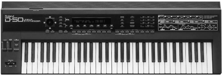
The D-50, released in 1987, was Roland's first fully digital synthesizer. Equipped with an LA (Linear Arithmetic Synthesis) format sound generator that combined PCM and subtractive synthesis, it opened the door to countless new sounds for levels of creativity surpassing anything up to that point. The D-50 is a renowned, historically significant synthesizer that Roland, the company that laid the foundation for digital synthesizers, is proud to have created.
The D-550, also released in 1987, shrank the D-50's powerful synthesizer engine into a mere two rack spaces.
Now, more than fifteen years after it came on the scene, the D-50 continues to be used by creative artists around the world. There are numerous sound libraries stocked with many original patches. In the course of time, however, keyboards and buttons age and wear out. It looked like the day would come when the D-50's sounds would no longer be heard.
In taking up the challenge of realizing new possibilities for the synthesizer, Roland has created a revolution in technology. At the same time, we want you to continue to using your treasured D-50 with peace of mind. Hence, the VC-1, which transforms your V-Synth/VariOS into a D-50, not only sweeps away any worries about your D-50 growing old, but also offers new potential that goes beyond the original instrument.
We hope that you will discover and enjoy the unrealized potential that the D-50 still offers. And if you have never played the D-50, you definitely need to check out its vintage sounds.
Try Out the Sounds. 15
Turning On the Power 15
Selecting Patches and Playing Sounds 16
Viewing Various Information 18
Applying Effects to the Sound. 19
Applying an Effect by Touching to the Pad. 19
Applying an Effect by Passing Over the D Beam 20
Assigning Parameters to the Controllers 21
How to Make the Patch Factors. 26
Settings Common to All Screens 26
CONTROL 28
OUTPUT (Output Mode) 29
CHASE 31
TONE TUNE 32
MIDI. 32
Saving Patches You've Created 33
Naming a Patch 33
Saving Patches 34
Reset to Default Factory Settings. 35
Transferring Patches To and From the D-50/550 36
Transferring Patches from the D-50 to the VC-1 36
Transfer the patch from the memory card to the D-50/550 37
Transferring Patches from the D-50/550 to the VC-1 38
Saving Transferred Patches with the VC-1 39
Transferring Patches from the VC-1 to the D-50/550....40
Copying a Reverb Type 42
Overview of the VC-1 44
Memory Structure 44
The Basic Concept of a Tone 45
Structure of Tone Parameters 48
Creating a Patch 50
How to Make the Patch Settings. 50
Useful Functions for Editing 51
Editing a Value. 51
Undoing an editing Operation 51
Editing with the Panel Controls (Partial Select) 52
Silencing the Sound of the Partial 52
Copying Tone Settings 53
Copying Parameter Settings. 54
Auditioning the Sound Before Editing 55
Initializing Patch Settings 56
Tone Parameters 57
Common Parameters 57
Structure 57
P-ENV (Pitch Envelope) 58
LFO (Low Frequency Oscillator) 60
EQ/CHORUS (Equalizer/Chorus) 61
Partial Parameters 63
Settings for the Entire VC-1.78
How to Make the System Function Settings. 78
Initializing the System Settings. 82
Connecting to Your Computer via USB 83
Recovering the System from the CD-ROM. 83
Selecting the V-Synth's USB Storage Mode 83
Connecting the V-Synth to Your Computer via USB 84
Recovering the System 86
Canceling the USB Connection 86
Exchanging MIDI Messages with Your Computer. 88
Panel Descriptions
When using the V-Synth with the VC-1, the actual functions of the V-Synth's buttons and knobs may not correspond to the functions ascribed to these controls on the V-Synth's panel. Here is a description of the names and functions in each section of the V-Synth when it is used with the VC-1. Please read this material together with "Panel Descriptions" in the V-Synth Owner's Manual. Controls whose functions do not match what is shown on the panel are indicated with a VC-1 mark.
Front Panel
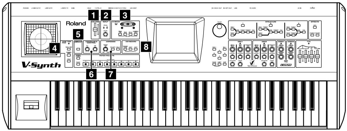
1 VOLUME slider
Adjusts the overall volume that is output from the rear panel MAIN OUT jacks and PHONES jack. (p. 15)
Not used with the VC-1. VC-1
3 D BEAM
You can apply a variety of effects to sounds simply by moving your hand.
- The Time Trip effect is not applied. VC-1
| Display | Function |
| Indicators (L, R) | If the D Beam controller is on, these will light when you move your hand over the controller. |
| [TIME TRIP] | Switches the D Beam controller on/off. The effect to be controlled can be selected by pressing the relevant button. (p. 20) |
| [TIME] |
| [PITCH] |
| [ASSIGNABLE] |
TIME TRIP PAD
By touching the pad surface with your finger you can apply a variety of effects to the sound.
- The Time Trip effect is not applied. VC-1
| Display | Function |
| Indicator | This will light when you touch the Time Trip Pad. |
| [TIME TRIP] | This switches the Time Trip Pad on and off. The effect being controlled switches according to the buttons pressed. (p. 19) |
| [ASSIGNABLE] |
| [HOLD] | Switches hold on/off for the effect controlled by the Time Trip pad. |
5 V-LINK
Not used with the VC-1. VC-1
6 ASSIGNABLE CONTROL
You can use them to modify the sound in realtime.
| Display | Function |
| [C1] | Adjusts the Aftertouch Sens (p. 79). VC-1 |
| [C2] | These can be assigned a variety of D-50 different functions, allowing you to change the tone in real time. (p. 22) |
7 ARPEGGIO
You can use them to modify the sound in realtime.
- The Arpeggiator is not available for use. VC-1
| Display | Function |
| [TEMPO] | Adjusts the Chase time (p. 31) or the Portamento time (p. 28). VC-1 |
| [ON/OFF] | Switches the Chase function on/off. VC-1 |
| [HOLD] | Switches the Portamento function on/off. VC-1 |
8 KEYBOARD
Here you can change the pitch range of the keyboard.
| Display | Function |
| [TRANSPOSE] | Modifies the pitch range of the keyboard in semitone steps (-12 – +12 semitones). Set the desired amount of transposition by holding down [TRANSPOSE] and pressing [+OCT] or [-OCT]. |
| [-OCT], [+OCT] | Pressing [+OCT] or [-OCT] transposes the pitch of the keyboard in 1 octave units (-3 – +3 octaves). |
- Changes you make the KEYBOARD settings are only temporary—they will be discarded as soon as the power is turned off. If you want you keep any changes you've made, you must save them in the VC-1. ("How to Make the System Function Settings" (p. 78))
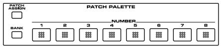
9 PATCH PALETTE
Here you can recall patches. Vc-1
| Display | Function |
| [NUMBER] (1-8) | These buttons let you select patches. VC-1 |
| [BANK] | You can change the Patch Palette bank by holding down this button and pressing [NUMBER] (1-8) |
| [PACKAGE] | Not used with the VC-1. VC-1 |
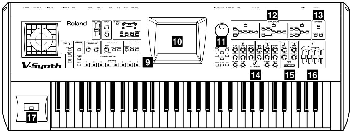
10 Display
This displays information regarding the operation you are performing.
- The explanations in this manual include illustrations that depict what should typically be shown by the display. Note, however, that your unit may incorporate a newer, enhanced version of the system (e.g., includes newer sounds), so what you actually see in the display may not always match what appears in the manual.
| Display | Function |
| VALUE Dial | This is used to modify values. If you hold down [SHIFT] as you turn the VALUE dial, the value will change in greater increments. |
| [DEC/-], [INC/+] | This is used to modify values. If you keep on holding down one button while pressing the other, the value change accelerates. If you press one of these buttons while holding down [SHIFT], the value will change in bigger increments. (p. 51) |
| [▲], [▼], [←], [▶] | Moves the cursor location up/down/left/right. (p. 51) |
| [MODE] | Opens the Mode Menu window. |
| [SHIFT] | This button is used in conjunction with other buttons to execute various functions. |
| [EXIT] | Return to the PATCH TOP screen, or close the currently open window. In some screens, this causes the currently executing function to be aborted. |
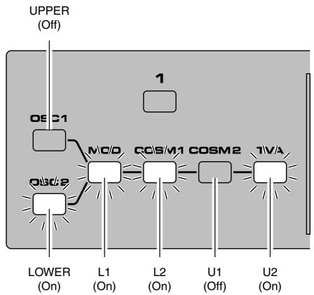
12 STRUCTURE
Switches the various functions on/off. VC-1
13 EFFECTS
Here you can switch the onboard effects (chorus and reverb) on/off. When an effect is on, the indicator for its button will light.
| Display | Function |
| [MFX] | Switches chorus of the UPPER tone on and off. VC-1 |
| [CHORUS] | Switches chorus of the LOWER tone on and off. VC-1 |
| [REVERB] | Switches reverb on and off. |
14 osc1, osc2
These can be assigned a variety of the D-50's different functions, allowing you to change the tone in real time. (p. 23) Vc-1
15 COSM1, COSM2
These can be assigned a variety of the D-50's different functions, allowing you to change the tone in real time. (p. 23) Vc-1
15 TVA
These can be assigned a variety of the D-50's different functions, allowing you to change the tone in real time. (p. 23) Vc-1
Pitch Bend/Modulation Lever
This allows you to control pitch bend or apply vibrato.
Rear Panel
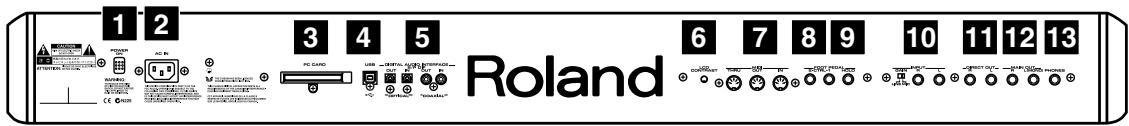
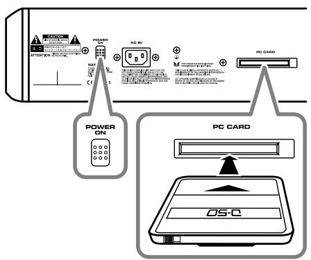
1 POWER Switch
Press to turn the power on/off. (p. 15)
2 AC Inlet
Connect the included power cord to this inlet.
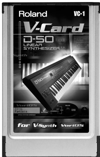
3 PC CARD Slot
The VC-1 can be inserted here.
- Carefully insert the PC card all the way in—until it is firmly in place.
- Never insert or pull out while the VC-1 (V-Synth) is turned on.
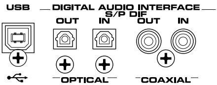
4 USB Connector
You can connect it to your personal computer to send or receive MIDI messages. (p. 83)
5 DIGITAL AUDIO INTERFACE Connector
These connectors input/output a digital audio signal (stereo; conforming to IEC60958). The output signal is identical to the signal that is output from the MAIN OUT jacks.
- IEC60958 is a digital interface format used for consumer digital audio devices.
6 LCD CONTRAST Knob
Adjusts the display contrast.
7 MIDI Connectors (IN, OUT, THRU)
These connectors can be connected to original D-50 (or other MIDI devices) to receive and transmit MIDI messages. (p. 83)
8 CTRL 1/2 PEDAL Jacks
You can connect optional expression pedals (EV-5, BOSS FS-5U, etc.) to these jacks.
| Display | Function |
| CTRL 1 PEDAL | Adjusts the volume. |
| CTRL 2 PEDAL | By assigning a desired function to a pedal, you can use it to select or modify sound. (p. 23) |
9 HOLD PEDAL Jack
An optional pedal switch (DP series, BOSS FS-5U, etc.) can be connected to this jack for use as a hold pedal.
Not used with the VC-1. VC-1
11 DIRECT OUT Jacks (L, R)
Not used with the VC-1. VC-1
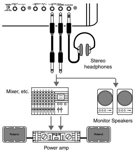
12 MAIN OUT Jacks (L (MONO), R)
These jacks output the audio signal to the connected mixer/amplifier system in stereo. For mono output, use the L jack. (p. 15)
13 PHONES Jack
This is the jack for connecting headphones (sold separately). (p. 15)
Turning On the Power
To prevent malfunction and/or damage to speakers or other devices, always turn down the volume, and turn off the power on all devices before making any connections.
- Before hooking anything up, make sure that the power on all of your gear is turned OFF.
- Connect the V-Synth to your amp/speaker system.
-
After correctly inserting the VC-1 into the PC card slot in the V-Synth's rear panel, switch ON the POWER switch.
-
Carefully insert the PC card all the way in—until it is firmly in place.
- This unit is equipped with a protection circuit. A brief interval (a few seconds) after power up is required before the unit will operate normally.
- Always make sure to have the volume level turned down before switching on power. Even with the volume all the way down, you may still hear some sound when the power is switched on, but this is normal, and does not indicate a malfunction.
- Never insert or pull out while the VC-1 (V-Synth) is turned on.
- Turn on the power for any connected amplifiers or speakers.
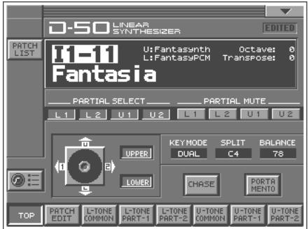
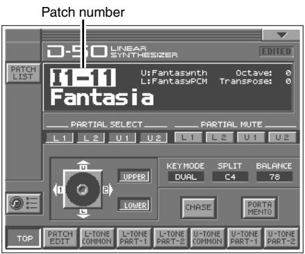
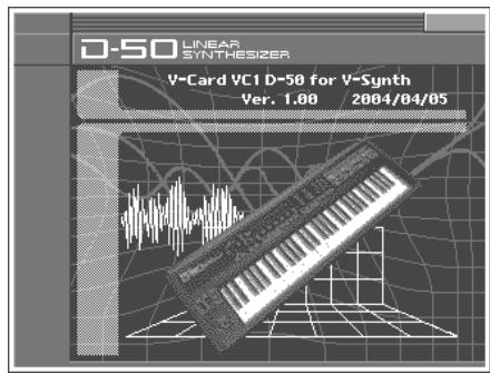
- Wait for the VC-1 to start up. When it has started up normally, a screen like the following will appear. The display shows the selected Patch.
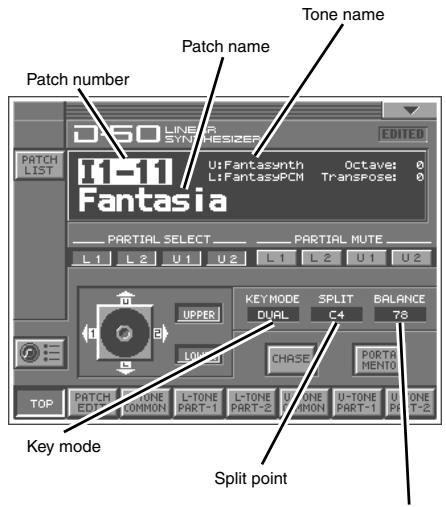
The volume balance of the Upper & Lower Tone
Selecting Patches and Playing Sounds
The VC-1 comes with a wide range of onboard sounds, including single tones called patches.
A Patch is represented by a Patch Bank (Pre1-6, Int1-8), a Bank (1-8) and a Number (1-8).
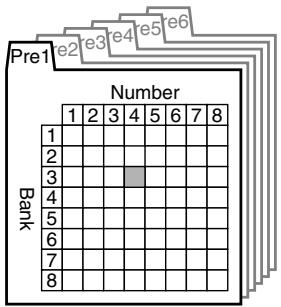
Patch bank (Pre1-6)

Patch No.: P1-34
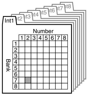
Patch bank (Int1-8)

Patch No.: I1-72
| Patch Banks | Included patches | Overwrite | Remarks |
| Pre1 | D-50 | No | Original D-50 preset patches |
| Pre2 | VC-1 | No | Newly added patches VC-1 |
| Pre3 | PN-D50-01 | No | D-50/D-550 sound library |
| Pre4 | PN-D50-02 | No | D-50/D-550 sound library |
| Pre5 | PN-D50-03 | No | D-50/D-550 sound library |
| Pre6 | PN-D50-04 | No | D-50/D-550 sound library |
| Int1 | same as Pre1 | Yes | - |
| Int2 | same as Pre2 | Yes | - |
| Int3 | same as Pre3 | Yes | - |
| Int4 | same as Pre4 | Yes | - |
| Int5 | same as Pre5 | Yes | - |
| Int6 | same as Pre6 | Yes | - |
| Int7 | (blank) | Yes | - |
| Int8 | (blank) | Yes | - |
There are three ways of patch selection.
- Selecting Patches with the VALUE dial.
- Selecting Patches from the list.
- Selecting Patches with Patch Palette.
Selecting Patches with the VALUE dial
- Make sure the PATCH TOP screen is displayed. If the PATCH TOP screen—shown right—is not displayed, press [EXIT] once or twice until the PATCH TOP screen appears.
- Play the keyboard to hear what the selected patch sounds like. To change to a different patch, touch the Patch number to highlight it, and then turn the VALUE dial or press [INC/+], [DEC/-]. At this time you can switch more rapidly by holding down [SHIFT] while you perform these operations.
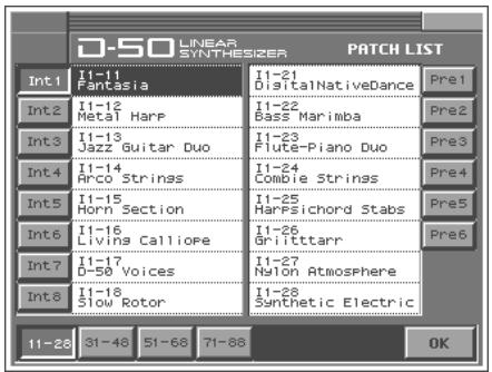
Selecting Patches from the List
You can easily find the desired patch by selecting it from the patch list.
- Make sure the PATCH TOP screen is displayed. If the PATCH TOP screen is not displayed, press [EXIT] once or twice until the PATCH TOP screen appears.
- Touch
in the upper left area of the display. The PATCH List window appears.
- Select a patch from the list. Either turn the VALUE dial or use [INC/+], [DEC/-] to select a patch. You can also select a patch by touching it on the display.
- To view higher-numbered patches, touch <31-48> -71-88>, located at bottom of the screen. To view other Patch banks, touch <Pre1>-Pre6> , <Int1>-Int8> , located at either side of the screen.
- Touch . The patch is selected and the PATCH LIST window closes.
Selecting Patches with Patch Palette
You can select patches of currently selected Patch Bank instantly by simply pressing NUMBER [1]-[8].
- Make sure the PATCH TOP screen is displayed.
- Press NUMBER [1]–[8] to select a patch. To switch between patch palette banks, hold down [BANK] and press NUMBER [1]–[8].
- In the upper right of the screen, touch < > . A pulldown menu appears.
- In the pulldown menu, touch . The Information window appears.
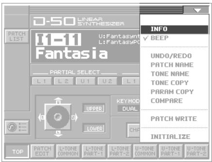
- This window shows the following information.
Ver.: The VC-1's program version
- When you have finished viewing the information, press [EXIT] to close the window.
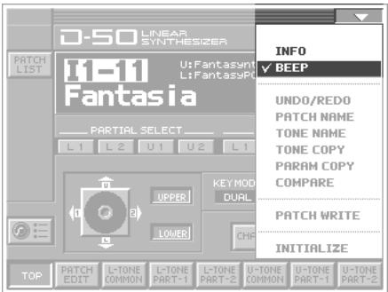
Enabling or Disabling the Beep Tone
You can specify whether or not a beep tone will be heard when you touch a valid point on the touch screen. At the factory setting, the beep tone will be sounded.
- In the upper right of the screen, touch < > . A pulldown menu appears.
- In the pulldown menu, touch to add a check mark (✔). With this setting, the beep tone will be heard. If you perform the same procedure once again, the check mark will be cleared and the beep tone will no longer be heard.
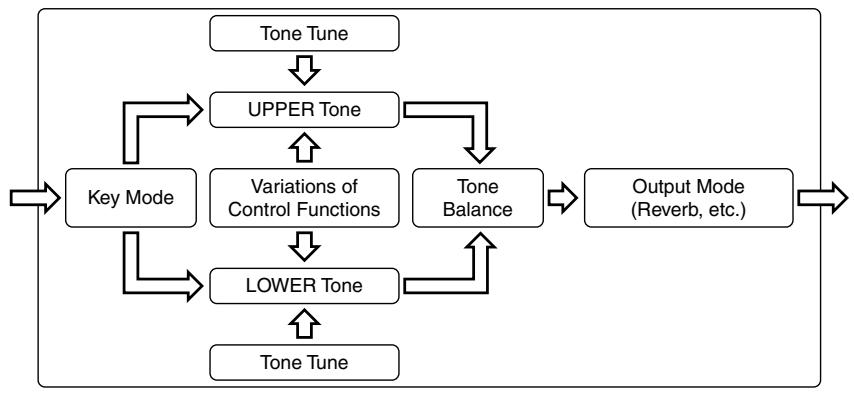
The performance controlling functions (we call them factors in this manual) in each Patch can be edited by taking the following procedure.
A patch consists of several Factors as show below.
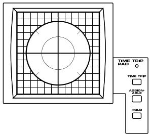
Applying an Effect by Touching to the Pad
You can apply a variety of effects by touching your fingertip to the Time Trip pad located at the left side of the V-Synth's front panel. The Time Trip Pad settings are saved with each patch. This means that you can create patches that contain Time Trip Pad settings you like.
- Access the PATCH TOP Screen.
- Choose the function that you want to control from the Time Trip pad, and press the TIME TRIP PAD button for that function.
| Button | Functions |
| [TIME TRIP] | This provides the same effect as the D-50's joystick (tone balance or partial balance). |
| [ASSIGNABLE] | Apply the effect that is specified by each patch. (CTRL Setup; p. 26) |
| [HOLD] | you can cause the effect to be held even after you take your finger off the Time Trip pad. |
- While you play the keyboard to produce sound, place your fingertip on the Time Trip pad and move your finger in the following way.
If [TIME TRIP] is on
Using the Time Trip Pad, the following two volume balance controls can be adjusted at the same time.
Volume balance of the two Partial sounds of either Tone; Upper or Lower.
Volume balance of the Upper and the Lower tones.
The tone for which the partial balance is to be controlled is selected using the Tone Select button. When you touch the Time Trip pad, the volume balance changes as shown below. Changing the partial balance creates huge changes in the tone, providing very distinctive effects.
![ROLAND VC-1 - If [TIME TRIP] is on - 1](/content/2025/01/130928/images/1b81b0d0788000219d23da6b1e7064e438465529fe45b6f01a77eb0847b113cd.jpg)
Tone Select button (On:pressed)
![ROLAND VC-1 - If [TIME TRIP] is on - 2](/content/2025/01/130928/images/f2b58161fd4ebf1610316d4399c347096947c094e45f997bcde647aa74f25c92.jpg)
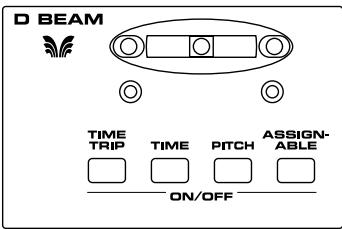
Applying an Effect by Passing Over the D Beam
The D Beam controller can be used simply by waving your hand over it. It can be used to apply various effects, depending on the function that is assigned to it. You can also create effects in which the sound changes instantaneously, in a way that would not be possible by operating a knob or the bender lever. The D Beam controller settings are saved with each patch. This means that you can create patches that contain D Beam settings you like.
- Access the PATCH TOP Screen
- Choose the function that you want to control from the D Beam controller, and press the D BEAM button for that function to turn on the D Beam controller.
| Buttons | Functions |
| [TIME TRIP] | This provides the same effect as that when, after the key is played, it is then pressed with even greater force. (Aftertouch) |
| [TIME] | This provides the same effect as that achieved by tilting the modulation level away from you. (Modulation) |
| [PITCH] | This provides the same effect as that achieved by tilting the pitch bend level to the left and right. (Pitch Bend) |
| [ASSIGNABLE] | Apply the effect that is specified by each patch. (“How to Make the Patch Factors” (p. 26)) |
- While playing the keyboard to produce sound, place your hand over the D Beam, and slowly move it up and down.
- To turn off the D Beam controller, once again press the button that you pressed in step 2, so its indicator goes out.
Assigning Parameters to the Controllers
You can assign a variety of patch factors (p. 133), tone parameters (p. 134), and other settings to the V-Synth's complement of controller sections, such as the Time Trip pad, the D Beam Controller, and the OSC1/OSC2 sections. This is referred to as the Control Setup. With intuitive editing of sound sources with the knobs and sliders and greater performance expression with the Time Trip Pad, you can use the D-50 in ways that go way beyond the original instrument.
| Controllers | Parameters |
| TIME TRIP PAD, D BEAM, C2 Knob | MIDI Control Change Message |
| OSC1, OSC2, COSM1, COSM2, TVA | Patch Factor (p. 133)
Tone Parameters (p. 134)
Partial Parameters (p. 135) |
- Access the PATCH TOP Screen.
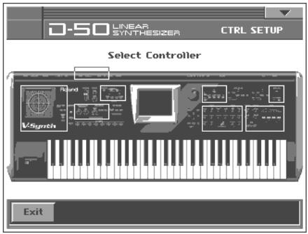
- Touch in the lower left of the screen. The CTRL SETUP window appears.
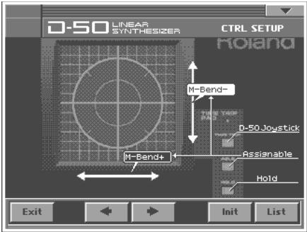
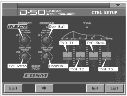
- Touch the Time Trip pad, D-Beam Controller, or other controller to which you want to assign the parameter. The display of that controller section expands in the screen. The screen features at this time function as follows.
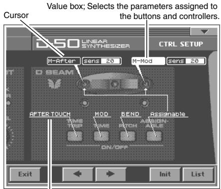
Underline; Shows the button and controller functions.
- When editing a parameter that requires you to specify a value, move the cursor to the value box of that parameter. Then modify the value by either turning the VALUE dial or pressing [INC/+] or [DEC-]. Parameters marked by CTRL can be controlled by specific CTRL Setup. For details on each parameter, refer to the corresponding reference page. The on-screen keys have the following functions.
| Keys | Functions |
| ←, → | Switches the set of controllers to be enlarged in the display. |
| List | Displays the parameters to be assigned as a list. |
| Exit | Returns to the CTRL SET screen. |
| Init | Restores the assigned parameters to their original factory condition. |

- When you have finished CTRL Setup, touch <OK> to close the CTRL Setup window.
TIME TRIP PAD
ASSIGNABLE X table 1 (p.22)
ASSIGNABLE Y table 1 (p.22)
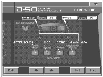
D BEAM
ASSIGNABLE L table 1 (p.22)
ASSIGNABLE R table 1 (p.22)
Sens L 0 - 20
Sens R 0 - 20
C2
C2 table 1 (p. 22)
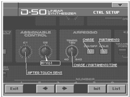
table 1
You can control the following parameters.
| Display | Parameters |
| Assignable | Parameter - MIDI (p. 140) |
| M-Mod | MIDI Modulation |
| M-Vol | MIDI Volume |
| M-Hold | MIDI HOLD |
| M-After | MIDI Aftertouch |
| M-Bend+ | MIDI Pitch Bend + |
| M-Bend- | MIDI Pitch Bend - |
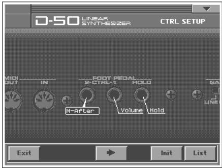
PEDAL2
PEDAL2 Off, ToneBal, M-After, M-Mod
| Display | Functions |
| Off | The VC-1 is NOT Controlled. |
| ToneBal (Tone Balance) | Controls the volume balance of the Upper and the Lower Tones. |
| M-After (Aftertouch) | Controls the Aftertouch effect. |
| M-Mod (Modulation) | Controls the vibrato effect. |
OSC1, OSC2
OSC1 PITCH table 2 (p. 25)
OSC1 TIME table 2 (p. 25)
OSC1 FORMAL table 2 (p. 25)
OSC1 LFO DP1 table 2 (p. 25)
OSC1 LFO DP2 table 2 (p. 25)
OSC1 LFO DP3 table 2 (p. 25)
OSC1 LFO RATE table 2 (p. 25)
OSC1 LEVEL table 2 (p. 25)
OSC2 PITCH table 2 (p. 25)
OSC2 TIME table 2 (p. 25)
OSC2 FORMAL table 2 (p. 25)
OSC2 LFO DP1 table 2 (p. 25)
OSC2 LFO DP2 table 2 (p. 25)
OSC2 LFO DP3 table 2 (p. 25)
OSC2 LFO RATE table 2 (p. 25)
OSC2 LEVEL table 2 (p. 25)
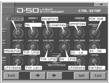
COSM1, COSM2
COSM1WIDTH table2(p.25)
COSM1 DETUNE table 2 (p. 25)
COSM2WIDTH table 2 (p.25)
COSM2 DETUNE table 2 (p. 25)
TVA Attack table 2 (p. 25)
TVA Decay table 2 (p. 25)
TVA Sustain table 2 (p. 25)
TVA Release table 2 (p. 25)
LIST (OSC1, OSC2, COSM1, COSM2 and TVA)
- Tone Parameters; The Tones (UPPER or LOWER) to be applied are specified with the Tone Select button.
- Partial Parameters; The Partials (L1, L2, L3 or L4) to be applied are specified with the Partial Select button.
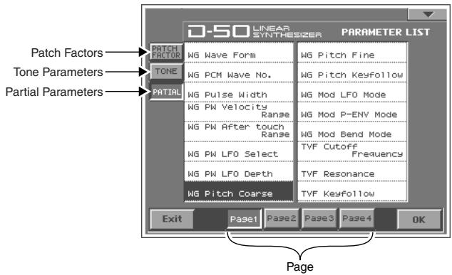
Specify the Tones or the Partials to be applied
The partials to which the tone parameters assigned to the different knobs and sliders (OSC1, OSC2, COSM1, COSM2 and TVA) are applied are specified with the Tone Select button or the Partial Select button.
- Tone Parameters; The Tones (UPPER or LOWER) to be applied are specified with the Tone Select button.
- Partial Parameters; The Partials (L1, L2, L3 or L4) to be applied are specified with the Partial Select button.
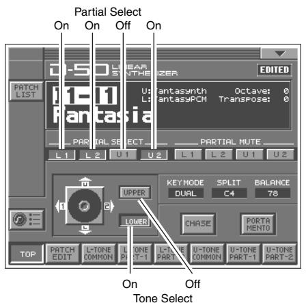
* The Tone Select or the Partial Select setting will be written by the Patch Write Procedure.
You can control the following parameters.
table 2
| Display | Parameters |
| PATCH TOP (p. 26) |
| ToneBal | Tone Balance |
| PATCH EDIT CONTROL (p. 28) |
| BendRang | Bender Range |
| AftrPB | Aftertouch Bend Range |
| PortTime | Portamento Time |
| PortMode | Portamento Mode |
| PATCH EDIT OUTPUT (p. 29) |
| Rev Bal | Reverb Balance |
| TotalVol | Total Volume |
| PATCH EDIT CHASE (p. 31) |
| ChasLevel | Chase Level |
| ChasTime | Chase Time |
| PATCH EDIT TONE TUNE (p. 32) |
| LowerKey | Lower Tone Key Shift |
| UpperKey | Upper Tone Key Shift |
| LowerTun | Lower Tone Fine Tune |
| UpperTun | Upper Tone Fine Tune |
| TONE COMMON STRUCT (p. 57) |
| PartBal | Partial Balance |
| TONE COMMON P-ENV (p. 58) |
| PEnvVelo | P-ENV Velocity Range |
| PEnvTKF | P-ENV Time Keyfollow |
| PEnvT1 | P-ENV Time 1 |
| PEnvT2 | P-ENV Time 2 |
| PEnvT3 | P-ENV Time 3 |
| PEnvT4 | P-ENV Time 4 |
| PEnvL0 | P-ENV Level 0 |
| PEnvL1 | P-ENV Level 1 |
| PEnvL2 | P-ENV Level 2 |
| PEnvSusL | P-ENV Sustain Level |
| PEnvEndL | P-ENV End Level |
| PModLFOD | P-Mod LFO Depth |
| PModLevr | P-Mod Lever |
| PModAfr | P-Mod Aftertouch |
| TONE COMMON LFO (p. 60) |
| LFO1Wave | LFO-1 Waveform |
| LFO1Rate | LFO-1 Rate |
| LFO1Dely | LFO-1 Delay Time |
| LFO1Sync | LFO-1 Sync |
| LFO2Wave | LFO-2 Waveform |
| LFO2Rate | LFO-2 Rate |
| LFO2Dely | LFO-2 Delay Time |
| LFO2Sync | LFO-2 Sync |
| LFO3Wave | LFO-3 Waveform |
| LFO3Rate | LFO-3 Rate |
| Display | Parameters |
| LFO3Dely | LFO-3 Delay Time |
| LFO3Sync | LFO-3 Sync |
| TONE COMMON EQ/CHORUS (p. 61) |
| EQ Lg | Low EQ Gain |
| EQ Hg | High EQ Gain |
| ChorRate | Chorus Rate |
| ChorDepth | Chorus Depth |
| ChorBal | Chorus Balance |
| TONE PARTIAL FORM (p. 64) |
| Waveform | WG Waveform |
| PCM No# | WG PCM Wave No. |
| PW | WG Pulse Width |
| PW Velo | WG PW Velocity Range |
| PW Aattr | WG PW Aftertouch Range |
| PW LFO | WG PW LFO Select |
| PW LFOD | WG PW LFO Depth |
| TONE PARTIAL PITCH (p. 66) |
| PichCors | WG Pitch Coarse |
| PichFine | WG Pitch Fine |
| PichKF | WG Pitch Keyfollow |
| PichLFO | WG Mod LFO Mode |
| PichENV | WG Mod P-ENV Mode |
| PichBend | WG Mod Bend Mode |
| TONE PARTIAL TVF (p. 68) |
| TVF Freq | TVF Cutoff Frequency |
| TVF Reso | TVF Resonance |
| TVF KF | TVF Keyfollow |
| TVF BP | TVF Bias Point/Dir |
| TVF Blvl | TVF Bias Level |
| TVFDpth | TVF ENV Depth |
| TVFVelo | TVF ENV Velocity Range |
| TVF DKF | TVF ENV Depth Keyfollow |
| TVF TKF | TVF ENV Time Keyfollow |
| TVF T1 | TVF ENV Time 1 |
| TVF T2 | TVF ENV Time 2 |
| TVF T3 | TVF ENV Time 3 |
| TVF T4 | TVF ENV Time 4 |
| TVF T5 | TVF ENV Time 5 |
| TVF L1 | TVF ENV Level 1 |
| TVF L2 | TVF ENV Level 2 |
| TVF L3 | TVF ENV Level 3 |
| TVF SusL | TVF ENV Sustain Level |
| TVF EndL | TVF ENV End Level |
| Display | Parameters |
| TONE PARTIAL | TVA (p. 73) |
| TVA Levl | TVA Level |
| TVA Velo | TVA Velocity Range |
| TVA BP | TVA Bias Point/Dir |
| TVA Blvl | TVA Bias Level |
| TVA Velo | TVA ENV Velocity Folw |
| TVA TKF | TVA ENV Time Keyfollow |
| TVA T1 | TVA ENV Time 1 |
| TVA T2 | TVA ENV Time 2 |
| TVA T3 | TVA ENV Time 3 |
| TVA T4 | TVA ENV Time 4 |
| TVA T5 | TVA ENV Time 5 |
| TVA L1 | TVA ENV Level 1 |
| TVA L2 | TVA ENV Level 2 |
| TVA L3 | TVA ENV Level 3 |
| TVA SusL | TVA ENV Sustain Level |
| TVA EndL | TVA ENV End Level |
| TONE PARTIAL MOD (p. 76) |
| TVF LFO | TVF Mod LFO Select |
| TVF LFOD | TVF Mod LFO Depth |
| TVF Aftr | TVF Mod Aftertouch Range |
| TVA LFO | TVA Mod LFO Select |
| TVA LFOD | TVA Mod LFO Depth |
| TVA Aftr | TVA Mod Aftertouch Range |
How to Make the Patch Factors
The Display shows several Factors at a time. If necessary, Scroll up or down the Display to find the Factor to be edited. (Patch Parameters; p. 26)
- Access the PATCH TOP Screen.
- Touch at the bottom of the screen.
- Touch one of the tabs in the left of the screen to select the desired editing screen.
: Control Edit, Portamento Edit (p. 28)