
TE 40-AVR - Drill HILTI - Free user manual and instructions
Find the device manual for free TE 40-AVR HILTI in PDF.


| Product Type | Rotary Hammer Drill (Combination Hammer) |
| Model | TE 40-AVR |
| Brand | Hilti |
| Rated Power Input | 1,100 W |
| Impact Energy (per EPTA 05/2009) | 5.6 J |
| Weight (according to EPTA 01/2003) | 5.6 kg |
| Dimensions (L x H x W) | 425 x 220 x 95 mm |
| Drilling Dia. in Concrete (Hammer) | 12 - 40 mm |
| Drilling Dia. in Concrete (Hammer with Hollow Drill Bit) | 40 - 80 mm |
| Drilling Dia. in Steel | Up to 13 mm |
| Drilling Dia. in Wood | Up to 32 mm |
| Chuck System | TE-C (SDS Plus) |
| No-Load Speed (Rotary Only) | 0 - 1,200 rpm |
| Impact Rate at Rated Speed | 3,900 impacts/min |
| Active Vibration Reduction (AVR) | Yes |
| Service Indicator | LED for carbon brush replacement |
| Power Supply | Corded electric (120 V or 230 V depending on region) |
| Cable Length | 4 m |
| Safety Features | Slip clutch, AVR system, electric safety (grounding) |
| Maintenance & Cleaning | Regular cleaning of air vents, check carbon brushes, use Hilti grease for chuck |
| Spare Parts and Repairability | Available through Hilti service centers; brush caps for easy replacement |
| General Information | Designed for professional heavy-duty drilling and chiseling; complies with relevant EPTA and IEC standards |
Frequently Asked Questions - TE 40-AVR HILTI
User questions about TE 40-AVR HILTI
0 question about this device. Answer the ones you know or ask your own.
Ask a new question about this device
Download the instructions for your Drill in PDF format for free! Find your manual TE 40-AVR - HILTI and take your electronic device back in hand. On this page are published all the documents necessary for the use of your device. TE 40-AVR by HILTI.
USER MANUAL TE 40-AVR HILTI
natural_image
Red TE 40-AVR drill put tool against red background (no visible text or symbols on the device body)1
2

3
4

5
6

7

8

9



TE 40 / TE 40-AVR Kombihammer
Head of BA Quality and Process Management
Business Area Electric Tools & Acces-
sories
01/2012
Jan Doongaji
Executive Vice President
Business Unit Power
Tools & Accessories
01/2012
It is essential that the operating instruct are read before the power tool is open the first time.
Always keep these operating instructions gether with the power tool.
Ensure that the operating instructions a with the power tool when it is given persons.
Contents Page
| 1 | General information 14 | |
| 2 | Description 15 | |
| 3 | Insert tools, accessories 17 | |
| 4 | Technical data 17 | |
| 5 | Safety instructions 19 | |
| 6 | Before use 21 | |
| 7 | Operation | 21 |
| 8 | Care and maintenance | |
| 9 | Troubleshooting | 24 |
| 10 | Disposal | 25 |
| 11 | Manufacturer's warranty - tools | |
| 12 | EC declaration of conformity (original) |
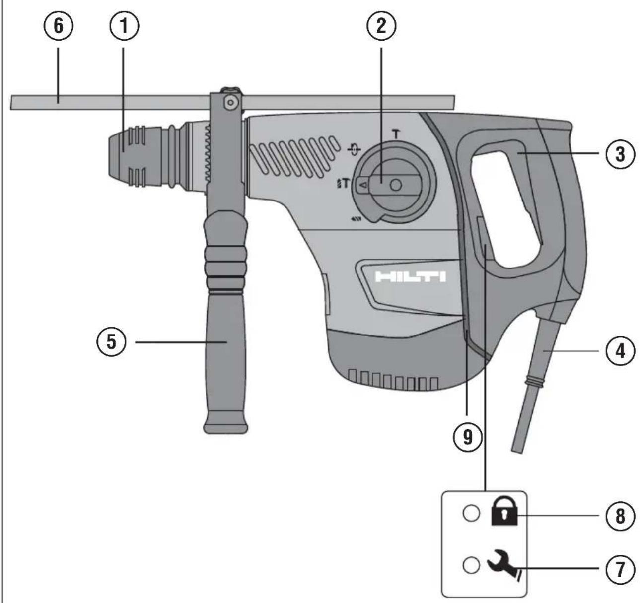
These numbers refer to the corresponding illustrations. The illustrations can be found on the fold-out cover pages. Keep these pages open while studying the operating instructions. In these operating instructions, the designation “the power tool” always refers to the TE 40 or TE 40-A combihammer.
re to operating controls and indicators 1
① Chuck
② Function selector switch
③ Control switch
④ Supply cord
⑤ Side handle
⑥ Depth gauge
⑦ Service indicator
⑧ Theft protection indicator (optional)
⑨ AVR active vibration reduction (only TE 40-AVR)
23
25
26
1 General information
1.1 Safety notices and their meaning
DANGER
Draws attention to imminent danger that will lead to serious bodily injury or fatality.
WARNING
Draws attention to a potentially dangerous situat could lead to serious personal injury or fatality.
CAUTION
Draws attention to a potentially dangerous situation that could lead to slight personal injury or damage to the equipment or other property.
NOTE
Draws attention to an instruction or other useful information.
1.2 Explanation of the pictograms and other information
Warning signs
General warning

Warning: electricity

Warning: hot surface
Obligation signs

Wear eye protection

Wear a hard hat

Wear ear protection

Wear
protective
gloves

Wear
breathing
protection
Symbols

Read the operating instructions before use

Returning materials for recycling

Drilling
without
hammering

Hammer drilling

Chiseling

Chisel
position
adjustment

Volts Amps


Watts
Alternating
current
Hertz
Rated
speed
under no load

Revolutions per minute

Diameter

Double insulated

Equipped with theft protection system

Lock symbol
Location of identification data on the power tool The type designation can be found on the type ide tion plate and the serial number on the side of th housing. Make a note of this data in your operating structions and always refer to it when making an er to your Hilti representative or service department.
Type:
Serial no.:
2 Description
2.1 Use of the product as directed
The power tool is an electrically-powered combihammer with pneumatic hammering mechanism.
The power tool is intended for drilling in concrete, masonry, metal and wood.
The power tool can also be used for light to medium-duty chiseling work on masonry and for surface finishing on concrete.
Working on materials hazardous to the health (e.g. asbestos) is not permissible.
The power tool is designed for professional use and may be operated, serviced and maintained only by trained, authorized personnel. This personnel must be informed of any special hazards that may be encountered. The power tool and its ancillary equipment may present hazards when used incorrectly by untrained personnel or when used not as directed.
The working environment may be as follows: construction site, workshop, renovation, conversion or new construction. The power tool may be used only in a dry environment.
Do not use the power tool where there is a risk of fire or explosion.
The power tool may be operated only when connected to a power supply providing a voltage and frequency in compliance with the information given on its type identification plate.
Modification of the power tool or tampering with its parts is not permissible.
To avoid the risk of injury, use only genuine Hilti accessories and insert tools.
Observe the information printed in the operating instructions concerning operation, care and maintenance.
2.2 Chuck
TE-C (SDS-plus) quick-change chuck
TE-T (SDS-top) quick-change chuck
2.3 Switches
Speed control switch for smooth starting Function selector switch: Hammer drilling Drilling without hammering Chiseling Chisel position adjustment (12 positions)
2.4 Grips
Vibration-absorbing, pivotable side handle Vibration-absorbing grip
2.5 Protective device
Mechanical safety clutch Electronic restart interlock to prevent the power tool starting unintentionally after an interruption in the electric supply (see section 9 “Troubleshooting”).
2.6 Lubrication
Oil lubrication
2.7 Active vibration reduction (only TE 40-AVR)
The power tool is equipped with an AVR active vibration reduction system which reduces vibration sign compared to power tools without active vibration reduction.
2.8 TPS theft protection system (optional)
The power tool may be equipped with the TPS theft protection system as an option. If the power tool is equipped with this feature, it can be unlocked and made ready for operation only through use of the corresponding TPS key.
2.9 LED indicators
Service indicator LED (see section "Care and maintenance") Theft protection system indicator (optional) (see section "Operation")
2.10 Items supplied as standard
1 Power tool with side handle
1 C h u c k
1 Hilti toolbox
1 Operating instructions
1 D e p t h g a u g e
1 Cleaning cloth
1 Grease
2.11 Using extension cords
Use only extension cords of a type approved for the application and with conductors of adequate cross-power tool may otherwise loose performance and the extension cord may overheat. Check the extension cord for damage at regular intervals. Replace damaged extension cords.
Recommended minimum conductor cross section and max. cable lengths
| Conductor cross section | 1.5 mm ^2 2 mm ^2 | 2.5 mm ^2 3.5 | mm ^2 | |
| Mains voltage 100V 30 m 50 m | ||||
| Mains voltage 110-120 V 20 m | 30 m | 40 m | ||
| Mains voltage 220-240 V 30 m | 75 m |
Do not use extension cords with 1.25 mm ^4 conductor cross section.
2.12 Using extension cords outdoors
When working outdoors, use only extension cords that are approved and correspondingly marked for this application.
2.13 Using a generator or transformer
This power tool may be powered by a generator or transformer when the following conditions are fulfilled: The unit must provide a power output in watts of at least twice the value printed on the type identification plate on the power tool. The operating voltage must remain within +5% and -15% of the rated voltage at all times, frequency must be in the 50 – 60 Hz range and never above 65 Hz, and the unit must be equipped with automatic voltage regulation and starting boost.
Never operate other power tools or appliances from the generator or transformer at the same time. Switching other power tools or appliances on and off may cause undervoltage and / or overvoltage peaks, resulting in damage to the power tool.
3 Insert tools, accessories
| Designation | Short designation | Item number, description |
| TPS Theft Protection System with Company Card, Company Remote and TPS-K key | 206999, optional | |
| Chuck TE-C 305590 | ||
| Chuck TE-T 285852 | ||
| Setting tool Setting tool with TE-C or TE-T con- | nection end | |
| Quick-release chuck Keyless chuck for wood and metal | drill bits with smooth or hex. shank, Chuck holder | |
| Dust removal system TE DRS-S |
| Designation | Short designation | Description |
| Hammer drill bits TE-C 5...28 mm | ||
| Hammer drill bits TE-T 6...32 mm | ||
| Breach bits TE-C 30...32 mm | ||
| Breach bits TE-T 32 mm | ||
| Percussion core bits TE-C 25...90 mm | ||
| Percussion core bits TE-T 50...90 mm | ||
| Chisels Pointed, flat and shaped chisels with | TE-C or TE-T connection ends | |
| Wood drill bits | 6...32 mm | |
| Metal drill bits | 6...13 mm |
4 Technical data
Right of technical changes reserved.
NOTE
The power tool is available in various voltage ratings. Please refer to the type identification plate for details of the power tool's voltage and power rating.
| Power tool | TE 40 / TE 40-AVR |
| Rated power input | 1,010 W |
| Power tool TE 40 / TE 40-AVR | |
| Rated voltage / rated current Rated voltage 100 V: 12.7 A | |
| Mains frequency 50...60 Hz | |
| Weight in accordance with EPTA procedure 01/25.63 kgTE 40 | |
| Weight in accordance with EPTA procedure 01/25.63 kgTE 40-AVR | |
| Dimensions (L x W x H) 425 mm x 113 mm x 243 mm | |
| Speed under no load 550/min | |
| Single impact energy in accordance with EPTA procedure 05/2009 | proced- |
| Drilling dia. range in concrete/masonry (hammer drilling) | 5...32 mm |
| Breach bits 30...32 mm | |
| Percussion core bits 50...90 mm | |
| Drilling dia. range in wood (solid) 6...32 mm | |
| Drilling dia. range in metal (solid) 6...13 mm | |
NOTE
The vibration emission level given in this information sheet has been measured in accordance with a standardised test given in EN 60745 and maybe used to compare on tool with another. It may be used for of exposure. The declared vibration emission level represents the main applications of the tool. However if the tool is used for different applications, with different accessories or poorly maintained, the vibration emission may differ. This may significantly increase the exposure level over the total working period. An estimation of the level vibration should also take into account the times when the tool is switched off or when it is running but not actually doing the job. This may significantly reduce the exposure level over the total working period. Identify additional safety measures to protect the operator from the effects of vibration such as: maintain the tool and the accessories, keep the hands warm, organisation of work patterns.
Noise and vibration information (measured in accordance with EN 60745-1):
| Typical A-weighted sound power level, TE 40-AVR | 105 dB (A) | ||||||||
| Typical A-weighted sound power level, TE 40-AVR | 104 dB (A) | ||||||||
| Typical A-weighted emission sound pressure level,94TEdB (A) | |||||||||
| Typical A-weighted emission sound pressure level,93TEdB (A) | |||||||||
| 40-AVR | |||||||||
| Uncertainty for the given sound level | 3 dB (A) | ||||||||
| Triaxial vibration value for the TE 40-AVR (vibrational measured in accordance with EN 60745-2-1 prAA:tor sum) | |||||||||
| Drilling in metal, _H,D (a) | < 2.5 m/s ^2 | ||||||||
| Triaxial vibration value for the TE 40-AVR (vibrational measured in accordance with EN 60745-2-6 prAB:tor sum) | |||||||||
| Hammer drilling in concrete, _H,D (a) | 10.7 m/s ^2 | ||||||||
| Chiseling, _H,Cheq | 9.9 m/s ^2 | ||||||||
| Triaxial vibration value for the TE 40 (vibration measured in accordance with EN 60745-2-1 prAA:sum) | |||||||||
| Drilling in metal, _H,D (a) | < 2.5 m/s ^2 | ||||||||
| Triaxial vibration value for the TE 40 (vibration measured in accordance with EN 60745-2-6 prAB:sum) | |||||||||
| Hammer drilling in concrete, _H (a) | 1 | 6 | . |
| Chiseling, (a_Cheq) | 1 | 6 | |
| Uncertainty (K) for triaxial vibration value 1.5 m/s ^2 | |||
Other information about the power tool
| Chuck TE-C (SDS-plus) |
| Chuck TE-T (SDS-top) |
| Protection class as per EN Protection class II (double insulated) as per EN 60745-1 |
en
5 Safety instructions
5.1 General Power Tool Safety Warnings
a)

WARNING
Read all safety warnings and all instruction to follow the warnings and instructions in electric shock, fire and/or serious injury. warnings and instructions for future referer The term “power tool” in the warnings refers to your mains-operated (corded) power tool or operated (cordless) power tool.
5.1.1 Work area safety
a) Keep work area clean and well lit. Cluttered or dark areas invite accidents.
b) Do not operate power tools in explosive spheres, such as in the presence of flam liquids, gases or dust. Power tools create which may ignite the dust or fumes.
c) Keep children and bystanders away while ing a power tool. Distractions can cause y control.
5.1.2 Electrical safety
a) Power tool plugs must match the outlet. modify the plug in any way. Do not use apter plugs with earthed (grounded) power. Unmodified plugs and matching outlets will risk of electric shock.
b) Avoid body contact with earthed or grounded surfaces, such as pipes, radiators, ranges refrigerators. There is an increased risk of shock if your body is earthed or grounded.
c) Do not expose power tools to rain or water tions. Water entering a power tool will increase risk of electric shock.
d) Do not abuse the cord. Never use the cord carrying, pulling or unplugging the power to Keep cord away from heat, oil, sharp ed, moving parts. Damaged or entangled cords increase the risk of electric shock.
e) When operating a power tool outdoors, use extension cord suitable for outdoor use. Use a cord suitable for outdoor use reduces the electric shock.
f) If operating a power tool in a damp loc unavoidable, use a residual current device
protected supply. Use of an RCD reduces the risk of electric shock.
5.1.3 Personal safety
may Staul alert, watch what you are doing and use Save calhmon sense when operating a power tool. I ce. not use a power tool while you are tired or the influence of drugs, alcohol or medication. A battery moment of inattention while operating power tools may result in serious personal injury.
b) Use personal protective equipment. Always wear eye protection. Protective equipment such as dust mask, non-skid safety shoes, hard hat, or hearing protection used for appropriate conditions will reduce personal injuries.
c) Prevent unintentional starting. Ensure the switch is in the off-position before connecting to power source and/or battery pack, picking up or carrying the tool. Carrying power tools with your finger o switch or energising power tools that have the s ou to lose on invites accidents.
d) Remove any adjusting key or wrench before tu ing the power tool on. A wrench or a key left tached to a rotating part of the power tool may Never in personal injury.
e) Do not overreach. Keep proper footing and balance at all times. This enables better control of power tool in unexpected situations.
f) Dress properly. Do not wear loose clothing or jewellery. Keep your hair, clothing and gloves away from moving parts. Loose clothes, jewellery or long hair can be caught in moving parts.
g) If devices are provided for the connection of a net condi- extraction and collection facilities, ensure these se the are connected and properly used. Use of dust collection can reduce dust-related hazards.
ord for
5.1.4 Power tool use and care
a) Do not force the power tool. Use the correct power tool for your application. The correct power tool will do the job better and safer at the rate which it was designed.
b) Do not use the power tool if the switch does risk of turn it on and off. Any power tool that cannot controlled with the switch is dangerous and must be repaired. (RCD)
c) Disconnect the plug from the power source and/or the battery pack from the power before making any adjustments, changing accessories, or storing power tools. Such preventive safety measures reduce the risk of starting the power tool accidentally.
d) Store idle power tools out of the reach dren and do not allow persons unfamiliar power tool or these instructions to operate power tool. Power tools are dangerous in of untrained users.
e) Maintain power tools. Check for misalignm binding of moving parts, breakage of part any other condition that may affect the power tool's operation. If damaged, have the pov repaired before use. Many accidents are ca poorly maintained power tools.
f) Keep cutting tools sharp and clean. Properly maintained cutting tools with sharp cutting edges likely to bind and are easier to control.
g) Use the power tool, accessories and tool bits etc. in accordance with these instructions, taking account the working conditions and the work to be performed. Use of the power tool for operations different from those intended could result in a hazardous situation.
5.1.5 Service
a) Have your power tool serviced by a qualified repair person using only identical replacement parts. This will ensure that the safety of the power tool is maintained.
5.2 Hammer safety warnings
a) Wear ear protectors. Exposure to noise can cause hearing loss.
b) Use auxiliary handles, if supplied with the Loss of control can cause personal injury.
c) Hold power tool by insulated gripping sun when performing an operation where the cutting accessory may contact hidden wiring or its own cord. Cutting accessory contacting a "live" w make exposed metal parts of the power tool and could give the operator an electric sho
5.3 Additional safety instructions
5.3.1 Personal safety
a) Always hold the power tool securely with hands on the grips provided. Keep the grips dry, clean and free from oil and grease.
b) Breathing protection must be worn if the power tool is used without a dust removal system work that creates dust.
c) Improve the blood circulation in your finger relaxing your hands and exercising your fi during breaks between working.
d) Avoid touching rotating parts. Switch the power tool on only after bringing it into position at the workpiece. Touching rotating parts, especially rotating insert tools, may lead to injury.
ce) Always lead the supply cord and extension cord tool away from the power tool to the rear while v ing. This helps to avoid tripping over the cord while working.
f) Children must be instructed not to play with the power tool.
of) cFile power tool is not intended for use by children, with bytlebilitated persons or those who have received the no instruction or training.
the hands
5.3.2 Power tool use and care
ent) Secure the workpiece. Use clamps or a vice to secure the workpiece. The workpiece is thus held more securely than by hand and both hands remain over tool free to operate the power tool.
b) Check that the insert tools used are compatible with the chuck system and that they are secu in the chuck correctly.
reC) less Always work from a secure, safe stance.
5.3.3 Electrical safety
a) Before beginning work, check the working area (e.g. using a metal detector) to ensure that no concealed electric cables or gas and water pip are present. External metal parts of the power tool may become live, for example, when an electric cable is damaged accidentally. This presents a serious risk of electric shock.
b) Check the power tool's supply cord at regular intervals and have it replaced by a qualified specialist if found to be damaged. If the machine supply cord is damaged it must be replaced with a specially-prepared and approved supply cord available from Hilti Customer Service. Check extension cords at regular intervals and replace them if found to be damaged. Do not touch the supply cord or extension cord if it is damaged while working. Disconnect the mains plug from the power outlet. Damaged supply cords or extension cords present a risk of electric shock.
c) Dirty or dusty power tools which have been used frequently for work on conductive materials may should be checked at regular intervals at a Hilti Service Center. Under unfavorable circumstances, dampness or dust adhering to the surface of the power tool, especially dust from conductive materials, may present a risk of electric shock.
d) When working outdoors with an electric tool both check to ensure that the tool is connected to electric supply by way of a ground fault circuit interrupter (RCD) with a rating of max. 30 mA (tripping current). Use of a ground fault circuit interrupter reduces the risk of electric shock.
e) Use of a ground fault circuit interrupter (RCD by residual current device) with a maximum tripping gers current of 30 mA is recommended.
5.3.4 Work area safety
a) Ensure that the workplace is well lit.
b) Ensure that the workplace is well ventilated. Exposure to dust at a poorly ventilated workp result in damage to the health.
c) If the work involves breaking right through the appropriate safety measures at the opposite. Parts breaking away could fall out and down and injure other persons.
d) Dust from material such as paint containing some wood species, minerals and metal may harmful. Contact with or inhalation of the cause allergic reactions and/or respiratory dist to the operator or bystanders. Certain kinds are classified as carcinogenic such as oak a dust especially in conjunction with additives conditioning (chromate, wood preservative). Ma containing asbestos must only be treated by ists. Where the use of a dust extraction possible it shall be used. To achieve a of dust collection, use a suitable vacuum of the type recommended by Hilti for wo
and/or mineraldusttogetherwiththis tool. Ensure ace that the workplace is well ventilated. The use dust mask of filter class P2 is recommended. h, takew national requirements for the materials you positevant to work with.
/ or fall
5.3.5 Personal protective equipment
lead



of dust and beech for wood terial special-
device is
high level the user and any other persons in the vicinity m cleaner wear suitable eye protection, a hard hat, ear prot dust tion, protective gloves and breathing protection whil the tool is in use.
6 Beforeuse

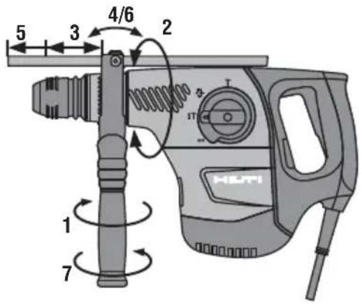
6.1 Fitting and adjusting the side handle 2
CAUTION
Removethedepthgauge from the side handle in to avoid injury.
-
Disconnect the supply cord plug from the outlet.
-
Release the side handle clamping band by turning the handle counterclockwise.
- Slide the side handle clamping band over the ch and onto the cylindrical section at the front end the power tool.
- Pivot the side handle into the desired position.
- Secure the side handle by turning the grip clockwise.
order
6.2 Unlocking the power tool
See section "Operation" power
6.3 Use of extension cords and generators or transformers
Please refer to section 2 "Description".
7 Operation


CAUTION
In accordance with the applications for which it signed, the power tool produces a high torque. use the side handle and hold the power to hands. The user must be prepared for sudden and stalling of the insert tool.
CAUTION
Use clamps or a vice to hold the workpiece
CAUTION
The collar at the front end of the gearing section not to be used as a gripping surface.
CAUTION
Check the insert tool for damage or uneven wear time before use.
Always
7WithPrephing for use
sticking CAUTR
Wear protective gloves when changing insert tools the insert tools get hot during use.
7.1.1 Adjusting the depth gauge 3
- Release the side handle clamping band by the handle counterclockwise.
- Pivot the side handle into the desired position
- Attach the clamp with the depth gauge to ingbandatthedesiredposition.
- Release the screw at the depth gauge.
- Adjust the depth gauge to the desired drill
- Tighten the screw at the depth gauge firmly
- Tighten the side handle securely by turning the grip section. This also clamps the depth gauge position.
7.1.2 Fitting the insert tool 4
- Disconnect the supply cord plug from the outlet.
- Check that the connection end of the insert clean and lightly greased. Clean it and grease necessary.
- Check that the sealing lip of the dust shield clean and in good condition. Clean the dust if necessary or have it replaced if the seat damaged.
- Push the insert tool into the chuck and ro applying slight pressure until it engages in grooves.
- Push the insert tool further into the chuck heard to engage.
- Check that the insert tool has engaged con pulling it.
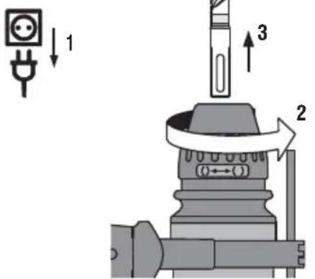
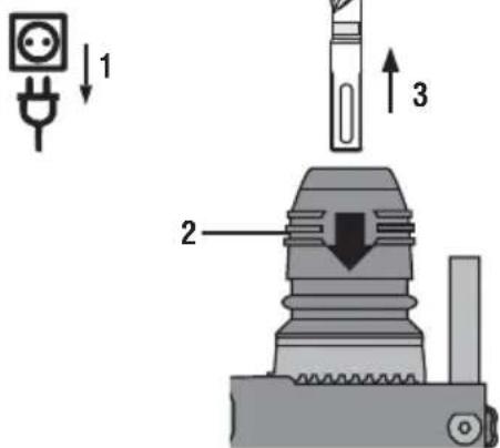
7.1.3 Removing the insert tool 5
- Disconnect the supply cord plug from the outlet.
- Open the chuck by pulling back the inserting sleeve.
- Pull the drill bit out of the chuck.
7.1.4 Removing the chuck 6
CAUTION
Remove the depth gauge from the side hand the insert tool from the chuck in order to
NOTE
Set the selector switch to the “Chiseling” posit removing the chuck.
- Disconnect the supply cord plug from the outlet.
- Pull the chuck sleeve forward and hold it
- Remove the chuck by pulling it away from tool.
7.1.5 Fitting the chuck 7
CAUTION
Remove the depth gauge from the side hand the insert tool from the chuck in order to
NOTE
Set the selector switch to the “Chiseling” posit removing the chuck.
- Disconnect the supply cord plug from the power winding outlet.
- Grip the chuck sleeve, pull it forward and hold it securely in this position.
- Slide the chuck onto the guide tube from the first clamp and then release the sleeve.
- Rotate the chuck until it is heard to engage.
7.2 Operation

CAUTION
Working on the material may cause it to splinter. We feel protection and protective gloves. Wear breathing as protection if no dust removal system is used. Splittering material presents a risk of injury to the eyes
elbody.
st shield
CAUTION aling lip is
The work generates noise. Wear ear protectors. Expcure to noise can cause hearing loss.
the guide
CAUTION
Improve the blood circulation in your fingers by relaxing your hands and exercising your fingers during breaks between working.
7.2.1 TPS theft protection system (optional)
NOTE
The power tool may be equipped with the optional protection system. If the power tool is equipped with featureock-it can be unlocked and made ready for open only through use of the corresponding TPS key.
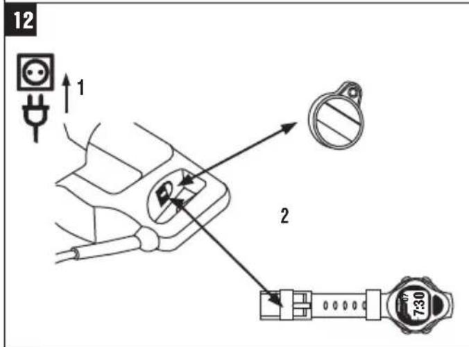
7.2.1.1 Unlocking the power tool 8
- Plug the supply cord into the power outlet. The
yellow theft protection indicator LED blinks. The
Ile answer tool is now ready to receive the signal if avoid the injury. - Hold the TPS key or the TPS watch strap buckle against the lock symbol. The power tool is unlocked beforeon as the yellow theft protection indicator I no longer lights.
NOTE If, for example, the electric supply is brief power interrupted due to a power failure or disconnected when moving to a different workplace, the power securely tool remains ready for operation for approx. 20 the minutes. In the event of a longer interruption, the TPS key must be used again to unlock the po tool.
7.2.1.2 Activation of the theft protection system fo
the power tool
aNOTE injury.
Further detailed information on activation and use of theft protection system can be found in the operating instructions for the theft protection system.
7.2.2 Drilling without hammering (A) 9
- Turn the function selector switch until it eng the "Drilling without hammering" position. Do operate the function selector switch while this is running.
- Bring the side handle into the desired position check that it is fitted correctly and secured
- Plug the supply cord into the power outlet.
- Position the power tool and drill bit at the where the hole is to be drilled.
- Press the control switch slowly (drill at a until the drill bit centers itself in the hole)
- Press the control switch fully to continue of full power.
- Do not apply excessive pressure. This crease the power tool's drilling performance. pressure extends the life of the insert tool
7.2.3 Hammer drilling (B) 9
NOTE
Working at low temperatures: The hammering manism works only when the power tool has re minimum operating temperature. Bring the tip of bit or chisel into contact with the workpiece a the power tool to run under no load until it the minimum operating temperature. If necessary, this procedure until the hammering mechanism b operate.
- Turn the function selector switch until it ends the "Hammer drilling" position. Do not open function selector switch while the motor is
- Bring the side handle into the desired position check that it is fitted correctly and secured
- Plug the supply cord into the power outlet.
-
Position the power tool and drill bit at the where the hole is to be drilled.
-
Press the control switch slowly (drill at a low sp until the drill bit centers itself in the hole).
- Press the control switch fully to continue drilling not full power.
- Do not apply excessive pressure. This will not increase the power tool's hammering performance. on and Lower pressure extends the life of the insert too
- Reduce drilling speed shortly before breaking point through in order to avoid damage to the en the rear side.
ow speed
7.2.4 Chiseling
NOTE rilling with
The chisel can be adjusted to 12 different positions (in 30^ increments). This ensures that flat chisels and shaped chisels can always be set to the optimum w position.
7.2.4.1 Adjusting the chisel (C) 9
CAUTION
Do not operate the power tool when the selector switches to "Chisel adjustment".
the drill
and. allow the function selector switch until it engages the "Chisel adjustment" position. Do not operate a function selector switch while the motor is running begins. Bring the side handle into the desired position and check that it is fitted correctly and secured.
- Rotate the chisel to the desired position.
ate7.24e2 Locking the chisel (D) 9
running the function selector switch until it engages in tion Chiseing" position. Do not operate the function select . switch while the motor is running.
p724.3 Chiseling(D) 9
- Plug the supply cord into the power outlet.
- Position the tip of the chisel at the point where chiseling is to begin.
- Press the control switch fully.
8 Care and maintenance
CAUTION
Disconnect the mains plug from the power
8.1 Care of insert tools
Clean off dirt and dust deposits adhering to the tools and protect them from corrosion by wiping insert tools from time to time with an oil-soaked
8.2 Care of the power tool
outlet CAUTION
Keep the power tool, especially its grip surfaces, clean and free from oil and grease. Do not use inser agents which contain silicone.
the Never operate the power tool when the ventilation sl are blocked. Clean the ventilation slots carefully using a dry brush. Do not permit foreign objects to enter interior of the power tool. Clean the outside of the tool at regular intervals with a slightly damp cloth. I not use a spray, steam pressure cleaning equipment running water for cleaning. This may negatively affect electrical safety of the power tool.
8.3 Service indicator
NOTE
The power tool is equipped with a service indicator.
Indicator Constant red light End of service interval - servicing is due.
After the lamp lights for the first time, the power tool may continue to be used for several hours before the automatic cut-out is activated. To ensure that the power tools always ready for use, it should be returned to Hilti for servicing in good time.
Blinking red light See section "Troubleshooting".
8.4 Maintenance
WARNING
Repairs to the electrical section of the power tool may be carried out only by trained electrical specialists.
Check all external parts of the power tool for at regular intervals and check that all controls faultlessly. Do not operate the power tool if p
damaged or when the controls do not function fault. If necessary, the power tool should be repaired by
Service. tool may alists.
8.5 Checking the power tool after care and damage maintenance
Aerate carrying out care and maintenance work on the power tool, check that all protective and safety device are fitted and that they function faultlessly.
9 Troubleshooting
Fault Possible cause Remedy
| The power tool doesn't start. | Interruption in the electric supply. | Plug in another electric appliance and check whether it works. |
| The supply cord or plug is defective. | Have it checked by a trained electrical specialist and replaced if necessary. | |
| Generator with sleep mode. | Apply a load to the generator by necting another appliance (e.g. a lamp). Subsequently switch the power tool off and on again. | |
| Other electrical fault. | Have it checked by a trained electric specialist. | |
| The electronic restart interlock is activated after an interruption in the electric supply. | Switch the power tool off and on | |
| No hammering action. | The power tool is too cold. | Allow the power tool to warm up to the minimum operating temperature.See section: 7.2.3 Hammer drilling (B) 9 |
| The power tool doesn't start A fault has occurred in the power tool and the LED blinks red. | If necessary, the power tool should be repaired by Hilti Service. | |
| The power tool doesn't start The carbon brushes are worn. | Have it checked by a trained ele specialist and replaced if necessary. | |
| The power tool doesn't start The power tool has not been unUse the TPS key to unlock the power yellow. | Use the TPS key to unlock the power yellow. | |
| The power tool doesn't achieve the extension cord is too long Gauge is inadequate. | Use the extension cord of an approved length and / or of adequate gauge. | |
| Connect the power tool to a different power source. | ||
Fault Possible cause Remedy
| The drill bit doesn’t rotate. | The function selector switch is not engaged or is in the “Chiseling” the function control switch to the “Chisel adjustment” position. | When the motor has stopped, move the function control switch to the “Drilling without hammering” or “Hammer drilling” position. |
| The drill bit / chisel can’t leased from the chuck. | The rechuck is not pulled back fully. Pull the chuck back as far as it and remove the insert tool. | |
| The side handle is not fitted correctly. Release the side handle an it correctly so that the clamping band and side handle engage in the groove. | ||
10 Disposal

Most of the materials from which Hilti power tools or appliances are manufactured can be recycled. The materials must be correctly separated before they can be recycled. In many countries, Hilti has already made arrangements for taking back your old power tools or appliances for recycling. Please ask your Hilti customer service department or Hilti representative for further information.

For EC countries only
Disposal of electric tools together with household waste is not permissible.
In observance of the European Directive on waste electrical and electronic equipment and its implementation in accordance with national law, electrical appliances that have reached the end of their life must be collected separately and returned to an environmentally compatible recycling facility.
11 Manufacturer's warranty - tools
Please contact your local Hilti representative if you have questions about the warranty conditions.
12 EC declaration of conformity (original)
| Designation: Combihammer |
| Type: TE 40 / TE 40-AVR |
| Year of design: 2006 |
We declare, on our sole responsibility, that this complies with the following directives and standa 2006/42/EC, 2004/108/EC, 2011/65/EU, EN 60745-EN 60745-2-6, EN ISO 12100.
Hilti Corporation, Feldkircherstrasse 100, FL-9494 Schaan

Paolo Luccini Jan Doongaji
Head of BA Quality and Process Management Business Area Electric Tools & Accessories 01/2012 01/2012 Executive Vice President Business Unit Power Tools & Accessories
Technical documentation filed at:
86916 Kaufering product
Deutschland
TE 40 / TE 40-AVR Kombikalapács
Head of BA Quality and Process Management Business Area Electric Tools & Accessories 01/2012 01/2012 Executive Vice President Business Unit Power Tools & Accessories
Head of BA Quality and Process Management Executive Vice President Business Area Electric Tools & Accessories Business Unit Powers 01/2012 01/2012 Tools & Accessories
Head of BA Quality and Process Management Executive Vice President Business Area Electric Tools & Accessories Business Unit Power Tools & Accessories 01/2012 01/2012
Head of BA Quality and Process Management Executive Vice President
Business Area Electric Tools & Accessories 01/2012 Business Unit Power Tools & Accessories 01/2012
Head of BA Quality and Process Management Business Area Electric Tools & Accessories 01/2012 01/2012 Executive Vice President Business Unit Power Tools & Accessories
Head of BA Quality and Process Management Business Area Electric Tools & Accessories 01/2012 01/2012 Executive Vice President Business Unit Power Tools & Accessories
Head of BA Quality and Process Management
Business Area Electric Tools & Accessories
01/2012 01/2012
Executive Vice President
Business Unit Power
Tools & Accessories
Paolo Luccini Jan Doongaji
Head of BA Quality and Process
Management
Business Area Electric Tools &
Accessories
01/2012 01/2012
Executive Vice President
Business Unit Power
Tools & Accessories
Head of BA Quality and Process
Management
Business Area Electric Tools &
Accessories
01/2012 01/2012
Executive Vice President
Business Unit Power
Tools & Accessories
2.7 Active Vibration Reduction (numai TE 40-AVR)
Head of BA Quality and Process Mana- Executive Vice President
gement
Business Area Electric Tools & Acces-
sories
01/2012 01/2012
Executive Vice President
Business Unit Power
Tools & Accessories
01/2012

Paolo Luccini
Head of BA Quality and Process
Management
Business Area Electric Tools &
Accessories
01/2012
7.2.2 Darbesiz delme (A) 9
Head of BA Quality and Process
Management
Business Area Electric Tools &
Accessories
01/2012 01/2012
Executive Vice President
Business Unit Power
Tools & Accessories
Head of BA Quality and Process
Management
Business Area Electric Tools &
Accessories
01/2012 01/2012
Executive Vice President
Business Unit Power
Tools & Accessories
技術資料:
2.7 Active Vibration Reduction (TE 40-AVR만)

Paolo Luccini Jan Doongaji
Head of BA Quality and Process Executive Vice President Management Business Area Electric Tools & Accessories 01/2012 01/2012 Business Unit Power Tools & Accessories
기술 문서 작성자:
TE 40 / TE 40-AVR 鑽鑿兩用電鎚鑽
第一次使用機具前,先務必閱讀操作說明。
務必將操作說明和機具放在一起。
Head of BA Quality and Process
Management
Business Area Electric Tools &
Accessories
01/2012 01/2012
Executive Vice President
Business Unit Power
Tools & Accessories
技術文件歸檔於:
Head of BA Quality and Process
Management
Business Area Electric Tools &
Accessories
01/2012 01/2012
Executive Vice President
Business Unit Power
Tools & Accessories
技术文档提交于:
Hilti = registered trademark of Hilti Corp., Schaan
W 3161 | 0514 | 00-Pos. 8 | 1
Printed in Germany © 2014
Right of technical and programme changes reserved S. E. & O.
274309/A3


- TE 40 / TE 40-AVR Kombihammer
- Jan Doongaji
- re to operating controls and indicators 1
- General information
- Safety notices and their meaning
- DANGER
- WARNING
- CAUTION
- NOTE
- Explanation of the pictograms and other information
- Description
- Use of the product as directed
- Chuck
- Switches
- Grips
- Protective device
- Lubrication
- Active vibration reduction (only TE 40-AVR)
- TPS theft protection system (optional)
- LED indicators
- Items supplied as standard
- Using extension cords
- Using extension cords outdoors
- Using a generator or transformer
- Technical data
- Safety instructions
- General Power Tool Safety Warnings
- Work area safety
- Electrical safety
- Service
- Hammer safety warnings
- Additional safety instructions
- Personal safety
- Power tool use and care
- Electrical safety
- Work area safety
- Beforeuse
- Fitting and adjusting the side handle 2
- Operation
- Adjusting the depth gauge 3
- Fitting the insert tool 4
- Removing the insert tool 5
- Removing the chuck 6
- Fitting the chuck 7
- Operation
- CAUTION aling lip is
- TPS theft protection system (optional)
- Unlocking the power tool 8
- Activation of the theft protection system fo
- the power tool
- aNOTE injury.
- Drilling without hammering (A) 9
- Hammer drilling (B) 9
- ow speed
- Chiseling
- NOTE rilling with
- Adjusting the chisel (C) 9
- ate7.24e2 Locking the chisel (D) 9
- p724.3 Chiseling(D) 9
- Care and maintenance
- Care of insert tools
- Care of the power tool
- outlet CAUTION
- Service indicator
- Maintenance
- Troubleshooting
- Disposal
- Manufacturer's warranty - tools
- EC declaration of conformity (original)
- TE 40 / TE 40-AVR Kombikalapács
- Active Vibration Reduction (numai TE 40-AVR)
- Paolo Luccini
- Darbesiz delme (A) 9
- 技術資料:
- Active Vibration Reduction (TE 40-AVR만)
- TE 40 / TE 40-AVR 鑽鑿兩用電鎚鑽
- 技術文件歸檔於:
- 技术文档提交于:
Brand : HILTI
Model : TE 40-AVR
Category : Drill