
RDS1 SB-C SB-M - Electronic module KARCHER - Free user manual and instructions
Find the device manual for free RDS1 SB-C SB-M KARCHER in PDF.
User questions about RDS1 SB-C SB-M KARCHER
0 question about this device. Answer the ones you know or ask your own.
Ask a new question about this device
Download the instructions for your Electronic module in PDF format for free! Find your manual RDS1 SB-C SB-M - KARCHER and take your electronic device back in hand. On this page are published all the documents necessary for the use of your device. RDS1 SB-C SB-M by KARCHER.
USER MANUAL RDS1 SB-C SB-M KARCHER
Deutsch 3
English 6
Français 9
Italiano 12
Nederlands 15
Español 18
Português 21
Norsk 24
Svenska 27
Suomi 30
Ελληνικά 33
Türkçe 36
Русский 39
Magyar 42
Polski 45
Register and win! www.kaercher.com

F:224=Sicher. Brenner
Please read and comply with these instructions prior to the
initial operation of your appliance. Retain these operating instructions for future reference or for subsequent possessors.
Environmental protection

The packaging material can be recycled. Please do not place the package to the ordinary refuse for disposal, but ge for the proper recycling.

Old appliances contain valuable materials that can be recycled. Please arrange for the proper recycling of old
appliances. Batteries and accumulators contain substances that must not enter the environment. Please dispose of your old appliances, batteries and accumulators using appropriate collection systems.
Notes about the ingredients (REACH)
You will find current information about the ingredients at:
www.kaercher.com/REACH
Safety instructions
General
To avoid danger to persons, animals and property before the first operation of the system, read:
– this operating instructions manual
– the operating instructions manual of the car washing unit associated with the controls
– all safety instructions
– the respective national statutes of the legislator
For the operation of this system the following regulations and directives are applicable in the Federal Republic of Germany (available from Carl Heymanns Verlag KG, Luxemburger Straße 449, 50939 Cologne):
- Accident prevention provision "General rules and regulations" BGV A1
– Order in respect of operational safety (BetrSichV).
Ensure:
- that you have understood all the instructions
- that all users of the plant are informed about the instructions and have understood them.
The following symbols are used in this operating manual:
⚠️ Danger
indicates an immediate threat of danger. Failure to observe the instruction may result in death or serious injuries.
⚠ Warning
indicates a possibly dangerous situation. Failure to observe the instruction may result in light injuries or damage to property.
Note
indicates useful tips and important information.
Proper use
The RDS1 can be used for monitoring and remote switching an SB washing system via SMS.
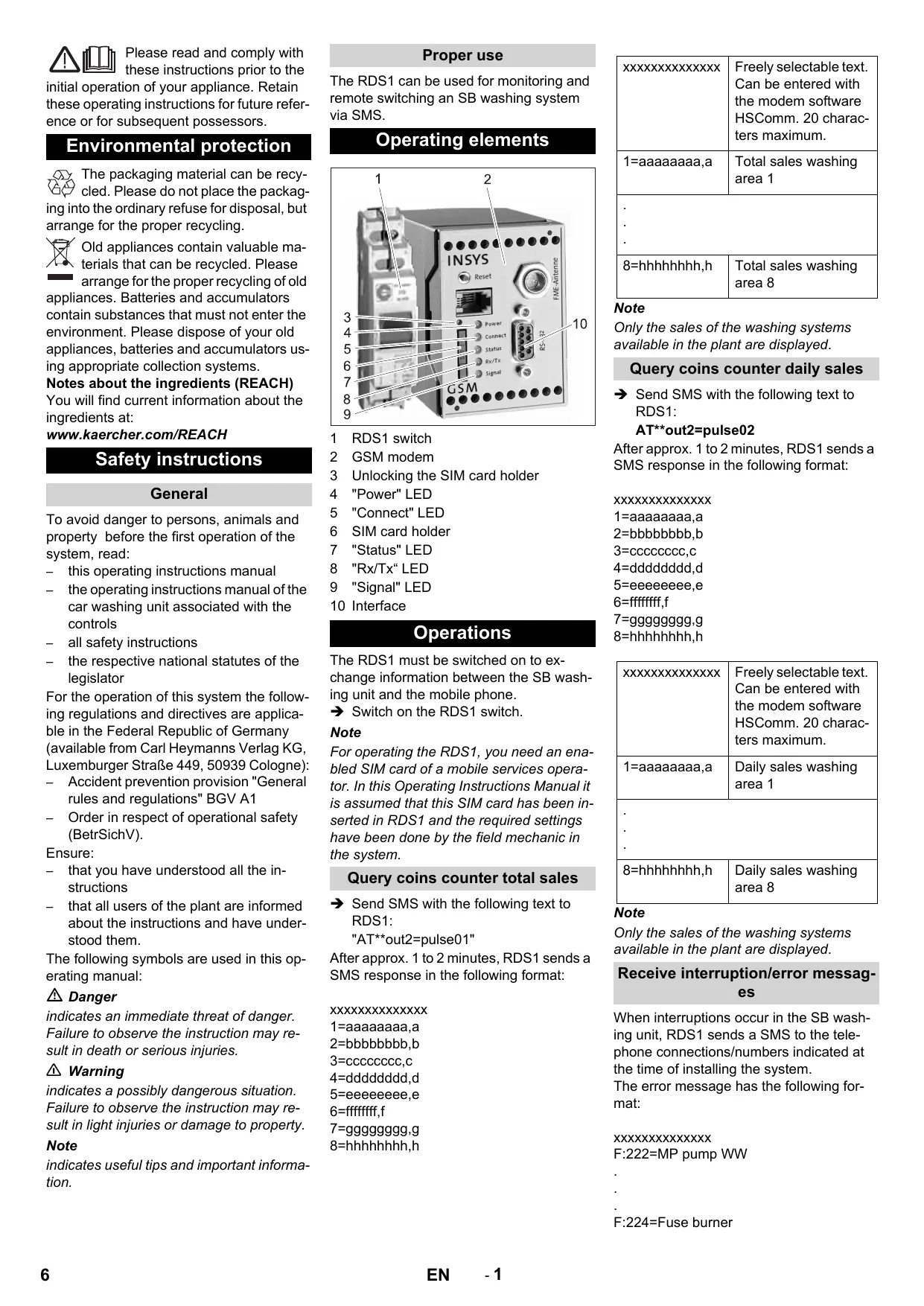
Operating elements
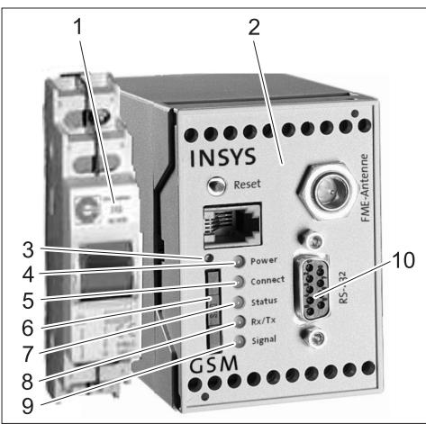
1 RDS1 switch
2 GSM modem
3 Unlocking the SIM card holder
4 "Power" LED
5 "Connect" LED
6 SIM card holder
7 "Status" LED
8 "Rx/Tx" LED
9 "Signal" LED
10 Interface
Operations
The RDS1 must be switched on to exchange information between the SB washing unit and the mobile phone.
→ Switch on the RDS1 switch.
Note
For operating the RDS1, you need an enabled SIM card of a mobile services operator. In this Operating Instructions Manual it is assumed that this SIM card has been inserted in RDS1 and the required settings have been done by the field mechanic in the system.
Query coins counter total sales
→ Send SMS with the following text to RDS1:
"AT**out2=pulse01"
After approx. 1 to 2 minutes, RDS1 sends a SMS response in the following format:
XXXXXXXXXXXXXX
1=aaaaaaa,a
2=bbbbbbbb,b
3=cccccccc,c
4=dddddddd,d
5=eeeeeee,e
6=ffffffff, f
7=ggggggggg,g
8=hhhhhhhh,h
| xxxxxxxxxxxxxx | Freely selectable text.Can be entered withthe modem softwareHSComm. 20 charac-ters maximum. |
| 1=aaaaaaa,a | Total sales washingarea 1 |
| .. | |
| 8=hhhhhhh,h | Total sales washingarea 8 |
Note
Only the sales of the washing systems available in the plant are displayed.
Query coins counter daily sales
→ Send SMS with the following text to RDS1:
AT\*\*out2=pulse02
After approx. 1 to 2 minutes, RDS1 sends a SMS response in the following format:
XXXXXXXXXXXXXX
1=aaaaaaa,a
2=bbbbbbbb,b
3=cccccccc,c
4=dddddddd,d
5=eeeeeee,e
6=ffffffff, f
7=ggggggggg,g
8=hhhhhhhh,h
| xxxxxxxxxxxxxx | Freely selectable text.Can be entered withthe modem softwareHSComm. 20 charac-ters maximum. |
| 1=aaaaaaa,a | Daily sales washingarea 1 |
| .. | |
| 8=hhhhhhh,h | Daily sales washingarea 8 |
Note
Only the sales of the washing systems available in the plant are displayed.
Receive interruption/error messages
When interruptions occur in the SB washing unit, RDS1 sends a SMS to the telephone connections/numbers indicated at the time of installing the system.
The error message has the following format:
XXXXXXXXXXXXXX
F:222=MP pump WW
-
[Non-Text]
[Non-Text]
.
F:224=Fuse burner
| xxxxxxxxxxxxxx | Freely selectable text.Can be entered withthe modem softwareHSComm. 20 charac-ters maximum. |
| F:222=MPpump WW | Error message (ex-ample) |
| .. | |
| .. | |
| F:224=Fuseburner | Error message (ex-ample) |
Note
If there is no display text in the country's language, only the error code /F:XXX) will be sent.
If the system is locked due to an error, the message will have this note in the second line:
Unit disabled
Note
RDS1 sends the following message after all errors have been rectified:
XXXXXXXXXXXXXX
No faults
Error messages
The meaning of the error messages is described in the operating instructions manual of the washing unit or the water preparation.
Changing the settings
You need a PC to modify the settings. The enclosed configuration software from IN-SYS should be installed on the PC.
Changing the mobile services provider
Note
Before changing, check whether the desired mobile network is available where the plant/system is installed.
Keep the SIM card and the corresponding PIN number ready.
Only SIM cards with 3V power supply may be used. The voltage details are printed on the SIM card.
For prepaid cards, ensure that you have enough balance on the card.
→ Switch off the RDS1 switch.
→ Press release button of the SIM card holder.
→ Take out the SIM card holder.
→ Remove the SIM card from the card holder.
→ Re-insert the SIM card holder.
→ Disconnect serial cable between GSM modem and control at the controls and connect it to the PC.
→ Switch on RDS1 switch - the GSM modem will be initialised:
The "Connect" LED glows for approx. 4 seconds.
- after another 8 seconds the LED status starts to blink for approx. 20 seconds
The "Signal" LED displays the strength of the reception signal. Faster the LED blinks, so much better is the reception.
→ Start the configuration software "HSCom" on the PC.
The programme automatically establishes the link to the GSM modem.
If the message "Monitoring time expired" is displayed, it means the connection cannot be established automatically. In such a case, click the "Synchronise RS232" button followed by the "Read settings" button in the screen. This process can take approximately 1 minute. Repeat the process if error messages are displayed.
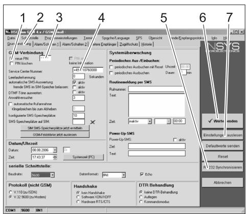
→ Activate the Basic Settings tab.
→ Activate the "New PIN" checkbox.
→ Enter the new PIN for the SIM Card in the PIN input field.
→ Enter the Service Centre Number of the mobile operator in the Service Center Number field.
Note
The Service Centre Number is needed for sending SMS and can be found in the documents of the mobile phone operator.
Some Service Centre numbers are given in the appendix to the manual of the GSM modem.
→ Click "Send values" button
Note
Repeat the process if error messages are displayed.
The new PIN is stored in the GSM modem and is used for logging on to the GSM network during every fresh start.
→ Exit the configuration program on the PC.
→ Switch off the RDS1 switch.
→ Press release button of the SIM card holder.
→ Take out the SIM card holder.
→ Place the new SIM card in the card holder.
→ Re-insert the card holder with SIM card - the contacts of the SIM card must point towards the left.
→ Disconnect serial cable at PC and connect it to the controls of the SB washing unit.
→ Switch on the RDS1 switch - the initialisation process will be run.
The initialization process is completed after approx. 90 seconds.
The "Power" and "Status" LEDs start to glow.
The "Signal" LED displays the strength of the reception signal. Faster the LED blinks, so much better is the reception.
Change the receiver of messages
→ Switch off the RDS1 switch.
→ Disconnect serial cable between GSM modem and control at the controls and connect it to the PC.
→ Switch on RDS1 switch - the GSM modem will be initialised:
The "Connect" LED glows for approx. 4 seconds.
- after another 8 seconds the LED status starts to blink for approx. 20 seconds
The "Signal" LED displays the strength of the reception signal. Faster the LED blinks, so much better is the reception.
→ Start the configuration software "HSCom" on the PC.
The programme automatically establishes the link to the GSM modem.
Note
If the message "Monitoring time expired" is displayed, it means the connection cannot be established automatically. In such a case, click the "Synchronise RS232" button followed by the "Read settings" button in the screen. This process can take approximately 1 minute. Repeat the process if error messages are displayed.
→ Click "Alarm/Switch1" tab; you can now modify the settings given below it.
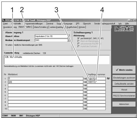
1 Starting text of the message, for e.g. location or description of the unit, max. length 20 characters
2 "Alarm/Switch1" tab
3 Telephone number to which the interruption messages are sent
4 Telephone number where the feedback is to be sent during remote operations
Note
Feedback during remote operations can only be sent to the receivers who have been registered in this screen.
Setting up additional receivers for fault messages
In addition to the receivers mentioned above, messages can also be sent simultaneously to other telephone numbers.
→ Click "Other Receivers" tab.
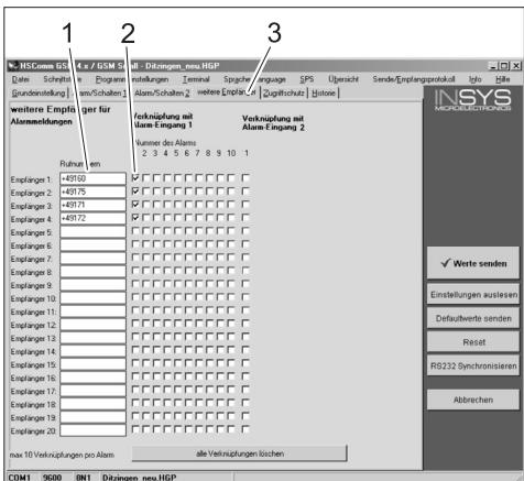
1 List of telephone numbers
2 Fault/error messages
3 "Other Receivers" tab.
- You can enter a maximum of 20 different additional receivers in the list of telephone numbers.
– Each message can be sent to a maximum of 10 receivers. - The respective message is sent to the receivers who are checked in the column for the message with a tick mark.
Selective Call Acceptance
Note
Activating the selective call acceptance prevents other callers from scanning the data of the plant. Then only the SMS commands sent by registered telephone numbers will be accepted.
The transmission of telephone numbers must be activated on the caller's telephone.
→ Click "Access Protection" tab; you can now modify the settings given below it.
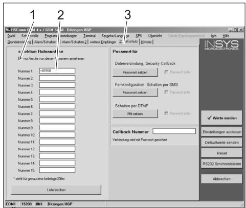
1 Tick mark = Selective call acceptance is active
2 List of telephone numbers that are allowed to remotely operate the SB washing unit
3 "Access Protection" tab
Apply settings
→ When all settings are completed, click "Send values" button.
Note
If an error message occurs while sending the value, repeat the process.
→ Save settings on the PC: Clcik "File" in the menu bar, click "Save File As", enter the file name and save the file.
→ Exit the configuration program on the PC.
→ Switch off the RDS1 switch.
→ Disconnect serial cable at PC and connect it to the controls of the SB washing unit.
→ Switch on the RDS1 switch - the initialisation process will be run.
The initialization process is completed after approx. 90 seconds.
The "Power" and "Status" LEDs start to glow.
The "Signal" LED displays the strength of the reception signal. Faster the LED blinks, so much better is the reception.
Check function
→ Release the fault in the unit (for e.g. press engine protection switch).
- The GSM modem will generate a message approx. 20 seconds after the occurrence of the fault. You can hear the switching of the alarm output on the modem.
- A short while later, the recipients that have been entered will receive a corresponding SMS.
→ Query counter status - according to description in the chapter "Query counter statuses".
- After 1 to 2 minutes, the response will reach the designated receivers.

www.kaercher.com/REACH
www.kaercher.com/REACH
Norme di sicurezza
Norme generali
www.kaercher.com/REACH
www.kaercher.com/REACH
1=aaaaaaa,a
2=bbbbbbb,b
3=cccccccc,c
4=dddddddd,d
5=eeeeeee,e
6=ffffffff, f
7=ggggggggg,g
8=hhhhhhhh,h
www.kaercher.com/REACH
Avisos de segurança
Generalidades
www.kaercher.com/REACH
www.kaercher.com/REACH
LED "Connect" lyser under ca. 4 sekunder.
Efter ytterligare 8 sekunder blinkar LED "Status" under ca. 20 sekunder.
www.kaercher.com/REACH
Turvaohjeet
Yleistä
www.kaercher.com/REACH
www.kaercher.com/REACH
Güvenlik uyarıları
Genel
www.kaercher.com/REACH
www.kaercher.com/REACH
Biztonsági tanácsok
Általános
1=aaaaaaa,a
2=bbbbbbbb,b
3=cccccccc,c
4=dddddddd,d
5=eeeeeee,e
6=ffffffff, f
7=ggggggggg,g
8=hhhhhhhh,h
www.kaercher.com/REACH
XXXXXXXXXXXXXX
1=aaaaaaa,a
2=bbbbbbb,b
3=cccccccc,c
4=dddddddd,d
5=eeeeeee,e
6=ffffffff, f
7=ggggggggg,g
8=hhhhhhhh,h