
FUSG30010 - Alarm bell ABUS - Free user manual and instructions
Find the device manual for free FUSG30010 ABUS in PDF.


| Product type | Alarm siren |
| Brand | ABUS |
| Model | FUSG30010 |
| Dimensions (L x W x H) | 120 x 80 x 60 mm |
| Weight | 200 g |
| Power supply | 9V battery (type 6LR61) |
| Sound volume | 105 dB at 1 m |
| Sound frequency | 2.5 kHz |
| Protection | IP54 (splash resistant) |
| Operating temperature | -10 °C to +50 °C |
| Battery life | Up to 2 years in standby |
| Main functions | Powerful siren, tamper detection, status LED indicator, operational test |
| Compatibility | Compatible with ABUS alarm systems (including Secvest, Terxon, etc. control panels) |
| Installation | Wall mounting, wireless (868 MHz radio link) |
| Radio range | Up to 100 m in open field |
| Housing material | UV-resistant ABS |
| Color | White |
| Care and cleaning | Wipe with a soft, dry cloth; do not use solvents |
| Safety | Anti-tamper contact, short-circuit protection |
| Spare parts and repairability | User-replaceable battery; no other spare parts available |
| Package contents | Alarm siren, 9V battery, mounting kit, user manual |
| Warranty | 2 years |
Frequently Asked Questions - FUSG30010 ABUS
User questions about FUSG30010 ABUS
0 question about this device. Answer the ones you know or ask your own.
Ask a new question about this device
Download the instructions for your Alarm bell in PDF format for free! Find your manual FUSG30010 - ABUS and take your electronic device back in hand. On this page are published all the documents necessary for the use of your device. FUSG30010 by ABUS.
USER MANUAL FUSG30010 ABUS
natural_image
Transparent rectangular container with a black lid and visible side labels (no text or symbols on the container itself)
natural_image
Pure electrical circuit lines without any symbols© Copyright 2007 by Security-Center GmbH & Co. KG. Printed in Israel.
CE @ www.security-center.org/CE
Inhalt
Einleitung .... 3
natural_image
Gray rectangular panel with horizontal slats, no visible text or symbols
Alarm and tamper signalling....14
Battery monitoring....14
Supervision 14
Pre-alarm function....14
Self-test....14
LED display....14
Installing the external sounder ....15
Installing the internal sounder 16
Programming 17
Programming menu....17
[9] [1] Allocation.... 17
[9] [2] Parameters.... 18
[9][3] Communication Test 19
[9][4] Calibration 20
[9][5] Tamper Mute 20
[1][1][9] Acc. SV time.... 20
[1][2][35] Siren Pre Alarm 21
Event memory 21
User Menu 22
Diagnostics.... 22
Siren Version....22
Changing the batteries.... 23
Technical data....23
Electrical 23
Wireless 23
Environment....23
Introduction
The battery-operated wireless sounders for your ABUS wireless alarm system offer you fast, flexible installation without elaborate cable-laying. The wireless sounders work bidirectional – i.e., radio signals are sent to the wireless sounders, and tamper messages are sent from the sounders to your alarm system.
Features
Alarm and tamper signalling
In the event of an alarm or tampering, the wireless sounders are activated and start to register an alarm visually and audibly. The alarm duration is defined by a setting in the programming menu. However, the maximum alarm time is limited to 5 minutes to save energy, regardless of the setting.
Battery monitoring
If the batteries are low, this is reported to the system.
Battery for radio transmitter/receiver
Φ Battery for audible/visual alert
Supervision
The wireless sounders send a signal to the system every 65 minutes. If the function is enabled, the system monitors the arrival of this signal.
Pre-alarm function
The pre-alarm function is an important security function. If it is enabled, the system sends a signal to the wireless sounders at the start of the entry delay period. This arms the wireless sounders. If they are not disarmed when the delay period expires, they automatically trigger an alarm. So if the system is destroyed within the entry delay period, an alarm is still sounded.
IMPORTANT:
This function must be enabled in the programming menu.
Self-test
Press the reset button on the PC board of the wireless sounder to run a self-test. If the sounder detects a fault, it is reported to the system. You can also start a test from the system.
LED display
The wireless sounders have 2 LEDs. The LEDs are active for 10 minutes after opening the tamper contact.
Red: Activates on sending
Yellow: Indicates a low battery
Red and yellow (3 seconds): Confirms successful learning
Installing the external sounder
1) Remove the screws on both sides of the external wireless sounder and open the cover of the sounder upwards.
2) Using the base plate as a drilling template, mark the drill holes on the wall. Drill the holes and insert the wall plugs.
3) Fix the sounder to the wall
4) Insert batteries supplied.
5) The external sounder is now ready to be trained for the ABUS wireless alarm system.
6) After the sounder is trained, close the lid and lock it with the screws on the side.

External Sounder - PCB Diagram
Installing the internal sounder
- Remove the casing screw from the base of the sounder.
- Remove the base plate from the internal sounder. Using the base plate as a drilling template, mark the drill holes.
- Drill the holes and insert wall plugs if required.
- Screw the base plate to the wall.
- Insert the batteries supplied (check polarity!).
- Train the sounder for the system.
- After training the sounder, mount it on the base plate and insert the casing screw.


Internal Sounder - PCB Diagram
Programming
The following section also appears in the installation instructions. Up to 3 wireless sounders (external or internal) can be trained for the system.
Read these instructions carefully before starting with programming.
Programming menu
To enter the Siren menu:
In the programming menu, press [9] to access the Siren menu.
[9] [1] Allocation
The sounder must be trained for the wireless alarm system.
Programming the sounder
- After opening the Siren menu, press [1] to access the Allocation menu.
- Select the ID number of the sounder.
- Press the button to select the sounder type and then press Enter:
Φ NONE: No sounder
Φ ODWS1: External wireless sounder
Φ INDWS1: Internal wireless sounder
IMPORTANT:
If you select NONE as the type, you are asked whether you want to delete the sounder.
-
Press 📄 to select whether the sounder should be audible on alarm [Y] or not [N] and press Enter [#].
-
Press 📄 to select whether the sounder should emit an audible signal to confirm activation or deactivation [Y] or not [N] and press Enter [#].
-
Press 📄 to select whether the sounder should emit a visual signal to confirm activation or deactivation [Y] or not [N] and press Enter [#].

IMPORTANT:
The setting for the visual signal is possible only for the external wireless sounder.
Reading the sounder
After programming the sounder, you have to read it in. You do this by sending a signal from the sounder to the system. Select one of these functions:
• Press [1] to read in another sounder ID.
- Press [2] to read in the selected sounder. After pressing [2], you have 255 seconds to send a signal from the sounder to the system. To send this signal:
a. Press the reset button on the sounder PCB for ca. 3 seconds.
b. After you release the reset button, you her a short beep and the external sounder flashes briefly. You now have 10 seconds to press the tamper contact of the sounder and keep it pressed for at least 3 seconds.
If the sounder is successfully read in, a confirmation signal is emitted.
- Press [3] to delete a sounder from the system.
- Press [4] to select whether the sounder is to be supervised or not.
[9] [2] Parameters
Under Parameters, you program the function characteristic of the sounder.
To access the Parameters menu:
-
In the programming menu, press [9] to access the Siren menu.
-
Press [2] to access the Parameters menu option.
-
Enter the ID number of the sounder you want to program and press [#].

NOTE:
On internal sounders, you can only adjust the volume.
Parameters
| Quick-Key | Menu option |
| [9][2][1] | Strobe control |
| Defines the duration of the visual signal. | |
| [9][2][1][1] | Always off |
| Visual signalling is deactivated. | |
| [9][2][1][2] | Follow bell |
| Visual signalling is activated together with audible signalling. | |
| [9][2][1][3] | Follow alarm |
Visual signalling is activated on alarm.
| [9][2][2]Strobe blink | |
| Defines the number of flashes per minute. | |
| [9][2][2]Strobe blink[1]..[5] | |
| [1] 20 times per minute [4] 50 times per minute[2] 30 times per minute [5] 60 times per minute[3] 40 times per minute | |
| [9][2][3]Strobe arm squawk 01 Range: 01-20 seconds | |
| Defines the time the sounder continues visual acknowledgement. | |
| NOTE: | |
| If visual acknowledgement is deactivated, this setting is irrelevant. | |
| [9][2][4]Volume | |
| Defines the volume of the sounder for different signallingings. | |
| [9][2][4][1]Ex/En volume | |
| The audible signal that is issued during the entry and exit delay period.Factory default: 0 (no signal) | |
| [9][2][4][2]Alarm volume | |
| The audible signal issued on an alarm.Factory default: 9 (loudest setting) | |
| [9][2][4][3]Squawk volume | |
| The audible signal issued after arming the systemFactory default: 9 (loudest setting) |
[9][3] Communication Test
Tests communication between the system and the sounder.
To access the Comm test menu:
- In the programming menu, press [9] to access the Siren menu.
- In the Siren menu, press [3] to activate the communication test. The system displays the signal strength.
IMPORTANT:
For a successful test, the displayed signal strength must be higher than the signal strength reached under menu option 4 for the background noise. (menu option [9][4])
[9][4] Calibration
Sets the background noise level for the sounder receiver.
To set the receiver of the sounder
- In the programming menu, press [9] to access the Siren menu.
- In the Siren menu, press [4] to calibrate the receiver.
- Select the corresponding sounder ID number.
- To calibrate the receiver automatically, press 📋 and select Y. Then confirm your input. The system now calibrates the receiver and displays the value.
- To confirm the displayed value, press Enter [#].
[9][5] Tamper Mute
This function is important if you want to open a read in sounder without triggering a tamper alarm. Activate this menu option once. The sounder tamper is then deactivated. You can now open the cases of all sounder without triggering a tamper alarm. Make sure you close the case before exiting the programming menu.
When you exit the programming menu, the sounder tamper contact is monitored again.
IMPORTANT:
A tamper alarm that was already triggered cannot be stopped by this action.
[1][1][9] Acc. SV time
| Timers | ||||
| Quick-Key | Menu | option | Default | Selection |
| [1][1][9] | Accessory Supervision Time | 058 00-255 minutes | ||
Defines the monitoring time for accessories such as interior and exterior wired sounders. To avoid false alarms, make sure that the monitoring time of the receiver is longer than the monitoring time for accessories.
IMPORTANT:
To avoid false alarms, make sure that the monitoring time of the receiver (menu option [1][3][3]) is longer than the supervision time for accessories.
[1][2][35] Siren Pre Alarm
This menu item enables you to protect your system even better against tampering since the sounders can trigger an alarm independently of the system.
System control
| Quick-Key | Menu option | Default |
| [1][2][35] | Siren Pre Alarm | NO |
An important security aspect for your security system if you have fitted internal and external sounders.
YES: At the start of the entry delay time, the system sends a signal to the trained sounders. If no second signal is sent to the sounder following expiry of the delay time (since the system may have been destroyed or tampered with), the sounders trigger an alarm.
NO: The function is deactivated. The sounders start to sound an alarm when addressed by the system.
Event memory
The following table provides an overview of relevant entries in the event memory.
| LCD Text Event Description | |
| Tamper Siren=X Tamper alarm from wireless sounder X | |
| Tmp rstr Siren=X Tamper alarm restore from wireless sounder X | |
| Spkr low bat S=X Speaker low battery trouble | |
| Spkr I.bat rsS=X Speaker low battery restore from sounder X | |
| Radio I.bat S=X Radio low battery trouble | |
| Radio I.bat rs=X Radio (Transceiver) low battery restore from sounder X | |
| Siren=X Lost Sounder X is regarded as lost following supervision test. | |
| Siren=X Lost Rst | The System received a signal from sounder X after it has been regarded as lost |
User Menu
Diagnostics
In the Diagnostics menu, you can test the functioning of trained sounders.
To performe diagnostics
-
The system must be deactivated. Press the star button [*] to access the user menu and then [4] for the Maintenance menu option.
-
Enter the programmer PIN: In the factory setting, this is 0133.
- Press Enter [#].
- Press [7][1] to access the sounder test menu.
- Enter the ID number of the sounder you want to test. Press Enter [#].
The system now tests communication with the sounder and checks the state of the wireless sounder batteries and the audible/visual alarm.
- Press the arrow buttons to see the result.
IMPORTANT:
The test can also be started with the Upload/Download software.
Maintenance
Quick-Key Menu option
[4][7][1]Siren Diagnostics
Speakers batteries voltage: Shows the strength of the battery for the audible/visual alarm.
Radio batteries voltage: Shows the strength of the battery for the wireless transmitter.
Siren Version
Press [7] [2] to see the sounder version of the selected sounder.
Maintenance
Quick-Key Menu option
[4][7][2]Siren Version
Sounder part number:
F=Frequency (868MHz / 433MHz) V=Siren type (Internal/External), C= lens Color
Φ Sounder software version
Φ Sounder software date
Sounder software checksum
Changing the batteries
- Disable the tamper function of the sounders in the programming menu.
- Remove the sounder casing.
IMPORTANT:
If a tamper alarm is triggered despite the deactivation, press the RESET button on the PCB of the sounder.
- Remove all old batteries and replace them by new batteries.
- Press the RESET button.
- Close the casing and replace and tighten the screws of the sounder casing.
Technical data
Electrical
| Voltage supply 5 x CR123, 3V Lithium batteries | |
| 3 batteries for the wireless system | |
| 2 batteries for signalling | |
| Battery lifetime 3 years (typical) | |
| Sounder volume 105 dB @ 1 meter (adjustable) | |
| Material flash calotte Polycarbonate, red | |
| Flash frequency (external sounder) | 60 x per second (max.) |
| Dimensions, external sounder (HxWxD) | 300x 325x70 mm (11.8 x 12.8 x 2.8 inch) |
| Dimensions, internal sounder (HxWxD) | 145 x 120 x 50 mm |
| Weight, external sounder (including battery) | 1 Kg |
| Weight, internal sounder (including battery) | 0.44Kg |
Wireless
| Wireless technology Bidirectional narrow band | ||
| Frequency | 868 | MHz |
| Range 150m typical in open country | ||
| Monitoring | YES | |
| Modulation | AM | |
Environment
Temperature range -25°C to 60°C
IP class IP 44
Environment class Class IV
Sommaire
Introduction.... 25
[9] [1] Affectation 28
[9] [2] Paramètres.... 29
[9][3] Test de communication 30


[9][5] Protection anti-sabotage
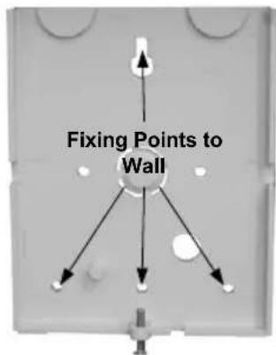

External Sounder - PCB Diagram
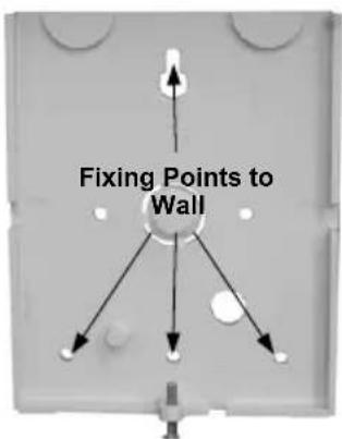
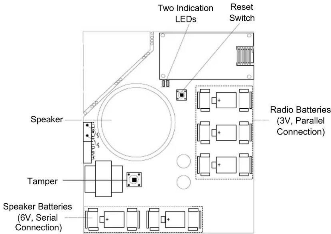
Internal Sounder - PCB Diagram
Programmering
- Inhalt
- Einleitung .... 3
- Programming 17
- Changing the batteries.... 23
- Technical data....23
- Introduction
- Features
- Alarm and tamper signalling
- Battery monitoring
- Supervision
- Pre-alarm function
- IMPORTANT:
- Self-test
- LED display
- Installing the external sounder
- Installing the internal sounder
- Programming
- Programming menu
- To enter the Siren menu:
- [9] [1] Allocation
- Programming the sounder
- Reading the sounder
- [9] [2] Parameters
- To access the Parameters menu:
- NOTE:
- [9][3] Communication Test
- To access the Comm test menu:
- [9][4] Calibration
- To set the receiver of the sounder
- [9][5] Tamper Mute
- [1][2][35] Siren Pre Alarm
- Event memory
- User Menu
- Diagnostics
- To performe diagnostics
- Maintenance
- Siren Version
- Changing the batteries
- Technical data
- Environment
- Sommaire
- Introduction.... 25
- [9][5] Protection anti-sabotage
- Programmering
Brand : ABUS
Model : FUSG30010
Category : Alarm bell