
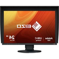
RX440-BK - Monitor EIZO - Free user manual and instructions
Find the device manual for free RX440-BK EIZO in PDF.


| Product type | Medical monitor |
| Brand | Eizo |
| Model | RX440-BK |
| Dimensions (W x H x D) | 360 x 440 x 80 mm |
| Weight | 8,5 kg |
| Power supply | 100-240 V AC, 50/60 Hz |
| Power consumption | 45 W (typical), 0,5 W in standby |
| Screen size | 30 inches (76,2 cm) |
| Native resolution | 2560 x 1600 (WQXGA) |
| Panel type | IPS LED |
| Contrast ratio | 1000:1 |
| Brightness | 350 cd/m² |
| Response time | 6 ms (gray to gray) |
| Viewing angle | 178° horizontal / 178° vertical |
| Connectivity | DisplayPort, DVI-D, USB 3.0 |
| Key features | DICOM calibration, LED backlight, built-in brightness sensor |
| Maintenance and cleaning | Soft dry cloth, no abrasive products |
| Safety | Complies with medical standards IEC 60601, grounding |
| Spare parts and repairability | Repairability index 8/10, parts available |
| Warranty | 5 years (depending on conditions) |
Frequently Asked Questions - RX440-BK EIZO
User questions about RX440-BK EIZO
0 question about this device. Answer the ones you know or ask your own.
Ask a new question about this device
Download the instructions for your Monitor in PDF format for free! Find your manual RX440-BK - EIZO and take your electronic device back in hand. On this page are published all the documents necessary for the use of your device. RX440-BK by EIZO.
USER MANUAL RX440-BK EIZO
Instructions for Use: ■ Setup Manual
Important: Please read PRECAUTIONS, this Setup Manual and the User's Manual (on the CD-ROM) carefully to familiarize yourself with safe and effective usage. Please retain this manual for future reference.
Compatible Resolutions
The monitor supports the following resolutions.
Location of the Caution Statements
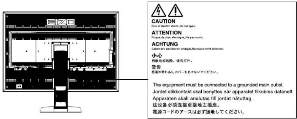
| Symbol This symbol indicates | |
| Main Power Switch: Press to turn the monitor's main power off. | |
| Main Power Switch: Press to turn the monitor's main power on. | |
| Power button: Press to turn the monitor's power on or off. | |
| Alternating current | |
| Alerting electrical hazard | |
| CAUTION: Refer to SAFETY SYMBOLS section in PRECAUTIONS. | |
No part of this manual may be reproduced, stored in a retrieval system, or transmitted, in any form or by any means, electronic, mechanical, or otherwise, without the prior written permission of EIZO Corporation.
EIZO Corporation is under no obligation to hold any submitted material or information confidential unless prior arrangements are made pursuant to EIZO Corporation's receipt of said information. Although every effort has been made to ensure that this manual provides up-to-date information, please note that EIZO monitor specifications are subject to change without notice.
Package Contents
Check that all the following items are included in the packaging box. If any items are missing or damaged, contact your local EIZO representative.
Note
- Please keep the packaging box and materials for future movement or transport of the monitor.
- Monitor
- Power cord

- Digital signal cable : DisplayPort - DisplayPort (PP300)
- Digital signal cable : DVI-D - DVI-D (Dual Link) (DD300DL)
- USB cable : UU300
• EIZO LCD Utility Disk (CD-ROM)
• Setup Manual (this manual)
- PRECAUTIONS
• VESA Mounting Screws: M4 × 12: 2 pcs.
Controls and Functions


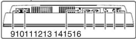

| 1. Presence Sensor | Detects the movement of a person in front of the monitor. |
| 2. MODE button | Switches the CAL Switch mode. |
| 3. RETURN button | Cancels the setting/adjustment and exits the Adjustment menu. |
| 4. ▲▼ button | Chooses and increases/decreases adjustment settings for advanced adjustment using the Adjustment menu. |
| 5. ENTER button | Displays the Adjustment menu, determines an item on the menu screen, and saves values adjusted. |
| 6. ⏻ button | Turns the power on or off Indicates the monitor's operation status.Green: Operating, Orange: Power saving mode, Off: Main power/power off |
| 7. Ambient Light Sensor | Measures the environmental illuminance. |
| 8. Integrated Front Sensor (slide type) | Used for calibration and Grayscale Check. |
| 9. Main power switch | Turns the main power on or off. |
| 10. Power connector | Connects the power cord. |
| 11. PS/2 connector | Used for maintenance. Do not use for other applications. This may cause the monitor to malfunction. |
| 12. Input signal connector | DVI-D connector (DVI-2 : Single Link) |
| 13. Input signal connector | DVI-D connector (DVI-1 : Dual Link) |
| 14. Input signal connector | DisplayPort connector |
| 15. USB upstream port | Connects the USB cable to use the software that needs USB connection, or to use USB Hub function. |
| 16. USB downstream port | Connects a peripheral USB device. |
| 17. Security lock slot | Complies with Kensington's MicroSaver security system. |
| 18. ⏻ mark | Protective earth terminal |
| 19. Stand | Used to adjust the height and angle of the monitor screen. |
| 20. Cable holder | Covers the monitor cables. |
*1 For instructions for use, refer to the User's Manual (on the CD-ROM).
Connecting Cables
Attention
- Check that the monitor and the PC are powered off.
- When replacing the current monitor with this monitor, be sure to change the PC settings for resolution and vertical scan frequency to those that are available for this monitor. Refer to the compatible resolution table (back of cover page) before connecting the PC.
Note
- When connecting multiple PCs to this product, or displaying the images from two signals at the same time using one PC, refer to the User's Manual (on the CD-ROM).
- When two signals are displayed at the same time using the "PinP" or "PbyP" functions, the following input signals are displayed on the "Main" and "Sub" screens. For details, refer to the User's Manual (on the CD-ROM).
- Main: DisplayPort or DVI-1
- Sub: DVI-2
1. Connect the signal cables to the input signal connectors and PC.
Check the shape of the connectors, and connect the cables.
After connecting the signal cable, tighten the screws of the connectors to secure the coupling.

flowchart
graph LR
    A["DisplayPort"] -->|Signal cable: DisplayPort - DisplayPort (supplied)| B["DisplayPort"]
    C["DVI-1"] -->|Signal cable: DisplayPort - DisplayPort (supplied)| B
    D["DVI-2"] -->|Signal cable: Digital connection (DVI) or Signal cable: DVI-D - DVI-D(Dual Link) (supplied)| E["DVI"]
    F["DisplayPort"] -->|Signal cable: DVI-D - DVI-D(Single Link) (option)| G["DVI"]
    H["DisplayPort"] -->|Signal cable: DVI-D - DVI-D(Supplied)] --> I["DVI"]
    J["DisplayPort"] -->|Signal cable: Digital connection (DVI) or Signal cable: Digital connection (Supplied)] --> K["DVI"]
- Plug the power cord into a power outlet and the power connector on the monitor.
- Connect the USB cable when using RadiCS LE or ScreenManager Pro for Medical.
Connecting to the Monitor Connecting to a Computer

- Press Ⓛ to turn on the monitor.
The monitor's power indicator lights up green.
- Turn on the PC.
The screen image appears.
If an image does not appear, refer to "No picture" (page 6) for additional advice.
Attention
- Turn off the monitor and PC after using them.
- For the maximum power saving, it is recommended that the Power button be turned off. Turning off the main power switch or unplugging the power cord completely shuts off power supply to the monitor.
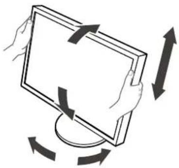
Adjusting the Screen Height and Angle
Hold left and right edge of the monitor with both hands, and adjust the screen height, tilt and swivel of the screen to the best condition for working.
natural_image
Illustration of hands holding a computer monitor with arrows indicating rotation or movement (no text or symbols)Attention
- Be sure that the cables are correctly connected.
Showing Button Guide
Press the front buttons (except Button), the Button Guide appears above the button.

Note
- The Button Guide will continue to appear while the Adjustment menu or mode menu is showing.
- The Button Guide is displayed differently depending on the selected menu or status.
Selecting Display Mode
This function allows easy selection of a desired mode according to monitor application.
√: Calibration is available.
| Mode Purpose | ||
| 1-DICOM Available to display | in DICOM mode. √ | |
| 2-Custom Available for the setting according to your preference. √ | ||
| 3-CAL1/4-CAL2/5-CAL3 Displays the screen adjusted by calibration software. √ | ||
| 6-Hybrid-γ Automatically identifies the display area for the monochrome and color images on the same screen, and displays each set status. | - | |
| 7-sRGB Suitable for color matching with sRGB compatible peripherals. - | ||
| 8-Text Suitable for displaying texts for word processing or spreadsheets. - | ||
| 9-ALT*1 | Suitable for displaying the color with the brightness and grayscale appropriate for the environmental illumination. | - |
*1 The items described above may not be displayed correctly depending on the usage environment. The quality of the monitor cannot be managed using this mode.
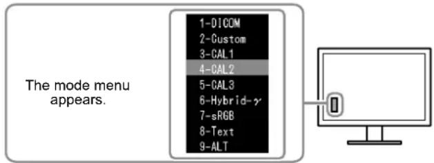
Procedure
- Press MODE.
The mode menu appears at the bottom left of the screen.
- The mode among the list is highlighted in turn each time MODES.
You can switch the mode with ▲ or ▼ while the mode menu is displayed.
1-DICOM←→2-Custom←→3-CAL1←→4-CAL2←→5-CAL3←→6-Hybrid-γ←→7-sRGB←→8-Text←→9-ALT←
Controlling Monitor Quality
The quality control software “RadiCS LE” (for Windows) is included with this monitor.
To calibrate the monitor and manage the calibration history, install RadiCS LE with reference to the RadiCS LE User's Manual (on the CD-ROM). Use the RadiCS SelfQC function and built-in Integrated Front Sensor to perform periodic calibration and Grayscale Check for the monitor independently. For details, refer to the User's Manual (on the CD-ROM).
Attention
- Connect the monitor to the PC with a USB cable when using RadiCS LE.
- To perform advanced quality control that conforms to medical standards, use the optional monitor quality control software kit “RadiCS UX1”.
Note
No picture
If a problem still remains after applying the suggested remedies, contact your local EIZO representative.
| Problem Possible cause and remedy | |
| 1. No picturePower indicator does not light. | Check whether the power cord is connected properly.Turn the main power switch on.PressTurn off the main power, and then turn it on again a few minutes later. |
| Power indicator is lighting green.Increase "Brightness", "Contrast", or "Gain" in the Adjustment menu. | |
| Power indicator is lighting orange.Switch the input signal. For details, refer to the User's Manual (on the CD-ROM).Operate the mouse or keyboard.Check whether the PC is turned on.When Presence Sensor is set to "Auto" or "Manual", the monitor may have shifted to the power saving mode.Come near to the monitor. | |
| Power indicator flashes orange and green. | There is a problem in the device that uses DisplayPort connection. Solve the problem, turn off the monitor, and then turn it on again. Refer to the user's manual of the device that uses DisplayPort connection for details. |
| 2. The message below appears. This message appears when the signal is not input correctly even when the monitor functions properly. | |
This message appears when no signal is input.Example: | The message shown left may appear, because some PCs do not output the signal soon after power-on.Check whether the PC is turned on.Check whether the signal cable is connected properly.Switch the input signal. For details, refer to the User's Manual (on the CD-ROM). |
The message shows that the input signal is out of the specified frequency range.Example: fD: Dot ClockfH: Horizontal Scan FrequencyfV: Vertical scan frequency fD: Dot ClockfH: Horizontal Scan FrequencyfV: Vertical scan frequency | Check whether the PC is configured to meet the resolution and vertical scan frequency requirements of the monitor (see "Compatible Resolutions").Reboot the PC.Select an appropriate display mode using the graphics board's utility. Refer to the manual of the graphics board for details. |
RadiForce® RX440
LCD-Farbmonitor
natural_image
Illustration of hands holding a rectangular board with arrows indicating rotation or movement (no text or symbols)Beachte
1-DICOM←→2-Custom←→3-CAL1←→4-CAL2←→5-CAL3←→6-Hybrid-γ←→7-sRGB←→8-Text←→9-ALT←
natural_image
Illustration of hands holding a computer monitor with arrows indicating rotation (no text or symbols)Attention
→ 1-DICOM←→2-Custom←→3-CAL1←→4-CAL2←→5-CAL3←→6-Hybrid-γ←→7-sRGB←→8-Text←→9-ALT←
natural_image
Illustration of hands holding a rectangular device with arrows indicating rotation or movement (no text or symbols)注意
- 请确认各接线是否正确。
显示按钮指南
→ 1-DICOM←→2-Custom←→3-CAL1←→4-CAL2←→5-CAL3←→6-Hybrid-γ←→7-sRGB←→8-Text←→9-ALT←
控制显示器质量
- Instructions for Use: ■ Setup Manual
- Compatible Resolutions
- Package Contents
- Note
- Controls and Functions
- Connecting Cables
- Attention
- Connect the signal cables to the input signal connectors and PC.
- Adjusting the Screen Height and Angle
- Showing Button Guide
- Selecting Display Mode
- Procedure
- Controlling Monitor Quality
- No picture
- RadiForce® RX440
- Beachte
- 注意
- 显示按钮指南
- 控制显示器质量
Brand : EIZO
Model : RX440-BK
Category : Monitor