
POWX0910 - Router PowerPlus - Free user manual and instructions
Find the device manual for free POWX0910 PowerPlus in PDF.


| Product type | Router |
| Brand | PowerPlus |
| Model | POWX0910 |
| Rated power | 1200 W |
| Supply voltage | 230 V ~ 50 Hz |
| No-load speed | 10,000 - 25,000 rpm |
| Collet chuck | 6 mm and 8 mm (interchangeable) |
| Max. cutting depth | 50 mm |
| Plunge stroke | 0 - 50 mm |
| Dimensions (L x W x H) | 300 x 180 x 280 mm |
| Weight | 4.2 kg |
| Sound level (LpA) | 90 dB(A) |
| Vibration level | 5.0 m/s² |
| Protection class | II (double insulation) |
| Main features | Variable speed, soft start, spindle lock, parallel guide included |
| Maintenance and cleaning | Clean ventilation slots with a dry brush; check carbon brushes regularly |
| Safety | Use safety goggles and a dust mask; do not wear loose clothing |
| Spare parts and repairability | Motor brushes, collet chuck, bearings: available from PowerPlus after-sales service |
| General information | Manual downloadable as PDF from the manufacturer's website; repairability index not communicated |
Frequently Asked Questions - POWX0910 PowerPlus
User questions about POWX0910 PowerPlus
0 question about this device. Answer the ones you know or ask your own.
Ask a new question about this device
Download the instructions for your Router in PDF format for free! Find your manual POWX0910 - PowerPlus and take your electronic device back in hand. On this page are published all the documents necessary for the use of your device. POWX0910 by PowerPlus.
USER MANUAL POWX0910 PowerPlus
natural_image
Yellow and black power plant power tool with visible circuitry and metal base (no text or symbols on main body)
NL NEDERLANDS VERTAALDE VERSIE VAN DE ORIGINELE HANDLEIDING
FR FRANÇAIS TRADUCTION DU MODE D'EMPLOI D'ORIGINE
EN ENGLISH ORIGINAL INSTRUCTION MANUAL
natural_image
Close-up of a mechanical testing setup with a cylindrical component and clamping mechanism (no visible text or symbols)
natural_image
Close-up of a gloved hand using a sewing machine to press or install a small object (no visible text or symbols)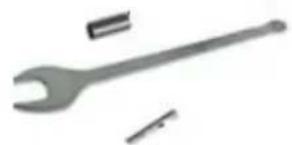
natural_image
Gray wrench and screwdriver tool (no text or symbols)
Fig 2

natural_image
Yellow and black power drill press machine with visible circuit board and base mount (no text or symbols)
natural_image
Yellow and black power expander with mechanical components, no visible text or symbolsFig 3

Fig 4

Fig 5

Fig 6

natural_image
Close-up of a hand using a microscope to adjust a small mechanical component, with no visible text or symbols.Fig 7

natural_image
Close-up of a yellow and black industrial machine component with labeled parts (no text or symbols visible)Fig 9
Fig 8
natural_image
Pure schematic diagram of a U-shaped pipe with directional arrows indicating flow or movement (no text or symbols)Fig 10
1 TOEPASSING 3
2 BESCHRIJVING (FIG. A)....3
3 INHOUD VAN DE VERPAKKING....3
4 TOELICHTING VAN DE SYMBOLEN 3
5 ALGEMENE VEILIGHEIDSVOORSCHRIFTEN ....4
5.1 Werkplaats 4
5.2 Elektrische veiligheid....4
5.3 Veiligheid van personen....4
5.4 Zorgvuldige omgang met en gebruik van elektrisch gereedschap ....5
5.5 Service....5
6 GEREEDSCHAPSPECIFIEKE VEILIGHEIDSVOORSCHRIFTEN 5
2 BESCHRIJVING (FIG. A)
20/01/2021, Lier - Belgium
20/01/2021, Lier - Belgium
1 APPLICATION ....3
2 DESCRIPTION (FIG A) 3
3 PACKAGE CONTENT LIST....3
4 SYMBOLS 3
5 GENERAL POWER TOOL SAFETY WARNINGS....4
5.1 Working area....4
5.2 Electrical safety 4
5.3 Personal safety 4
5.4 Power tool use and care....5
5.5 Service....5
6 MACHINE-SPECIFIC SAFETY WARNINGS....5
7 ASSEMBLY 6
7.1 Inserting and removing a cutter (Fig. 1)....6
7.1.1 Inserting a cutter....6
7.1.2 Removing a cutter....6
7.2 Depth adjustment (Fig. 2)....7
7.3 Locking lever (13) for cutting machine body 7
7.4 Mounting and adjusting the parallel guide (Fig. 4)....7
7.5 Fitting the centre point (Fig. 5)....7
7.6 Dust extraction outlet (Fig. 6)....7
7.7 Using the dust exhaust connection....8
8 OPERATION....8
8.1 Cutting in several operations (Fig. 7)....8
8.2 Switching on and off (Fig. 8-9)....8
8.3 Cutting direction....8
9 CLEANING, MAINTENANCE, AND LUBRICATION ....9
10 TECHNICAL DETAILS....9
11 NOISE....9
12 WARRANTY....10
13 ENVIRONMENT 10
ROUTER 1200W
POWX0910
1 APPLICATION
The router is suited for routing work to wood and wood-like materials as well as plastics. It is not designed for commercial use.

WARNING! Read this manual and general safety instructions carefully before using the appliance, for your own safety. Your power tool should only be passed on together with these instructions.
2 DESCRIPTION (FIG A)
- Handle (left and right)
- Speed control dial
- Scale label
- Depth stop
- Spindle lock button
- Collet nut
- Lock knob for parallel guide
-
Base plate
-
Length-stop turret
- Locking bolt for depth stop
- ON/OFF switch trigger
- Lock-off button
- Locking lever
- Dust extraction outlet
- Motor cover
3 PACKAGE CONTENT LIST
- Remove all packaging materials.
- Remove remaining packing and package inserts (if included).
- Check that the package contents are complete.
- Check the appliance, the power cord, the power plug and all accessories for transportation damage.
- Keep the packing materials as far as possible till the end of the warranty period. Dispose it into your local waste disposal system afterwards.

WARNING: Packaging materials are not toys! Children must not play with plastic bags! Danger of suffocation!
1 x Router
6 x ∅8mm bits
1 collet ∅8mm
1 collet ∅6mm
1 x parallel guide fence
1 x spanner key
1 x dust collection adaptor
1 x Manual

If any parts are missing or damaged, please contact your dealer.
4 SYMBOLS
In this manual and/or on the machine the following symbols are used:
 | Denotes risk of personal injury or damage to the tool. |  | Wear gloves |
 | Read manual before use |  | Wear eye protection |

In accordance with essential requirements of the European directive(s)

"Class II - The machine is double insulated; Earthing wire is therefore not necessary
5 GENERAL POWER TOOL SAFETY WARNINGS
Read all safety warnings and instructions. Failure to heed warnings and follow instructions may result in electric shock, fire and/or serious injury. Keep safety warnings and instructions for future reference. The term "power tool" in the safety warnings refers to your mains-operated (corded) power tool or battery-operated (cordless) power tool.
5.1 Working area
- Keep working area clean and well lit. Untidy and dark areas can lead to accidents.
- Do not operate power tools in potentially explosive surroundings, for example, in the presence of inflammable liquids, gases or dust. Power tools create sparks which may ignite the dust or fumes.
- Keep children and bystanders at a distance when operating a power tool. Distractions can cause you to lose control of it.
5.2 Electrical safety
- Always check that the power supply corresponds to the voltage on the rating plate.
- Power tool plugs must match the outlet. Never modify the plug in any way. Do not use adapter plugs with earthed power tools. Unmodified plugs and matching outlets will reduce the risk of an electric shock.
- Avoid body contact with earthed surfaces such as pipes, radiators, kitchen ranges and refrigerators. There is an increased risk of an electric shock if your body is earthed.
- Do not expose power tools to rain or wet conditions. If water gets inside a power tool, it will increase the risk of an electric shock.
- Do not damage the cord. Never use the cord for carrying, pulling or unplugging the power tool. Keep the cord away from heat, oil, sharp edges or moving parts. Damaged or entangled cords increase the risk of an electric shock.
- When operating a power tool outdoors, use an extension cable suitable for outdoor use. Using a cord suitable for outdoor use reduces the risk of an electric shock.
- If operating a power tool in a damp location is unavoidable, use a power supply protected by a residual current device (RCD). Using an RCD reduces the risk of an electric shock.
5.3 Personal safety
- Stay alert, watch what you are doing and use common sense when operating a power tool. Do not use a power tool when you are tired or under the influence of drugs, alcohol or medication. A moment of inattention when operating a power tool may result in serious personal injury.
- Use safety equipment. Always wear eye protection. Using safety equipment such as a dust mask, non-skid safety shoes, a hard hat, or hearing protection whenever it is needed will reduce the risk of personal injury.
- Avoid accidental starts. Ensure the switch is in the off position before inserting the plug. Carrying power tools with your finger on the switch or plugging in power tools when the switch is in the on position makes accidents more likely.
- Remove any adjusting keys or spanners before turning on the power tool. A spanner or key left attached to a rotating part of the power tool may result in personal injury.
- Do not reach out too far. Keep your feet firmly on the ground at all times. This will enable you retain control over the power tool in unexpected situations.
- Dress properly. Do not wear loose clothing or jewellery. Keep your hair, clothing and gloves away from the power tool. Loose clothes, jewellery or long hair can become entangled in the moving parts.
- If there are devices for connecting dust extraction and collection facilities, please ensure that they are attached and used correctly. Using such devices can reduce dust-related hazards.
5.4 Power tool use and care
- Do not expect the power tool to do more than it can. Use the correct power tool for what you want to do. A power tool will achieve better results and be safer if used in the context for which it was designed.
- Do not use the power tool if the switch cannot turn it on and off. A power tool with a broken switch is dangerous and must be repaired.
- Disconnect the plug from the power source before making adjustments, changing accessories, or storing power tools. Such preventive safety measures reduce the risk of starting the power tool accidentally.
- Store power tools, when not in use, out of the reach of children and do not allow people who are not familiar with the power tool or these instructions to operate it. Power tools are potentially dangerous in the hands of untrained users.
- Maintain power tools. Check for misalignment or jammed moving parts, breakages or any other feature that might affect the operation of the power tool. If it is damaged, the power tool must be repaired. Many accidents are caused by using poorly maintained power tools.
- Keep cutting tools sharp and clean. Properly maintained cutting tools with sharp cutting edges are less likely to jam and are easier to control.
- Use the power tool, accessories and cutting tools, etc., in accordance with these instructions and in the manner intended for the particular type of power tool, taking into account the working conditions and the work which needs to be done. Using a power tool in ways for which it was not intended can lead to potentially hazardous situations.
5.5 Service
- Your power tool should be serviced by a qualified specialist using only standard spare parts. This will ensure that it meets the required safety standards.
6 MACHINE-SPECIFIC SAFETY WARNINGS
- Hold tool by insulated gripping surfaces when performing an operation where the cutting tool may contact hidden wiring or its own cord. Contact with a "live" should shock the operator. If cutting into existing walls or other blind areas where electrical wiring may exist is unavoidable, disconnect all fuses or circuit breakers feeding this worksite.
- Always make sure the work surface is free from nails and other foreign objects. Cutting into a nail can cause the bit and the tool to jump and damage the bit.
- Never hold the workpiece in one hand and the tool in the other hand when in use. Never place hands near or below cutting surface. Clamping the material and guiding the tool with both hands is safer.
- Never lay workpiece on top of hard surfaces, like concrete, stone, ect... protruding cutting bit may cause tool to jump.
- Always wear safety goggles and dust mask. Use only in well ventilated area. Using personal safety devices and working in safe environment reduces risk of injury.
■ After changing the bit or making any adjustments, make sure the collet nut and any other adjustment devices are securely tightened. Loose adjustment device can unexpectedly shift, causing loss of control; loss-rotating components will be violently thrown.
- Never start the tool when the bit is engaged in the material. The bit cutting edge may grab the material causing loss of control of the cutter.
- Always hold the tool with two hands during start-up. The reaction torque of the motor can cause the tool to twist.
- The direction of feeding the bit into the material is very important and it relates to the direction of bit rotation. When viewing the tool form the top, the bit rotates clockwise. Feed direction of cutting must be counter-clockwise (Fig 12). NOTE: inside and outside cuts will require different feed direction; refer to section on feeding the router. Feeding the tool in the wrong direction causes the cutting edge of the bit to climb out of the work and pull the tool in the direction of this feed.
- Never use dull or damaged bits. Sharp bits must be handled with care. Damaged bits can snap during use. Dull bits require more force to push the tool, possibly causing the bit to break.
- Never touch the bit during or immediately after the use. After use the bit is too hot to be touched by bare hands.
- Never lay the tool down until the motor has come to a complete standstill. The spinning bit can grab the surface and pull the tool out of your control.
- Never use bits that have a cutting diameter greater than the opening in the base.

WARNING: Some dust created by power sanding, sawing, grinding, drilling, and other construction activities contains chemicals known to cause cancer, birth defects or other reproductive harm. Some examples of these chemicals are:
- Lead form lead-based paints,
– Crystalline silica form bricks and cement and other masonry products, and - Arsenic and chromium form chemically treated lumber.
Your risk form these exposures vary, depending on how often you do this type of work. To reduce you exposure to these chemicals: work in a well ventilated area, and work with approved safety equipment, such as those dust masks that are specially designed to filter out microscopic particles.
7 ASSEMBLY
7.1 Inserting and removing a cutter (Fig. 1)
7.1.1 Inserting a cutter
- Press and hold down the spindle lock button (5).
- Using the wrench to loosen the collet nut (6) a few turns, insert a collet and a cutter into order.
- Tighten the collet nut and release the spindle lock button.
7.1.2 Removing a cutter
- Press and hold down the spindle lock button (5) and loosen the collet nut (6) completely.
■ Remove the cutter. - Fit a new suitable accessory and tighten the collet nut.

Note: Never tighten the collet nut without a cutter in the collet.
7.2 Depth adjustment (Fig. 2)
Locate the depth stop (4) on the left-hand side of the cutting machine. This continuously adjustable stop is intended to limit the depth of the cut. Loosen it by turning it in anticlockwise direction. To move the depth stop up or down to the desired depth according to the marker of the scale label (3).

NOTE: Make sure the locking knob (10) is fixed firmly when operating this machine.
7.3 Locking lever (13) for cutting machine body
When viewed from the front, the locking lever is located at the rear on the left-hand side. The cutting machine body is spring-tensioned. Take care when releasing the locking lever. Grasp both handles and brace yourself before releasing the lever. Press downwards to allow the cutting machine body to move down. When you reduce the downward pressure, the springs force the cutting machine body back up into its highest position.
The released position (a) or lock position (b) of locking lever as shown in Fig. 3.

CAUTION: The housing of the machine is under spring tension. When you release the locking lever, it returns to its highest position.
7.4 Mounting and adjusting the parallel guide (Fig. 4)
- The parallel guide can be used for cutting parallel to the edge of the work-piece.
■ Fit the guide rods (a) to the frame using the screws (b). - Release the two lock knobs securing the parallel guide and push them in so that the guide is at the desired distance from the cutter head.
- Tighten the two lock knobs.
- Press the guide securely against the edge of the work-piece and execute the cut.

CAUTION: Abnormal vibrations may be due to a blunt cutter head.
7.5 Fitting the centre point (Fig. 5)
The centre point is used for routing circles.
- Remove a guide rod (a) from the parallel guide.
- Mount the centre point (b) to the guide rod.
- Slide the guide rod in the router base plate and tighten the lock knobs.
- Position the tip of centre point at the centre of your circle.
- Press it slightly so that the tip is firmly in the wood. You can now cut the circle.
7.6 Dust extraction outlet (Fig. 6)
It is advised to use the dust extraction outlet. You can purchase a suitable commercial vacuum cleaner or extract the dust via an extractor tube while the cutting machine is in operation. The outlet must project out of the rear of the machine. Two bolts and nuts are supplied to attach it.
- Hold the dust extraction outlet (14) in position and lay the cutting machine on its side.
- Push the screw through the hole of the template guide (a), dust extraction outlet (14) and router's base plate (8) and until it projects at the fastening point for the dust extraction outlet.
- Tighten the screw with a suitable screwdriver and moderate force until the outlet is securely attached.
- Repeat the procedure at the other side.

CAUTION: Dust may cause respiratory problems. Certain laminated board materials are carcinogenic. After work, always remove all dust from the machine.
7.7 Using the dust exhaust connection
- The dust exhaustion outlet (14) shall be connecting together with an external vacuum cleaner to take away the dust in dust cover.
■ If necessary, place an adapter on the dust exhaust.
8 OPERATION
8.1 Cutting in several operations (Fig. 7)
The length-stop turret (9) can be used to set different depths.
For cutting in depth and in stages, use the length-stop turret (9) as an aid. Using the depth stop set the desired depth to the lowest depth-stop position on the turret. Rotate the turret so that the highest point is under the depth stop and execute the first cut. Repeat the cut with the second-highest setting and finally with the last setting. You can also use two positions if the desired depth is reached in two operations.
8.2 Switching on and off (Fig. 8-9)
- Connect the plug to the power supply.
- To switching the tool on, keep the lock-off button (12) depressed and press the ON/OFF switch trigger (11).
■ To switching the tool off, release the ON/OFF switch trigger (11).
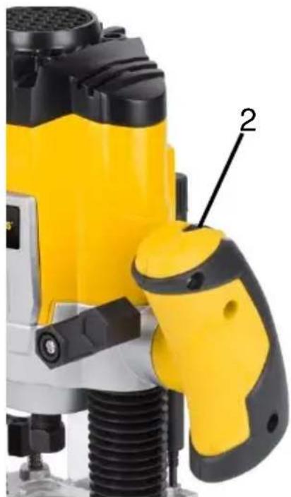
- To adjust the cutting speed, turn the speed control dial (2). Position "1" denotes the lowest speed. Position "7" denotes the highest speed. Turn the knob to increase or decrease the speed. The smaller the cutter head, the higher the speed. The larger the cutter head, the lower the speed. A cutter head which runs too fast causes scorching of the work-piece and leaves burnt marks.

CAUTION: Do not change the speed when the machine is working under load.
8.3 Cutting direction
■ Always observe the safety instructions and applicable regulations.
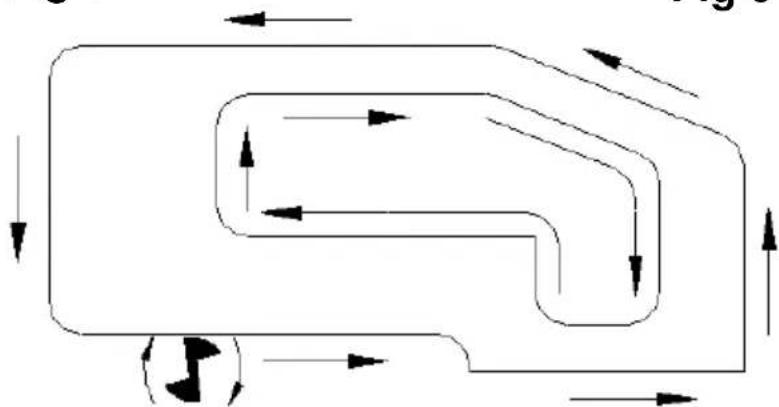
■ Always move your router as indicated in below Fig. 10 (outer edges/inner edges).
- To prevent the cutter head from jumping and to obtain a good result, carry out exterior cuts in anticlockwise and interior cuts in clockwise direction.

NOTE: Check that the cutter is correctly installed in the collet.
- Place the machine on the workpiece before switching on.
- Select the optimal speed using the speed control dial.
- Set the cutting depth.
■ For greater cutting depths it is recommended to make shallow cuts.
■ Connect a dust cover.
■ Make sure the locking lever is always locked before switching on.
9 CLEANING, MAINTENANCE, AND LUBRICATION
■ Before each use, inspect the general condition of the tool. Check for loose hardware, misalignment or binding of moving parts, cracked or broken parts, damaged electrical wiring, and any other condition that may affect its safe operation.
■ After Use, wipe external surfaces of the tool with clean cloth.
- Periodically blow out the motor vent holes with compressed air to prevent the buildup of dust and particles.
Periodically wipe the collet, collet cones, and cutting bits with a light oil to prevent rust.
- Over time, if the performance of the tool diminishes, or it stops working completely, it may be necessary to replace the carbon brushes by removing the brush holder cap. This procedure must be completed by a qualified technician.

WARNING! If the supply cord of this power tool is damaged, it must be replaced only by a qualified service technician.
10 TECHNICAL DETAILS
| Model nr. | POWX0910 |
| Voltage | 230V |
| Mains frequency | 50 Hz |
| Power | 1200W |
| No load speed | 11 000-30 000 min-1 |
| Cutting depth | 35 mm |
| Spindle diameter cutter | 6/8 mm |
11 NOISE
| Noise emission values measured according to relevant standard. (K=3) | |
| Acoustic pressure level LpA | 88 dB(A) |
| Acoustic power level LwA | 99 dB(A) |

ATTENTION! Wear hearing protection when sound pressure is over 85 dB(A).
aw (Vibration)
7.1 m/s²
K = 1,5 ~m / s^2
12 WARRANTY
- This product is warranted for a 36-month period effective from the date of purchase by the first user.
- This warranty covers all material or production flaws excluding : batteries, chargers, defective parts subject to normal wear & tear such as bearings, brushes, cables, and plugs, or accessories such as drills, drill bits, saw blades, etc. ; damage or defects resulting from maltreatment, accidents or alterations; nor the cost of transportation.
- Damage and/or defects resulting from inappropriate use also do not fall under the warranty provisions.
- We also disclaim all liability for any bodily injury resulting from inappropriate use of the tool.
- Repairs may only be carried out by an authorised customer service centre for Powerplus tools.
- You can always obtain more information at the number 00 32 3 292 92 90.
- Any transportation costs shall always be borne by the customer, unless agreed otherwise in writing.
- At the same time, no claim can be made on the warranty if the damage of the device is the result of negligent maintenance or overload.
- Definitely excluded from the warranty is damage resulting from fluid permeation, excessive dust penetration, intentional damage (on purpose or by gross carelessness), inappropriate usage (use for purposes for which the device is not suitable), incompetent usage (e.g. not following the instructions given in the manual), inexpert assembly, lightning strike, erroneous net voltage. This list is not exhaustive.
- Acceptance of claims under warranty can never lead to the prolongation of the warranty period nor commencement of a new warranty period in case of a device replacement.
- Devices or parts which are replaced under the warranty therefore remain the property of Varo NV.
- We reserve the right to reject a claim whenever the purchase cannot be verified or when it is clear that the product has not been properly maintained. (Clean ventilation slots, carbon brushes serviced regularly, etc.).
- Your purchase receipt must be kept as proof of date of purchase.
- Your appliance must be returned undismantled to your dealer in an acceptably clean state, (in its original blow-moulded case if applicable to the unit), accompanied by proof of purchase.
13 ENVIRONMENT

Should your appliance need replacement after extended use, do not dispose of it with the household refuse, but in an environmentally safe way.
Waste produced by electrical machine items should not be handled like normal household rubbish. Please recycle where recycle facilities exist. Check with your Local Authority or retailer for recycling advice.
14 DECLARATION OF CONFORMITY


VARO N.V. -- Vic. Van Rompuy N.V. - Joseph Van Instraat 9 - BE2500 Lier - BELGIUM, declares that,
Product: Router
Trade mark: POWERplus
Model: POWX0910
is in conformity with the essential requirements and other relevant provisions of the applicable European Directives, based on the application of European harmonized standards. Any unauthorized modification of the apparatus voids this declaration.
European Directives (including, if applicable, their amendments up to the date of signature); 2011/65/EU 2006/42/EC 2014/30/EU
European harmonized standards (including, if applicable, their amendments up to the date of signature);
EN62841-1:2015
EN62841-2-17:2017
EN55014-1:2017
EN55014-2:2015
EN61000-3-2:2014
EN61000-3-3:2013
Keeper of the Technical Documentation : Philippe Vankerkhove, VARO – Vic. Van Rompuy N.V.
The undersigned acts on behalf of the company CEO,
Philippe Vankerkhove
Regulatory Affairs – Compliance Manager
20/01/2021, Lier - Belgium
1 EINSATZBEREICH 3
OBERFRÄSE 1200W POWX0910
1 EINSATZBEREICH
20/01/2021, Lier - Belgium
Regulatory Affairs – Compliance Manager
20/01/2021, Lier - Belgium
1 APLICACÃO....3
WARNING: Some dust created by power sanding, sawing, grinding, drilling, and other construction activities contains chemicals known to cause cancer, birth defects or other reproductive harm. Some examples of these chemicals are:
- Lead form lead-based paints,
– Crystalline silica form bricks and cement and other masonry products, and - Arsenic and chromium form chemically treated lumber.
Your risk form these exposures vary, depending on how often you do this type of work. To reduce you exposure to these chemicals: work in a well ventilated area, and work with approved safety equipment, such as those dust masks that are specially designed to filter out microscopic particles.
7 MONTAGEM
20/01/2021, Lier - Belgium
1 BRUKSOMRÅDE....3
2 BESKRIVELSE (FIG. A) 3
3 PAKKENS INNHOLD 3
4 SYMBOLFORKLARING ....3
5 GENERELLE SIKKERHETSADVARSLER 4
5.1 Arbeidsplassen....4
5.2 Elektrisk sikkerhet....4
5.3 Personsikkerhet....4
5.4 Vær nøyaktig og omhyggelig når du omgås elektroverktøy....5
5.5 Service....5
6 MASKINAVHENGIG SIKKERHETSINFORMASJON ....5
7 MONTERING....6
7.1 Sette i og fjerne et fresestål (Fig. 1)....6
7.1.1 Sette i et fresestål....6
7.1.2 Fjerne et fresestål....6
7.2 Dybdejustering (Fig. 2)....7
7.3 Låsespak (13) for fresemaskinen....7
7.4 Montere og justere parallellanslaget (Fig. 4)....7
7.5 Montere senterpunktet (Fig. 5)....7
7.6 Kobling for støvavtrekk (Fig. 6)....7
7.7 Bruke støvavtrekk....8
8 BRUK....8
8.1 Fresing i flere trinn (Fig. 7)....8
8.2 Slå på og av (Fig. 8-9)....8
8.3 Freseretning....8
9 RENGJ∅RING, VEDLIKEHOLD OG SM∅RING....8
10 TEKNISKE DATA....9
11 ST∅Y....9
12 GARANTI....9
13 MILJ∅ 9
OVERFRES 1200W
POWX0910
1 BRUKSOMRÅDE
9 RENGJ∅RING, VEDLIKEHOLD OG SM∅RING
20/01/2021, Lier - Belgium
1 ANVENDELSE 3
2 BESKRIVELSE (FIG. A) 3
3 MEDF∅LGENDE INDHOLD 3
4 SYMBOLER....4
5 ALMINDELIGE SIKKERHEDSANVISNINGER FOR EL-VÄERKTÖJ....4
5.1 Arbejdsområde 4
5.2 Elektrisk sikkerhed....4
5.3 Personlig sikkerhed....4
Regulatory Affairs (afdelingen for juridiske anliggender) – Compliance Manager 20/01/2021, Lier - Belgium
1 ANVÄNDNINGSOMRÅDELEVER....3
2 BESKRIVNING (FIG. A)......3
3 FÖRPACKNINGSINNEHÅLL 3
4 SYMBOLER....4
5 ALLMÄNNA SÄKERHETSANVISNINGAR FÖR ELEKTRISKA VERKTYG....4
3 FÖRPACKNINGSINNEHÅLL
20/01/2021, Lier - Belgium
1 KÄYTTÖ 3
2 KUVAUS (KUVA A) 3
3 PAKKAUKSEN SISÄLTÖ....3
4 SYMBOLIT 3
5 YLEISET TURVALLISUUSOHJEET 4
10 TEKNISET TIEDOT....9
11 MELU....9
12 TAKUU....10
13 LAITTEEN KÄYTÖSTÄ POISTAMINEN 10
JYRSIN 1200W
POWX0910
1 KÄYTTÖ
20/01/2021, Lier - Belgium
1 ΕΦΑΡΜΟΓΗ....3
2 ПЕРИГРАФН (ЕИК. А)......3
20/01/2021, Lier - Belgium
1 PRIMJENA 3
2 OPIS (SL. A)....3
3 POPIS SADRŽAJA PAKETA 3
4 SIMBOLI 4
5 OPĆA UPOZORENJA O SIGURNOSTI RUKOVANJA ELEKTRIČNIM ALATIMA......4
20/01/2021, Lier - Belgium
1 PRIMENA 3
2 OPIS (SL. A)....3
3 SPISAK SADRŽAJA PAKOVANJA 3
4 SIMBOLI 4
5 OPŠTA BEZBEDNOSNA UPUTSTVA ZA ELEKTRIČNE ALATE 4
5.1 Radna oblast....4
20/01/2021, Lier - Belgium
1 OBLAST POUŽITÍ....3
2 POPIS (OBR. A)....3
3 SEZNAM OBSAHU BALENÍ....3
4 SYMBOLY 4
5 OBECNÁ BEZPEČNOSTNÍ UPOZORNĚNÍ PRO ELEKTRICKÉ NÁSTROJE 4
20/01/2021, Lier - Belgium
1 POUŽÍVANIE....3
2 POPIS (OBR. A)....3
3 OBSAH BALENIA....3
4 SYMBOLY 4
5 VŠEOBECNÉ BEZPEČNOSTNÉ VAROVANIA PRE ELEKTRICKÉ NÁRADIE ....4
5.1 Pracovná plocha....4
6 VARNOSTNA OPOZORILA ZA TO NAPRAVO....5
7 SESTAVLJANJE....7
20/01/2021, Lier - Belgium
1 DOMENII DE UTILIZARE....3
2 DESCRIERE (FIG. A)....3
3 CONTINUTUL PACHETULUI 3
4 SIMBOLURI....4
5 AVERTISMENTE GENERALE DE SIGURANTĂ PRIVIND APARATUL ELECTRIC....4
5.1 Zona de lucru 4
20/01/2021, Lier - Belgium
1 ALKALMAZÁS....3
2 LEÍRÁS (A ÁBRA) 3
3 CSOMAGOLÁS TARTALMA....3
4 JELZÉSEK 4
5 ÁLTALÁNOS BIZTONSÁGI UTASÍTÁSOK SZERSZÁMGÉPEKHEZ 4
20/01/2021, Lier - Belgium
20/01/2021, Lier - Belgium
1 ПРЕДНАЗНАЧЕНИЕ НА ЕЛЕКТРОИНСТРУМЕНТА....3
2 ОПИСАНИЕ (ФИГ. А) 3
3 СПИСЪК НА СЪДЪРЖАНИЕТО НА ОПАКОВКАТА....3
4 СИМВОЛИ 4
5 ОБЩИ ПРЕДУПРЕЖДЕНИЯ ЗА БЕЗОПАСНОСТ ПРИ ИЗПОЛЗВАНЕ НА ЕЛЕКТРОИНСТРУМЕНТИ......4
5.1 Работна зона....4
20/01/2021, Lier - Belgium
1 PIELIETOJUMS 3
2 APRAKSTS (A. ATT.) 3
3 IEPAKOJUMA SATURA SARAKSTS 3
4 APZİMĚJUMI 3
5 VISPĀRĪGI DARBARĪKA DROŠĪBAS BRĪDINĀJUMI 4
20/01/2021, Lier - Belgium
5 ÜLDISED HOIATUSED JA OHUTUSJUHISED
6 SEADMEPÕHISED HOIATUSED
20/01/2021, Lier - Belgium
natural_image
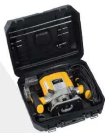
Open black and yellow plastic case containing a yellow and silver power tool (no visible text or symbols)varo
WWW.VARO.COM
DESIGNED AND MARKETED BY VARO
©copyright by varo
VARO - VIC. VAN ROMPUY nv
JOSEPH VAN INSTRAAT 9 - 2500 LIER - BELGIUM
OFFICES:

- GEREEDSCHAPSPECIFIEKE VEILIGHEIDSVOORSCHRIFTEN 5
- BESCHRIJVING (FIG. A)
- ROUTER 1200W
- POWX0910
- APPLICATION
- DESCRIPTION (FIG A)
- PACKAGE CONTENT LIST
- SYMBOLS
- GENERAL POWER TOOL SAFETY WARNINGS
- Working area
- Electrical safety
- Personal safety
- Power tool use and care
- Service
- MACHINE-SPECIFIC SAFETY WARNINGS
- ASSEMBLY
- Inserting and removing a cutter (Fig. 1)
- Inserting a cutter
- Removing a cutter
- Depth adjustment (Fig. 2)
- Locking lever (13) for cutting machine body
- Mounting and adjusting the parallel guide (Fig. 4)
- Fitting the centre point (Fig. 5)
- Dust extraction outlet (Fig. 6)
- Using the dust exhaust connection
- OPERATION
- Cutting in several operations (Fig. 7)
- Switching on and off (Fig. 8-9)
- Cutting direction
- CLEANING, MAINTENANCE, AND LUBRICATION
- TECHNICAL DETAILS
- NOISE
- WARRANTY
- ENVIRONMENT
- DECLARATION OF CONFORMITY
- OBERFRÄSE 1200W POWX0910
- EINSATZBEREICH
- MONTAGEM
- OVERFRES 1200W
- BRUKSOMRÅDE
- RENGJ∅RING, VEDLIKEHOLD OG SM∅RING
- FÖRPACKNINGSINNEHÅLL
- JYRSIN 1200W
- KÄYTTÖ
- ÜLDISED HOIATUSED JA OHUTUSJUHISED
- SEADMEPÕHISED HOIATUSED
Brand : PowerPlus
Model : POWX0910
Category : Router