
TVAC15100 - Audio/video extension ABUS - Free user manual and instructions
Find the device manual for free TVAC15100 ABUS in PDF.


| Product type | Audio/video extender |
| Brand | ABUS |
| Model | TVAC15100 |
| Category | Audio/video extender |
| Cable length | 15 meters |
| Connectors | 1x HDMI male, 1x HDMI female |
| HDMI version | HDMI 2.0 |
| Maximum resolution | 4K at 60 Hz |
| Bandwidth | 18 Gbit/s |
| Cable material | Oxygen-free copper |
| Outer sheath | PVC |
| Shielding | Triple shielding |
| Weight | 350 g |
| Color | Black |
| Power supply | Not required (passive) |
| Operating temperature | -20 °C to 60 °C |
| Compatibility | HDMI 1.4 and higher, HDCP 2.2 |
| Warranty | 2 years |
| Package contents | 1 HDMI extension cable |
| Care and cleaning | Clean with a dry, soft cloth |
| Safety | Do not bend excessively, avoid heat sources |
Frequently Asked Questions - TVAC15100 ABUS
User questions about TVAC15100 ABUS
0 question about this device. Answer the ones you know or ask your own.
Ask a new question about this device
Download the instructions for your Audio/video extension in PDF format for free! Find your manual TVAC15100 - ABUS and take your electronic device back in hand. On this page are published all the documents necessary for the use of your device. TVAC15100 by ABUS.
USER MANUAL TVAC15100 ABUS
natural_image
Two black ARUS wireless devices with visible antennas and ports, no text or symbols on the device surfaces.These user manual contains important information for installation and operation. This should be also noted when this product is passed on to a third party. Therefore look after these operating instructions for future reference!
A list of contents with the corresponding page number can be found in the index on page 15.
Français
natural_image
Two black ASUS-branded wireless devices with visible antennas and signal waves (no text or symbols on the devices themselves)Bedienungsanleitung
Version 06/2011
CE
natural_image
Pure electrical connector diagram showing three connected ports (no text or symbols)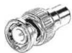
AV-Kabel 2x BNC-RCA Adapter
| 1 | Masse | Gemeinsame | Masse |
| 2 | Audio Kanal 1 Audiosignal | ||
| 3 | Videosignal | Videosignal | |
| 4 | Audio Kanal 2 Audiosignal |
natural_image
Two black ASUS-branded wireless devices with visible antennas and ports (no text or symbols on the devices themselves)User manual
Version 06/2011
CE
Original English user manual. Keep for future use.
Introduction
Dear Customer,
Thank you for purchasing this product.
This product meets the requirements of the applicable European and national guidelines. The corresponding declarations and documents can be obtained from the manufacturer (www.abus-sc.com).
To maintain this condition and to ensure risk-free operation, you as the user must observe these operation instructions!
Before initial start-up, read through the complete operating instructions observing operating and safety instructions.
All company and product names mentioned in this document are registered trademarks. All rights reserved.
If you have any questions, please contact your installer or your local dealer!

Disclaimer
This user manual was prepared with greatest care. If you should notice omissions or inaccuracies, please inform us about these on the back of this manual given address.
The ABUS Security-Center GmbH assumes no liability for technical and typographical faults and reserves the right to make at any time modifications to the product or user manual without a previous announcement.
The company is not liable or responsible for direct and indirect subsequent damages which are caused in connection with the equipment, the performance and the use of this product.
No guarantee for the content of this document is taken.
Icon explanation
 | A flash in the triangle is used if there is danger for the health, e.g. by an electric shock. |
 | An exclamation mark in the triangle points to an important note in this user manual which must be minded. |
 | This symbol can be found when you are to be given tips and information on operation. |
Important safety advice
 | The warranty will expire for damage due to non-compliance with these operating instructions. ABUS will not be liable for any consequential loss! |
 | ABUS will not accept liability for damage to property or personal injury caused by incorrect handling or non-compliance with the safety-instructions.In such cases the warranty will expire. |
The device has been manufactured in compliance with international safety standards. Please read these safety advices carefully.
Safety advice
- Mains supply
100–240 V AC, 50–60 Hz (via power adapter plug to 5 V DC)
Operate this product only from the type of power supply indicated on the marking label. If you are not sure of the type of power supplied to your home, consult your local power company. Disconnect the product from the mains before you start any maintenance or installation procedures.
- Overloading
Do not overload a wall outlet, extension cord or adapter as this may result in electric fire or shock.
- Liquids
Protect the device from any kind of liquids entering.
- Cleaning
Disconnect the product from the wall outlet before cleaning. Use a light damp cloth (no solvents) to dust the product.
- Accessories
Do not use any unsupported accessories as these may be hazardous or cause damage the product.
-
Location
-
Setup the device only in dry and dust-protected rooms.
- Do not place the device near a radiator or heat register.
-
Setup the device only in areas with the advised operating temperatures of -10^ 50^ .
-
Wireless transmission
The range of wireless transmission depends on various environmental factors. The local conditions at the installation location can have a negative impact on the range. For this reason, if there is a clear line of sight between the receiver and the transmitter, the range can be as much as 200 m, but in buildings it is significantly less.
The following environmental factors impair both the range and the frame rate:
Mobile phone masts, high-tension electricity pylons, power lines, ceiling and walls, devices with the same or similar radio frequency.
Warnings
Follow all safety and operating advises before starting-up the device!
-
Follow these directions in order to avoid damage of the power cord or plug:
-
Do not modify or process the power cord or plug arbitrarily.
- Make sure to disconnect the power cord holding the plug.
-
Keep heating appliances as far as possible from the power cord in order to prevent the cover vinyl from melting.
-
Follow these directions. Failure to follow any of them may cause electrical shock:
-
Do not open the main body or the power supply.
- Do not insert metal or inflammable objects inside the product.
-
In order to avoid any damage during lighting use a surge protection.
-
Do not use the product when it is out of order. If you continue to use the product when defective, serious damage can be caused to it. Make sure to contact your local product distributor if the product is out of order.
 | During the installation into an existing video surveillance system make sure that all devices are disconnected from the low and supply voltage circuit. |
 | If in doubt allow a professional electrician to mount, install and wire-up your device. Improper electrical connection to the mains does not only represent at threat to you but also to other persons.Wire-up the entire system making sure that the mains and low voltage circuit remain separated and cannot come into contact with each other in normal use or due to any malfunctioning. |
Unpacking
While you are unpacking the device please handle it with utmost care.
| If you notice any damage of the original packaging, please check at first the device.If the device shows damages, please contact your local dealer. |
Table of contents
- Intended Use.... 16
- Scope of delivery....16
- Features and functions....16
- Description of the connections....17
4.1 Rear of the transmitter 17
4.2 Rear of the receiver....17
4.3 Cable connections....18
4.4 Video/audio signals on the jack plug....18
4.5 LEDs....19
- Installation....19
5.1 Installation set-up....19
5.2 Pairing the transmitter and receiver 20
- Maintenance and cleaning....20
6.1 Maintenance....20
6.2 Cleaning 21
-
Disposal....21
-
Technical data....21
1. Intended Use
Using this 2.4 GHz digital transmission set, you can transmit video and audio signals wireless over medium to long distances without any problems. The video transmission set consists of a wireless transmitter and a wireless receiver.
Wireless signal transmission is an advantage in all locations where cables cannot be laid. The transmitter module transmits the signal recorded by the camera wirelessly to the receiver module. Faults and interference can be avoided due to the conversion into digital signals.
A detailed function description can be found in chapter 3 ("Description and functions").
2. Scope of delivery

natural_image
Line drawing of two electronic devices with ventilation slots (no text or symbols)Receiver and transmitter unit
natural_image
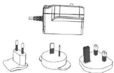
Technical line drawings of electronic components including a battery pack, two cylindrical pins, and a multi-pin base (no text or symbols)Power supply unit incl. EU, AU and UK plugs
natural_image
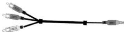
Pure electrical connector diagram showing three connected ports (no text or symbols)AV cable 2x BNC-RCA adapters
3. Features and functions
- Wireless transmission of video and audio signals
• Transmission frame rate = 30 fps @ D1 resolution
• 2.4 GHz encoded digital wireless transmission
• Integrated IR transmitter
• Digital wireless transmission for cameras and recorders
4. Description of the connections
4.1 Rear of the transmitter

| 1 | Power supply 5 V DC/1 A (DC, 14.5 x 4.8 mm) |
| 2 | AV input Input for the transmitted signal, use the AV cable supplied |
| 3 | Pairing button Button for pairing the transmitter and receiver |
| 4 | Power switch Switches the transmitter on/off |
4.2 Rear of the receiver

| 1 | Power supply 5 V DC/1 A (DC, 14.5 x 4.8 mm) |
| 2 | AV output Output for representing the transmitted signal, use the AV cable supplied |
| 3 | Pairing button Button for pairing the transmitter and receiver |
| 4 | Power switch Switches the receiver on/off |
4.3 Cable connections

| 1 | Yellow RCA connector (video) | Connection for transmitting the video signal |
| 2 | Red RCA connector (audio) | Connection for transmitting the audio signal |
| 3 | White RCA connector (audio) | Connection for transmitting the audio signal |
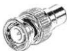
To connect the video RCA plug to a BNC input or output on a camera, monitor or recorder, attach the BNC-RCA adapter to the yellow RCA plug.
4.4 Video/audio signals on the jack plug

| 1 | Ground Common ground connection | |
| 2 | Audio channel 1 Audio signal | |
| 3 | Video signal Video signal | |
| 4 | Audio channel 2 Audio signal |
4.5 LEDs

| 1 | Power LED Device status display | |
| 2 | IR LED | Transmission/reception of an IR signal for a remote control |
| 3 | LINK LED | Connection status displayVisual contact |
| Description | LED on | LED flashing | LED off |
| Power LED | Device switched on - Device | switched off | |
| LINK LED | Connection established Connection | being made No connection | |
5. Installation
5.1 Installation set-up

flowchart
graph LR
    A["Device"] --> B["Router"]
    B --> C["Switch"]
    C --> D["Computer"]
Connect the monitor output on a recorder or video output on a camera to the transmitter. Use the supplied AV cable and the BNC-RCA adapters.
Connect the receiver to a monitor. Now connect the supplied power supply units to the receiver and transmitter, then switch them on (move switch from "0" to "I").
| Warning:Please note that the image transmission rate can be limited depending on the ambient conditions. |

flowchart
graph LR
    A["Camera"] --> B["RF"]
    B --> C["Computer"]
    C --> D["Server"]
Connect a camera to the transmitter to establish wireless transmission of the signal to a recorder or monitor via the receiver.
The IR sensor is located in the middle between the LEDs. Using the receiver, you have the possibility of transmitting the signals from a remote control to the transmitter. The transmitter then sends on the received IR signals (e.g. to a recorder).
Please ensure that the IR LED on the transmitter has a direct visual contact to the IR LED on the recorder.

Warning: Please ensure that the IR LED on the transmitter has a direct visual contact to the IR LED on the recorder for transmission.
5.2 Pairing the transmitter and receiver
Proceed as follows to pair the transmitter and receiver:
- First press the PAIRING button on the receiver until the green LINK LED on the front starts to flash.
- Now press the PAIRING button on the transmitter until the green LINK LED on the front starts to flash.
- Both LINK LEDs on the devices light up continuously when the connection has been established successfully.

Warning: Please note that connection can take up to 30 seconds.
6. Maintenance and cleaning
6.1 Maintenance
Regularly check the product's physical state, e.g. check for damage of the housing.
If you suspect that safe operation cannot be guaranteed anymore, disconnect the product and ensure that it cannot be used by mistake.
You can assume that safe operation is not possible anymore when
- the device shows visible damage,
- the device does not function anymore

Please note:
The product is maintenance free for you. Inside the product are no parts that can be checked or repaired, so do not ever open it.
6.2 Cleaning
Wipe the product with a clean, dry cloth. If the device is very dirty, you can moisten the cloth with lukewarm water.

Make sure that no liquids can enter the equipment as the device can be destroyed. Never use chemical detergents as they could attack the surface of the device
7. Disposal
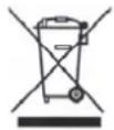
Devices with this marking should not be put in the household garbage. Dispose of the product at the end of its lifetime according to the applicable regulations.
8. Technical data
| Model number | TVAC15100Transmitter | TVAC15100Receiver |
| Frequency | 2.4 | |
| Inputs AV IN, DC input DC input | ||
| Outputs | - | AV |
| LED displays | POWER: Power supplyIR: IR signalLINK: Connection status | |
| Resolution D1 (720 x 480) | ||
| Frame rate Max. 30 fps | ||
| Transmission channels 1 | ||
| Range approx. 100 m (clear sight line)* | ||
| Power supply 5 V DC/1 A | ||
| Power consumption | Max. 400 mA | Max. 300 mA |
| Operating temperature | -10 °C – 50 °C | |
| Dimensions | 114 x 85 x 23 mm | |
| Weight | 90 g | |
* The range depends on the ambient conditions (e.g. mobile phone masts, high-tension electricity pylons, power lines, ceiling and walls, etc.).
If the conditions are unfavourable, the range may be very restricted.
TVAC15100

natural_image
Two black ASUS-branded wireless devices with visible antennas and ports (no text or symbols on the devices themselves)Manuel utilisateur
Version 06/2011
CE
natural_image
Line drawing of two electronic devices with ventilation slots (no text or symbols)natural_image
Technical line drawings of electronic components including a battery, two terminal blocks, and a base (no text or symbols)natural_image
Pure electrical connector diagram showing three connected ports (no text or symbols)natural_image
Two black ASUS-branded wireless devices with visible antennas and ports (no text or symbols on the devices themselves)natural_image
Line drawing of two electronic devices with ventilation slots (no text or symbols)natural_image
Technical line drawings of electronic components including a battery, two terminal blocks, and a multi-pin base (no text or symbols)Netadapter incl. EU-, AU-, en UK-stekkers

natural_image
Pure electrical connector diagram showing three connected ports (no text or symbols)AV-kabel

2x
BNC-RCA-adap
natural_image
Two black ASUS-branded electronic devices with visible antennas and ports (no text or symbols on the devices themselves)Brugerhåndbog
Version 06/2011
CE
natural_image
Line drawing of two electronic devices with ventilation slots (no text or symbols)natural_image
Technical line drawings of electronic components including a battery, plug, and socket (no text or symbols)natural_image
Pure electrical connector diagram showing three connected ports (no text or symbols)AV-kabel

2x
BNC-RCA-adap
| 1 | Stel | Fælles stel |
| 2 | Audiokanal 1 Audiosignal | |
| 3 | Videosignal | Videosignal |
| 4 | Audiokanal 2 Audiosignal |
These operating instructions are published by ABUS Security-Center GmbH & Co.KG, Linker Kreuthweg 5, 86444 Affing, Germany. No reproduction (including translation) is permitted in whole or part e.g. photocopy, microfilming or storage in electronic data processing equipment, without the express written consent of the publisher. The operating instructions reflect the current technical specifications at the time of print. We reserve the right to change the technical or physical specifications.
© Note de l'éditeur
© Copyright 06/2011 by ABUS Security-Center
- Bedienungsanleitung
- User manual
- Introduction
- Disclaimer
- Icon explanation
- Important safety advice
- Safety advice
- Warnings
- Unpacking
- Table of contents
- Intended Use
- Scope of delivery
- Features and functions
- Description of the connections
- Rear of the transmitter
- Rear of the receiver
- Cable connections
- Video/audio signals on the jack plug
- LEDs
- Installation
- Installation set-up
- Pairing the transmitter and receiver
- Maintenance and cleaning
- Maintenance
- Please note:
- Cleaning
- Disposal
- Technical data
- TVAC15100
- Manuel utilisateur
- Brugerhåndbog
- © Note de l'éditeur
Brand : ABUS
Model : TVAC15100
Category : Audio/video extension