
PRO FLIGHT YOKE SYSTEM - Flight controllers SAITEK - Free user manual and instructions
Find the device manual for free PRO FLIGHT YOKE SYSTEM SAITEK in PDF.


| Product Type | Flight Simulator Controller (Yoke) |
| Brand | SAITEK |
| Model | PRO FLIGHT YOKE SYSTEM |
| Connection | USB (integrated USB hub for additional peripherals) |
| Power Supply | Via computer USB port (5V) |
| Main Axes | X axis (ailerons), Y axis (elevator), Z axis (throttle), Rx axis (flaps), Ry axis (spoiler) |
| Programmable Buttons | 8 buttons (Button 1, 2, T1 to T6) + 3-position mode switch |
| Switches | 3 two-way switches on the Throttle Quadrant, 2 two-way switches behind the grips |
| Chronograph | LED display with clock, stopwatch functions, Start/Stop/Reset buttons |
| Interchangeable Levers | 3 detented levers for throttle, flaps, mixture, and propeller |
| Software Compatibility | Microsoft Flight Simulator 9 and FS X, other simulators via SST software |
| Programming Software | Saitek Smart Technology (SST) for creating custom profiles |
| Installation | Clamp mount to table/desk, mounting plate included for Throttle Quadrant |
| Warranty | 2 years |
| Maintenance and Cleaning | Wipe with a soft dry cloth. Do not use liquids. Disconnect before cleaning. |
| Safety | Do not overtighten the mount to avoid damaging the support. Use only the provided screws. |
| Spare Parts and Repairability | Contact Saitek technical support. No spare parts provided. Do not open or modify the product. |
| General Information | Class B digital apparatus compliant with Canadian NMB-003 standard. Recycle separately at end of life. |
Frequently Asked Questions - PRO FLIGHT YOKE SYSTEM SAITEK
User questions about PRO FLIGHT YOKE SYSTEM SAITEK
0 question about this device. Answer the ones you know or ask your own.
Ask a new question about this device
Download the instructions for your Flight controllers in PDF format for free! Find your manual PRO FLIGHT YOKE SYSTEM - SAITEK and take your electronic device back in hand. On this page are published all the documents necessary for the use of your device. PRO FLIGHT YOKE SYSTEM by SAITEK.
USER MANUAL PRO FLIGHT YOKE SYSTEM SAITEK
Pro Flight Yoke System
User Guide
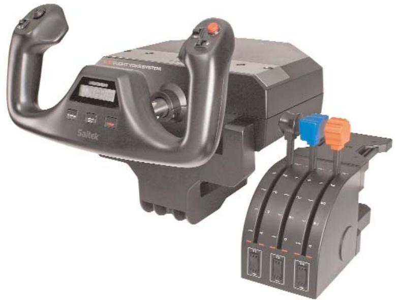
Congratulations on buying the Saitek Pro Flight Yoke System. The Pro Flight Yoke features realistic controls configurable for all the major flight simulation software to make your flying experiences more realistic.
8-way point of view hat switch
2-way rocker switch
Single function button (back of left handle)
2-way rocker switch
(point to both switches)
Single function button
3 position Mode switch (back of right handle)
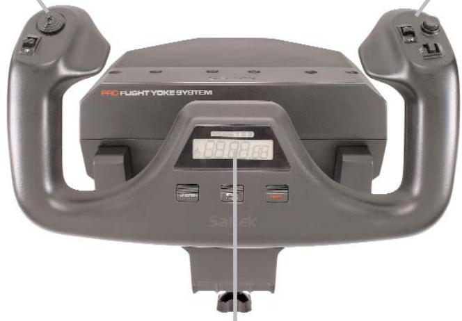
Chronograph: Accurate time and stopwatch function to time each leg of your flight. Display also indicates which programming mode is selected.
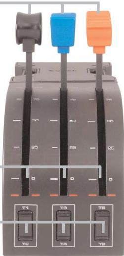
Detachable lever knobs to configure any
combination of throttle, flaps, mixture or prop pitch.
Smooth travel levers with 0 button detent
Three 2-way rocker switches
Installing the flight yoke and throttle quadrant
First, fix the Flight Yoke to your table or desk by inserting the prongs of the mounting clamp into the holes on the Yoke base and then tightening the screw
mechanism until the yoke is firmly attached (be careful not to overtighten the screw as you may
damage the clamp). Next, screw the mounting plate to the Throttle Quadrant using the four screws provided. You can
screw the plate to one of two sides of the quadrant depending on how you want to mount the Quadrant - either in front and
below your table or on top of it. Please note that whichever way you choose to mount
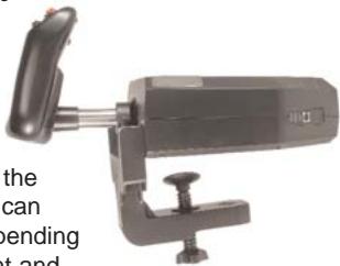
the quadrant, ensure that as you look at the unit the rocker switches are at the bottom.
Now tighten the throttle unit clamp's screw mechanism until it is firmly attached to your table. You can also position the throttle quadrant on the left or right side of the flight yoke.
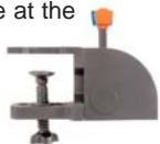
Now, connect the Throttle Quadrant to back of the flight yoke with the PS/2-style connector provided.
Use the integrated USB Hub on the side of the Pro Flight Yoke to easily connect other parts of the Saitek Pro Flight range of products, such as additional Pro Flight Throttle Quadrants, Pro Flight Rudder Pedals or other peripherals.
Software installation for users of Windows® XP, XP64 and Vista
A) Drivers Only For Typical Users
1. With your computer switched on, close down any programs that are currently running and insert the Installation CD into your CD-ROM drive.
2. When the Introduction Screen appears, click Install Software to continue. If the CD does not run automatically, select Start from the Windows® Taskbar, then Run and type D:\Setup.exe and click OK - where D:\ is letter of your CD-ROM drive.
3. When the Welcome screen appears, click Next to continue.
4. After reading the Disclaimer, select the I accept the terms of the Disclaimer option and click Next to continue.
5. At the Driver Setup screen, if you haven't already done so, plug the USB cable into one of your computer's USB ports and click on Next.
6. At the Driver Setup screen, click Next to test your controller.
7. When the Saitek Controller screen appears, try out all your controller's buttons and controls to show that it is working properly. When you have finished, click OK.
8. At the Software Setup screen, select Do not install the SST Programming Software and click Next. The Programming Software can be installed at a later date by following instruction (B). below
-
At the Registration screen, select Check this box to register now and follow the on-screen instructions, or you can choose to select this option later.
-
Click on Finish to complete the installation.
B) Drivers and Programming Software For Advanced Users
Follow points 1 - 7 of the install procedure in A), then at the Software Setup screen, select Install the SST Programming Software and click Next.
In the following Software Setup screen, click Next and follow the on-screen instructions. At this point you will be asked to install such features as the Saitek Magic Mouse, HID-compliant mouse, Saitek Magic Keyboard and HID Keyboard Device (these are what XP calls the Programming elements of your Saitek controller).
Continue to click on Next and Finish to accept the installation until the Registration screen appears.
At the Registration screen, select Check this box to register now and follow the on-screen instructions, or do not select this option and register later.
Upon completion of the installation, you have the option to Run Profile Editor, which will give you a view of the programming environment. If you do not wish to see the Profile Editor at this point, just uncheck the box and click on Finish to complete the installation.
IMPORTANT INFORMATION
Driver updates
From time to time there may be updates to the driver and programming software for this product. You can check for the latest software updates by visiting the Saitek website (www.saitek.com) and clicking on Downloads. A drop down menu will appear. Select Drivers and Software.
Configuring your Saitek Pro Flight Yoke and Throttle Quadrant for Microsoft Flight Simulator 9 and FS X
The Saitek Pro Flight Yoke System's buttons, controls and axes correspond to commonly used functions in Microsoft FS 9 and FS X according to the tables below. As with any software, if you wish to change the function of a button or control, you will need to change the settings of the game software.
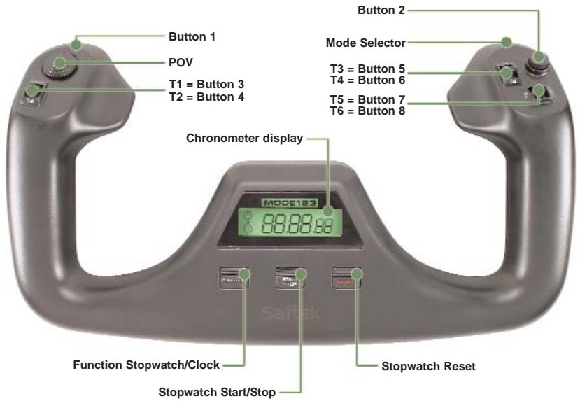
Function Overview
Flight Yoke controls and corresponding functions in Microsoft Flight Simulator
| Function | Default function in FS 9 and FS X | |
| Yoke axis | X axis | Ailerons |
| Y axis | Elevator | |
| Main Buttons | Button 1 | Brakes (apply/release) |
| T1 (button 3) | Elevator trim down | |
| T2 (button 4) | Elevator trim up | |
| T3 (button 5) | Flaps retract incrementally | |
| T4 (button 6) | Flaps extend incrementally | |
| T5 (button 7) | Knee board display/hide | |
| T6 (button 8) | Landing gear up/down | |
| Button 2 | Views (cycle) | |
| POV | Panoramic viewing | |
| Other Controls | Mode switch | Switches Mode when using Saitek Smart Technology (SST) programming software |
| Clock Buttons | Function | Clock / stopwatch swap |
| Start/Stop | Start/stop stopwatch | |
| Reset | Reset stopwatch | |
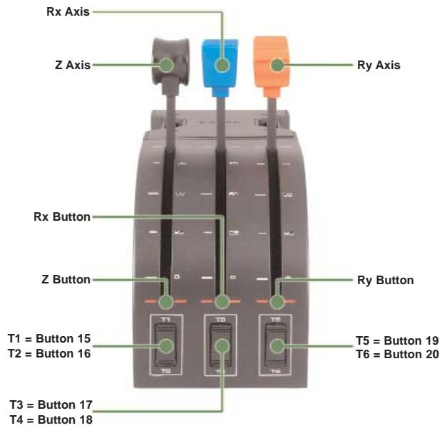
Function Overview
Quadrant controls and corresponding functions in Microsoft Flight Simulator
| Function | Default function in FS 9 and FS X | |
| Quadrant Axis | Z axis | Throttle |
| Rx axis | Flaps | |
| Ry axis | Spoiler | |
| Axis buttons | Z button | Assignable in game |
| Rx button | Assignable in game | |
| Ry button | Assignable in game |
| Toggle switches | T1 (button 15) | Assignable in game |
| T2 (button 16) | Assignable in game | |
| T3 (button 17) | Assignable in game | |
| T4 (button 18) | Assignable in game | |
| T5 (button 19) | Assignable in game | |
| T6 (button 20) | Assignable in game |
How to assign Pro Flight Yoke controls to Flight Simulator functions
If you wish to change the controls or set up the additional buttons that have not been assigned by Flight Simulator automatically, then you must use the Assignments (Flight Simulator 2004) or Controls (Flight Simulator X) screen within the game. This is accessed from the Settings menu within the game.
When you access the Assignments/Controls screen in Flight Simulator, ensure that the Saitek Pro Flight Yoke is selected in the option labelled Joystick Type.
If you wish to reassign any of the buttons on your controller, you must first select the Buttons/Keys tab at the top of the window.
If you wish to reassign any of the axes on your controller, (the yoke itself or the levers on the throttle quadrant) you must select Joystick Axes (Flight Simulator 2004) or Control Axes (Flight Simulator X) at the top of the window.
Once you have done this, simply find the command that you want to assign to your controller from the list of commands, click it and then click the Change Assignment
button. A window will appear asking you to move the part of your controller that you want to assign to that command - press/move the button/axis that you want to assign to that command and then click OK.
Tip: You may find that when you assign the levers on the quadrant to a command, that they don't appear to work when you test them in the game. If this happens then you must look in the Sensitivities screen (Flight Simulator 2004) or the Calibration tab of the Controls screen (Flight Simulator X) of the game, select the axis command in the list there and ensure that the Sensitivity isn't set too low (set the horizontal sensitivity slider control to around 70% ).
Programming your Saitek Pro Flight Yoke and Throttle Quadrant with Saitek Smart Technology software
Introducing Saitek Smart Technology programming software
Saitek Smart Technology Programming Software (SST) is the software Saitek supplies to configure your Saitek controller for enhanced functionality. SST delivers a powerful set of features, allowing you to program your device with the ultimate configuration for total interaction. Despite a level of sophistication previously unseen in the market, and because of the Saitek Smart Technology inside, the software remains simple and intuitive to use.
For a complete guide on how to program your Saitek controller, visit the Saitek website at www.saitek.com or look at the help tab on your programming software menu.
Features of Smart Technology programming software:
- Quick and easy setup in any game
- Personalize the controller settings for your favorite games
- Configure your controller with an on-screen 3D model and interface
- Multiple setup option for each controller - ideal if a controller is used by several people and you need more than one profile per device
- Program special moves with sophisticated timing features
- Special game setups available as 'Profiles' from the Saitek website and on the Smart Technology CD
- Download the latest version of Saitek Smart Technology software from the Saitek website
What is a Profile?
A Profile is a custom setup for improved gameplay - consisting of a set of commands that are pre-assigned to the buttons or axes of your controller. Pre-written Profiles are available on the Product Companion Disk that accompanies this device or on the Saitek Website - www.saitek.com. (Please check the website for new or improved Profiles, which are added regularly).
How do I program my controller?
After getting to know your controller, you can start creating your own personal Profiles with the Saitek Smart Technology programming software (SST). This software has virtually unlimited programming capabilities and allows you to customize the controller to your exact gaming needs.
The Profile Editor allows you to program the buttons on your controller to perform different actions within your games - this is especially useful if the game you are using does not have its own screen that allows reconfiguring of your buttons.
Getting Started
- Double-click on the Saitek Smart Technology icon the install left on your desktop.
- In the Profile Editor, choose the control to which you wish to assign a keyboard command. You do this by left-clicking on the control's cell in the control list on the right of the screen.
- With the cursor flashing, type in the key commands and then click on the green tick mark when complete.
- Repeat this procedure for all the buttons you would like to program and then click File, Save at the top of the Profile Editor window.
- Give the profile a name (it is recommended you name it after the game for which the profile is intended) and then click Save.
-
To enable the profile either click the blue Profile Now icon at the top of the Profile Editor or right-click on the controller icon in your taskbar and select the name of the profile from the pop-up list of options.
-
You will notice that when a profile is loaded that the controller icon in your taskbar has a green square behind it, indicating that a profile is currently loaded. If you wish to unload a profile simply right-click on the controller icon and click Clear Profile from the pop-up list of options.
If you require more detailed assistance with using the SST Programming Software, click on Help at the top of the Profile Editor and then Manual.
Technical Support
Nearly all the products that are returned to us as faulty are not faulty at all - they have just not been installed properly.
If you experience any difficulty with this product, please first visit our website www.saitek.com. The technical support area will provide you with all the information you need to get the most out of your product and should solve any problems you might have.
If you do not have access to the internet, or if the website cannot answer your question, please contact your local Saitek Technical Support Team. We aim to offer quick, comprehensive and thorough technical support to all our users so, before you call, please make sure you have all the relevant information at hand.
To find your local Saitek Technical Support Center, please see the separate Technical Support Center sheet that came packaged with this product.
Conditions of Warranty
- Warranty period is 2 years from date of purchase with proof of purchase submitted.
- Operating instructions must be followed.
- Specifically excludes any damages associated with leakage of batteries. Note: Batteries can leak when left unused in a product for a period of time, so it is advisable to inspect batteries regularly.
- Product must not have been damaged as a result of defacement, misuse, abuse, neglect, accident, destruction or alteration of the serial number, improper electrical voltages or currents, repair, alteration or maintenance by any person or party other than our own service facility or an authorized service center, use or installation of non-Saitek replacement parts in the product or the modification of this product in
any way, or the incorporation of this product into any other products, or damage to the product caused by accident, fire, floods, lightning, or acts of God, or any use violative of instructions furnished by Saitek plc.
- Obligations of Saitek shall be limited to repair or replacement with the same or similar unit, at our option. To obtain repairs under this warranty, present the product and proof of purchase (eg, bill or invoice) to the authorized Saitek Technical Support Center (listed on the separate sheet packaged with this product) transportation charges prepaid. Any requirements that conflict with any state or Federal laws, rules and/or obligations shall not be enforceable in that particular territory and Saitek will adhere to those laws, rules, and/or obligations.
- When returning the product for repair, please pack it very carefully, preferably using the original packaging materials. Please also include an explanatory note.
IMPORTANT: To save yourself unnecessary cost and inconvenience, please check carefully that you have read and followed the instructions in this manual.
This warranty is in Lieu of all other expressed warranties, obligations or liabilities. ANY IMPLIED WARRANTYES, OBLIGATIONS, OR LIABILITIES, INCLUDING BUT NOT LIMITED TO THE IMPLIED WARRANTYES OF MERCHANTABILITY AND FITNESS FOR A PARTICULAR PURPOSE, SHALL BE LIMITED IN DURATION TO THE DURATION OF THIS WRITTEN LIMITED WARRANTY. Some states do not allow limitations on how long an implied warranty lasts, so the above limitations may not apply to you. IN NO EVENT SHALL WE BE LIABLE FOR ANY SPECIAL OR CONSEQUENTIAL DAMAGES FOR BREACH OF THIS OR ANY OTHER WARRANTY, EXPRESS OR IMPLIED, WHATSOEVER Some states do not allow the exclusion or limitation of special, incidental or consequential damages, so the above limitation may not apply to you. This warranty gives you specific legal rights, and you may also have other rights which vary from state to state.

This symbol on the product or in the instructions means that your electrical and electronic equipment should be disposed at the end of its life separately from your household waste. There are separate collection systems for recycling in the EU.
For more information, please contact the local authority or your retailer where you purchased the product.
FCC Compliance and Advisory Statement
Warning: Changes or modifications to this unit not expressly approved by the party responsible for compliance could void the user's authority to operate the equipment. This device complies with Part 15 of the FCC Rules. Operation is subject to the following two conditions:
1 This device may not cause harmful interference, and;
2 This device must accept any interference received, including interference that may cause undesired operation.
NOTE: This equipment has been tested and found to comply with the limits for a Class B digital device, pursuant to Part 15 of the FCC Rules. These limits are designed to provide reasonable protection against harmful interference in a residential installation. This equipment generates, uses and can radiate radio frequency energy and, if not installed and used in accordance with the instructions, may cause harmful interference to radio communications. However, there is no guarantee that interference will not occur in a particular installation. If this equipment does cause harmful interference to radio or television reception, which can be determined by turning the equipment off and on, the user is encouraged to try to correct the interference by one or more of the following measures:
Reorient or relocate the receiving antenna;
- Increase the separation between the equipment and receiver;
- Connect the equipment into an outlet on a circuit different from that to which the receiver is connected;
- Consult the dealer or an experienced radio/TV technician for help.
Saitek Industries, 2295 Jefferson Street, Torrance, CA 90501, USA
Canada ICES-003
Operation is subject to the following two conditions:
1 This device may not cause interference, and;
2 This device must accept any interference, including interference that may cause undesired operation of the device.
This Class B digital apparatus complies with Canadian ICES-003.
Hat switch a 8 vie "point of view"
PZ45_Pro Flight yoke_QSG2.qxd 05/09/2007 09:57 Page 70
70
71
Saitek
Pro Flight Yoke System User Guide
www.saitek.com
Version 1.2 - 05/09/07
© 2007 Saitek Ltd
Made and printed in China
All trademarks are the property of their respective owners. PZ45


- Pro Flight Yoke System
- Installing the flight yoke and throttle quadrant
- Software installation for users of Windows® XP, XP64 and Vista
- IMPORTANT INFORMATION
- Driver updates
- Configuring your Saitek Pro Flight Yoke and Throttle Quadrant for Microsoft Flight Simulator 9 and FS X
- Flight Yoke controls and corresponding functions in Microsoft Flight Simulator
- Quadrant controls and corresponding functions in Microsoft Flight Simulator
- How to assign Pro Flight Yoke controls to Flight Simulator functions
- Programming your Saitek Pro Flight Yoke and Throttle Quadrant with Saitek Smart Technology software
- Introducing Saitek Smart Technology programming software
- Features of Smart Technology programming software:
- What is a Profile?
- How do I program my controller?
- Getting Started
- Technical Support
- Conditions of Warranty
- FCC Compliance and Advisory Statement
- Canada ICES-003
- Saitek
- Pro Flight Yoke System User Guide
Brand : SAITEK
Model : PRO FLIGHT YOKE SYSTEM
Category : Flight controllers