
FU8350 - Security System ABUS - Free user manual and instructions
Find the device manual for free FU8350 ABUS in PDF.


| Product Type | Security System |
| Brand | ABUS |
| Model | FU8350 |
| Dimensions (L x W x H) | 120 x 80 x 30 mm |
| Weight | 200 g |
| Power Supply | 2 AA batteries (not included) |
| Battery Life | Approximately 1 year under normal use |
| Main Functions | Motion detection, audible alarm, door/window opening sensor |
| Alarm Volume | 100 dB |
| Detection Range | Up to 10 meters (90° angle) |
| Operating Temperature | 0 °C to 40 °C |
| Care and Cleaning | Clean with a soft, dry cloth; avoid chemical products |
| Security | Tamper protection (anti-theft) |
| Spare Parts | Replacement batteries available; ABUS after-sales service |
| Repairability | Repairability index: 7.5/10 (according to French standard) |
| Certifications | VdS, CE |
| Use | Indoor only |
| Warranty | 2 years |
Frequently Asked Questions - FU8350 ABUS
User questions about FU8350 ABUS
0 question about this device. Answer the ones you know or ask your own.
Ask a new question about this device
Download the instructions for your Security System in PDF format for free! Find your manual FU8350 - ABUS and take your electronic device back in hand. On this page are published all the documents necessary for the use of your device. FU8350 by ABUS.
USER MANUAL FU8350 ABUS
natural_image
White square electrical outlet switch with a red indicator light (no text or symbols visible)Wireless motion sensor Détecteur de mouvement radio Draadloze bewegingsmelder Trådløs bevægelsesmelder Rilevatore di movimento via radio
Vorwort
natural_image
Architectural floor plan showing a rectangular room with a central square and decorative elements (no text or labels)natural_image
Architectural floor plan showing a central circular component with surrounding walls and structural brackets (no text or labels)natural_image
Technical line drawing of a mechanical assembly with no visible text or symbolsnatural_image
Technical line drawing of a mechanical component with no visible text or symbols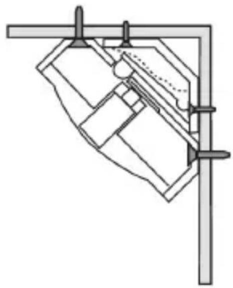
natural_image
Pure mechanical assembly diagram without any text, numbers, or symbolsEinlernen
Many thanks for your purchase of this wireless motion sensor. In choosing our product, you now have a piece of equipment that is built according to state-of-the-art technology.
This product complies with current domestic and European regulations. Conformity has been proven, and all related certifications are available from the manufacturer on request.
To maintain this status and to guarantee safe operation, it is your obligation to observe these operating instructions! In the event of questions, please contact your local specialist dealer.

Pay attention to the notes and instructions in these operating instructions! If you do not follow these instructions, your guarantee claim becomes invalid! No liability can be accepted for resulting damages!
No part of the product may be changed or modified in any way.
Introduction
The FU8350 passive infrared motion sensor (PIR) is an internal sensor for use in combination with the Secvest
wireless alarm centre or Terxon alarm centre with wireless extension. The PIR sensor is used to detect the movement of body heat. It has a fan-shaped detection area with a radius of approximately 15 metres at an aperture angle of 90°. The housing is protected by an internal tamper contact. A stamping on the rear side of the housing can be removed, which is used as a tamper contact against unauthorised removal from the wall.
Safety information

Battery warning!
The device is supplied with direct current from a 3.6 V lithium battery. To guarantee a long working life and avoid fire and injury, please note the following:
- Do not dispose of the battery in domestic waste.
- The battery must not be directly exposed to heat or sunlight, and must not be stored in a place with a very high temperature.
- The battery must not be burned.
-
The battery must not come into contact with water.
-
The battery must not be dismantled, pierced or otherwise damaged.
- The battery contacts must not be short-circuited.
- The battery must be kept away from small children.
- The battery cannot be recharged.

Caution!
Improper or careless installation work may lead to misinterpretation of signals. This could result in false alarms. The costs resulting from the deployment of emergency services (e.g. fire or police) are borne by the operator of the equipment.
Scope of delivery
Wireless motion sensor
1 x screw (3x10 mm)
2 x wall plugs (6x25 mm)
2 x screws (3x22 mm)
1 x 3.6 V battery
Corner adapter
Multilingual instructions
Technical data
| Environment class I | |
| Security level 2 (EN5013) | 1-3) |
| White-light filter > 2000 lux | |
| Detection area 15 m x 90° | |
| Operating temperature -10 °C to +55 °C | |
| Humidity < 85% relative humidity | |
| Dimensions 81 x 73 x 47 mm (HxWxD) | |
| Weight | 140 g |
| HF immunity 10 V/m | |
| Power supply 3.6 V DC (lithium AA battery) | |
| “Low battery” error message | < 2.4 V |
| Frequency | 868.6625 MHz |
| HF transmission power | 10 mW (antenna input) |
| Tamper monitoring Yes | |
| Supervision monitoring Every 4 minutes | |
| Housing material ABS |
Subject to alterations and errors.
Position
The sensor can either be mounted flat on a wall or in a corner. The following illustrations show the range of the sensor.
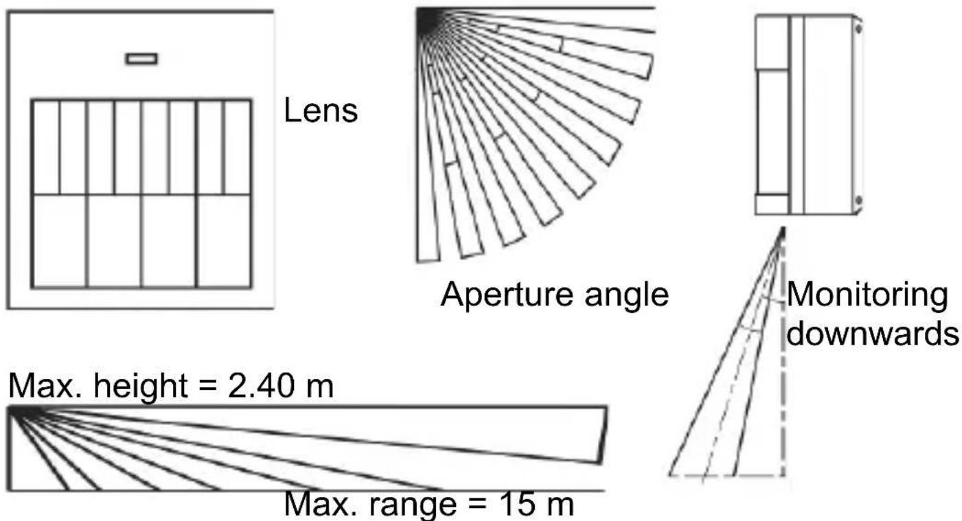
For optimal detection, the sensor should be attached at a height between 180 cm and 240 cm.
The sensor must NOT be attached in the following locations:
- Opposite heat sources or windows
- Above heaters
-
Next to the floor
-
Near large metal structures
- Less than 1 metre away from power or gas lines
- Near electronic or wireless devices
- Less than 30 mm away from the ceiling
Installation
Open the housing by loosening the screw on the bottom of the sensor and removing the rear part of the housing.
Insert the enclosed 3.6 V AA lithium battery correctly.
Note:
If the activity LED on the sensor flashes continuously, then an error has occurred or the battery is empty. Replace the battery, then check whether the LED functions normally.
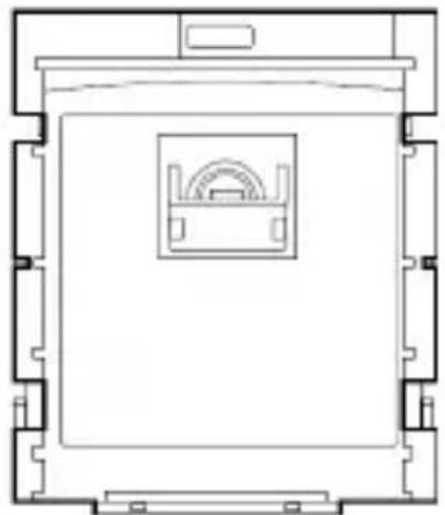
Pet immunity
- Remove the PCB.
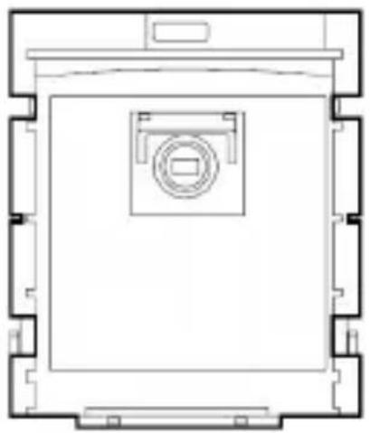
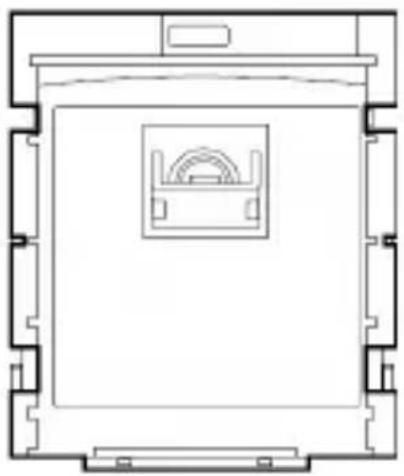
- Fold the sensor cover downwards. This hides all lines apart from the upper one.
- Replace the PCB.
natural_image
Architectural floor plan showing room layout with central circular vent (no text or labels)Raised sensor cover
Lowered sensor cover
natural_image
Architectural floor plan showing room layout with central framed space and decorative elements (no text or labels)Note: When delivered, the sensor cover may be set in the lowered position. Check this as a possible cause if the sensor does not detect any movement.
Attaching the rear housing side
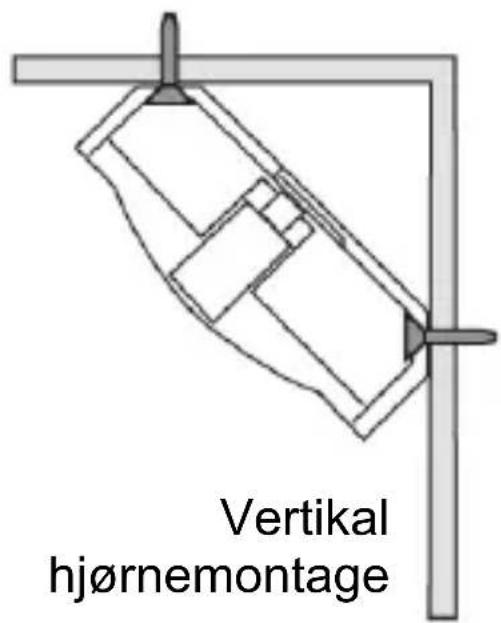
The sensor is designed for mounting on a wall or in a corner. Holes have already been cut out of the rear for this purpose. Only use suitable wall plugs and screws for installation. When choosing the installation location, check the range of view and communication with the alarm centre (see “PIR test”).

natural_image
Pure architectural line drawing of a vertical support structure without any text, numbers, or symbolsFlat wall installation

Wall tamper contact
To use the wall tamper contact, proceed as follows:
- Open the hole on the rear of the sensor. Make sure that the opening is large enough for the head of the tamper switch.
- Mark the position of the hole on the wall where the sensor is to be fitted. Drill a hole on the mark, then insert a suitable wall plug and insert a screw (M3). The screw head must not be more than 2.5 ~mm from the wall surface.
- Fasten the rear housing cover to the wall, making sure the head of the screw protrudes through the opening and presses against the tamper switch after the sensor housing is attached (see illustration). If this is not the case, then the screw must be unscrewed further as necessary.

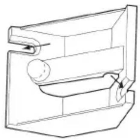
Corner tamper contact
To use the corner tamper contact, proceed as follows:
- Open the hole on the rear of the sensor. Make sure that the opening is large enough for the head of the tamper switch.
- Attach the enclosed corner tamper bar to the desired position. Ensure that the pin on the end of the arm is on the left-hand side.
- Attach the rear side of the sensor onto the bar and fasten it to the wall. Ensure that the pin on the bar passes through the hole on the rear housing side without any obstructions.
natural_image
Technical line drawing of a mechanical component with no visible text or symbols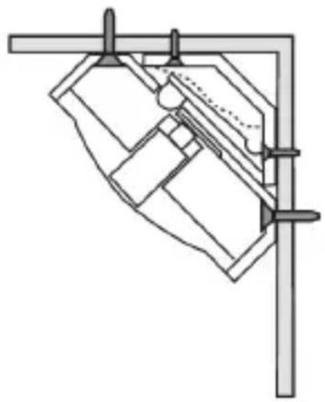
natural_image
Pure mechanical assembly diagram without any text, numbers, or symbolsTraining
- Set the Secvest alarm system or the wireless extension to learning mode. See the receiver instructions for more details.
- Wireless variations:
Activate the tamper contact of the motion sensor to send a tamper message to the wireless alarm system.
IR variation:
Point the LED of the motion sensor at the IR receiver of the wireless extension (RFX). Trigger the tamper contact on the motion sensor.
- Make sure that the motion sensor is recognised by your wireless alarm system / extension, then close the housing.
PIR test
- Switch the alarm system to walk test mode (see the relevant installation instructions).
- Leave the zone monitored by the sensor and wait until the idle time expires after each test (see "Idle time").
- Conduct different walk tests to test the monitored zone.
- If the sensor is unintentionally triggered, check the installation location again (see "Position").
Idle time
To increase the battery life, the sensor has an idle time function. You can reduce the idle time from 3 minutes (default setting) to 1 minute by removing the jumper from the PCB. However, this setting also shortens the battery life.
To simplify the sensor test, the idle time in the first 30 minutes after battery insertion or after the tamper switch is pressed is only 10 seconds.
This product complies with the requirements of the EU directive: 1995/5/EC “Directive on radio and telecommunications terminal equipment and the mutual recognition of their conformity”.
The declaration of conformity can be ordered from:
natural_image
Simple line drawing of a cabinet or rack with vertical panes and a top fixture (no text or symbols)Objectif

natural_image
Radial arrangement of rectangular blocks resembling a fan or fan blade, with no text or symbols present.Angle d'ouverture

natural_image
Pure geometric diagram of a rectangular frame with internal vertical divisions and corner holes (no text or symbols)Hauteur max. 2,40m

natural_image
Pure geometric lines radiating from a corner point (no text or symbols)Portée max. 15m

natural_image
Architectural floor plan of a room with a central circular vent (no text or labels)natural_image
Architectural floor plan showing a central room with arched windows and a central staircase (no text or labels)natural_image
Pure technical line drawing of a vertical structural component without any text, numbers, or symbolsMontage mural plat

Contact de sabotage mural
natural_image
Technical line drawing of a mechanical or electrical enclosure with no visible text, numbers, or symbols.natural_image
Technical diagram showing a door mechanism with a diagonal line indicating direction, next to a brick wall (no text or symbols)natural_image
Technical line drawing of a mechanical component with no visible text or symbols
natural_image
Technical line drawing of a mechanical assembly with no visible text or symbolsApprentissage
natural_image
Architectural floor plan showing room layout with central circular component (no text or labels)Opgetilde sensorafdekking
Neergelaten
sensorafdekking
natural_image
Architectural floor plan showing a central room with a circular vent and wall-mounted fixture (no text or labels)natural_image
Pure architectural line drawing of a vertical structure with horizontal supports and a right-angle detail (no text or symbols)Platte wandmontage

Wand-sabotagecontact
natural_image
Technical line drawing of a mechanical assembly with no visible text or symbolsnatural_image
Technical line drawing of a mechanical component with no visible text or symbols
natural_image
Pure mechanical assembly diagram without any text, numbers, or symbolsInlezen
natural_image
Architectural floor plan showing room layout with central circular vent (no text or labels)natural_image
Architectural floor plan showing room layout with central framed space and decorative elements (no text or labels)natural_image
Pure architectural line drawing of a vertical structure with horizontal supports and a right-angle bracket (no text or symbols)Flad vægmontage
Væg-sabotagekontakt
natural_image
Technical line drawing of a mechanical component with no visible text or symbols
natural_image
Pure mechanical assembly diagram without any text, numbers, or symbolsIndlæring
natural_image
Architectural floor plan showing a room with a central circular vent and surrounding structural elements (no text or labels)natural_image
Architectural floor plan showing room layout with central opening and side walls (no text or labels)natural_image
Pure architectural line drawing of a vertical support structure without any text, numbers, or symbolsnatural_image
Technical line drawing of a mechanical assembly with no visible text or symbolsnatural_image
Diagram showing a door mechanism with a diagonal line indicating direction, next to a brick wall (no text or symbols)natural_image
Technical line drawing of a mechanical component with no visible text or symbols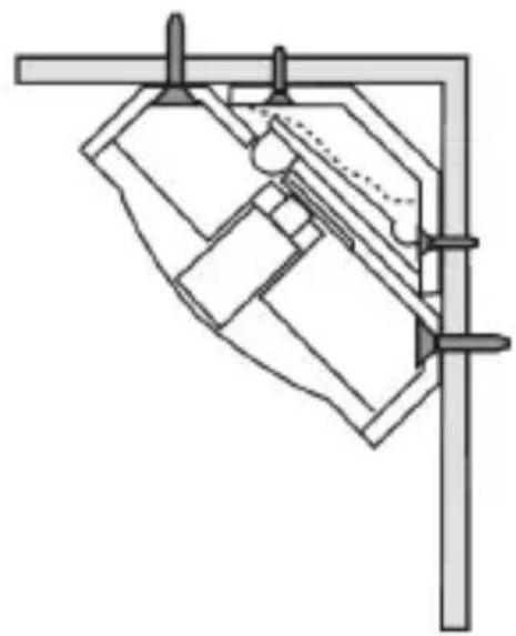
natural_image
Technical line drawing of a mechanical assembly with no visible text or symbolsApprendimento



- Vorwort
- Einlernen
- Introduction
- Safety information
- Battery warning!
- Caution!
- Scope of delivery
- Corner adapter
- Multilingual instructions
- Position
- Installation
- Pet immunity
- Attaching the rear housing side
- Wall tamper contact
- Corner tamper contact
- Training
- PIR test
- Idle time
- Contact de sabotage mural
- Apprentissage
- Wand-sabotagecontact
- Inlezen
- Væg-sabotagekontakt
- Indlæring
- Apprendimento
Brand : ABUS
Model : FU8350
Category : Security System