
GEX-P5700TVP - Digital decoder PIONEER - Free user manual and instructions
Find the device manual for free GEX-P5700TVP PIONEER in PDF.


| Product type | Digital decoder |
| Brand | Pioneer |
| Model | GEX-P5700TVP |
| Dimensions (W × H × D) | 180 × 40 × 130 mm |
| Weight | 0.5 kg |
| Power supply | 12 V DC (AC adapter included) |
| Power consumption | 8 W |
| Broadcast standards | DVB-T, DVB-T2 |
| Maximum resolution | 1080p |
| Input connectors | RF antenna, AV input (RCA) |
| Output connectors | HDMI, AV (RCA), digital optical audio |
| Main features | Digital terrestrial TV reception, teletext, channel list, auto scan |
| Maintenance and cleaning | Clean with a soft dry cloth. Do not use abrasive products. |
| Safety | Disconnect power before cleaning. Do not expose to moisture. |
| Spare parts and repairability | Parts available via Pioneer after-sales service. Repair possible by a professional. |
| General information | Designed for automotive or home use. Compatible with Pioneer audio systems. |
Frequently Asked Questions - GEX-P5700TVP PIONEER
User questions about GEX-P5700TVP PIONEER
0 question about this device. Answer the ones you know or ask your own.
Ask a new question about this device
Download the instructions for your Digital decoder in PDF format for free! Find your manual GEX-P5700TVP - PIONEER and take your electronic device back in hand. On this page are published all the documents necessary for the use of your device. GEX-P5700TVP by PIONEER.
USER MANUAL GEX-P5700TVP PIONEER
This product conforms to new cord colors.
Connecting the Units 1
Power cable connection 2
When using this unit as "SRC : OSD OFF" mode .... 3
AV-BUS cable 4
When using this unit as “SRC : OSD ON” mode .... 4
When using this unit as "STAND ALONE" mode .... 5
TV antenna connection 6
Rear display connection 7
Installation 8
Switching the operation mode.... 8
Installing the unit 8
Note:
- This unit is for vehicles with a 12-volt battery and negative grounding. Before installing it in a recreational vehicle, truck, or bus, check the battery voltage.
- To avoid shorts in the electrical system, be sure to disconnect the (-) battery cable before beginning installation.
- Refer to the owner's manual for details on connecting the other units, then make connections correctly.
- Secure the wiring with cable clamps or adhesive tape. To protect the wiring, wrap adhesive tape around them where they lie against metal parts.
- Route and secure all wiring so it cannot touch any moving parts, such as the gear shift, handbrake and seat rails. Do not route wiring in places that get hot, such as near the heater outlet. If the insulation of the wiring melts or gets torn, there is a danger of the wiring short-circuiting to the vehicle body.
- Don't pass the yellow lead through a hole into the engine compartment to connect to the battery. This will damage the lead insulation and cause a very dangerous short.
- Do not shorten any leads. If you do, the protection circuit may fail to work when it should.
- Never feed power to other equipment by cutting the insulation of the power supply lead of the unit and tapping into the lead. The current capacity of the lead will be exceeded, causing over heating.
- When replacing fuse, be sure to only use fuse of the rating prescribed on the fuse holder.
- To prevent incorrect connection, the input side of the IP-BUS connector is blue, and the output side is black. Connect the connectors of the same colors correctly.
- To minimize noise locate the TV antenna cable, radio antenna cable and RCA cable as far away from each other as possible.
- Cords for this product and those for other products may be different colors even if they have the same function. When connecting this product to another product, refer to the supplied manuals of both products and connect cords that have the same function.
Power cable connection

Yellow
To terminal always supplied with power regardless of ignition switch position.
Red
(Connect this lead only when this unit is used as STAND ALONE mode.)
To electric terminal controlled by ignition switch (12 V DC) ON/OFF.
Black (ground)
To vehicle (metal) body
Connection method

- Clamp the lead.


- Clamp firmly with needle-nosed pliers.
Note:
- The position of the parking brake switch depends on the vehicle model. For details, consult the vehicle Owner's Manual or dealer.
Light green
Used to detect the ON/OFF status of the parking brake. This lead must be connected to the power supply side of the parking brake switch.

When using this unit as "SRC : OSD OFF" mode

flowchart
graph TD
    A["AV-BUS cable (supplied)"] --> B["Blue"]
    B --> C["3 m"]
    C --> D["IP-BUS cable (supplied)"]
    D --> E["3 m"]
    E --> F["Black"]
    F --> G["This unit"]
    G --> H["Blue"]
    G --> I["Black"]
    H --> J["IP-BUS cable (sold separately)"]
    I --> K["IP-BUS STAND ALONE"]
    K --> L["DVD Player (e.g. XDV-P9II) (sold separately)"]
    L --> M["Blue"]
    L --> N["Black"]
    N --> O["Multi-CD Player (sold separately)"]
    P["AV receiver (e.g. AVH-P5700DVD) (sold separately)"] --> Q["Yellow"]
    R["Pioneer navigation unit (e.g. AVIC-800DVD) (sold separately)"] --> S["Black"]
    T["Rear display (e.g. AVD-W6200) (sold separately)"] --> U["To video 1 input"]
    V["RCA cable (sold separately)"] --> W["To video 2 input"]
    X["White/Red"] --> Y["White/Red"]
    Z["Blue"] --> AA["Black"]
    AB["White/Red"] --> AC["White/Red"]
    AD["Yellow"] --> AE["To video output"]
    AF["Blue"] --> AG["Yellow"]
    AH["Black"] --> AI["To video output"]
AV-BUS cable

When using this unit as "SRC : OSD ON" mode
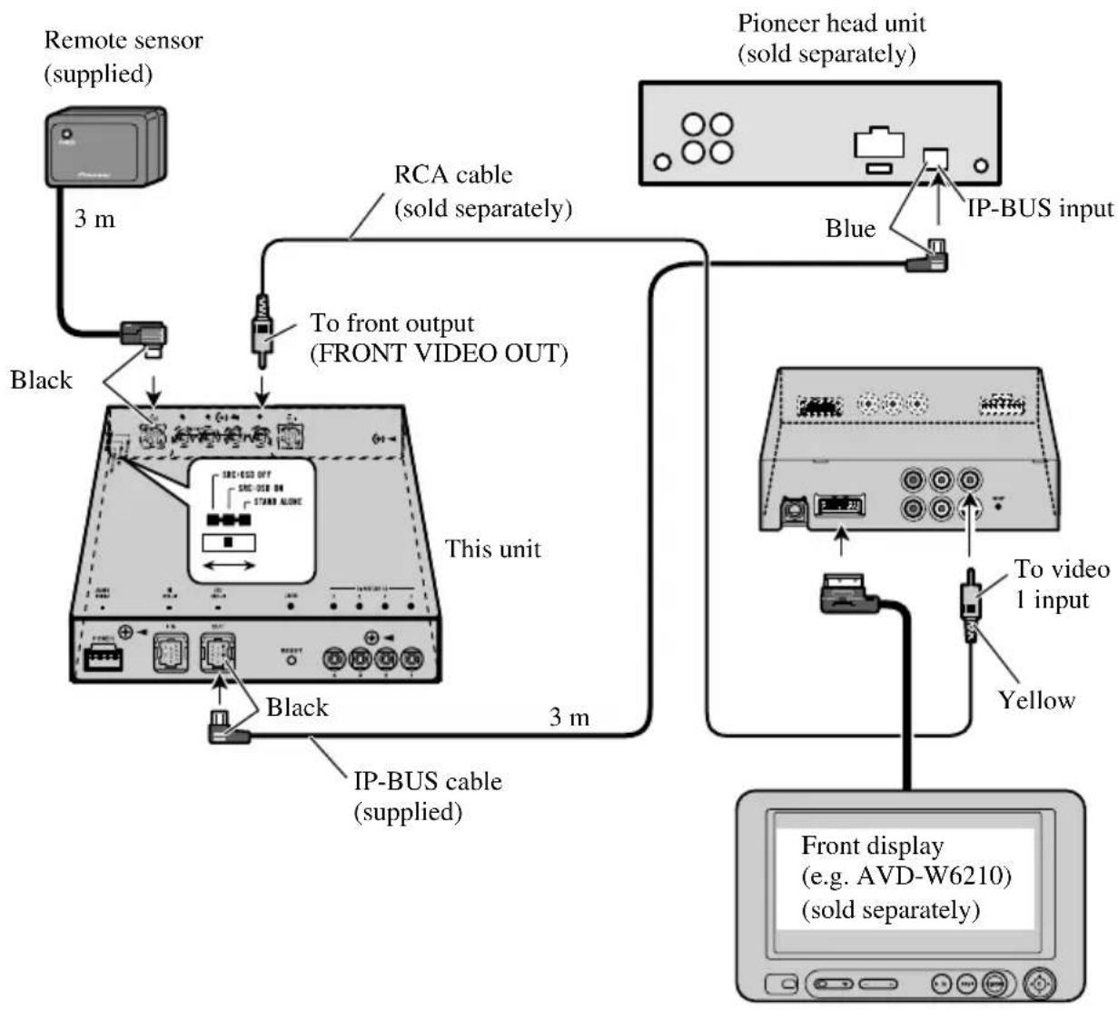
flowchart
graph TD
    A["Remote sensor (supplied)"] -->|3 m| B["Black"]
    B --> C["This unit"]
    C --> D["IP-BUS cable (supplied)"]
    D --> E["Pioneer head unit (sold separately)"]
    E --> F["Blue"]
    F --> G["IP-BUS input"]
    G --> H["Yellow"]
    H --> I["To video 1 input"]
    I --> J["Front display (e.g. AVD-W6210) (sold separately)"]
When using this unit as "STAND ALONE" mode

flowchart
graph TD
    A["Rear display (e.g. AVD-W6200) (sold separately)"] --> B["To video 1 input"]
    B --> C["Remote sensor (supplied)"]
    C --> D["3 m"]
    D --> E["To rear out (REAR OUT)"]
    E --> F["Black"]
    F --> G["To front out (FRONT VIDEO OUT)"]
    G --> H["Front display (e.g. AVD-W6210) (sold separately)"]
    H --> I["Yellow"]
    I --> J["To video 1 input"]
    J --> K["26-pin cable (supplied with Pioneer navigation unit)"]
    K --> L["Pioneer navigation unit (e.g. AVIC-800DVD) (sold separately)"]
    L --> M["Black"]
This unit
TV antenna connection

Fig. 3
Connecting the Units
Rear display connection
Note:
- Output to this product's Rear Display is ON when the Head Unit's source is TV.
If the Head Unit's source is anything other than TV or Head Unit is OFF, pressing POWER button on the supplied remote control enables you to operate TV independently for the Rear Display. - Output from this product's rear audio output is monaural.
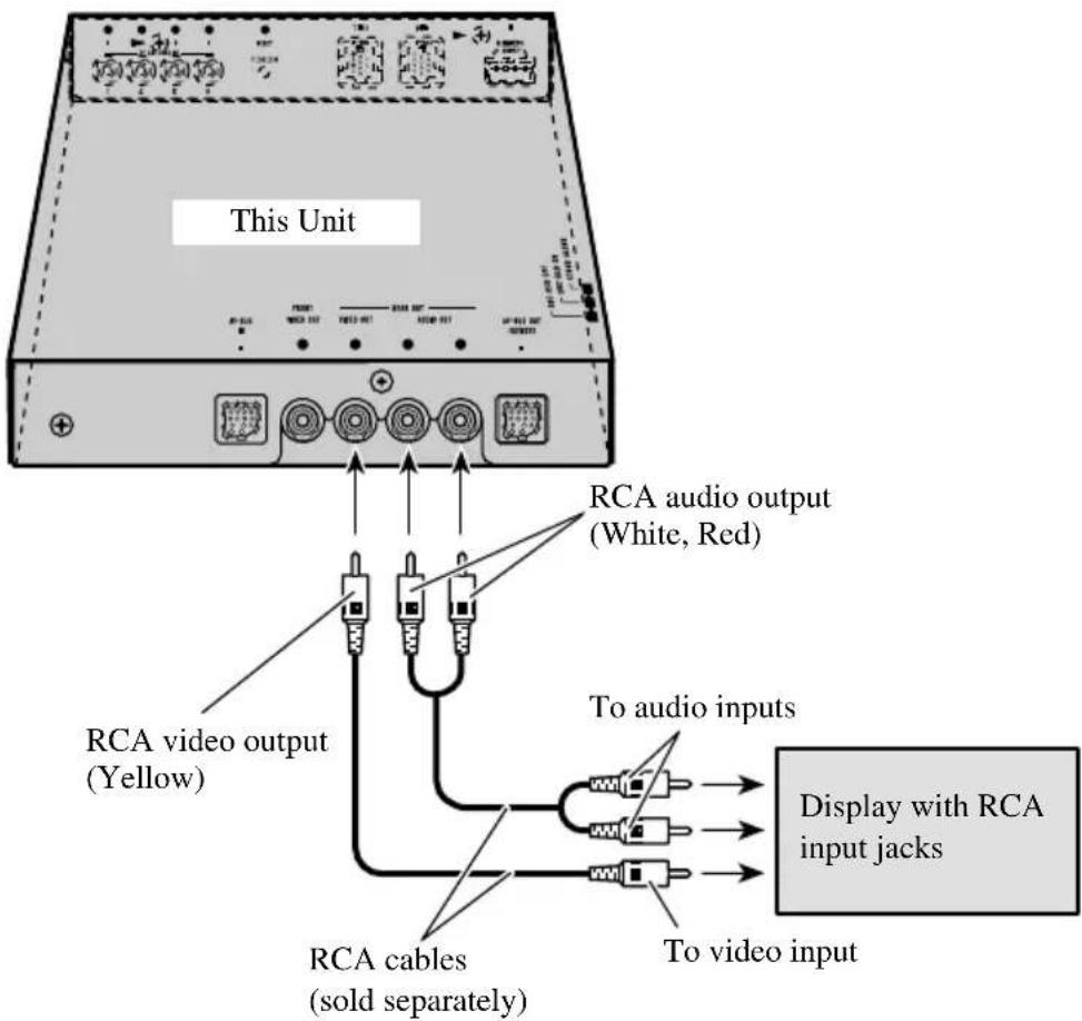
Installation
Note:
- Before making a final installation of the unit, temporarily connect the wiring to confirm that the connections are correct and the system works properly.
- Use only the parts included with the unit to ensure proper installation. The use of unauthorized parts can cause malfunctions.
- Consult with your nearest dealer if installation requires the drilling of holes or other modifications of the vehicle.
- Install the unit where it does not get in the driver's way and cannot injure the passenger if there is a sudden stop, like an emergency stop.
- When mounting this unit, make sure none of the leads are trapped between this unit and the surrounding metalwork or fittings.
- Do not mount this unit near the heater outlet, where it would be affected by heat, or near the doors, where rainwater might splash onto it. (Never install in locations such as the above because of the danger of malfunction due to high temperatures.)
- Before drilling any mounting holes always check behind where you want to drill the holes. Do not drill into the gas line, brake line, electrical wiring or other important parts.
- If this unit is installed in the passenger compartment, anchor it securely so it does not break free while the car is moving, and cause injury or an accident.
- If this unit is installed under a front seat, make sure it does not obstruct seat movement. Route all leads and cords carefully around the sliding mechanism so they do not get caught or pinched in the mechanism and cause a short circuit.
Switching the operation mode
Before installing, use a thin standard tip screwdriver to switch the operation mode switch on this unit to the appropriate position for the component you are using it with.

Installing the Unit
Adhere the hard Velcro tape (provided) to the bottom of the hide-away unit and adhere the soft Velcro tape (provided) to the installation location.
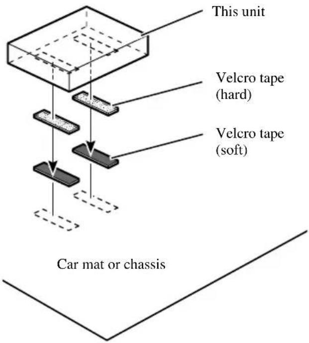
Note:
- Direct installation on the carpet is possible if the hard Velcro tape will adhere to the carpet. Do not use the soft Velcro tape in this case.
- Thoroughly wipe off the surface before affixing the velcro tape.
natural_image
Technical line drawing of a mechanical clamp or bracket assembly with a magnified inset showing internal components (no text or symbols)Einbau des Geräts
natural_image
Diagram of a mechanical assembly with arrows indicating direction (no text or symbols)PIONEER ELECTRONICS (USA) INC.
P.O. Box 1540, Long Beach, California 90801-1540, U.S.A.
TEL: (800) 421-1404
PIONEER EUROPE NV
Haven 1087, Keetberglaan 1, B-9120 Melsele, Belgium
TEL: (0) 3/570.05.11
PIONEER ELECTRONICS ASIACENTRE PTE. LTD.
253 Alexandra Road, #04-01, Singapore 159936
TEL: 65-6472-7555
PIONEER ELECTRONICS AUSTRALIA PTY. LTD.
178-184 Boundary Road, Braeside, Victoria 3195, Australia
TEL: (03) 9586-6300
PIONEER ELECTRONICS OF CANADA, INC.
300 Allstate Parkway, Markham, Ontario L3R OP2, Canada
TEL: 1-877-283-5901
PIONEER ELECTRONICS DE MEXICO, S.A. de C.V.
Blvd. Manuel Avila Camacho 138 10 piso
Col.Lomas de Chapultepec, Mexico, D.F. 11000
TEL: 55-9178-4270
先鋒股份有限公司
Published by Pioneer Corporation.
Copyright © 2005 by Pioneer Corporation.
All rights reserved.
Publication de Pioneer Corporation.
Copyright © 2005 Pioneer Corporation.

- Connecting the Units 1
- Installation 8
- Note:
- Power cable connection
- Yellow
- Red
- Connection method
- Light green
- When using this unit as "SRC : OSD OFF" mode
- AV-BUS cable
- When using this unit as "SRC : OSD ON" mode
- When using this unit as "STAND ALONE" mode
- TV antenna connection
- Connecting the Units
- Rear display connection
- Installation
- Switching the operation mode
- Installing the Unit
- Einbau des Geräts
- PIONEER ELECTRONICS (USA) INC.
- PIONEER EUROPE NV
- PIONEER ELECTRONICS ASIACENTRE PTE. LTD.
- PIONEER ELECTRONICS AUSTRALIA PTY. LTD.
- PIONEER ELECTRONICS OF CANADA, INC.
- PIONEER ELECTRONICS DE MEXICO, S.A. de C.V.
- 先鋒股份有限公司
Brand : PIONEER
Model : GEX-P5700TVP
Category : Digital decoder