USER MANUAL DRM-3000 PIONEER
Operating Instructions
Mode d'emploi
Bedienungsanleitung
操作说明书
取掇說明書
IMPORTANT
The lightning flash with arrowhead symbol, within an equilateral triangle, is intended to alert the user to the presence of uninsulated "dangerous voltage" within the product's enclosure that may be of sufficient magnitude to constitute a risk of electric shock to persons.
CAUTION
RISK OF ELECTRIC SHOCK DO NOT OPEN
CAUTION:
TO PREVENT THE RISK OF ELECTRIC SHOCK,DO NOT REMOVE COVER (OR BACK).NO USER-SERVICEABLE PARTS INSIDE.REFER SERVICING TO QUALIFIED SERVICE PERSONNEL.
The exclamation point within an equilateral triangle is intended to alert the user to the presence of important operating and maintenance (servicing) instructions in the literature accompanying the appliance.
H002 En
Replacement and mounting of an AC plug on the power supply cord of this unit should be performed only by qualified service personnel.
IMPORTANT
FOR USE IN THE UNITED KINGDOM.
The wires in this mains lead are coloured in accordance with the following code :
Green and Yellow : Earth
Neutral
Brown :Live
If the plug provided is unsuitable for your socket outlets, the plug must be cut off and a suitable plug fitted.
The cut-off plug should be disposed of and must not be inserted into any 13 amp socket as this can result in electric shock. The plug or adaptor or the distribution panel should be provided with 5 A fuse. As the colours of the wires in the mains lead of this appliance may not correspond with coloured markings identifying the terminals in your plug, proceed as follows;
The wire which is coloured green and yellow must be connected to the terminal in the plug which is marked with the letter E or by the earth symbol , or coloured green or green and yellow.
The wire which is coloured blue must be connected to the terminal which is marked with the letter N or coloured black.
The wire which is coloured brown must be connected to the terminal which is marked with the letter L or coloured red.
NOTE
After replacing or changing a fuse, the fuse cover in the plug must be replaced with a fuse cover which corresponds to the colour of the insert in the base of the plug or the word that is embossed on the base of the plug, and the appliance must not be used without a fuse cover. If lost replacement fuse covers can be obtained from: your dealer.
Only 5 A fuses approved by B.S.I. or A.S.T.A to B.S. 1362 should be used. H0048En
[FOR EUROPEAN AND U.K. MODELS]
CAUTION
This product contains a laser diode of higher class than 1. To ensure continued safety, do not remove any covers or attempt to gain access to the inside of the product.
Refer all servicing to qualified personnel.
The following caution label appears on your changer.
Location: rear of the changer
CLASS 1 LASER PRODUCT LASER KLASSE 1 APPAREIL À LASER DE CLASSE 1
WARNING!
CAUTION : USE OF CONTROLS OR ADJUSTMENTS OR PERFORMANCE OF PROCEDURES OTHER THAN THOSE SPECIFIED HEREIN MAY RESULT IN HAZARDOUS RADIATION EXPOSURE,
CAUTION : THE USE OF OPTICAL INSTRUMENTS WITH THIS PRODUCT WILL INCREASE EYE HAZARD.
H013 En
[For U.S. model]
CAUTION:
This product satisfies FCC regulations when shielded cables and connectors are used to connect the unit to other equipment. To prevent electromagnetic interference with electric appliances such as radios and televisions, use shielded cables and connectors for connections. H012 En
[For Canadian model]
This Class A digital apparatus complies with Canadian ICES-003.
This product complies with the Low Voltage Directive (73/23/EEC), EMC Directives (89/336/EEC, 92/31/EEC) and CE Marking Directive (93/68/EEC).
FOR FRANCE
Alteration or modifications carried out without appropriate authorization may invalidate the user's right to operate the equipment. H011En
FOR ENGLAND
Warning
This is a class A product. In a domestic environment this product may cause radio interference in which case the user may be required to take adequate measures.
FOR FRANCE
Attention
NOTE: This equipment has been tested and found to comply with the limits for a Class A digital device, pursuant to Part 15 of the FCC Rules. These limits are designed to provide reasonable protection against harmful interference when the equipment is operated in a commercial environment. This equipment generates, uses, and can radiate radio frequency energy and, if not installed and used in accordance with the instruction manual, may cause harmful interference to radio communications. Operation of this equipment in a residential area is likely to cause harmful interference in which case the user will be required to correct the interference at his own expense. H061En
[For Taiwanese model]
Handling the cord on this product or cords associated with accessories sold with the product will expose you to lead, a chemical known to the State of California and other governmental entities to cause cancer and birth defects or other reproductive harm.
Wash hands after handling
[For Korean model]
사용자相关内容 A级以上기主机 이 기지는edge무용으로 전자과recht配合목을 힠 기지이요일 기재가 출는 사용자는 이 썸을 majority해지 기다라머만')(에 odds 기재 출는구일해였을 때,(('(')('('('('('('('('('('('('('('('('('('('('('('('('('('('('('('('('('('('('('('('('('('('('('('('('('('('('('('('('('('('('('('('('('('('('('('('('('('('('('('('('('('('('('('('('('('('('('('('('('('('('("('('('('('('('('('('('('('('('('('('('('('('('('('('('('('('('('('('('('('('('('('('('('('('('('('('('('('('('('('('('('('('('('('('('('('('('('('('('('('('('('('('('('('('('('('('('('('('('('('('('='('('('('('('('('('('('('('('('('('('('('('('('('('('('('('('('('('('('('('('('('('('('('('('('('('('('('('('('('('('('('('('('('('('('('('('('('('('('('('('('('('('('('('('('('('('('('('('('('('('(')
H064A_Ko
IMPORTANT! SAFETY INSTRUCTIONS
READ INSTRUCTIONS - All the safety and operating instructions should be read before the appliance is operated.
RETAIN INSTRUCTIONS - The safety and operating instructions should be retained for future reference.
HEED WARNING - All warnings on the appliance and in the operating instructions should be adhered to.
FOLLOW INSTRUCTIONS - All operating and use instructions should be followed.
CLEANING - Unplug this product from the wall outlet before cleaning.
WATER AND MOISTURE - Do not use this product near water
ACCESSORIES - Do not place this product on an unstable cart, stand, or table. The product may fall and be seriously damaged.
VENTILATION - Slots and openings in the cabinet and back or bottom are provided for ventilation and to ensure reliable operation of the product and to protect it from overheating. These openings must not be blocked or covered. They should never be blocked by placing the product on a bed, sofa, rug, or other similar surface. This product should never be placed in a built-in installation unless proper ventilation is provided.
POWER SOURCES - This product should be operated only from the type of power source indicated on the marking label. If you are not sure of the type of power available, consult your dealer or local power company.
PLUG - This product is equipped with a wired grounding-type plug (a plug having a third (grounding) pin). This plug will only fit into a grounding type power outlet. This is a safety feature. If you are unable to insert the plug fully into the outlet, contact your electrician to replace your obsolete outlet. Do not defeat the safety purpose of the grounding type plug.
16. DAMAGE REQUIRING SERVICE
POWER-CORD PROTECTION - When unplugging the apparatus, pull on the plug - not on the cord. Do not handle the cord on plug with wet hands. Doing so could cause an electric short or shock. Do not allow anything to rest on the power cord. Do not locate this product where persons will walk on the cord.
OVERLOADING - Do not overload wall outlets and extension cords as this can result in fire or electric shock.
OBJECT AND LIQUID ENTRY - Never push objects of any kind into this product through openings as they may touch dangerous voltage points or short out parts that could result in a fire or electric shock. Never spill liquid of any kind on the product.
CONDENSATION - Moisture will form in the operating section of the product and the product's performance will be impaired if the product is brought from cool surroundings into a warm room or if the room temperature rises suddenly. To prevent this, let the product stand in its new surroundings for about an hour or two before switching it on, or ensure that the room temperature rises gradually.
SERVICING - Do not attempt to service this product yourself as opening or removing covers may expose you to dangerous voltage or other hazards. Refer all servicing to qualified service personnel.
Unplug this product from the wall outlet and refer servicing to qualified service personnel under the following conditions:
a. When the power cord or plug is damaged.
WARNING: THE APPARATUS IS NOT WATERPROOFS, TO PREVENT FIRE OR SHOCK HAZARD, DO NOT EXPOSE THIS APPARATUS TO RAIN OR MOISTURE AND DO NOT PUT ANY WATER SOURCE NEAR THIS APPARATUS, SUCH AS VASE, FLOWER POT, COSMETICCS CONTAINER AND MEDICINE BOTTLE ETC. H001BEn
WARNING: THIS PRODUCT EQUIPPED WITH A THREE-WIRE GROUNDING (EARTHING) TYPE PLUG, A PLUG HAVING A THIRD (GROUNDING, EARTHING) PIN, IT WILL ONLY FIT INTO A GROUNDING (EARTHING) TYPE POWER OUTLET. THIS IS A SAFETY FEATURE. IF YOU ARE UNABLE TO INSERT THE PLUG INTO THE OUTLET, CONTACT YOUR ELECTRICIAN TO REPLACE YOUR OBSOLETE OUTLET. DO NOT DEFECT THE SAFETY PURPOSE OF THE GROUNDING (EARTHING) TYPE PLUG. H043A En
Operating Environment
H045 En
Operating environment temperature and humidity:
+5°C - +35°C (+41°F - +95°F); less than 85%RH (cooling vents not blocked)
Do not install in the following locations
[For Australian and New Zealander models]
Warning
This is a class A product. In a domestic environment, this product may cause radio interference in which case the user may be required to take adequate measure. H062A Er
For pluggable Equipment, The Socket-Outlet Shall Be Installed Near The Equipment and Shall Be Easily Accessible.
The Generation of Acoustical Noise Is Less Than 70 dB. (ISO 7779/DIN45635)
Thank you for buying this Pioneer product.
Please read through these operating instructions so you will know how to operate your model properly. After you have finished reading the instructions, put them away in a safe place for future reference.
In some countries or regions, the shape of the power plug and power outlet may sometimes differ from that shown in the explanatory drawings. However, the method of connecting and operating the unit is the same.
CONTENTS
FEATURES 5
HANDLING PRECAUTIONS 6
READ BEFORE USE 7
Security features 7
TO AVOID PROBLEMS 12
NAMES AND FUNCTIONS OF
INDIVIDUAL PARTS 14
INSTALLATION 16
OPERATION 24
User mode 24
OTHERS 44
Troubleshooting 44
Specifications 46
FLEXIBLE UNIT DESIGN
The Pioneer DRM-7000/DRM-3000-disc changer is designed so that a variety of different components may be purchased and installed together to meet a variety of different needs.
The Pioneer DRM-7000/DRM-3000 comes with bays (i.e., spaces for the installation of drives or 50-disc magazines) located at the front and rear of the unit, and the bays are fitted with access doors that are designed to open widely and enable you to install or remove individual components with ease.
The front bay is for exclusive use with 50-disc magazines; the rear bay has been designed as a multi-purpose installation area:
Loading Capacity
DRM-7000 DRM-3000 Front bay 50-disc magazines only 7 3 Rear bay Component Max 16 Max 8 50-disc magazines Max 7 Max 3
The maximum number of optional components that can be installed differs depending on the component involved; for details, consult the operating instructions for your option components.
Combined Example
DRM-7000 DRM-3000 Data capacity emphasis Drives 2 Drives 2 Discs 720 Discs 320 Performance emphasis Drives 16 Drives 8 Discs 370 Discs 170
If desired, you can start with empty bay spaces and add devices to them as your requirements increase.
THREE DIFFERENT TYPES OF DISC MAGAZINES EQUIPPED WITH INTERNAL MEMORY
Pioneer provides three different types of disc magazines designed for convenience and ease of use in different applications.
20-disc hyper magazine:
The main feature of the hyper magazine is its mobility. It can be inserted and removed without opening the access door. Another feature is a smart memory system that records all user operations toward its lock/unlock mechanism. One hyper magazine is provided as a standard equipment with each Pioneer DRM-7000/DRM-3000.
50-disc magazine (locked-type):
This model is perfect for managing offline media where the security and unchangeableness may be required. Built-in locking mechanism makes it impossible to remove discs from magazine whenever it is outside the changer.
50-disc magazine (normal-type):
This model is convenient for importing or exporting large volumes of discs into or from the changer. You can insert discs into or remove them from a magazine releasing the locking mechanism by a knob fitted with this magazine when it is outside the changer.
EASE OF INSTALLATION
In order to connect the changer to an existing data management system or to build a new data management system, it is necessary for the host computer to be able to properly identify the changer and all the drives contained therein and it is necessary to attach all the cables and specify the settings needed for the host computer to control the changer and drives.
The Pioneer DRM-7000/DRM-3000 is designed not only to make it easy to install and add new drives, but also with a wide range of features designed to make it easier to specify host computer settings.
SECURITY FEATURES DESIGNED TO PREVENT ERRONEOUS OR UNAUTHORIZED OPERATIONS
In order to prevent interference, conflicts, or clashes occurring between manual operations and computer-based operations, entering procedure to the system administrator mode is introduced. Anyone who wants to perform operations from the control panel is required to enter system administrator mode first, using the provided lock release key. And it is possible to prevent the switchover to some sub-modes by issuing a command from the host computer.
It is also possible to assign security privileges on the system administrator who has the lock release key. Then operations directly manipulating discs, like opening mailslot and ejecting hyper magazine, are permitted to only the system administrator.
CONTROL PANEL FITTED WITH AN LCDMESSAGE WINDOW FOR EASE OF USE
The control panel is fitted with a 2-line, 16-column LCD message window which is used to display instructions on the proper operations to perform. And this makes it possible to perform any of the wide variety of different operations provided by the DRM-7000/DRM-3000 with only 5 keys.
INSTALLATION
Select an installation site with a flat, solid surface.
Do not install the system where it will suffer any of the following:
① Exposure to direct sunlight or a heater
(If the surface is not flat, first put down a hard plate or similar support so that the system is installed level.)
⑦ Difficulty of service and maintenance.
If the changer is to be installed next to a wall, a minimum of at least 50~cm of space must be provided between the back of the changer and the wall.
Avoid placing objects directly on the changer.
HANDLING PRECAUTIONS
Be careful not to stain, scratch or leave fingerprint, etc., on the signal surface, or recording surface of the discs. The specified playback performance or recording performance may not be obtained with such discs.
Do not insert more than one disc in a mailslot, otherwise malfunction will result.
The Changer does not manage the disc contents. The data should be managed by involving the host.
Use only recording discs recommended by Pioneer. The specified recording performance or playback performance may not be obtained if a non-recommended disc is used. Please note that the data recorded on discs is not covered by our warranty.
Pioneer may not be held liable for the loss of any data or any other direct or indirect damage suffered as the result of the use or breakdown of this product. It is strongly recommended that regular backups be taken of all critical data.
Please be careful not to lose the lock release keys provided with your DRM-7000/DRM-3000, otherwise you could not manage your changer any more. The lock release key certifies you as a system administrator and gives you a privilege to open access doors, to eject a hyper magazine and to use a mailslot.
POWER-CORD CAUTION
Handle the power cord by the plug. Do not pull out the plug by tugging the cord and never touch the power cord when your hands are wet as this could cause a short circuit or an electric shock. Do not place the unit, a piece of furniture, etc., on the power cord, or pinch the cord. Never make a knot in the cord or tie it with other cords. The power cords should be routed such that they are not likely to be stepped on. A damaged power cord can cause a fire or give you an electrical shock. Check the power cord once in a while. When you find it damaged, ask your nearest PIONEER authorized service center or your dealer for a replacement.
FOR SAFETY
Do not install the unit on any unsteady platform or desk, etc., as the unit is tall and heavy.
Do not stack the units or do not place a heavy object on the unit. It is extremely dangerous to do this, because the objects may fall off or the unit may topple over. (Any damage or injury suffered as a result of such installation is the sole responsibility of the user.)
Attach the placement fixtures first after unpacking the changer. If it is moved before they are attached, there is a danger of it toppling over or of the cables on the rear being damaged.
Always be sure not to insert your hand into the 20-disc hyper magazine bay or not to touch any parts inside of the bay when the power has been turned on, otherwise it may result in bodily injury.
The Changer can accommodate only the discs with a diameter of 12cm (5in). As the Changer detects the presence of disc with optical detection of the position at about 5mm (3/16in) inside the external periphery of the 12cm (5in) disc, the use of a disc which is transparent at the corresponding position or a 8cm (3in) disc may lead to disc detection error and to the disc damage in the worst case. Also, the use of a 8cm disc adapter is strictly prohibited.
For safety reasons, the DRM-7000/DRM-3000 is designed so that the access doors cannot be opened while the changer mechanism or internal drives are in operation.
The high speed rotation of discs or the operation of the high speed disc transport mechanism in the DRM-7000/DRM-3000 causes slight vibrations and noise, but this does not indicate a problem. And it does not effect the performance of the changer.
CONDENSATION
If the temperature difference between the changer and environment is too large, water will condense in the changer and the system may not provide proper performance. For example, if you bring the changer into a warm room from outside in cold weather, or if you increase room temperature abruptly, condensation may result. If condensation occurs, leave the changer for one hour in the room, or increase room temperature gradually before using it.
CLEANING THE CHANGER
To clean the panel and the cover, use a soft, dry cloth to wipe off dust and dirt. If the cabinet is heavily soiled, wipe off the dirt using a soft cloth soaked with neutral detergent diluted 5 to 6 times. Then wipe the water off with a dry cloth. Do not use benzine, thinner, insecticide or similar volatile chemicals, as they may dissolve or discolor the cabinet surface. If you use a chemical polishing cloth, carefully read the instructions supplied with it.
SECURITY FEATURES
Information on the location of discs within the changer and information to access data on discs are strictly monitored and controlled from the changer control software and the upper-level database management software.
Because of this, if any changes in the status of the discs within the changer occur at a time when the changer is not under the control of the host computer (or in a network environment, under the control of a server), it becomes impossible to control the changer and drives and to read necessary files from discs.
Allowing discs stored within the changer to be removed without any restrictions poses a security risk, not only in that it would become impossible to access discs which have been removed but also in that it might lead to the damage or loss of discs.
Although the DRM-7000/DRM-3000 has been designed so as to open the front and rear access doors from the control panel (located at the top of the front of the unit) to remove magazines or to insert or remove discs through the mailslots, anyone who considers the security issues noted above will be able to understood that it is necessary to place restrictions on such operations.
This is why the control panel of the DRM-7000/DRM-3000 has been fitted with a key switch which may be locked to disable operations of control keys. This switch cannot be unlocked without the key provided with the DRM-7000/DRM-3000, and if the system administrator will always keep this key, it is impossible that ordinary users without key perform unauthorized operations from the control panel.
It is also possible to restrict the range of operations which are performed from the control panel. It means that a part of system administrator's privileges is controlled by the command issued from the host computer and even if a system administrator has the key, the host computer makes it impossible to open the access doors, exchange discs, or perform other unfavorable operations for itself.
The DRM-7000/DRM-3000 provides the following features which makes it perfect for the management of offline media.
- Removable disc magazines
Disc magazines may be removed from the changer with the discs left in the magazines. The use efficiency of the space within the changer may much improve if the infrequently used discs are collected in one magazine and it is taken out from the changer into the offline storage.
- Unique disc magazine IDs
All disc magazines used in the DRM-7000/DRM-3000 are assigned unique ID codes which makes it possible to identify individual magazines simply by inserting them into the magazine bays.
All of the discs within an inserted magazine become available immediately no matter which magazine bay it is inserted into as long as the discs installed in the magazine have been registered in the database as corresponding to the magazine ID in question, and the same holds true when a magazine is inserted into a different changer as long as the changer in which it is inserted is under the control of the same database.
- Disc magazines designed for easy tracking and control
Removing, inserting or replacing discs in magazines after they have been removed from a changer may destroy the correspondence between discs and magazine IDs.
To solve this problem, Pioneer provides 50-disc magazine which has a locking mechanism to prevent all attempt to change the status of the magazine outside the changer and hyper magazine which has a smart memory system that records all user operations toward its lock/unlock mechanism so as to make it easier to track and control the use of offline media.
- Registration of changer ID
When a disc magazine has been inserted into a changer not under the control of the database management software or into a changer belonging to another system, the discs within that magazine may be rewritten or may be replaced with other discs within that changer. Even if the magazine in question is a locked-type, these discrepancies between the discs actually contained within the magazine and the information on those discs stored in the database may be arise.
In order to prevent such problems from occurring, disc magazines are designed to record the ID of the changer in which they are used, and as long as the database has a list of the IDs of changers controlled under the given database, it is possible for the database management software to determine whether or not a inserted disc magazine has to be reinstalled by checking the changer ID that may be read with the magazine ID.
However although the DRM-7000/DRM-3000 changer and disc magazines do provide the features needed for the management of offline media, it should be noted that the actual procedures and methods available for the management of offline media may differ depending on the database management software and changer control software being used.
It should further be noted that it is necessary to establish how to employ controls for the handling of offline media. In fact if management controls are strict enough, it is even possible to use normal-type disc magazines which would ordinarily be unsuited for use in the management of offline media, in the same way as one would use locked-type disc magazines.
DECIDING ON SYSTEM CONFIGURATION
Before installing or using the changer, the first thing which has to be done is to decide what components you should install to where of the changer.
The connector panel and SCSI cables which come with the DRM-7000/DRM-3000 are prepared on the assumption of the following system configuration:
Two drives
(Note that it is also necessary to purchase another SCSI cable to connect the changer to the host computer when the DRM-7000/DRM-3000 is to be used in the above configuration.)
If you wish to install three or more drives or to use more than one SCSI bus to increase data transfer speeds, it will be necessary to purchase additional connector panels and SCSI cables.
To determine what additional equipment must be purchased in order to create a desired configuration, it is recommended that you first decide where drives are to be installed and consult the configuration sheet on p. 225 (DRM-7000) or p. 226 (DRM-3000) before actually trying to configure your system.
Before actually beginning to configure your changer system, it is absolutely necessary that the following items be determined:
The types and numbers of drives to be installed and where they are to be installed. (An additional power unit is necessary when installing 9 or more drives on the DRM-7000).
The positions where connector panels are to be attached. (Note that the DRM-7000/DRM-3000 comes equipped with a multi drive connector panel and if you need single drive connector panels you must purchase them.)
The SCSI IDs to be assigned to each of the drives to be installed. (Note that it is impossible to assign the same SCSI ID to two or more drives on the same SCSI bus.)
The connecting plan of the cables running between individual drives and connector panels.
Which drives are to be terminated (i.e., the drive's termination switch of the terminal drive in each SCSI chain is to be turned on).
An example of how SCSI cables should be connected is shown on p. 19.
The power unit provided as standard equipment is capable of supplying power to rear bays #1 - 8. The total power consumed by these eight drives should not exceed the following:
DC +5 V 12 A or less
DC +12 V 8 A or less
The maximum current capacity of a single connector is as follows:
DC +5 V Max 4 A
DC +12 V Max 4 A
By adding an optional expansion power unit to the DRM-7000, power can be supplied to rear bays #9 - 16.
The maximum power consumption of these upper bays and the maximum amount of power which may be supplied over a single connector is the same as that of the lower bays (i.e., Bay #1 - Bay #8).
NOTE:
Be sure never to use any add-on products other than Pioneer products.
When turning off the power and turning it back on, always be sure to allow an interval of 10 seconds or more to elapse after turning off the power before turning it back on. Note that this must be done because there are times when the power is not switched off immediately even after the power switched has been flipped off when few drives have been installed in the changer.
ADD-ON PRODUCTS
The following components may be purchased separately for use with the Pioneer DRM-7000/DRM-3000 in order to adapt it for use in configuring a system to your own specifications. The maximum number of optional components that can be installed differs depending on the component involved; for details, consult the operating instructions for your option components.
50-disc magazine
Used to store discs within the changer, these magazines come in both normal and locked types which can be installed in whatever combination best fits your needs.
These disc magazines are designed so that the lock is not released even when a magazine is removed from a changer. Therefore the mailslot is necessary to insert discs into these magazines or remove discs from them. These magazines are extremely effective for use in situations where they are used in combination with a host computer which supports offline media management. (See p. 7 for further details.)
Fitted with a knob which is used to release the locking mechanism, these magazines are convenient for importing or exporting large volumes of discs into or from the changer.
This magazine is designed to make it possible to insert or remove without opening the access doors. This magazine is also equipped with a smart memory system that records all user operations toward its lock/unlock mechanism. Therefore the hyper magazine is convenient and also perfect for the management of offline media. The DRM-7000/DRM-3000 comes with a hyper magazine as a standard equipment, and additional hyper magazines may be used to easily build up an offline library in 20-disc units.
DVD-R/RW drive unit [DVD-R7322]
Power consumption: DC +5V, 1.5A
DC +12V, 1.0A
The DVD-R7322 internal DVD-R/RW drive unit may be used both to read ordinary DVD-ROM discs and to read from and write to DVD-R/RW discs.
DVD-ROM drive unit [DVD-D7563]
Power consumption: DC +5V, 1.0A
DC +12V, 1.0A
The DVD-D7563 internal DVD-ROM drive unit may be used to read DVD-ROM discs.
The DRM-UF701 disc flip unit is designed for use in turning over a disc. Note that this component is required when using double-sided DVD discs.
Power supply unit [DRM-PW701] (for DRM-7000)
A DRM-PW701 add-on power supply unit must be installed in order to use 9 or more drives within the same changer.
Always be sure to contact Pioneer service personnel for installation.
Power supply: Maximum of DC +5V, 12A
Maximum of DC +12V, 8A
Malti drive connector panel [DRM-SN721]
The DRM-SN721 multi drive connector panel comes with a cable which may be used to connect two internal drives.
The DRM-7000/DRM-3000 comes with a DRM-SN721 panel as a standard equipment, and this panel may be used to connect 2 or 4 additional drives in a daisy chain.
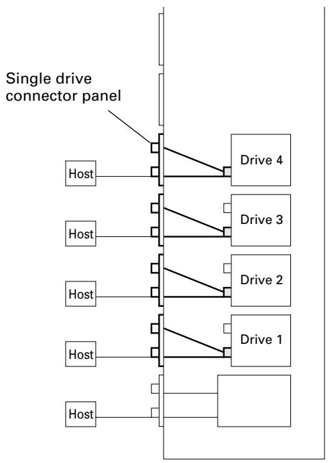
Single drive connector panel [DRM-SN711]
The DRM-SN711 single drive connector panel is used when a drive is to be connected directly to a host computer or when drives are to be daisy-chained outside of the changer unit.
Cable for 2 drives [DRM-SC721]
The DRM-SC721 2-drive SCSI cable is designed for internal daisy-chain connection to additional two drives. When used in combination with the DRM-SN721 multi drive connector panel, this cable makes it possible to connect up to 4 internal drives.
Cable for 4 drives [DRM-SC741]
The DRM- SC741 4-drive SCSI cable is designed for internal daisy-chain connection to additional four drives. When used in combination with the DRM-SN721 multi drive connector panel, this cable makes it possible to connect up to 6 internal drives.
ITEMS INCLUDED
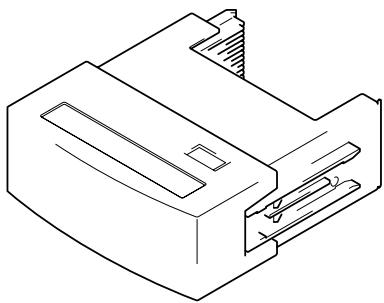
20-disc hyper magazine ... 1
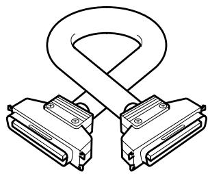
Changer/drive SCSI cable … 1
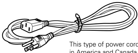
Power cord (for Canada and the U.S.) ... 1
This type of power cord is for use in America and Canada only.
Do not use this power cord in places other than America or Canada.
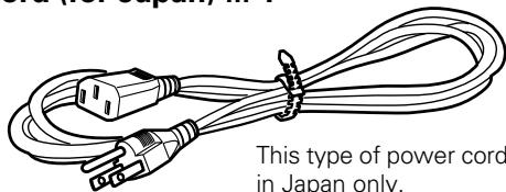
Power cord (for Japan) ... 1
This type of power cord is for use in Japan only.
Do not use this power cord in a places other than Japan.
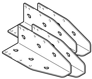
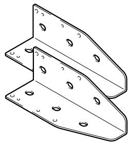
Base stabilizer
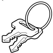
Lock release key ... 2
Screw for use in attaching base stabilizers
DRM-7000 ... 12
DRM-3000 ... 6
Operating instructions ... 1
DISCS
Discs which may be used with the Pioneer DRM-7000/DRM-3000
The types of discs which may be used with the Pioneer DRM-7000/DRM-3000 vary depending on the types of drives being used, and for further information on the types of discs which may be used you should accordingly consult the operating instructions provided with your drive units.
Handling the discs
Avoid touching the signal surface when you use a disc.
To hold it, place your fingers on the edge of the disc or the edge of the center hole and the disc edge.
Do not attach paper or stickers to the label side of the disc. Handle discs carefully and avoid damaging the label.
Discs rotate at high speed in the changer. Do not use defective discs (e.g., cracked or considerably warped). Such discs may damage the changer.
DO NOT use non-standard discs, as these may adversely influence this unit and other equipment.
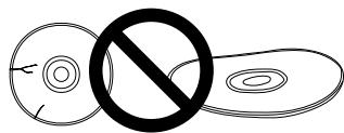
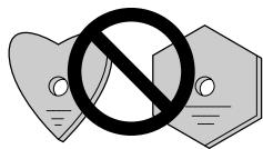
DO NOT play a CD having other shape than a circular disc, such as heart shaped disc, or malfunction may occur.
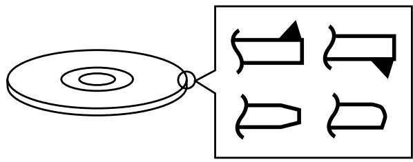
Do not use the following types of discs for they may cause malfunction of the unit or damage to the discs:
Disc which has a molding flash (projected fin) left on the periphery as shown in the illustration.
Disc with its edges are rounded or tapered as shown in the figure.
The following is a list of operation items that may potentially lead to problems in component functioning.
Issue Potential Malfunction/Error 1. Installation Do not place foreign objects inside the changer, since malfunction may result. [E83], [E99], [E88] Do not use the changer in locations subject to high concentrations of dust, heat, or humidity.
* Do not install in locations directly exposed to outdoor dust or air.
* Do not install near air conditioner vents or air cleaners. Recording/playback mal-function Do not subject the recorder to impact or vibration during use.
* Do not install in hallways or other areas near frequent pedestrian traffic. Recording/playback mal-function 2. Connections When connecting exterior SCSI cable, be sure that power is first turned off to host computer and changer.
* When connecting internal SCSI cable, power may be left while connecting. Changer malfunction When installing a drive, be sure to connect the changer interface cable to the connector corresponding to the bay in which the drive is installed. If the cable is mistakenly connected to a neighboring connector, the discs may be damaged and the E99 error may occur. [E83], [E99] Be sure to set the terminator switch to ON on the final component connected to the SCSI bus. If it is mistakenly set to OFF, the changer operation may be unstable. If malfunctions occur with the switch set to OFF, set the switch to ON and turn the power on again.
* When a component's terminator switch is set to ON, if the component is subsequently removed from the SCSI bus, or if the component's SCSI cable is disconnected, the condition immediately reverts to the same state as when the terminator is OFF, thus resulting in the same condition as above. Display window (LCD) doesn't appear correctly.
Operation keys malfunction.
Changer not recognized on the SCSI. When installing a drive, if the wiring monitor indicator does not flash, recheck and install the power cable connection, followed by the changer interface connection. Changer does not detect drive. 3. Power ON/OFF Never disconnect power while the changer is transporting a disc, or when the writer is recording data to a disc. Changer malfunction.
Data recording malfunction When turning the power off and then on again, wait at least ten seconds after turning the power off before turning it on again. 4. Control During data recording, do not send commands from the disc writer to remove disc (Move Medium, Rezero Unit), since EC* error or write malfunction may occur (back buffer overrun). Recording malfunction
[EC*], (where * = 0 - F) 5. Transporting Unit When transporting the unit, pack the unit in its original packaging materials, and ship in an upright position. Do not transport the unit on its side. Do not transport the unit with drive units, 50-disc magazines or other optional accessories loaded (except for 20-disc hyper-magazine). When transporting the accessories, repack them in their original packaging materials. Do not transport disc magazines with discs loaded. 6. Error Correction E8*, E9*, EF8, or EF3 errors cannot be corrected merely by resetting the changer's power on/off. The system administrator mode must be used to open and then close the door again. For these and other errors, see the Operating Instructions, p. 44. [E8*], [E9*], [EF8], [EF3] (where * = 0 - F) 7. Discs ·Blank discs, discs which have experienced failed recording operations, and discs whose recording sessions have not been closed, cannot be used on the reader drive.
* Use the writer drive to determine whether a disc is blank. ·Reader drive malfunction
[Set Up NG] error ·Do not affix paper labels or seals to discs. Also, do not allow the printed surface of discs to become scratched.
* If a paper label is removed incorrectly, it may leave behind pieces of adhesive that cause player malfunction; as a result, when removing an adhesive label, be sure to remove it carefully and fully, taking care not to leave an scratches on the surface of the disc. ·Recording/playback mal-function
[E83], [E99] ·Scratches, fingerprints, or dirt adhering to the surface of a disc may interfere with recording or playback. When handling discs, take care not to touch the signal surface (the reflective recording surface). Hold discs either by the outside edges, or by placing a finger in the center hole. ·Recording/playback mal-function ·If a disc is soiled, wipe gently with a soft cloth in a radial direction, straight from the center outwards. Do not wipe in a circular pattern.
* Use only the Pioneer Cleaning Cloth (Service Parts GED-009) for wiping discs. ·Recording/playback mal-function ·To produce stable recording and playback, use only recommended discs. For recommended discs, consult your dealer or Pioneer's website. ·Recording/playback mal-function ·This component does not support DVD-R for Authoring media. ·Cannot record 8. Disc Magazines ·When inserting discs in magazines, be sure they are inserted flat into the same slot; discs may be damaged if inserted diagonally (with left and right edges in differing slots). [E83], [E99] ·Do not allow the open end of magazines to point downward, since discs may fall out. [E83] ·Insert magazines slowly into the changer, since discs may fly fall out if the magazine is inserted with excessive force.
* When inserting a magazine, if the electronic buzzer sounds or error [E83 disc set NG] appears in the display, remove the maga-zine, press any dislodged discs back into the magazine, and slowly insert the magazine once again. [E83] 9. Disc Reversal Unit ·When the Pioneer Disc Flip Module DRM-UF701 is used in conjunction with the changer DRM-7000, the changer must be equipped with firmware Rev. 1.12 or later. Since malfunctions or disc damage may occur when used with firmware revisions earlier than 1.12, be sure to update your firmware before use to version 1.12 or later. For details regarding updating of firmware, consult your Pioneer service center, or retail dealer.
* The DRM-3000 module is not limited by firmware revisions. [EC*], (where *= 0 - F)
Other malfunctions
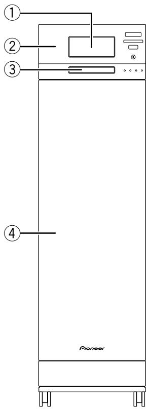
FRONT
FRONT ACCESS DOOR INSIDE
① 20-disc hyper magazine
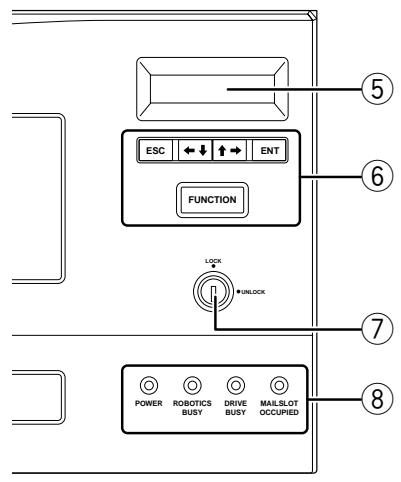
The backlight to the LCD message window is designed to automatically go into energy saving mode whenever more than 1 minute passes without any operations being performed from the control panel.
⑥ Operation keys
These keys are used to change the display items on the LCD message window and to select setting fields or values. Note that a lock release key is required in order to become effective these keys.
Escape key (ESC):
The escape key is used to step back from the message layer currently being displayed (i.e., to return to the previous display) or to halt operations.
This key is used to decrement displayed values or to move the display cursor down or to the left.
This key is used to increment displayed values or to move the display cursor up or to the right.
Enter key (ENT):
The enter key is used to step forward from the message layer currently being displayed or to initiate a specified operation.
Function key (FUNCTION):
The function key must be pressed in order to enter the system administrator mode.
⑦ Lock/Unlock key switch
Inserting a lock release key into this switch and rotating it 90 degrees releases the operation lock and makes it possible to perform operations from the control panel.
⑧ Status indicators
POWER:
This indicator lights up whenever the power is on.
ROBOTICS BUSY:
This indicator lights up whenever a disc transport mechanism is in operation.
DRIVE BUSY:
This indicator lights up whenever one or more discs are being placed on each drives.
MAILSLOT OCCUPIED:
This indicator lights up whenever a disc is placed in the closed mailslot.
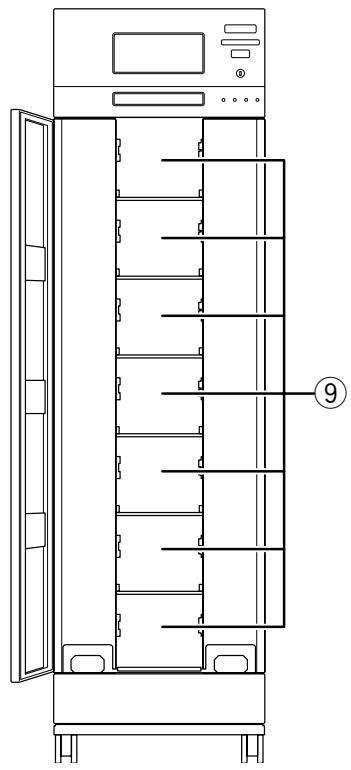
⑨ Front bays
DRM-7000
For use with disc magazines: M1 - M7
DRM-3000
For use with disc magazines: M1 - M3
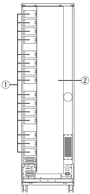
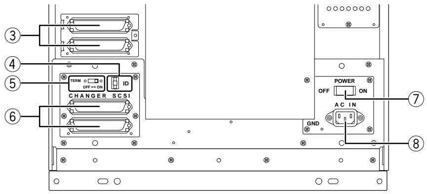
REAR
REAR ACCESS DOOR INSIDE
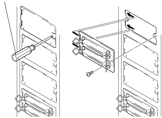
① Rear plates
These plates cover the space for attaching the connector panels.
② Rear access door
③ Drive SCSI ports (attached connector panel)
④ SCSI ID switch (ID)
This switch is used to assign the changer SCSI ID. If you would like to decrement the displayed SCSI ID, push the small switch just above the numeric display by a nib. And if you would like to increment, push the small switch just below the numeric display. Note that SCSI ID is set to '6' at the time of shipment.
⑤ SCSI termination switch (TERM)
This switch is for SCSI termination. Note that this switch is set ON at the time of shipment and it must be kept ON during the changer installation. But when the SCSI bus connection is completed and the changer is not the last device on the SCSI bus, it must be set OFF certainly.
⑥ Changer SCSI ports (CHANGER SCSI)
⑦ Power switch (POWER)
This switch is used to turn the power to the changer on and off.
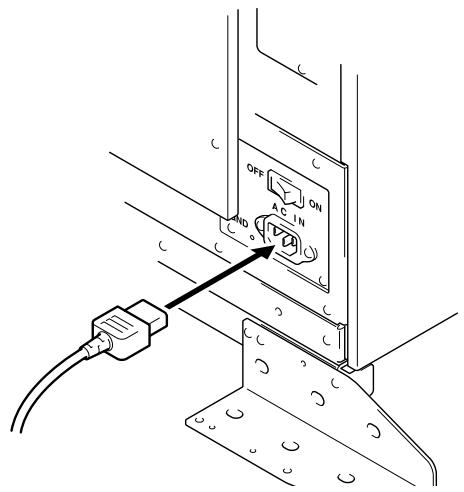
⑧ Power inlet (AC IN)
The power cord is inserted into this power inlet. (Note that you should always be sure to use only the power cord provided with your changer.)
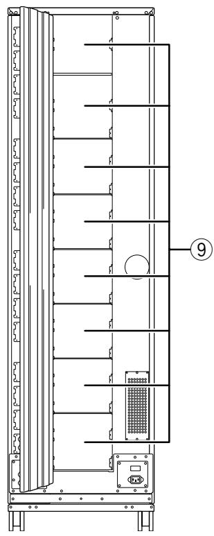
⑨ Rear bays
DRM-7000
For use with disc magazines: M8 - M15
For use with optional units/modules: Bays #1-16 DRM-3000
For use with disc magazines: M4 - M7
For use with optional units/modules: Bays #1-8
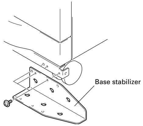
STEP1
1. Attach the base stabilizers.
To prevent the unit from falling over, be sure to attach the accessory base stabilizers. The DRM-7000 is provided with four stabilizers (one at each corner), and the DRM3000 is provided with two (rear corners only).
NOTES:
Be sure to attach the base stabilizers before doing anything else.
Note that the base stabilizers also serve to protect the ports and cables on the rear of the unit.
Note that any damage incurred as a result of the unit falling over or any damage caused to the rear ports or cables as a result of a failure to install the base stabilizers will not be covered under warranty.
In the case of the DRM-3000, be sure to attach the stabilizers only to the rear corners of the unit.
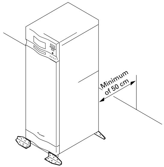
2. Deciding on the location where the changer is to be installed
The changer is designed with a rear access door which can be opened in inserting or removing drives or disc magazines, and the location where the changer is to be installed should be chosen so as to allow a minimum of 50cm of space between the rear of the changer and the nearest wall so as to leave enough room to open the rear access door and insert or remove drives or disc magazines.
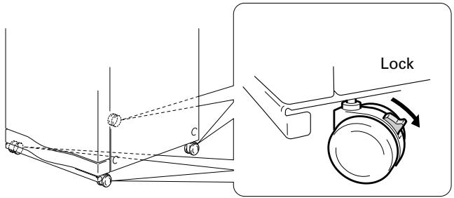
3. Lock the casters
Four casters at the bottom of DRM-7000/DRM-3000 allow it to be moved lightly but they must be locked soon if you place the changer on the chosen location. A caster is locked by lowering its lever.
4. Connect power cord
Insert the power cord into the power inlet on the rear of the changer and then insert the plug into a wall power outlet.
NOTE:
Always be sure to use only the power cord supplied with your changer.
Also be sure to follow the instructions on the label on the package and use only that cord designed for use in the location in which the power cord is to be used.
STEP2
Readying the changer for operation
In order to ready the changer for operation, perform the following steps in the order indicated.
Turning on the power (see p. 17)
Loosening the shipping screws (see p. 17)
Installing drive units (see p. 17)
Connecting SCSI cables (see p. 18)
Inserting disc magazines (see p. 20)
Closing access doors (see p. 23)
1. Turning on the power
When the power is first turned on, both the front and rear access doors will automatically open. This is not a faulty operation but the function of the shipping screws tightened at the time of shipping or re-transporting.
NOTES:
Be sure not to close neither the front nor rear access door until all drives and disc magazines have been installed.
If the door does not open when the power is turned on, wait until the initialization routine has completed and the LCD shows the user mode display (p. 23), then refer to p. 37 ("System Administrator Mode: Door Sub-mode") for instructions on opening the door.
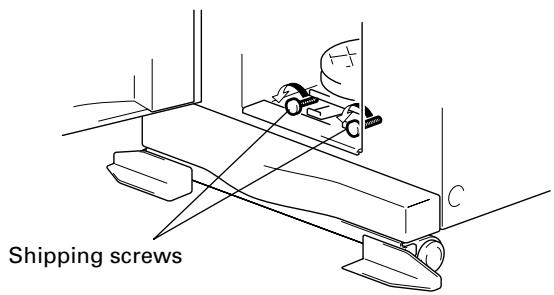
2. Loosening the shipping screws
When the front access door is opened, shipping screws may be seen at near the bottom inside the changer. These screws are attached to prevent damage to the built-in mechanism of the changer during transporting.
Shipping screws are designed so that they can only be loosened and cannot be removed so as to prevent their
becoming lost.
NOTES:
Be sure to tighten again the shipping screws before retransporting the changer.
If you or someone close the front or the rear access door with the shipping screws loosened, the closed door can not open automatically like before. And when the both doors are closed, the changer starts its mechanical initialization. So if you have not finished the installation yet, it is necessary to open the access doors again to continue with installation. (See System administrator mode: Door submodes on p. 37 for further information.)
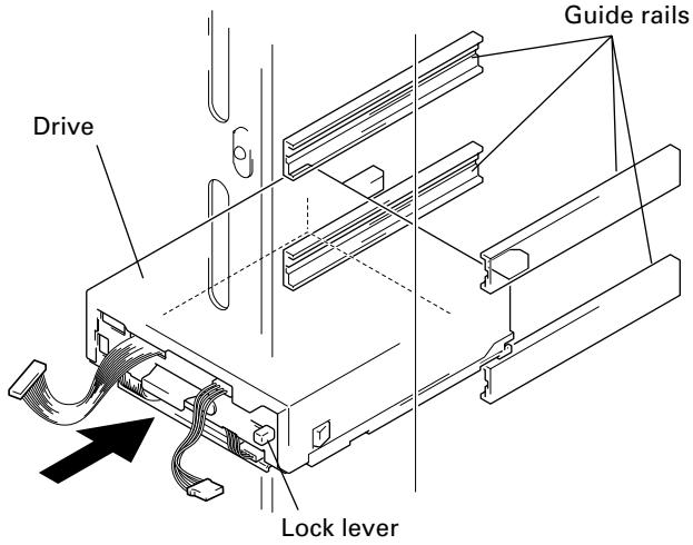
3. Installing drive units
No tools are required for attaching drive units. Note that while drives may be installed in any of the rear bays from #1 - #8, the location of the connector panel that has been attached at the time of shipment had been designed for drives to be installed in bays #1 and #2.
2. Attaching drive units
Before installation, be sure to specify the following settings at the rear of each drive to be installed. (See the operating instructions provided with drive for details.)
SCSI ID assignment
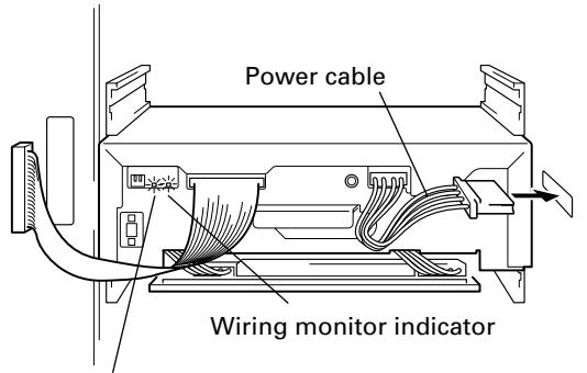
② Connect the power cable.
When the power cable has been connected, the wiring monitor indicator on the rear of the drive (orange) will light up.
When the termination switch of the drive is set to on, the termination indicator (green) will light up.
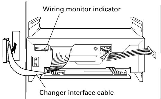
③ Connect the changer interface cable.
When the changer interface cable has been connected, the wiring monitor indicators will flash at two-second intervals.
NOTE:
Connect the changer interface cable to the connector corresponding to the bay in which the drives have been installed. (Note that labels are affixed to connectors indicating the corresponding bay number.) Note that it is extremely important to do this, as connecting the changer interface cable to a neighboring bay will result in damage to discs and the disc transport mechanism.
3. Reading and self-checking the installed drive's SCSI ID by the changer
If all drives have been assigned different SCSI IDs, a buzzer will sound once.
If the same SCSI ID has been assigned to two or more drives, a buzzer will sound three times.
NOTES:
If installed drives are to be connected to different SCSI buses, then the same SCSI ID assigned to each of the drives may be all right.
Even if none of the drives installed within a changer has been assigned the same SCSI ID, it is necessary to check that the same SCSI ID is not assigned to other devices (e.g., hard disks) on the same SCSI bus.
4. Connecting SCSI cables
After installing all drives and checking to make sure that they have been properly connected, install the SCSI interface cables.
NOTES:
Maximum usable SCSI cables length is 6 meters (including length of wiring inside changer). If the SCSI cable has extra unused connectors, connect the final (end) connector to the terminating drive; the extra intermediate connectors may be left unconnected if not required. (See page 19, "SCSI Cable Connection Example").
When installing 7 or more drives or when creating multi SCSI buses system for 6 drives or less, additional multi drive connector panels or single drive connector panels will be required.
When connecting the changer to a host computer, always be sure to first turn off the power to both the changer and the host computer. After the connections are finished, turn on the power to the changer before turning the power to the host computer back on.
The changer SCSI termination switch is set to ON at the time of shipment. Always make sure that the changer SCSI termination switch is set to OFF when the changer is not the last device in the SCSI chain.
Note that the DRM-7000/DRM-3000 is unable to recognize the existence of faulty SCSI cable connections or mistakes in the assignment of SCSI IDs, and for this reason you should always be sure to restart the host computer after installation to make sure that all drive units and the changer are properly recognized. This is the only way of confirming that all SCSI devices are installed properly.
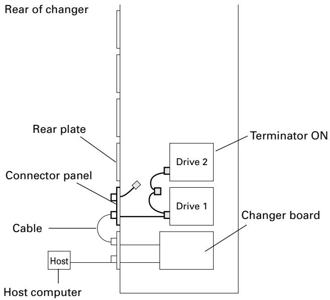
SCSI Cable Connection Example:
Install 2 internal drives within the changer in a daisy-chain configuration and connect the drives to the changer.
Total length of SCSI cables: approx. 2.1m
(Note that this does not include the length of the cable running from the host computer to the changer.)
Install 6 internal drives within the changer in a daisy-chain configuration and connect the drives to the changer.
(Additional cable for 4 drives will be needed.)
Total length of SCSI cables: approx. 2.9m
(Note that this does not include the length of the cable running from the host computer to the changer.)
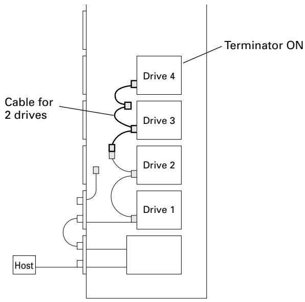
Install 4 internal drives within the changer in a daisy-chain configuration and connect the drives to the changer. (Additional cable for 2 drives will be needed.)
Total length of SCSI cables: approx. 2.5m
(Note that this does not include the length of the cable running from the host computer to the changer.)
Connect 4 drives directly to the individual host adapters. (Additional four single drive connector panels will be needed and pre-attached multi drive connector panel may be removed.)
5. Inserting disc magazines
Any of the following methods may be used to insert discs into the changer:
Insert discs into a normal-type 50-disc magazine and then insert the magazine into the changer.
Insert discs into a 20-disc hyper magazine and then insert the magazine into the changer.
Use the control panel to specify the slot into which a disc is to be inserted and transport a disc to the specified slot from the mailslot.
Issue some commands from the host computer to open the mailslot and transport a disc to the specified slot from the mailslot.
Issue some commands from the host computer to move discs in the loaded hyper magazine to some slots within the loaded 50-disc magazines.
Hyper magazine is not able to be inserted or removed when the power to the changer is turned off.
Methods 3 through 5 may be used after the changer is ready for operation. When inserting discs in these methods, always be sure to insert empty disc magazines first.
Also note that methods 3 through 5 are used when inserting locked-type 50-disc magazines. (See System administrator mode: Mailslot submode on p. 34 for further information.)
Whether or not it is possible to use methods 4 and 5 depends on the function of changer control software being used, and you should check the manual which comes with the software to check if it supports these methods to insert discs.
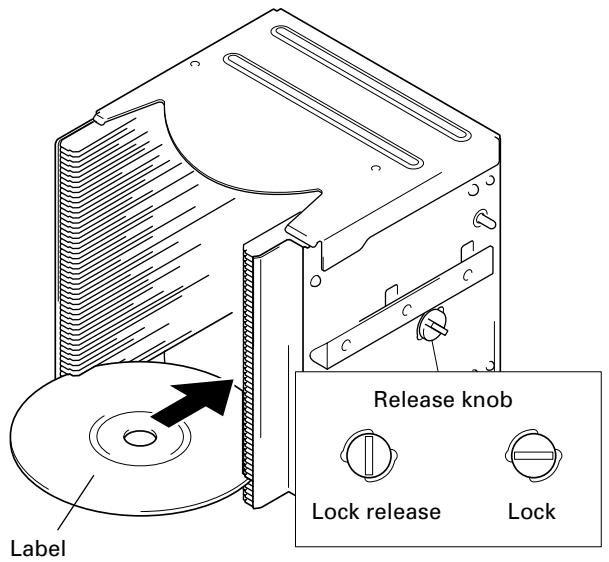
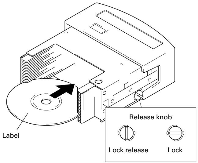
1. Insert discs into a normal-type 50-disc magazine and insert the magazine into the changer.
① Turn the release knob to the vertical direction to unlock.
NOTES:
Insert with label facing upward.
Insert discs horizontally. Otherwise it may result in damage to the discs.
Be careful not to scratch the reflective signal recording surface.
Do not turn a disc magazine upside down while the lock is disengaged. Otherwise it may result in discs falling out of the magazine.
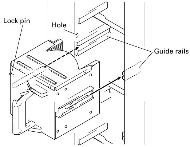
④ Insert magazine into changer.
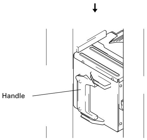
Holding the handle of the disc magazine, insert the disc magazine into the changer following the changer guide rails until it runs against the stopper.
And turn the handle to the left with pushing the magazine in so that the lock pin on the left of the magazine slides into the corresponding hole along the side of the changer.
Shown above is the insertion to the front magazine bay. Though the insertion to the rear magazine bay is almost same but note that the proper installation position is in the place where it is very secluded.
To remove a disc magazine from the changer, pull the handle towards you and pull the magazine from the changer.
Whenever a disc magazine is inserted into the changer, its ID will be automatically read in and displayed on the LCD message window within a few seconds.
M1 L o c k e d - t y p e D = *** *** ***
A similar message will also be displayed whenever a disc magazine has been removed.
M1 L o c k e d - t y p e out
If both of these messages appear together in rapid succession, it indicates that a disc magazine has not been correctly inserted, and you should check the magazine to make sure that it has been inserted properly again.
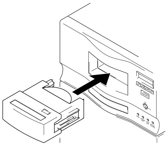
2. Insert discs into a 20-disc hyper magazine and insert the magazine into the changer.
① Turn the release knob to the vertical direction to unlock.
NOTES:
Insert with label facing upward.
Insert discs horizontally. Otherwise it may result in damage to the discs.
Be careful not to scratch the reflective signal recording surface.
Do not turn a disc magazine upside down while the lock is disengaged. Otherwise it may result in discs falling out of the magazine.
④ Insert magazine into changer.
Once the hyper magazine has been inserted partly into the changer, it will be automatically loaded in.
When the hyper magazine has been loaded, a unique magazine ID will be displayed together with the record of the locking mechanism.
Hyper-magazine is loading
↓
Uncertain-state ID ***********
Note that the magazine will be automatically ejected if the changer is unable to read the magazine ID, and that if this happens you should try inserting the magazine again.
NOTE:
If hyper magazine has been installed, see the instructions given in System administrator mode: Hyper submode (p. 35) removing the hyper magazine.
Serial numbers are assigned to each of the slots within the changer into which discs may be inserted. Note that these numbers are assigned even when no disc magazine has been inserted, and that for this reason slot numbers never change even when a new disc magazine is inserted.
DRM-7000
Disc storage location Slot number (Disc No.) Disc storage location Slot number (Disc No.) Hyper magazine Hyper Slot 20 to Slot 1 #770 to #751 hyp-20 to hyp-01 Magazine bay 15 M15 Slot 50 to Slot 1 #750 to #701 M15-50 to M15-01 Magazine bay 7 M7 Slot 50 to Slot 1 #350 to #301 M7-50 to M7-01 Magazine bay 14 M14 Slot 50 to Slot 1 #700 to #651 M14-50 to M14-01 Magazine bay 6 M6 Slot 50 to Slot 1 #300 to #251 M6-50 to M6-01 Magazine bay 13 M13 Slot 50 to Slot 1 #650 to #601 M13-50 to M13-01 Magazine bay 5 M5 Slot 50 to Slot 1 #250 to #201 M5-50 to M5-01 Magazine bay 12 M12 Slot 50 to Slot 1 #600 to #551 M12-50 to M12-01 Magazine bay 4 M4 Slot 50 to Slot 1 #200 to #151 M4-50 to M4-01 Magazine bay 11 M11 Slot 50 to Slot 1 #550 to #501 M11-50 to M11-01 Magazine bay 3 M3 Slot 50 to Slot 1 #150 to #101 M3-50 to M3-01 Magazine bay 10 M10 Slot 50 to Slot 1 #500 to #451 M10-50 to M10-01 Magazine bay 2 M2 Slot 50 to Slot 1 #100 to #051 M2-50 to M2-01 Magazine bay 9 M9 Slot 50 to Slot 1 #450 to #401 M9-50 to M9-01 Magazine bay 1 M1 Slot 50 to Slot 1 #050 to #001 M1-50 to M1-01 Magazine bay 8 M8 Slot 50 to Slot 1 #400 to #351 M8-50 to M8-01
NOTE:
Although slot numbers reach as high as '770', this does not mean that as many as 770 discs may be available within the DRM-7000.
DRM-3000
Disc storage location Slot number (Disc No.) Disc storage location Slot number (Disc No.) Hyper magazine Hyper Slot 20 to Slot 1 #370 to #351 hyp-20 to hyp-01 Magazine bay 7 M7 Slot 50 to Slot 1 #350 to #301 M7-50 to M7-01 Magazine bay 3 M3 Slot 50 to Slot 1 #150 to #101 M3-50 to M3-01 Magazine bay 6 M6 Slot 50 to Slot 1 #300 to #251 M6-50 to M6-01 Magazine bay 2 M2 Slot 50 to Slot 1 #100 to #051 M2-50 to M2-01 Magazine bay 5 M5 Slot 50 to Slot 1 #250 to #201 M5-50 to M5-01 Magazine bay 1 M1 Slot 50 to Slot 1 #050 to #001 M1-50 to M1-01 Magazine bay 4 M4 Slot 50 to Slot 1 #200 to #151 M4-50 to M4-01
NOTE:
Although slot numbers reach as high as '370', this does not mean that as many as 370 discs may be available within the DRM-3000.
6. Closing access doors
First check to make sure that all components have been installed into place and all cables have been connected.
If this has been done, close the front and the rear access doors, then the initialization of the changer mechanism will begin.
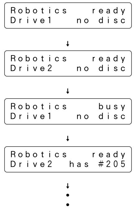
When initialization has been completed, a message like that shown below will be displayed on the LCD message window.
Robotics ready
The first line of this message is used to indicate the status of the disc changer mechanism, and the second line is used to indicate the installed drive number and to indicate whether or not a disc has been loaded into the drive in question.
Drive numbers are assigned in sequence from the lowermost to the uppermost drive.
NOTE:
If the maximum number of drives appears on the LCD message window is shorter than the number of drives installed, open the rear access door and check the power cables and the changer interface cables to all drives installed. (See System administrator mode: Door submodes on p. 37 for information on how to open the rear access door.)
The Pioneer DRM-7000/DRM-3000 has two operation modes. One is user mode performing the computer-based operations and the other is system administrator mode mainly performing manual operations from the control panel. By dividing the admitted operations into these two modes, it becomes possible to prevent interference, conflicts, or clashes occurring between operations performed from the control panel and commands issued by the host computer.
USER MODE
Once a changer has been finished its power on initialization or closing doors after installation, it will enter user mode and it will become able to be controlled by the changer control software and database management software running on the host computer. When a changer is running normally in user mode, the LCD message window will display a series of the following status messages in one-second intervals.
When operating in user mode, the changer will operate in accordance with commands issued by the host computer.
SYSTEM ADMINISTRATOR MODE
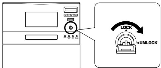
The privilege to perform operations from the control panel is given to the system administrator who keeps lock release keys. Note that the following steps must be performed in order to switch to system administrator mode.
Insert lock release key into the key switch located on the control panel and rotate 90 degrees to shift the switch to UNLOCK position.
Press the FUNCTION key.
When the changer enters system administrator mode, a message like that shown below will be displayed on the LCD message window:
System administrator mode is further divided into 8 different submodes.
These submodes enable the system administrator to read a changer's current settings or read data stored within a changer. Note that these submodes do not affect the operations performed by the host computer and the system administrator can obtain a variety of information without interfering with the control of the changer from the host computer.
Inquiry submode (see p. 26)
Config submode (see p. 26)
Option submode (see p. 28)
Info submode (see p. 32)
Maintenance submodes
These submodes are used to maintain discs and their status within the changer. Sometimes these submodes may use the disc transport mechanism. Therefore whenever the changer enter any one of these submodes, some commands issued by the host computer may be ignored.
Mailslot submode (see p. 34)
Door submodule (see p. 37)
NOTE:
The DRM-7000/DRM-3000 is designed so as to prohibit the use of maintenance submodes from the host computer. Note that while it is possible to enter system administrator mode even though the use of these submodes is prohibited, only the information submodes will be able to be used.
System administrator mode settings screen are displayed in the sequence indicated below.
Inquiry submode
Inquiry submode is the entry to system administrator mode and also the exit to user mode. Here the DRM-7000/DRM-3000 displays information its own. The data displayed is the same as that obtained when the host computer issues an SCSI INQUIRY command to the changer. Your changer's current SCSI ID and the firmware revision is seen here.
<Inquiry> ID=6 Revision \*.**
Pressing the ENT key at this time then the changer's model name and device ID (i.e., serial number) to be displayed.
DRM-7000
Pressing the ESC key causes the display to return one level above from the message currently being displayed.
To change the changer's SCSI ID, use the SCSI ID switch located at the lower left at the rear of the changer. When the setting value of the SCSI ID switch is altered, the display will show a message like that shown below. (Note that the message shown here is the message which would be displayed when the SCSI ID is changed from '6' to '5'.)
(Inquiry)ID=6(5)
Revision \*.**
The SCSI ID will be updated only when the power to the changer is turned OFF and ON or the host computer resets the SCSI bus on which the changer is.
Configsubmode
Config submode is the mode to browse the current status of the magazine bays and the rear bays. It may be used to make sure that all components currently installed in the changer have been properly recognized by the changer.
<Config> Setup browser
Pressing the ENT key causes the display to switch to the 'select bay' screen. Press the or key to select either the magazine bay or the rear bay.
Magazine-bay or Rear(drive)-bay?
Operation when the rear bay has been selected
Pressing the ENT key first displays the component loaded in rear bay #1.
The bay number to be displayed is selected by pressing the or key.
Bay#1 = Drive1
DVDROM DVD-D7563
Press ↑ or ↓ key
Bay#5 f lip unit Press or key
Bay#9 no component
Press or key
Bay#15 = M15 ID ***
Example of display for DRM-7000
If the component that has been inserted in the bay displayed is a drive unit, it is possible to read out the SCSI ID, termination switch settings, and device ID of the drive in question.
Press the ENT key when the displayed is the bay in which a drive has been inserted, then it displays the above information.
scsiID=1 TermOFF dev- ID = *
If a disc has been transported to the drive, it is also possible to press the ENT key to display the disc number.
D is c in D r i v e1
To confirm the type of magazine installed, press the ESC key to return to the bay select screen, then select the desired magazine bay.
NOTE:
Some types of stored information are in layers. Then pressing the ENT key may cause the display to proceed to the next layer and pressing the ESC key causes the display to return one level above from the message currently being displayed. Note that pressing the ESC key too many times will cause the system to return to user mode.
Operation when the magazine bay has been selected
Pressing the ENT key will cause the hyper magazine ID to be displayed.
Hyp er magazine ID ***********
If a hyper magazine is not inserted, the following message will be displayed instead.
Hyper magazine removed
Pressing the key while a hyper magazine is being displayed will cause the magazine IDs to be displayed in sequence beginning from magazine bay 1 (M1).
M1(front-bottom)ID=***
Press ↑ key ↓
M2 ID = ***********
When no disc magazine has been inserted, the message displayed will be as indicated below.
Example of display for DRM-7000
As the rear bays are multipurpose bays, sometimes some bays cannot be used as magazine bays because drives have been installed instead. Then the message displayed will be like that indicated below.
Example of display for DRM-7000
When you wish to check to see what type of disc magazine has been installed, press the ENT key.
N or m a l - t y p e
Pressing the ↑ key while magazine bay 15 (M15) is being displayed will cause the display to return to a hyper magazine display.
When you wish to view drives, press the ESC key to return to the 'select bay' screen and then select the rear bay.
NOTE:
Some types of stored information are in layers. Then pressing the ENT key may cause the display to proceed to the next layer and pressing the ESC key causes the display to return one level above from the message currently being displayed. Note that pressing the ESC key too many times will cause the system to return to user mode.
Option submode
Some changer functions may be selected at user request. In order to allow system administrators to make the most of the features provided by changer control software and database management software, optional functions may be selected as needed. Note that requirements concerning security levels or operations performed at the time of errors may also change depending on the location in which the changer has been installed, and that options should be selected accordingly.
User ’ s choice
Option submode may be used to specify the following optional functions.
1. Auto probing (Set OFF at the time of shipment)
2. Hot start (Set OFF at the time of shipment)
3. Auto eject (Set ON at the time of shipment)
4. Hyper I/E (Set ON at the time of shipment)
5. Alert buzzer (Set ON at the time of shipment)
6. Free message (Set OFF at the time of shipment)
1. Auto probing
It is possible that discs have been inserted into normal-type 50-disc magazines and hyper magazines before these magazines are inserted into the changer. But it does not mean that these imported discs are ready to use because the changer and the host computer have not recognized yet which slot holds a disc or not. Therefore the first thing to do is examining which slot a disc is in, that is called probing.
While this probing function is usually performed by the changer control software running on the host computer, in cases where users wish to perform this before connecting the changer to the host computer or in cases where the changer control software being used does not support such probing function, probe submode (see p. 36) may be used instead. Using probe submode, however, may be inconvenient since it requires that all of the disc magazines to be checked be specified one by one.
Auto probing may be used to have the changer automatically check all disc magazines which need to be checked to determine whether or not discs have been inserted.
Autoprobing?
Press the ENT key
↓
Auto probing is
set to ON/OFF
Press the key to set to ON
↓
Autoprobing is
set to ON/OFF
Press the ENT key
↓
Autoprobing
is activated
(Note that an "Auto probing is prohibited" message will be displayed if auto probing is set to OFF.)
Note that even after switching auto probing function from OFF to ON, auto probing will not actually be performed until a reset is performed, a hyper magazine is inserted or the mechanism initialization is finished after access doors are closed.
When auto probing begins, the changer will begin to check whether all slots of the disc magazines to be checked in sequence to determine whether they are "empty" or "full".
To turn auto probing temporarily off, turn the key switch to UNLOCK position and press the ESC key.
NOTES:
It takes approximately 2 minutes to check a 50-disc magazine.
- Some commands from the host computer cannot be executed while auto probing is being performed.
2. Hot start
When discs have been transported to drives and the power to the changer is turned off and then the power to the changer is turned back on, then the discs will be automatically returned to their original slots. (Note that this automatic disc return operation is not performed after a SCSI bus reset.)
For discs which are accessed frequently, however, it is possible to use the hot start feature to make those discs accessible immediately after power is turned on by leaving the discs in the drives which had used them.
Hot start function is an optional function and it enables to leave discs on the drives that had been using when the power is turning on.

(Note that a "Hot start is prohibited" message will be displayed if hot start function is set to OFF.)
NOTE:
Hot start function cannot be used when the changer control software is designed so as to force discs to be returned to their original slots.
3. Auto eject
In network environments there are often times when changers are installed near servers far from the locations in which user terminals are located.
In environments such as these, when a user uses the changer control software to issue a command requesting a disc within a changer be removed through a mailslot, it is necessary for the user to go to the location where the changer in question has been installed in order to remove the disc, but before the user reaches the changer the mailslot in which the disc has been transported may already have been opened.
This may be convenient for some cases, however, unless a system administrator resides near the changer it is as if there were no security at all, and the same holds true of the ejection of a hyper magazine.
This is the reason why it has been made possible to turn OFF auto eject function. Placing restrictions on the automatic ejection of mailslot tray and on the automatic ejection of a hyper magazine, makes it possible to maintain a certain level of security.

(Note that a "Auto eject is activated" message will be displayed if auto ejection function is set to ON.)
If auto eject function is set to OFF and a command is issued from the host computer causing a disc to be carried to a mailslot, the mailslot tray will not automatically open, and instead a message like the following will be displayed on the LCD message window.
P r e s s E N T - k e y to open mail slot
Operation
Similarly, the hyper magazine will not be automatically ejected even when an eject command is received from the host computer, and instead like the following will be displayed on the LCD message window.
P r e s s E N T - k e y to e j e c t h y p e r
To press the ENT key to cause the tray of the mailslot or the hyper magazine to be ejected, it is necessary for the key switch to be in UNLOCK position. Since the tray of the mailslot or the hyper magazine will not be ejected until a user with a lock release key goes to the place where the changer in question is installed and switches the key switch to UNLOCK position, security is ensured during the interval between the time a command is issued and the time the user actually reaches the changer.
4. Hyper I/E
While a hyper magazine is designed to be used as a disc magazine capable of accommodating 20-discs at a time, since it is also allowed to be removed without opening access doors a hyper magazine can also be used as a high-capacity mailslot.
The subsystems which make up SCSI changers may be divided into the following four types of elements:
1. Media transport element (i.e., robotics)
2. Storage elements (i.e., slots)
3. Import/export element (i.e., mailslot)
4. Data transfer elements (i.e., drives)
Although slots (which are provided by disc magazines) and mailslot are usually defined as different elements, by turning ON hyper I/E function it becomes possible to control a hyper magazine in the same way as mailslot.
Hyper I/E?
Press the ENT key
Hyper I/E is set to ON/OFF
Press the key to set to OFF
Hyper I/E is set to ON/OFF
Press the ENT key
Hyper I/E i s pro hibi t e d
(Note that a “Hyper I/E is activated” message will be displayed if hyper I/E function is set to ON.)
NOTE:
Since hyper magazines retain their attributes as storage elements even when hyper I/E function is set to ON, the changer control software may not treat a hyper magazine as an import/export element.
However, hyper I/E function should always be set to OFF when the changer control software being used does not recognize the use of multiple import/export elements or when there is a danger of erroneous operations being performed.
5. Alert buzzer
Control panel of the DRM-7000/DRM-3000 is equipped with a buzzer which is designed to sound at designated times.
- When the rear access door is opened and a drive is being inserted:
Since it is difficult to monitor progress from the LCD message window while inserting a drive from the rear access door, the buzzer sounds to provide an indication that operation is proceeding without problem.
- When the keys on the control panel are disabled:
The buzzer will sound while the FUNCTION key is being pressed.
Note that the in these cases above the buzzer will sound to provide a message to the operator in response to his/ her input, and for this reason these buzzer cannot be turned off.
- When a problem occurs with the changer:
When a problem occurs with the changer, the buzzer will continue to sound until the operator presses one of the keys on the control panel.
If in this case messages on the LCD message window or warning messages on the screen of the host computer are sufficient, this alert buzzer may be turned OFF.

(Note that a "Alert buzzer is activated" message will be displayed if the alert buzzer is set to ON.)
6. Free message
When discs are to be inserted or removed in accordance with instructions from the host computer, messages will be displayed on the LCD message window indicating the next operation which must be performed.
For example, when a disc is to be inserted or removed from a mailslot (i.e., when auto eject function has been turned OFF), the following message will be displayed.
P r e s s E N T - k e y t o o p e n m a i l s l o t
While the messages displayed on the LCD message window up until this point are the same whether a disc is being inserted or removed, since all operations after the mailslot has been opened are performed in accordance with instructions from the host computer, the changer LCD message window cannot display messages adequately.
By setting free message function ON, however, it becomes possible to have the messages displayed on the LCD message window overwritten by messages sent from the host computer, and it becomes possible to display instructions as the host computer wants to be done. It is also possible to display other information such as the name of the application controlling the changer, warning messages indicating that a disc is being written, and other information which the host computer possesses.
Freemessage?
Press the ENT key
Free message is set to ON/OFF
Press the key to set to ON
Free message is set to ON/OFF
Press the ENT key
Free message is activated
(Note that an "Free message is prohibited" message will be displayed if free message function is set to OFF.)
Note that even if free message function is activated, if no messages are received from the host computer, all messages displayed on the LCD message window will consist of messages from the changer itself.
Info submode
The DRM-7000/DRM-3000 stores data needed in order for system administrators to perform daily maintenance in nonvolatile memories, and info submode may be used to browse these data.
<Info> Databrowser
Log, Contents or Run-statistics?
Log
When you select log data browsing, it is possible to choose either error-log or import-log data.
E r r o r - I o g o r I m p o r t - I o g ?
- Error-log
The Error-log is a recorded history of operating errors detected by the changer. Errors are numbered from the most recent (1) up to a maximum of 32.
Moving the cursor to an error code and pressing the ENT key causes a description of the type of error in question to be displayed.
Press the ENT key gain to display detailed data regarding the type of error.
1:E89 2:E83
3:E99 4:E99
Press the ENT key
1:Time over on E lev at i on
Press the ENT key
E89 (05-01) 01AF 00010522
- Import-log
Import log is a sequential list of all disc slot numbers in which discs have been newly inserted into the changer when operating in mailslot submode (see p. 34).
The slot numbers displayed include the slot numbers not only for discs which have been added but also discs which have been replaced in mailslot submode. Note that discs in normal-type 50-disc magazines which have been added are displayed as a magazine unit.

Example of display for DRM-7000
Contents
Contents information of the changer may be retrieved in order to browse the status of all slots within the changer.

Example of display for DRM-7000
Note that the number displayed under the heading "Uncertain" indicates the number of slots for which the changer is still uncertain whether the slot is empty or full.
Run-statistics
The run statistics information may be retrieved to display the amount of time or the number of times operations have been performed.
Work-time sum or Number of moves?
Work-time sum
"PowerOn-time" may be selected in order to display the total amount of time the power has been turned on.
PowerOn-time or Drive work-time?
Press the ENT key
Total Power On is
* * * * * * hour * * * * min
PowerOn-time or Drive work-time?
Press the ENT key
DriVe1 works \*\*\*\*\*\*hour\*\*min
Press ↑ key ↓
Drive2 works \*\*\*\*\*\*hour\*\*min
Drive3 works \*\*\*\*\*\*hour\*\*min
Number of moves
The and keys may be pressed to display the number of any of the following four operations which have been performed.
Elevation done:
This item may be selected to indicate the number of times the elevation mechanism has been operated. Note that this information is useful as a means of determining when the elevation mechanism needs to be serviced or maintained.
Load/Unload done:
This item may be selected to indicate the number of times the loading mechanism has been operated in order to load or unload a disc into a slot or a drive. When a disc is moved from a slot to a drive, the number of load/unload operations is normally counted as two. Note that this information is useful as a means of determining when the loading mechanism needs to be serviced or maintained.
Mailslot driven:
This item may be selected to indicate the number of times a mailslot has been used. Note that an open-and-close operation is counted as one time.
Hyper driven:
This item may be selected to indicate the number of times a hyper magazine has been ejected or inserted. Note that an eject-and-insert operation is counted as one time.
E lev a t i o n d o n e \*\*\*\*\*\*\* times
Press key
Load/Unl oad done \*\*\*\*\*\*\* times
Press key
Ma i I s l o t d r i v e n \*\*\*\*\*\*\* t i m e s
Press key
Hyper driven times
Mailslot submode
Mailslot submode is designed to use mailslot with the control panel in order to exchange, eject, or add discs.
NOTE:
Although the insertion or removal of discs may normally be performed only by the host computer in order to prevent discrepancies from arising in the database, it is permitted for the system administrator to use this mode to insert or remove discs. When doing so, however, the system administrator must make a record of the slots to which discs have been moved and, when necessary, also perform database maintenance. (Note that the slot numbers of slots for which discs have been added may be read by using the import-log in Info submode.)
Import & Export
If you press the ENT key at this point, the following "Swap, Remove, or Add some discs?" selection menu will appear. Move the cursor to the menu item to be selected and press the ENT key to make your selection.
Swap,Remove or Add some discs?
Swap
SlotNo.? #*** M**-**
- Use the or keys to specify the slot number of the slot for which you wish to exchange discs and press the ENT key.
(Note that each time either one of the or keys is pressed, the slot numbers in which discs have been inserted and the slot numbers for which the changer is still uncertain whether the slot is empty or full will be shown in sequence.)
Removing #\*\*\* as the old disc
If there is a disc in the specified slot, the disc will be carried to the mailslot, the tray will open, and the following message will be displayed.
Replacediscs &pressENT-key
If there is no disc in the specified slot, the tray will open and the following message will be displayed.
P l a c e a new disc & p r e s s E N T-k e y
- Place the new disc in the tray and press the ENT key. The tray will close, the following message will be displayed, and the disc will be carried to the specified slot.
The new disc is moving to \# ***
When the disc swapping operation has been completed, the message displayed on the LCD message window will return to the initial swap disc message with the next slot number corresponding to the condition described above being displayed.
To exit swap mode, press the ESC key.
Remove
D is c No. ? #*** M**-**
- Use the or keys to specify the slot number of the disc you wish to remove and press the ENT key. (Note that discs may be removed by this mode only from slots for which it is confirmed that a disc has been inserted, and that the selection menu displayed will not change when the ENT key is pressed if there is no confirmed slot in which a disc has been inserted.)
The specified disc will be carried to the mailslot, the tray will open, and the following message will be displayed.
Remove the disc & press ENT-key
- Remove the disc and press the ENT key to close the tray.
When the disc has been removed, the message displayed on the LCD message window will return to the initial remove disc message with the next slot number corresponding to the condition described above being displayed.
To exit remove mode, press the ESC key.
Add
Slo tNo.? #*** M**-**
- Use the or keys to specify the slot number to which you wish to add a disc and press the ENT key. (Note that discs may be added by this mode only to slots for which it is confirmed that no disc has been inserted, and that the selection menu displayed will not change when the ENT key is pressed if there is no slot confirmed empty.)
The mailslot tray will open and the following message will be displayed.
P l a c e a new disc & p r e s s E N T-k e y
- Place the new disc in the tray and press the ENT key. The tray will close, the following message will be displayed, and the disc will be carried to the specified slot.
The new disc is moving to \#
When the disc has been added, the message displayed on the LCD message window will return to the initial add disc message with the next slot number corresponding to the condition described above being displayed. To exit add mode, press the ESC key.
NOTE:
If you cannot add a new disc in add mode, add the disc in swap mode instead.
Hyper submode
Hyper submode is designed to eject a hyper magazine. Since the DRM-7000/DRM-3000 is not equipped with an exclusive key to eject a hyper magazine, you must enter this mode to make the ENT key into the eject key.
Eject & Inject
- When the ENT key is pressed, the changer will check to see if any hyper magazine discs are currently used in drives. If there are such discs currently in drives, the following message will be displayed.
Host must return all hyper's disc
It is the host computer possessing the authority to return discs in drives to disc magazines. Therefore, if you wish to eject the hyper magazine right now, you must return to user mode first and issue a command requesting the discs be returned from the host computer.
When all the discs have been returned to the hyper magazine, the following message will be displayed.
Press ENT-key to eject
- Pressing the ENT key will cause the following messages to be displayed and the hyper magazine to be ejected.
Hyper-magazine is unloading
Hyp er-magazine is eje cted
If you wish to exit this mode without replacing the hyper magazine, press the ESC key three times to return to user mode.
If you wish to replace hyper magazines, insert the new hyper magazine. Note that the hyper magazine will be automatically loaded once it has been partway inserted, and that you should be careful not to add excessive force when inserting a magazine.
Hyper-magazine is loading
When the hyper magazine has been loaded, a unique magazine ID will be displayed together with the record of the locking mechanism.
When there are no records of the lock ever having been unlocked, the message displayed will be as follows.
L o c k e d - s t a t e
ID=***
When there are records of the lock having been unlocked, the message displayed will be as follows.
Uncertain-state ID \*\*\*\*\*\*\*\*\*\*\*
Note that the magazine will be automatically ejected if the changer is unable to read the magazine ID, and that if this happens you should try inserting the magazine again.
Probe submode
It is possible that discs have been inserted into normal-type 50-disc magazines and hyper magazines before these magazines are inserted into the changer. But it does not mean that these imported discs are ready to use because the changer and the host computer have not recognized yet which slot holds a disc or not.
Probe submode is used to examine which slot a disc is in. While this probing function is usually performed by the changer control software running on the host computer, in cases where users wish to perform this before connecting the changer to the host computer or in cases where the changer control software being used does not support such probing function, probe submode may be used instead.
Slot initialize
- If you press the ENT key at this point, the magazine bay numbers into which magazines have been loaded will be displayed in sequence.
I n i t i a l i z e s l o t s of M1?
- Press the or key to select a disc magazine and press the ENT key to confirm your selection. The changer will examine each of the slots within the disc magazine in sequence to check whether or not a disc has been inserted.

When all fifty slots have been probed, a message will be displayed asking if you wish to continue.
Select "Yes" to continue and "No" to quit and then press the ENT key.
Probe submode may also be used to examine which slot of the hyper magazine a disc is in, in the same manner as for 50-disc magazines.
Note that once probe submode has been used to perform a check on a given disc magazine, there is no need to ever check again for the presence or absence of discs in that magazine as long as that magazine is not removed from the changer.
Door submode
This mode is used to open the access doors to swap 50-disc magazines, to swap or add drives.
Note that it is necessary to make sure that all discs within the changer have been returned to their disc magazines or mailslot. Otherwise neither of the access doors can be opened.
This may be done by the system administrator, who should first check the status of the drives from the host computer before halting service and returning all discs.
Open & Rebuild
- When the ENT key is pressed, the changer will check to see if any discs are currently used in drives. If there are any discs in drives, the following message will be displayed.
Host must return
every disc first
If this message is displayed, press the ESC key to return to user mode and issue a command requesting the discs be returned from the host computer.
When it has been confirmed that there are no discs in drives, the following message will be displayed. Move the cursor to specify the access door(s) to be opened.
Frent, Rear
Or Both?
- Pressing the ENT key will cause the specified access door(s) to be opened.
Frent-door:Open
Rear-door : Close
NOTE:
When either of the access doors is opened, the system will automatically return to user mode. To enter a different submode, press the FUNCTION key to re-enter system administrator mode (see p. 24).
ADDING DRIVE UNITS
Any drive designed for use in the DRM-7000/DRM-3000 changer can easily be added as a new drive.
The power unit provided as standard equipment is designed to provide sufficient electrical capacity to support up to 8 drives mounted in rear bays #1 to #8. When adding additional drives to the rear bays #9 – #16 of the model DRM-7000, however, an optional additional power unit is required.
Warning about static electricity
Always be sure never to touch the contacts or ports of any connectors when installing additional drives or any other type of add-on equipment. Also be sure to touch a metallic surface on the changer before beginning the adding operations.
NOTES:
- When disconnecting drive cables that had been connected before to make the work easier, always be sure to disconnect those cables in the following order (i.e., the opposite order from that in which they are connected):
1. SCSI interface cable
2. Changer interface cable
3. Power cable
- If you wish to add a drive to a SCSI bus where the termination for an existing drive has been turned on, the termination for the new drive to be added must be turned on and the termination for the existing drive turned off.
How to add a drive
1. Enter system administrator mode and enter door submode to open the rear access door.
The following message will be displayed on the LCD message window.
F r o n t - d o o r : C l o s e
Rear-door : Open
2. Attach add-on connector panels, if necessary
Screwdriver

3. Place the drive on the changer guide rails, push the drive in until the lock lever on the drive shifts to the locked position. Maybe you can hear a clicking sound then.

4. Connect the power cable.
If it is difficult to work, the SCSI interface cables of other drives should be disconnected before continuing.
- When the power cable has been connected, the wiring monitor indicator on the rear of the drive (orange) will light up.
- When the termination switch of the drive is set to on, the termination indicator (green) will light up.

Termination indicator
5. Connect the changer interface cable.
- When the changer interface cable has been connected, the wiring monitor indicator will flash at two-second intervals.

NOTE:
Connect the changer interface cable to the connector corresponding to the bay in which the drives have been installed. (Note that labels are affixed to connectors indicating the corresponding bay number.) Note that it is extremely important to do this, as connecting the changer interface cable to a neighboring bay will result in damage to discs and the disc transport mechanism.
6. The changer will then read the drive's SCSI ID and compare the drive's settings to those of existing drives.
- If all drives have been assigned different SCSI IDs, a buzzer will sound once.
- If the same SCSI ID has been assigned to two or more drives, a buzzer will sound three times.
NOTES:
- If installed drives are to be connected to different SCSI buses, then the same SCSI ID assigned to each of the drives may be all right.
- Even if none of the drives installed within a changer has been assigned the same SCSI ID, it is necessary to check that the same SCSI ID is not assigned to other devices (e.g., hard disks) on the same SCSI bus.
7. Connect the SCSI interface cable.
If you have disconnected the SCSI interface cables of any other drives in Step 4, be sure to remember to reconnect those cables.
8. Enter system administrator mode and enter config submode (see p. 26) to check that the changer recognizes all the internal drives.
For example, three DVD-ROM drives and one DVD-R drive have been added in the rear bays beginning from Bay #1 in sequence, the following messages will be displayed.
$$
\text {B a y \# 1} = \text {D r i v e 1}
$$
$$
D V D R O M \quad D V D - D 7 5 6 3
$$
$$
\text {P r e s s} \uparrow \text {k e y}
$$
$$
\downarrow
$$
$$
B a y \# 2 = D r i v e 2
$$
$$
D V D R O M \quad D V D - D 7 5 6 3
$$
$$
\text {P r e s s} \uparrow \text {k e y}
$$
$$
\downarrow
$$
$$
B a y \# 3 = D r i v e 3
$$
$$
D V D R O M \quad D V D - D 7 5 6 3
$$
$$
\text {P r e s s} \uparrow \text {k e y}
$$
$$
\downarrow
$$
$$
B a y \# 4 = D r i v e 4
$$
$$
D V D - R \quad D V D - R 7 3 2 2
$$
$$
\text {P r e s s} \uparrow \text {k e y}
$$
$$
\downarrow
$$
$$
B a y \# 5
$$
$$
\texttt {n o c o m p o n e n t}
$$
NOTES:
- If the changer interface cable has not been properly connected, the changer will not be able to recognize the drive at all. You should check the wiring monitor indicator located on the back of the drive. When the cables have been properly connected, the indicator ought to be flashing.
If the indicator is lit, check to make sure that the changer interface cable of the drive in question has been properly connected.
If the indicator is not lit, check to make sure that the power cable of the drive in question has been properly connected. If the cables need to be reconnected, reconnect the power cable before reconnecting the changer interface cable.
- If the drive is recognized but the model name of the drive is not displayed in the lower half of the LCD message window, disconnect all three cables and reconnect them again.
Order in which cables are to be disconnected:
1. SCSI interface cable
2. Changer interface cable
3. Power cable
Order in which cables are to be reconnected:
1. Power cable
2. Changer interface cable
3. SCSI interface cable
9. To view the settings for all drives which have been recognized, press the ENT key to proceed to the next layer in the message display.
- The SCSI ID, termination switch setting, and unique device ID of each drive will be read in and displayed at the same time on the same message window.
- If four drives have been connected in a daisy chain configuration and termination has been turned on for the fourth drive in the chain, the messages displayed will be as indicated below.

Press the ENT key

Press the ESC key to return to the previous message


Press the ENT key

Press the ESC key to return to the previous message and then press the key

Press the ENT key

Press the ESC key to return to the previous message and then press the key


Press the ENT key
NOTES:
- If the SCSI IDs or termination switch settings displayed differ from those which set on the backs of drives, or if a drive's device ID fails to be displayed, it is likely that the corresponding cables were improperly connected. If this happens, follow the steps outlined below to properly reconnect all the cables.
Order in which cables are to be disconnected:
1. SCSI interface cable
2. Changer interface cable
3. Power cable
Order in which cables are to be reconnected:
1. Power cable
2. Changer interface cable
3. SCSI interface cable
- If the device ID of a drive cannot be read, then it will be impossible for the host computer to perform automatic configuration.
10. Press the ESC key several times to return to user mode and close the rear access door.

Press the ESC key

As the remaining steps which must be performed may differ depending on the changer control software being used, please consult the manual for the changer control software being used for further instructions.
Also note that it may be necessary to restart the host computer before it can recognize the drives which have been added.
EXCHANGING DRIVE UNITS
Drives may be exchanged following the same procedure as that describing above for adding new drives.
Described below is the procedure to be following when exchanging drives, and it also eliminates the worry of making mistakes in the drive bay number which is to be exchanging.
NOTE:
Unless there is some special reason, the SCSI ID and termination switch settings of the drive to be installed to replace should be the same as those of the drive to be replaced.
How to exchange a drive
1. Enter system administrator mode and enter door submode to open the rear access door.
The following message will be displayed on the LCD message window.
$$
\begin{array}{l} \text {F r o n t - d o o r : C l o s e} \\ \text {R e a r - d o o r : O p e n} \end{array}
$$
2. Enter system administrator mode again and enter config submode to select the rear bay.
$$
\begin{array}{c} \boxed { \langle C o n f i g \rangle} \\ \text {S e t u p b r o w s e r} \\ \text {P r e s s t h e E N T k e y} \\ \downarrow \end{array}
$$
$$
\begin{array}{l} \text {M a g a z i n e - b a y o r} \\ \text {R e a r (d r i v e) - b a y ?} \end{array}
$$
$$
\begin{array}{c} \text {S e l e c t " R e a r " a n d p r e s s t h e E N T k e y} \\ \downarrow \end{array}
$$
$$
\begin{array}{l} \text {B a y # 1} = \text {D r i v e 1} \\ \text {D V D R O M D V D - D 7 5 6 3} \end{array}
$$
3. Use the or key to select the bay in which the drive to be replaced is currently inserted.
Note that the messages actually displayed may lack some of the following information if the drive being replaced has been out of order.
$$
\begin{array}{l} \text {B a y # 3} = \text {D r i v e 3} \\ \text {D V D R O M D V D - D 7 5 6 3} \end{array}
$$
4. Make sure the wiring monitor indicator (orange). It is located on the back of the drive and ought to be flashing at half-second intervals if the drive has been selected in Step 3. Then disconnect the cables to the drive.
Order in which cables are to be disconnected:
1. SCSI interface cable
2. Changer interface cable
3. Power cable
5. Remove the drive.
If it is difficult to work, the SCSI interface cables of other drives should be disconnected before continuing.
6. Check the SCSI ID and termination switch settings of the drive which has just been removed, and set the SCSI ID and termination switch settings of the drive which is to be inserted in its place to the same settings.
7. Insert the new drive and connect the power cable.
- When the power cable has been connected, the wiring monitor indicator on the rear of the drive (orange) will light up.
- When the termination switch of the drive is set to on, the termination indicator (green) will light up.

8. Connect the changer interface cable.
- When the changer interface cable has been connected, the wiring monitor indicator will begin flashing at half-second intervals.

9. Compare the SCSI ID and termination settings of the newly installed drive against those of the removed drive.
- If the SCSI ID of the new drive is the same as that of the drive which has just been removed, the buzzer will sound once.
- If the SCSI ID of the new drive is not the same as that of the drive which has just been removed, the buzzer will sound three times.
10. Connect the SCSI interface cable.
If you have disconnected the SCSI interface cables of any other drives in Step 5, be sure to remember to reconnect those cables.
11. Check the drive device ID displayed on the LCD message window.
$$
\text {B a y} 3 = \text {D r i v e} 3
$$
$$
D V D R O M \quad D V D - D 7 5 6 3
$$
Press the ENT key
↓
$$
\text {s c s i D} = 3 \quad \text {T e r m O F F}
$$
$$
d e v - I D = * * * * * * * *
$$
NOTES:
- If the SCSI ID and termination switch settings displayed differ from those which set on the back of the drive, or if a drive's device ID fails to be displayed, it is likely that the corresponding cables were improperly connected. If this happens, follow the steps outlined below to properly reconnect all the cables.
Order in which cables are to be disconnected:
1. SCSI interface cable
2. Changer interface cable
3. Power cable
Order in which cables are to be reconnected:
1. Power cable
2. Changer interface cable
3. SCSI interface cable
- If the device ID of a drive cannot be read, then it will be impossible for the host computer to perform automatic configuration.
12. Press the ESC key several times to return to user mode and close the rear access door.

As the remaining steps which must be performed may differ depending on the changer control software being used, please consult the manual for the changer control software being used for further instructions.
NOTE:
If you will replace drives without using the procedure described above, you must be more careful not to remove the wrong drive. In such a case, the installation procedure of the drive is the same as that described in "How to add a drive" (on p. 38), and note that the conditions under which the buzzer is sounded differ slightly.
TROUBLESHOOTING
Here are some tips for solving common problems that may be encountered. Some defects with discs or lack of experience in performing operations may result in errors being displayed or in problems which seem breakdowns. Simple mistakes or misconceptions can be corrected or cleared away by using the following table which has been provided for troubleshooting of the system administrator.
If you still find it impossible to correct a problem or if an error message refuses to go away even after consulting the list below and taking the recommended action, contact your service representative or the dealer from which you purchased the product for assistance.
Also consult the section "TO AVOID PROBLEMS" on p.12.
Description of problem Message display Possible cause Recommended action Buzzer sounds when access door is open and you insert a magazine. M**Disc Not Correct One or more discs has not been properly placed in the slots of that magazine. Remove the magazine and check to see if any discs are protruding. Buzzer sounds when you insert a hyper magazine. Hyper magazineDisc Not Correct One or more discs has not been properly placed in the slots of that hyper magazine. Remove the hyper magazine and check to see if any discs are protruding. Buzzer sounds when power is first turned on and initialization begins. E83Disc Not Correct ● Some foreign object has been detected within the changer.● Some discs are protruding from their magazines. Open the access door and check to see if there is anything seems to be blocking the optical sensor. If you find it then remove it. Buzzer may stop. Buzzer sounds and system refuses to enter system administrator mode when you press the FUNCTION key. The key switch is set to the locked position. Use the lock release key to turn the key switch to UNLOCK position. Unable to enter Mailslot or Door submode even though it is possible to enter Inquiry or Config submode. ● The robotics were busy at the time you pressed a key.● Swithover to these maintenance submodes has been prohibited from the host computer. ● Try again after making sure the ROBOTICS BUSY indicator is off.● Check to see if those operations has been prohibited from the host computer. In Mailslot submode; Swap or Add, tray opens again soon after it was closed. Place a new disc & Press ENT-key Mailslot was closed without placing a disc on the tray. Press the ESC key to halt the swap disc or add disc operation. In Mailslot submode; Remove, tray opens again soon after it was closed. Remove the disc & Press ENT-key Mailslot was closed without removing the disc from the tray. Remove the disc from the tray. As the discs in drives are not returned even after the power is turned off and back on, it is impossible to open access doors in Door submode. The hot start function has been turned on. Turn hot start function off and turn the power off and then back on. When the discs have been returned, re-enter Door submode and open the access door. Access door refuses to open after trying to open it in Door submode. The access door is blocked and is unable to open. Remove whatever is blocking the access door and try to open the access door again. Access door selection screen fails to appear when trying to open access door in Door submode. Host must return every disc first There are some discs remaining in drives. Return to user mode, issue REZERO command from the host computer requesting that all discs be returned, and try to perform the operation again after all discs have been returned. Hyper magazine cannot be ejected in Hyper submode. Host must return all hyper's disc There are some discs that from the hyper magazine remaining in drives. Return to user mode, issue REZERO command from the host computer requesting that all discs be returned, and try to perform the operation again after all discs have been returned. There exists a drive or drives which fail to be recognized by the host computer even though they have been recognized in Config submode. ● SCSI cable has not been connected properly.
● SCSI ID or termination settings have not been correctly specified.
● The total length of the SCSI cables is too long.
● Operator has forgotten to reboot the host computer. ● Make sure that the SCSI cables have been connected properly.
● Check to see if there is any device on the same bus with the same SCSI ID and to see that the SCSI chain has been properly terminated.
● Re-configure the SCSI chain so that the total length of all the cables does not exceed the maximum allowable length.
● Reboot the host computer. There exists a drive which fails to be recognized by the host computer, and the SCSI ID of the drive is set to '7' when checked in Config submode. scsiID=7 TermOFF dev-ID= ● The power cable for the drive in question has not been connected.
● Drives have been inserted in rear bays #9 through #16 without additional power supply unit. ● Open the rear access door and check to see if the power cable has been properly connected.
● The power supplied by the power supply included as standard equipment is sufficient only for operating drives in bays #1 through #8. Reinstall the drive in one of these bays or install the additional power supply unit. Unable to properly read a disc which has been inserted in a drive. ● The disc has been inserted upside down.
● The disc is soiled or scratched. ● Check to see if the disc has been inserted upside down.
● Check to see if the disc is soiled or scratched, and wipe away any soil or replace the disc. An error code is displayed on the LCD message window and the backlight flashes and the buzzer is sounded. E88, E89,E99, etc. A mechanical error has occurred which has made the changer unable to continue in operation. In system administrator mode, open the access door and take whatever action is required in order to eliminate the error condition. The LCD message window does not come on when the power is turned on. Pressing the operation keys has no effect. The changer SCSI termination switch is set to OFF or the SCSI cable is not properly connected. ● When installing is not finished, turn the SCSI termination switch to ON and turn the power OFF and ON.
● If the SCSI cable is not properly connected, turn off the power. And after connection the cable properly, turn on the power again. Buzzer sounds when magazine is loaded. ● Memory Failure
● Error Magazine's memory data is not being read correctly. ● Remove and reinsert magazine.
● If the magazine data still can't be read properly, perform a "PROBE" of the magazine, ten open and close the door.
SPECIFICATIONS
DRM-7000 DRM-3000 General specifications Description 700-disc changer 300-disc changer Power supply AC 100 V – 240 V, 50/60 Hz ← Power consumption Maximum of 5.5 A (500 W) Maximum of 3.3 A (300 W) Weight of main unit (including placement fixtures) 91.7 kg (202 lb 3 oz) 60.6 kg (133 lb 10 oz) External dimensions (including placement fixtures) 760 x 795 x 1520 mm (W x D x H) 760 x 729 x 872 mm (W x D x H) 29-15/16 x 31-5/16 x 59-7/8 in (W x D x H) 29-15/16 x 28-11/16 x 34-5/16 in (W x D x H) Operating requirements* +5 °C to +35 °C (+41°F to +95°F) ← Humidity* 5% to 85% (with no condensation) ← Storage requirements -40 °C to +60 °C (-40°F to +140°F) ←
* The figures for permissible operating temperature and humidity may change depending on the components loaded. For details, consult the operating instructions for each component used.
Functional specifications
Maximum number of discs 720 (12-cm discs) 320 (12-cm discs) Maximum number of disc magazines 50-disc magazines 14 6 20-disc hyper magazine 1 ← Maximum number of components 16 8 Items included 20-disc hyper magazine 1 ← Changer/drive SCSI cable 1 ← Power cord (for use in Canada and USA) 1 ← Power cord (for use in Japan) 1 ← Base stabilizer 4 2 Screw for use in attaching Base stabilizer 12 6 Lock release key 2 ← Operations Instructions 1 ←
- The external design of this product or any of the above specifications may be changed at any time without prior notification.
SCSI connector specifications

1) Pin layout of SCSI connectors
Signal name Pin No. Signal name GROUND 1 26 -DB(0) GROUND 2 27 -DB(1) GROUND 3 28 -DB(2) GROUND 4 29 -DB(3) GROUND 5 30 -DB(4) GROUND 6 31 -DB(5) GROUND 7 32 -DB(6) GROUND 8 33 -DB(7) GROUND 9 34 -DB(P) GROUND 10 35 GROUND GROUND 11 36 GROUND NC 12 37 NC NC 13 38 TERMPWR NC 14 39 NC GROUND 15 40 GROUND GROUND 16 41 -ATN GROUND 17 42 GROUND GROUND 18 43 -BSY GROUND 19 44 -ACK GROUND 20 45 -RST GROUND 21 46 -MSG GROUND 22 47 -SEL GROUND 23 48 -C/D GROUND 24 49 -REQ GROUND 25 50 -I/O
NOTES:
Pin No. 12 to 14, 37 and 39 are not grounded.
- The connectors are of the shielded type.
- For details on the control commands, refer to the separate specifications manual.
2) Electrical specifications of SCSI
Output characteristics The signals driven by SCSI equipment present the following output characteristics. True (LOW): VOL = 0.0 to 0.4 V DC IOL = 48 mA (0.5 V DC) max. False (HIGH): VOH = 2.5 to 5.25 V DC Input characteristics The signals driven by SCSI equipment present the following input characteristics. True (LOW): VOL = 0.0 to 0.4 V DC IOL = -0.4 mA (0.4 V DC) max. False (HIGH): VOH = 2.0 to 5.25 V DC
NOTES:
- As the SCSI interface is of the single-ended type, it should be terminated on both ends of the cable.
- The maximum recommended length of an SCSI cable is 6 meters (20 feet) (including internal wiring).
Maintenance
In order to ensure safe and proper functioning of this unit, we recommend regular maintenance. Extended service life can be expected if maintained properly.
IMPORTANT

Ce symbole de l'éclair, place dans un triangle équilatéral, a pour but d'attirer l'attention de l'utiliser sur la présence, à l'intérieur du coffret de l'appareil, de "tensions dangereuses" non isolées d'une grande suffisante pour représentier un risque d'électrocution pour les étres humains.
ATTENTION
DANGER D' ELECTROCUTION NES PAS OUVIR
ATTENTION:
POUR EVITER TOUT RISQUE D' ELECTROCUTION, NE PAS ENLEVER LE COUVERCLE (NI LE PANNEAU ARRIERÉ). AUCUNE PIECE REPARABLE PAR L' UTILISATEUR NÉSETROUVEAL'INTERIEUR, CONFIER TOUT ENTRETIEN A UN PERSONNEL QUALIFIE UNIQUEMENT.

Ce point d'exclamation, place dans un triangle equilateral, a pour but d'attirer l'attention de l'utiliser sur la presence, dans les documents qui accompagnent l'appareil, d'explications importantes du point de vue de l'exploitation ou de l'entretien. H002AFr
[POUR LES MODELES A DESTINATION DE L'EUROPE ET DU ROYAUME-UNI]
ATTENTION
Ce produit renferme une diode à laser d'une catégorie supéroeire à 1. Pour garantir une sécurité constante, ne pas-retirer les couvercles ni essayer d'acceder à l'intérieur de l'appareil.
Pour toute réparation, s'adresser à un personnel qualifié.
La note suivante se trouver sur le panneau arrière de votre lecteur.
CLASS 1 LASER PRODUCT
LASER KLASSE 1
APPAREIL À LASER DE
CLASSE 1
ATTENTION: CET APPAREIL N'EST PAS IMPERMEABLE, AFIN DE PREVENIR TOUT RISQUE DE CHOC ELECTRIQUE OU DE DEBUT D'ENCENDIE, NE PAS EXPOSER CET APPAREIL A L'HUMIDITE OU A LA PLUIE ET NE PLACER AUPRES DE LUI AUCUNE SOURCE D'EAU, TELS QUE VASES, POTS DE FLEUR, COSMETIQUES, FLACONS DE MEDICAMENTS, ETC. H001Af
ATTENTION: CE PRODUIT ETANT MUNI D'UN TYPE DE FICHE A TROIS FILS DE TERRE, C'EST A DIRE UNE FICHE AYANT UNE TROSIÈME BROCHE DE TERRE, IL S'ADAPTERA UNIQUÉMENT DANS UNE PRISE DE TERRE. CECI EST UNE MESURE DE SECURITE. SIVOUS N'ARRIVEZ PAS AINSERER LA FICHE DANS LA PRISE DE COURANT CONTACTEZ VOITRE ELECTRICIEN AFIN QU'IL CHANGE LA PRISE DE COURANT OBSOLETE. NE PAS MODIFIER LA FONCTION DE SECURITE OFFERTE PAR LA FICHE DE TERRE. H043 Fr
Conditions de Fonctionnement
H045 Fr
Tempéraure et humidité ambiente lors du fonctionnement: +5 °C - +35 °C (+41 °F - +95 °F); inférieur à 85 % RH (events d'aération non obstrués)
Ne pas installer dans les lieux suivants
- Lieux exposés à la lumière direct du soleil ou lumière artificielle forté
- Lieux exposés à une forte humidité ou lieux peu ventilés
Pour les apparèils enchouchables, la prise doit être installée à proximitément et aisément accessible.
La production de bruits acoustiques est inférieure à 70 dB. (ISO7779/DIN45635)
Nous vous remercions pour cet achat d'un produit Pioneer. Nous vous demandons de dire soigneusement ce mode d'emploi; vous serez ainsi à même de faire correctement fonctionner l'appareil. ÀpRES avoir bien lu le mode d'emploi, le ranger dans un endroit sur pour pouvoir s'y référer ultérieurement.
Dans certains pays ou certaines régions, la forme de la fiche d'alimentation et de la prise d'alimentation peut différer de cette qui figure sur les schémas, mais les branchements et le fonctionnement de l'appareil restent les mêmes.
TABLE DES MATIERES
CHARACTERISTIQUES 49
INSTRUCTIONS DE SECURITE 50
A LIRE AVANT USAGE 51
Instructions de sécurité 51
Gestion de medias hors ligne 51
Choix de la configuration du système 52
Periphériques 52
Accessoires fournis 54
Disques 55
POUR ÉVITER DES PROBLEMES 56
NOMS ET FONCTIONS
DES ELEMENTS 58
INSTALLATION 60
FONCTIONNEMENT 68
Modeutilisateur 68
Mode administrateur de système 68
Ajout de lecteurs 82
Echange de lecteurs 85
AUTRES SUJETS 88
Dépannage 88
Caracteristiques techniques 90
CONCEPTION FLEXIBLE
Le changeur de disque Pioneer DRM-7000/DRM-3000 a ete concu de façon a ce qu'on puisse acheter et installer plusieurs composants en meme temps afin de repondre a des besoin variés.
Le DRM-7000/DRM-3000 de Pioneer est équipé de baies (c.- à-d. des espaces pouvant accueillir des lecteurs ou des magasins à 50-disques) situées à l'avant et à l'arrière de l'appareil. Ces baies sont équipées de portes d'accès qui peuvent être largement ouvertes afin de facilititer l'installation ou le retrait des composants.
La baie avant est limitée à un usage exclusif avec des magasins de 50 disques, tandis que la baie arrêté est conscience comme une zone à usages multiples.
Capacité de chargement
DRM-7000 DRM-3000 Baie avant
Magasins à 50 disques seulement 7 3 Baie arrêté
Composant Max. 16 Max. 8 Magasins à 50 disques Max. 7 Max. 3
Le nombre maximum de périhériques en option pouvant être installés dépend de ceux qui sont utilisés. Pour plus de détails, reportez-vous au mode d'emploi de vos périhériques en option.
Exemple de combinaison
DRM-7000 DRM-3000 Accent sur capacité de donnéesées 2 lecteurs 2 lecteurs 720 disques 320 disques Accent sur performances 16 lecteurs 8 lecteurs 370 disques 170 disques
Au besoin, vous pouvez commencer en laissant vides les espaces de vos baies et en y ajoutant des éléments à mesure de vos exigences.
TROIS TYPES DIFFERENTS DE MAGASINS À DISQUE, EQUIPES D'UNE MEMOIRE INTERNE
Pioneer fournit trois types différents de magasins à disque, faciles à utiliser dans différentes applications.
La caractéristique principale de l'hypermagasin est sa mobilité. Il peut être introduit et enlevé sans qu'il soit nécessaire d'ouvrir la porte d'accès. Il est aussi équipé d'un système de mémoire intelligente qui enregistre toutes les opérations effectuees par l'utilisateur dans son mecanisme de verrouillage/déverrouillage. Chaque DRM-7000/DRM-3000 de Pioneer est livré en série avec un hypermagasin.
Magasin de 50 disques (type verrouillable):
Ce modele est idéal pour gérer des medias hors ligne, ou la sécurité et l'invariabilité sont importantes. Le mecanisme de verrouillage empêche tout retrait de disque du magasin à l'extérieur du changeur.
Magasin de 50 disques (type normal):
Ce modèle est pratique pour importer un grand nombre de disques dans le changeur ou de les en exporter. Un mécanisme de verrouillage intégré empêche tout retrait de disques du magasin lorsque celui-ci se trouve à l'extérieur du changeur.
FACILITE D'INSTALLATION
Pour permettre le raccordement du changeur à un système de gestion de données existant ou l'elaboration d'un nouveau système de gestion de données, l'ordinateur hote doit etre capable d'identifier correctement le changeur et tous les lecteurs qu'il contient, tous les cables doivent etre raccordes et les parametes doivent etre spécifiés pour que l'ordinateur hote puisse contrcler le changeur et les lecteurs.
Le Pioneer DRM-7000/DRM-3000 est concu non seulement pour faciliter l'installation et l'ajout de nouveaux lecteurs, mais il dispose aussi d'un grand nombre de fonctions permettant de configurer plus facilement l'ordinateur hôte.
FONCTIONS DE SECURITE VISANT A EVITER DES OPERATIONS ERRONEES OU NON AUTORISEES
Afin d'eviter les interférences, conflicts ou incompatibilités entre les opérations manuelles et les opérations effectuees à l'aide de I'ordinateur, une procedure a ete createe pour entrer en mode Administrateur de système. Chaque personne qui souhaite efectuer des opérations à I'aide du tableau de commande doit d'abord entrer en mode Administrateur de système en utilisant la clé de déverrouillage fournie. Il est également possible d'interdre I'accès a certains sous-modes en envoyant une commande à I'aide de I'ordinateur hote. On peut aussi accorder des privilèges de sécurité aux administrateurs de système en possession d'une clé de déverrouillage. Dans ce cas, seul I'administrateur de système a I'autorisation d'effectuer des opérations de manipulation directe de disques, comme I'ouverture d'échangeurs et I'éjection d'hypermasins.
TABLEAU DE BORD EQUIPÉ D'UNE FENETRE DEMESSAGE LCD FACILE A UTILISER
Le tableau de bord est équipé d'une fenêtre de message LCD de 2-lignes de 16-caracteres qui sert à afficher des instructions sur les opérations à effectuer. Ceci permet d'executer un grand nombre de fonctions offertes par le DRM-7000/DRM-3000 à l'aide de 5 touches seulement.
INSTALLATION
Choisissez un emplacement qui soit horizontal, plat et solide. Veiliez à ce que l'appareil ne soit pas installé dans les conditions suivantes:
① Exposition directe à la lumière du soleil ou à la chaleur d'un radiateur
② Exposition à une forte humidité ou aux poussières
③ Proximate d'une salle de bains ou d'une cuisine
(4) Exposition à une lampe spot
⑤ Proximate d'un apparéil électrique puissant tel que réfrigerateur, climatiseur, régulateur d'éclairage de scène, etc.
⑥ Sur une surface irrégulière et instable.
(Si la surface est irrégulière, intercalez un panneau rigide entre cette surface et l'appareil.)
⑦ Dans un endroit ou l'entretien ou la réparation seront difficiles.
Si le changeur doit être installé contre un mur, il faut laisser au moins 50 cm d'espace entre l'arrière du changeur et le mur.
Evitez de déposer des objets sur le changeur.
PRECAUTIONS D'EMPLOI
- Veillez à ne pas salir, rayer, laisser des empreintes digitales, etc., sur la face des disques qui porte la gravure ou celle qui doit recevoir l'enregistrement. Les caractéristiques nominales de lecture ou d'enregistrement ne seront pas respectées dans de telles situations.
- N'introduisez pas plus d'un disque à la fois dans la fente, faute de quoi une anomalie de fonctionnement pourrait se produit.
- Le changeur ne gère pas la table des matières. Les données doivent être générées par l'ordinateur central.
- Utilisez uniquement des disques enregistrables recommendés par Pioneer. Les caractéristiques d'enregistrement ou de lecture spécifiées ne seront pas garanties si vous utilisez un disque non commande. Veillez notes que les données enregistrées sur le disque ne sont pas couvertes par notre garantie.
- Pioneer ne pourrait enaucun cas etre tenu pour responsable despertes de données ou autres dommages directs ou indirects subis parsuite de l'utilisation ou d'une panne de ce produit. Il est fortement recommandé d'effectuer des sauvegardes régulières de toutes les données critiques.
- Veillez à ne pas perdre les clés de déverrouillage fournies avec votre DRM-7000/DRM-3000 sous peine de ne plus pouvoir:gérer votre changeur. La clé de déverrouillage vous confère la qualité d'administrateur de système et vous donne l'autorisation d'ouvrir des portes d'accès, d'éjecter un hypermagasin et d'utiliser un échangeur.
NOTE IMPORTANTE SUR LE CABLE D'ALIMENTATION
Tenir le cable d'alimentation par la fiche. Ne pas débrancher la prise en tirant sur le cable et ne pas toucher le cable avec les mains mouillées. Cela risque de provoquer un court-circuit ou un choc électrique. Ne pas poser l'appareil ou un meuble sur le cable. Ne pas pincer le cable. Ne pas faire de noeud avec le cable ou l'attacher à d'autres cable. Les cable d'alimentation doivent être posés de façon à ne pas être écrasés. Un cable abîné peut provoquer un risque d'incendie ou un choc électrique. Vérifier le cable d'alimentation de temps en temps. Contacter le service après-vente PIONEER le plus proche ou le revendeur pour un remplacement.
POUR DES RAISONS DE SECURITÉ
- N'installez pas l'appareil sur une surface, un bureau etc. instables, car l'appareil est encombrant et lourd.
- N'empilez pas plusieurs apparéils, ne posez aucun objet lourd sur un apparéil. Ceci est très dangereux, car ces objets peuvent tomber ou l' apparéil peut être renversé. (Tout dégât ou blessure encouru à la suite d'une telle installation relève de la seule responsabilité de l'utilisateur.)
- Veillez à attacher d'abord les équcherres de montage après avoir déballé le changeur. Si celui-ci est déplaced avant qu'ils sont attachés, il risque d'être renversé ou les cables à l'arrière peuvent être endommages.
- Veillez à ne pas introduire votre main dans les baies des hypermagasins à 20-disques ou à toucher l'intérieur de la baie lorsque l'appareil est sous tension, sous peine de blessures.
- Le changeur n'accepte que les disques de 12 cm. Etant donné que le changeur détecte la présence d'un disque grâce à un dispositif optique qui détermine si un obstacle existe 5 mm environ à l'intérieur du cercle représentatif d'un disque de 12 cm, vous concevez aisément que l'utilisation d'un disque transparent ou d'un disque de 8 cm puisse conduire le changeur à commetter une erreur de détction de disque qui, dans l'hypothèse la plus défavorable, se traduirait par l'endommagement de ce disque. Par ailleurs, l'utilisation d'un adaptateur pour disque de 8 cm est strictement interdite.
- Pour des raisons de sécurité, le DRM-7000/DRM-3000 a été créé de façon à ce que les portes d'accès ne puissant être ouvertes lorsque le mécanisme du changeur ou les lecteurs internes sont en service.
- La rotation à grande vitesse des disques ou le fonctionnement du mécanisme de transport à grande vitesse des disques dans le DRM-7000/DRM-3000 provoque de légères vibrations et des bruits, ce qui est tout à fait normal et n'a aucun effet négatif sur les performances du changeur.
CONDENSATION
Si la différence de température entre le changeur et son environnement est importante, l'humidité ambiente se condense à l'intérieur du changeur, entrainant des anomalies de fonctionnement. A titre d'exemple, si vous transportez le changeur d'une pierce froide vers une pierce chaude, ou si vous l'utilisez dans une pierce très humide ou une pierce où vous venez tout juste d'allumer un feu, l'humidité ambiente peut se condenser dans l'appareil. Si l'humidité s'est condensée, conservez le changeur dans la pierce pendant une heures, ou bien augmentez progressivement la température de la pierce avant de l'utiliser.
NETTOYAGE DU CHANGEUR
Nettoyez le changeur au moyen d'un chiffon sec et doux. Dans le cas des taches tenaces, vous pouvez utiliser un chiffon humecté d'une solution étendue de détergent (1 mesure de détergent pour 5 à 6 mesures d'eau). Essorez soigneusement le chiffon avant de frottier les taches. Essuyez ensuite la surface avec un chiffon sec. N'utiliseaucun produit volatile tel que les essences ou les diluants pour peinture, qui peut endommager le lecteur. Dans le cas où vous employez un chiffon imprégné d'un agent de nettoyage, lisez attentivement les consignes qui l'accompagnet.
INSTRUCTIONS DE SECURITE
Le logiciel de contrôle du changeur et le logiciel de gestion de base de données surveillance et contrôle attentivement les informations sur la position des disques dans le changeur et sur l'accès aux données enregistrées sur les disques.
Par conséquent, si des changements dans l'état des disques se trouvant à l'intérieur du changeur ont lieu à un moment où celui-ci n'est pas contrôle par l'ordinateur hôte (ou, s'il s'agit d'un réseau, contrôle par un serveur), il devient impossible de commander le changeur et les lecteurs et de dire les fichiers nécessaires sur les disques.
Permettre d'enlever librement, sans restrictions, des disques stockés dans le changeur constitue également un risque pour la sécurité, non seulement parce qu'on risque alors de ne plus pouvoir acceder à des disques qui ont été enlevés, mais aussi parce qu'on risque d'endommager ou de perdre des disques.
Bien que le DRM-7000/DRM-3000 ait eté concu pour que l'ouverture de la portedraccès avant et arrière se fasse à l'aide du tableau de bord (situé à l'avant en haut de l'appareil) afin d'enlever des magasins ou d'introduire ou d'enlever des disques à travers les échangeurs, chaque personne prénant en considération les problèmes de sécurité mentionnés cidesus comprendra aisément la nécessité d'imposer des restrictions sur de telles opérations.
C'est pourquoi le tableau de bord du DRM-7000/DRM-3000 a eté équipé d'un commutateur qui peut être verrouillé afin d'empêcher les opérations effectuees par les touches de commande. Ce commutateur ne peut être déverrouillé sans la clé fournie avec le DRM-7000/DRM-3000.
Si l'administrateur de système garde cette clé en permanence sur soi, les utilisateurs ordinaires qui ne sont pas en possession de cette clé ne peuvent effectuer des opérations non autorisées à l'aide du tableau de bord.
Il est également possible de restreindre certaines opérations pouvant être effectuées à l'aide du tableau de bord. Ceci signifie qu'une partie des privilèges accordés à l'administrateur de système est contrôleé par une commande envoyée par l'ordinateur hôte. Meme si l'administrateur de système dispose d'une clé, l'ordinateur hôte lui interdit d'ouvrir des portes d'accès, d'échéanger des disques ou d'effectuer d'autres opérations dangereuses.
Le DRM-7000/DRM-3000 présente les caractéristiques suivantes qui en font un apparéil idéal pour:gérer des medias hors ligne.
- Magasins à disque amovibles
Les magasins à disque peuvent être enlevés du changeur avec les disques qu'ils contiennent. La gestion de l'espace à l'intérieur du changeur peut devenir beaucoup plus efficaces si les disques peu utilisés sont réunis en un seul magasin et enlevés du changeur pour être stockés hors ligne.
- Identification unique des magasins à disque
Tous les magasins à disque utilisés dans le DRM-7000/ DRM-3000 sont dotés d'un code d'identification unique qui permet d'identifier individuellement des magasins en les introduisant simplement dans les baies.
Tous les disques d'un magasin introduit deviennent immédiatement accessibles, peu importe la baie dans laquelle le magasin est introduit, à condition que les disques du magasin aient été enregistrés dans la base de données en tant que disques correspondant au code d'identification du magasin en question. Ceci vaut aussi pour les magasins introduits dans un autre changeur, à condition que le changeur dans lequel il est introduit soit géré par la même base de données.
- Magasins à disque concus pour un repérage et contrôle facile
Le retrait, l'introduction ou le remplacement de disques dans des magasins après que ceux-ci ont ete neleves du changeur peut briser le lien entre disques et code d'identification de magasin.
Pour résoudre ce problème, Pioneer fournit des magasins à 50-disques équipés d'un mécanisme de verrouillage afin d'interdire toute tentative de changement d'état du magasin une fois qu'il est enlevé du changeur et des hypermagasins dotés d'un système de mémoire intelligente qui enregistre dans son système de verrouillage/déverrouillage toutes les opération effectuées par l'utilisateur, ce qui facilitate le suivi et le contrôle de l'utilisation de medias hors ligne.
- Enregistrement du code d'identification du changeur
Lorsqu'un magasin à disque a été introduit dans un changeur qui n'est pas géré par le logiciel de gestion de base de données ou dans un changeur qui appartient à un autre système, les disques de ce magasin peuvent être réécrits ou replacés par d'autres disques de ce changeur. Meme si le magasin en question est du type verrouillable, des contradictions entre les disques qui se trouvent réellement dans le magasin et les informations sur ces disques stockées dans la base de données sont toujours possibles.
Pour éviter de tels problèmes, Pioneer açu des magasins à disque capables d'enregistrer le code d'identification du changeur dans lequel ils sont utilisés. A condition que la base de données contienne une liste de codes d'identification des changeurs gérés par n'importequelle base de données, le logiciel de gestion de base de données est en mesure de déterminer si un magasin introduit doit être réinstallé, en vérifier le code d'identification du changeur et celui du magasin.
Bien que le changeur DRM-7000/DRM-3000 et les magasins à disque représentent les caractéristiques nécessaires à la gestion des medias hors ligne, il est possible que les procédures réelles et les méthodes disponibles pour la gestion des medias hors ligne différé en fonction du logiciel de gestion de base de données et du logiciel de contrôle du changeur utilisés.
Remarquez qu'il est nécessaire d'établier une procédure de contrôle pour le traitement des medias hors ligne. En fait, si les contrôles de gestion sont assez strictes, on peut même utiliser des magasins à disque de type normal qui autrement ne pourrait pas être utilisés pour la gestion de medias hors ligne de la même façon que les magasins à disque de type verrouillable.
CHOIX DE LA CONFIGURATION DU SYSTEME
La première chose à faire avant d'installer ou d'utiliser le changeur est de decide quels composants doivent être installés dans chaque partie du changeur.
Le panneau de connexion et les cables SCSI fournis avec le DRM-7000/DRM-3000 ont ete preparés dans l'hypothese de la configuration suivante:
Deux lecteurs
- Les deux lecteurs sont raccordés de façon interne au panneau de connexion multilecteur et le cable SCSI pour changeur/lecteur fourni sert à raccorder les ports SCSI des lecteurs aux ports SCSI du changeur
(Notez qu'il est nécessaire d'acheter un autre cable SCSI pour raccorder le changeur à l'ordinateur hôte si le DRM-7000/ DRM-3000 doit être utilisé dans cette configuration.)
Si vous foulez installer plus de deux lecteurs ou utiliser plus d'un bus SCSI pour augmenter la vitesse de transfert de données, vous doivent acheter autant de panneaux de connexion et de câbles SCSI.
Pour savoir quels équipements complémentaires il faut acheter pour réaliser la configuration souhaitatione, nous vous conseillons de decide r d'abord a quels endroits les lecteurs doivent etre installés et de consulter le tableau de configuration à la page 225 (DRM-7000) ou page 226 (DRM3000) avant d'essayer de configurer votre système.
Avant de configurer votre changeur, il est absolument nécessaire de bien déterminer les points suivants:
- Les types et le nombre de lecteurs à installerer et l'endetroit d'installation. (Un bloc d'alimentation supplémentaire sera nécessaire si vous installez 9 lecteurs ou davantage sur le DRM-7000.)
- Les endroits où les panneaux de connexion doivent être installés. (Sachez que le DRM-7000/DRM-3000 est équipé d'un panneau de connexion multilecteur. Si vous avez besoin de panneaux de connexion pour un seul lecteur, vous doivent les acheter.)
- Les codes d'identification SCSI à attribuer à chaque lecteur que vous poulez installer. (Sachez qu'il est impossible d'attribuer le même code SCSI à deux ou plus de lecteurs raccordés au même bus SCSI.)
- Le schéma de câblage des cables entre chaque lecteur et les panneaux de connexion.
- Les lecteurs qui doivent être poursuivir d'une terminaison (le commutateur de terminaison du lecteur en bout de chaque chaine SCSI doit être activé).
A la page 63, vous trouvez un exemple de connexion de cables SCSI.
Le bloc d'alimentation fourni comme équipement standard est capable d'alimenter les baies arrirée de #1 à #8. La puissance totale consommée par ces 8 lecteurs ne doit pas dépasser les valeurs suivantes :
CC +5 V, 12 A ou moins
CC +12 V, 8 A ou moins
La capacité électrique maximale de chaque connecteur est la suivante :
CC +5 V max. 4 A
CC +12 V, max. 4 A
En ajoutant au DRM-7000 un bloc d'alimentation supplémentaire disponible en option, le courant peut être alimenté aux baies arrêté #9 à #16.
La puissance maximale consommée par ces baies d'en haut et le courant maximal fournir à chaque lecteur sont les mêmes que pour les baies d'en bas (c.-à-d., baie #1 à baie #8).
REMARQUES:
- N'utilise jamais d'autres péripériques que les produits de la marque Pioneer.
- Veillez à laisser un début d'au moins 10 secondes entre la mise hors tension de l'appareil et sa remise sous tension. Ceci est absolutement nécessaire, parce que parfois le courant n'est pas coupé immédiatement, bien que vous ayez appuyé sur l'interrupteur, si les lecteurs installés dans le changeur sont peu nombreux.
PERIPHÉRIQUES
Les composant suivants peuvent être achetés séparément pour être utilisés avec le Pioneer DRM-7000/DRM-3000, afin d'adapter celui-ci à la configuration d'un système selon vos spécifications.
Le nombre maximum de périhériques en option pouvant être installés dépend de ceux qui sont utilisés. Pour plus de détails, reportez-vous au mode d'emploi de vos périhériques en option.
Magasin de 50 disques
Utilisés pour stocker des disques à l'intérieur du changeur, ces magasins peuvent être de type normal ou de type verrouillable et peuvent être installés dans n'importe qu'elle combinaison.

- Magasin de 50 disques (type verrouillable) [DRM-AL751]
Ces magasins à disque sont conçus de façon à ne pas été déverrouillés, même s'ils sont enlevés d'un changeur. Par conséquent, vous devez utiliser l'échangeur pour introduire des disques dans ces magasins ou pour les enlever. On est donc obligé d'utiliser les échangeurs pour échanger les disques. Ces magasins sont très efficaces dans des situations où ils sont utilisés avec un ordinateur hôte capable de:gérer des medias hors ligne. (Voir p. 51 pour plus de détails.)

- Magasin de 50 disques (type normal) [DRM-AF751]
Equipé d'un bouton permettant de déverrouiller le mécanisme de verrouillage, ces magasins sont pratiques pour importer de grandes quantités de disques dans le changeur ou pour les en exporter.

Magasin extractible de 20 disques [DRM-AH721]
Ce magasin a été conçu de façon à ce qu'il puisse être introduit ou enlevé sans qu'il soit nécessaire d'ouvrir les portes d'accès. Ce magasin est également équipé d'un système de mémoire qui enregistre toutes les opérations de verrouillage/ déverrouillage effectuees par l'utilisateur. C'est pourquoi l'hypermagasin est pratique et parfait pour gérer des medias hors ligne. Le DRM-7000/DRM-3000 est livré en série avec un seul hypermagasin. D'autres hypermagasins peuvent être ajoutés, ce qui permet de constituer facilement une bibliothèque hors ligne enlots de 20-disques.
Lecteur de DVD-R/RW [DVD-R7322]
Puisance consommée: CC +5V 1,5A CC +12V 1,0A

Le lecteur de DVD-R/RW interne DVD-R7322 peut être utilisé pour dire des disques DVD-ROM ou pour dire et écrire sur des disques DVD-R/RW.
Lecteur DVD-ROM [DVD-D7563]
Puisance consommée: CC +5V 1,0A CC +12V 1,0A

Le lecteur de DVD-ROM interne DVD-D7563 peut être utilisé pour生存 des disques DVD-ROM.

Système de retournement de disque [DRM-UF701]
Le dispositif de retournement de disque DRM-UF701 a eté concu pour returner un disque. Notez bien que ce composant est requis lorsque vous utilise des disques DVD double face.
Bloc d'alimentation électrique
[DRM-PW701] (pour DRM-7000)
Vous doivent installer un bloc d'alimentation de périphérique DRM-PW701 si vous poulez utiliser 9 ou plus de lecteurs dans le même changeur.
Veuillez contacter le personnel technique de Pioneer pour toute installation.
Alimentation: CC +5V, 12A au maximum
CC +12V, 8A au maximum
Panneau de connexion multi-lecteur [DRM-SN721]
Le panneau de connexion multilecteur DRM-SN721 est livré avec un cable qui peut être utilisé pour raccorder deux lecteurs internes.
Le DRM-7000/DRM-3000 est équipé en série d'un panneau DRM-SN721. Ce panneau peut être utilisé pour raccorder 2 ou 4 lecteurs complémentaires en chaîne bouclée.
Panneau de connexion individuel [DRM-SN711]
Le panneau de connexion pour lecteur unique DRM-SN711 est utilisé lorsqu'un lecteur est raccordé directement à un ordinateur hôte ou lorsque des lecteurs doivent être raccordés en chaine bouclée à l'extérieur du changeur.
Câble de connexion pour 2 lecteurs [DRM-SC721]
Le cable SCSI pour 2 lecteurs DRM-SC721 a été créé pour un raccordement interne de 2 autres lecteurs en chaine bouclée. Lorsqu'il est utilisé en combinaison avec le panneau de connexion multilecteur DRM-SN721, ce cable permet de raccorder jusqu'à 4 lecteurs internes.
Câble de connexion pour 4 lecteurs [DRM-SC741]
Le cable SCSI pour 4 lecteurs DRM-SC741 a été créé pour un raccordement interne de 4 autres lecteurs en chaine bouclée. Lorsqu'il est utilisé en combinaison avec le panneau de connexion multilecteur DRM-SN721, ce cable permet de raccorder jusqu'à 6 lecteurs internes.
ACCESSIONS FOURNIS

Câble SCSI pour changeur/lecteur ... 1

Câble d'alimentation
(pour le Canada et les Etats-Unis) ... 1

Ce type de cordon d'alimentation est prévu pour le Canada et les États-Unis uniquement. Ne pas utiliser ce cordon d'alimentation dans un pays autre que le Canada ou les États-Unis.
Câble d'alimentation (pour le Japon) ... 1

Ce type de cordon d'alimentation est prévu pour le Japon uniquement. Ne pas utiliser ce cordon d'alimentation dans un pays autre que le Japon.
Stabilisateur de base

DRM-7000:4

DRM-3000:2
Clé de déverrouillage ... 2

Vis pour fixer les stabilisateurs de base
DRM-7000:12
DRM-3000:6
Mode d'emploi ... 1
DISQUES
Disques pouvant être utilisés avec le Pioneer
DRM-7000/DRM-3000
Les types de disque pouvant être utilisés avec le DRM-7000/ DRM-3000 varient en fonction des types de lecteur. Pour de plus amples informations sur les types de disque utilisables, veuillez consulter les modes d'emploi fournis avec vos lecteurs.
Précautions concernant les disques
- Veillez à ne pas toucher la surface des disques portant la gravure.
- Saisissez les disques par leur bord, ou par leur centre et leur bord.

- Ne collez aucune étiquette ou ruban adhésif sur la surface d'un disque. Manipuez les disques avec soin de manière à ne pas rayer ni endommager l'étiquette.

- Les disques sont entrainés à grande vitesse par le moteur du changeur. N'utilise aucun disque endommagé (par exemple, un disque fissure ou voilé). Un disque endommagé peut rendre le lecteur inutilisable.

- NE PAS utiliser de disques non standard, car ils peuvent avoir une mauvaise influence sur cet apparéil et d'autres équipements.
- Sous peine de provoquer des défaillances, ne reproduisez pas de CD ayant une forme autre que circulaire, telle que des disques en forme de coeur.

N'utilisez pas les disques suivants qui peuvent cause une anomalie de fonctionnement de l'appareil ou estre endommages:
- Disques portant encore des Bavures de moulage (mal ébarbés) sur leur pourtour, comme le montre l'illustration.
- Disques dont le bord a eté arrondi ou taille en biseau, comme le montre l'illustration.

Voutrouverez ci-dessous une liste de rubriques, pouvant entraîner des problèmes dans le fonctionnement des composants.
Catégorie Problème/Erreur potentielle 1. Installation · Ne place pas d'objets étrangers dans le changeur car ils pourraient provoquer une défaillance. · [E83], [E99], [E88] · N'utilise pas le changeur dans des endroits très poussièreux, chauds ou humides.* N'installez pas l'appareil dans un endroit exposé directement à l'air ou à la poussière de l'extérieur.* N'installez pas l'appareil prés des orifices d'un climatisation ou d'un purificateur d'air. · Défaillanced'enregistrement / lecture · Pendant son utilisation, ne soumettez pas l'appareil à des chocs ou des vibrations.* Ne l'installez pas dans un couloir ou dans un endroit où il y a beaucoup d'allées et venues. · Défaillanced'enregistrement / lecture 2. Branchements · Avant le branchement du cable SCSI externe, veillez à couper d'abord l'alimentation à l'ordinateur hôte et au changeur.* Lors du branchement du cable SCSI interne, l'appareil peut être laissé sous tension. · Défaillancedu changeur · Lors de l'installation d'un lecteur, veillez à raccorder le cable d'interface de changeur sur le connecteur correspondant dans la baie où le lecteur est installé. Si le cable est raccordé par erreur sur un autre connecteur, les disques pourraient en être endommagés et l'erreur E99 peut se produire. · [E83], [E99] · Assurez-vous que le commutateur de terminaison est réglé à ON sur le dernier composant raccordé au bus SCSI. S'il est réglé à OFF par erreur, le fonctionnement du changeur risquera d'être instable. Si une défaillance se produit alors que le commutateur est réglé à OFF, réglez le à ON et remettez l'appareil sous tension.* Lorsque le commutateur de terminaison est réglé à ON, si le composant est ultérieurement retire du bus SCSI, ou si le cable SCSI du composant est débranché, l'état revient immeditatément à celui existant lorsque le commutateur de terminaison est à OFF, ce qui rétablit la même situation qu'avant. · La fenêtre d'affichage (à cristaux liquides) n'apparait pas correctement.· Les touches opérateires ne fonctionnent pas bien.· Le changeur n'est pas reconnu sur le SCSI. · Lors de l'installation d'un lecteur, si levoyant de contrôle de câblage ne clignote pas, vérifie le branchement du cable d'alimentation, puis le branchement de l'interface du changeur. · Le changeur ne detecte pas le lecteur. 3. Mise sous/hors tension · Ne foupez jamais l'alimentation pendant que le changeur transporte un disque ou que le dispositif d'écriture enregistrres des données sur un disque. · Défaillancedu changeur·Défaillance à l'enregistrement de données · Lorsque l'appareil a été mis hors tension, attendez au moins 10 secondes avant de le remetre à nouveau sous tension. 4. Contrôle · Pendant l'enregistrement des données, n'envoyez pas des commandes par le dispositif d'écriture pour referrer le disque (Move Medium, Rezero Unit), car une erreur EC* ou une défaillance d'écriture pourrait se produir (insuffisance de tampon arrêté). · Défaillanced'enregistrement·[EC*], (ou * = 0 - F) 5. Transport de l'appareil · Pour transporter l'appareil, replacez-le dans les matériel d'emballage originaux et portez-le en position verticale. Ne place pas l'appareil sur son côtépendant son transport. · Ne transportez pas l'appareil alors que des lecteurs, magasins à 50 disques ou autres accessoires en option y sont charges (sauf pour les hypermagasins à 20 disques). Avant de transporter les accessoires, replacez-les dans leurs matériel d'emballage originaux. · Ne transportez pas des magasins à disques où des disques sont installés. 6. Correction des erreurs · Les erreurs E8*, E9*, EF8 et EF3 ne peuvent pas être corrugées par simple mise sous/hors tension du changeur. Vous nevez utiliser le mode Administrateur de système pour ouvrir puis fermer la ported'accès. Pour corriger ces erreurs et autres, reportez-vous à "Mode d'emploi" en page 88. · [E8*], [E9*], [EF8], [EF3] (ou * = 0 - F) 7. Disques • Des disques vierges, ceux dont les démarches d'enregistrement ont échoué et ceux dont les sessions d'enregistrement n'ont pas été reformées ne sont pas utilisables sur le lecteur.* Utilisez un dispositif d'écriture pour déterminer si un disque est vierge ou non. • Défaillation du dispositif de lecture• Erreur [Set Up NG] (Con-figuration NG) • Ne collez pas des étiquettes de papier ou des autocollants sur les disques. Ne griffez pas la surface imprimées des disques.* Si une étiquette de papier est imparfaitement enlevée, des morceaux d'adhesifs peuvent y subsister et provoquer une défaillance du lecteur. Si vous enlevez un autocollant, prenez soit de la décoller soigneusement et complètement, en veillant à ne pas laisser de rayures sur la surface du disque. • Défaillation d'enregistrement/lecture• [E83], [E99] • Des griffes, des traces de doigs ou de la poussière adhérant à la surface d'un disque peuvent gérer l'enregistrement ou la lecture. Lors du maniement des disques, ne touche pas la surface des signaux (surface réfléchissante). Tenez les disques par leur bord extérieur ou placez un doigt dans l'orifice central. • Défaillation d'enregistrement/lecture • Si un disque est souillé, frottez-le délicatement au moyen d'un linge doux dans le sens radial, c'est-à-dire en ligne droite du centre vers l'extérieur. Ne frottez pas les disques dans le sens circulaire.* Utilisez uniquement le Chiffon de nettoyage Pioneer (Piège de service GED-009) pour nettoyer vos disques. • Défaillation d'enregistrement/lecture • Pour garantir la stabilité de l'enregistrement et de la lecture, utiliser uniquement les disques recommends. A ce sujet, consultez votre revendeur ou le site web de Pioneer. • Défaillation d'enregistrement/lecture • Ce composant ne prend pas en charge les Médias DVD-R for Authoring. • Enregistrement impos-sible 8. Magasins de disques • Lors de la mise en place de disques dans le magasin, voirlez à les insérer à plat et dans la même rainure, car ils poursraient être endommages s'il étaient insérés en oblique (les bords gauche et droit dans une rainure différente). • [E83], [E99] • N'inclinez pas le côté ouvert du magasin vers le bas, car les disques poursraient ressortir et tomber. • [E83] • Insérez lentement le magasin dans le changeur, car les disques poursraient ressortir si le magasin y est inséré avec force.* Si l'alertelectroniqueretentit ou si l'erreur [E83 disc set NG] (disque mal installé) apparait sur l'affichage à l'insertion d'un magasin, retirez celui-ci, repoussez tout disque éventuellesment déplacédans le magasin et insérez à nouveau lentement le magasin. • [E83] 9. Unité d'inversion de disque • Si le Module d'inversion de disque Pioneer DRM-UF701 est utilisé avec le changeur DRM-7000, ce dernier doit être équipé du logiciel microprogramme Rev. 1.12 ou ultérieur. comme des défaillances ou des dégats peuvent se produit sur les disques si vous utilise des révisions de logériels antérieures à 1.12, voirlez àmettre le logiciel à jour à la version 1.12 ou ultérieure avant l'utilisation. Pour des détails au sujeet de la mise à jour du logiciel, consultez un centre de service Pioneer ou votre revendeur.* Le module DRM-3000 n'est pas limité par les révisions du logiciel microprogramme. • [EC*], (ou *= 0 - F)• Autres défaillances
FACE AVANT


INTERIEUR DE LA PORTE AVANT

① Magasin extractible de 20 disques
② Tableau de bord
③ Echangeur
④ Portedaccesfrontale
⑤ Fenêtre de message LCD
L'éclairage de fond de la fenêtre de message LCD passé automatiquement en mode économique d'énergie après 1 minute d'inactivité du tableau de bord.
⑥ Touches opérateires
Ces touches servent à changer les éléments affichés dans la fenêtre de message LCD et de selectionner des champs ou des valeurs. Notez que vous avez besoin d'une clé de déverrouillage pour activer ces touches.
Touche d'échéppement (ESC):
La touche d'échévement sert à revenir en arrêté par rapport au message affiché (c.-à-d. à revenir à l'affichage précédent) ou pourmettre finaux opérations.

Cette touche sert à diminuer les valeurs affichées ou à déplacer le curseur vers le bas ou vers la gauche.

Cette touche sert à augmenter les valeurs affichées ou à déplacer le curseur vers le haut ou vers la droite.
Touche de validation (ENT):
La touche de validation sert à avancer d'un niveau par rapport à celui du message affiché ou pour commencer une opération spécifique.
Touché de fonction (FUNCTION):
La touche fonction doit être enforcée pour entrer en mode Administrateur de système.
⑦ Commutateur à clé de verrouillage/déverrouillage
En introduisant une clé de déverrouillage dans ce commutateur et en la tournant sur 90^ , vous déverrouillez le mécanisme de verrouillage, ce qui permet d'effectuer des opérations à l'aide du tableau de bord.
⑧ Voyants d'etat
POWER:
Ce voyant s'allume lorsque l'appareil est sous tension.
ROBOTICS BUSY:
Cevoyant s'allume chaque fois qu'un mecanisme de transportde disque est en service.
DRIVE BUSY:
Cevoyant s'allume chaque fois qu'un ou plusieurs disques sont introduits dans un lecteur.
MAILSLOT OCCUPIED:
Cevoyant s'allume chaque fois qu'un disque se trouv dans un échangeur fermé.
⑨ Baie avant
DRM-7000
Pour utilisation avec magasins à disques : M1 – M7
DRM-3000
Pourutilisation avec magasins àdisques : M1 – M3
FACE ARRIERE

INTERIEUR DE LA PORTE ARRIERE


① Plaques arrêté
Ces plaques seront à raccorder les panneaux de connexion.
② Ported'accès arrêté
③ Ports SCSI de lecteur (attachés au panneau de connexion)
④ Commutateur de code d'identification SCSI (ID)
Ce commutateur sert à attribuer le code d'identification SCSI du changeur. Si vous poulez diminuer le code d'identification SCSI affché, appuyez sur le petit commutateur juste audressus de l'affichage numérique. Si vous poulez l'augmenter, appuyez sur le petit commutateur juste en dessous de l'affichage numérique. Notez qu'au départ de l'usine, le code d'identification est régle sur '6'.
⑤ Commutateur de terminaison SCSI (TERM)
Ce commutateur sert à effectuer la terminaison d'une chaîne SCSI. Notez que ce commutateur est régle sur ON au départ de l'usine et qu'il doit rester dans cette position pendant l'installation du changeur. Lorsque le raccordement au bus SCSI est terminé et si le changeur n'est pas en bout de chaîne SCSI, il convient de le régler sur OFF.
^6 Ports SCSI du changeur (CHANGER SCSI)
⑦ Interrupteur (POWER)
Cet interrupteur sert àmettre le changeur sous et hors tension.
⑧ Prise de courant (AC IN)
Le cable d'alimentation est raccordé à cette prise de courant. (Utilisez toujours le cable d'alimentation fourni avec votre changeur.)
⑨ Baies arrriere
DRM-7000
Pour utilisation avec magasins à disques : M8 – M15
Pourutilisationavecunités /modules en option: Baies#1-16
DRM-3000
Pour utilisation avec magasins à disques : M4 – M7Pour utilisation avec unités / modules en option :
Baies #1 - 8
ETAPE1
1. Fixez les stabilisateurs de base.
Afin d'éviter toute chute du changeur, prenez soin de fixer les stabilisateurs de base fournis comme accessoires. Le DRM-7000 s'accompagne de 4 stabilisateurs (un pour chaque coin), tandis que 2 sont prévus (coins arrêté seulement) dans le cas du DRM-3000.

REMARQUES:
Assurez-vous de fixer les stabilisateurs de base avant de faire quoi que ce soit.
- Les stabilisateurs de base seront aussi à protégger les portes et les câbles à l'arrête de l'appareil.
- Notez qu'au cas où vous auriez omis de fixer les stabilisateurs de base, tout dégât cause par une chute ou tout dégât cause aux ports et aux cables à l'arrête n'est pas couvert par la garantie.
- Dans le cas du DRM-3000, les stabilisateurs seront fixés seulement sur lescoins arrêté de l'appareil.
2. Choix de l'endetroit d'installation du changeur
Le changeur est équipé d'une porte d'accès arrière qui peut être ouverte pour introduire ou enlever des lecteurs ou des magasins à disque. L'endroit d'installation du changeur doit permettre de laisser au moins 50 cm entre l'arrière du changeur et le mur, de façon à ce que la porte d'accès arrière puisse être ouverte pour introduire et enlever des lecteurs ou des magasins à disque.

3. Bloquez les roulettes
Les quatre roulettes en dessous du DRM-7000/DRM-3000 permettent de le déplacer facilement. Elles doivent toute fois être bloquées dès que le changeur est définitivement installé. Vous pouvez bloquer une roulette en appuyant sur la pédale.

4. Branchez le cable d'alimentation
Branchez le cable d'alimentation sur la prise à l'arrière du changeur en branchez ensuite la fiche sur la prise de courant murale.

Remarque:
N'utilise que le cable d'alimentation fourni avec votre changeur.
Assurez-vous de bien suivre les instructions de l'étiquette de l'emballage et de n'utiliser le cable que dans des endroits où il est censé être utilisé.
ETAPE 2
Préparer le changeur à la mise en service
Pour préparer le changeur à la mise en service, exécutez les étapes suivantes dans l'ordre indiqué.
1. Mise sous tension (voir p. 61)
2. Desserrage des vis de transport (voir p. 61)
3. Installation des lecteurs (voir p. 61)
4. Raccordement des câbles SCSI (voir p. 62)
5. Introduction des magasins à disque (voir p. 64)
6. Fermetre des portes d'accès (voir p. 67)
1. Mise sous tension
Lorsque l'appareil est mis sous tension pour la première fois, les portes d'accès avant et arrière s'ouvre automatiquement. Il ne s'agit pas d'un dysfonctionnement mais d'une fonction des vis de transport, serrées avant l'expédition ou le déplacement.
REMARQUES:
- Ne fermez pas les portes d'accès avant et arrêté avant que tous les lecteurs et magasins à disque soient installés.
- Si la porte d'accès ne s'ouvre pas lors de la mise sous tension, attendez que le programme d'initialisation soit achevé et que l'affichage à cristaux liquides (LCD) affiche le mode utilisateur (page 67), puis reportez-vous à la page 81 ("Mode Administrateur de Système: Sous-mode Porte") où vous trouverez des explications sur l'ouverture de la porte.
2. Desserrage des vis de transport
Lorsque la porte d'accès avant est ouverte, vous pouvez voir les vis de transport au fond du changeur. Ces vis évitant que le mécanisme intégré au changeur soit endommagé pendant le transport.
Yououpouvezseulement desserrerles vis de transport.II est impossiblede les enlever,pour éviter que vous ne lesperdiez.

REMARQUES:
Assurez-vous de tousjours desserrer les vis de transport avant de deplacer le changeur.
- Si vous ou quelqu'un d'autre ferme la porte d'accès avant ou arrière sans que les vis de transport soient serrées, la porte fermée ne peut plus s'ouvrir automatiquement. Lorsque les deux portes sont fermées, le changeur démarre la procédure d'initialisation mécanique. Si vous n'avez pas encore terminé l'installation, vousdezvez de nouveau ouvrir les portes d'accès pour continuer l'installation. (Voir mode Administrateur de système : sousmode Door (Porte) à la page 81 pour plus de détails.)
3. Installation des lecteurs
Aucun outil n'est nécessaire pour installer les lecteurs. Bien que les lecteurs puissant etre installés dans n'importe quelle baie arriere portant un numero de 1 à 8, l'emplacement du panneau de connexion attaché au depart de l'usine est prevu pour une installation de lecteurs dans les baies #1 et #2.
1. Fixation de panneaux de connexion supplémentaires, si besoin est.

Tournevis

2. Fixation de lecteurs
Avant toute installation, assurez-vous d'effectuer les réglages suivants à l'arrière de chaque lecteur à installer. (Voir le mode d'emploi fourni avec le lecteur pour les détails.)
- Attribution de codes d'identification SCSI
Spécifiez les codes d'identification SCSI à utiliser de façon à ce que le même code d'identification SCSI ne soit pas attribué à plus d'un lecteur raccordé au même bus SCSI.
Terminaison
Réglez le commutateur de terminaison du dernier lecteur de la chaine SCSI sur ON (activée).
① Lorsque vous introduisez un lecteur, posez-le sur les rails de guidage du changeur et appuyez jusqu'à ce que le levier de verrouillage du lecteur s'enclenche en position verrouillé. Il se peut que vous entendiez un légerblick.

② Raccordez le cable d'alimentation.
- Lorsque le cable d'alimentation est raccordé, le voyant de contrôle de câblage à l'arrête du lecteur (orange) s'allume.
- Lorsque le commutateur de terminaison du lecteur est activé, le voyant de terminaison (vert) s'allume.

③ Raccordez le cable d'interface changeur.
- Lorsque le cable d'interface changeur est raccordé, les voyants de contrôle de câblage clignotent toutes les deux secondes.

REMARQUE:
Raccordez le cable d'interface changeur au connecteur qui correspond à la baie dans laquelle les lecteurs ont été installés. (Notez que des étiquettes ont été collées aux connecteurs, indiquant le nombre de baie correspondant.) Ceci est très important, car si vous raccordez le cable d'interface changeur à une baie voisine, vous endommagerez les disques et le mecanisme de transport de disque.
3. Lecture et vérification automatique par le changeur du code d'identification SCSI du lecteur installé
- Si des codes d'identification SCSI différents ont été attribués à tous les lecteurs, la sonnette émettra un signal.
- Si le même code d'identification SCSI a été attribué à deux ou plus de lecteurs, la sonnette émettra trois signaux.
REMARQUES:
- Si vous devez raccorder des lecteurs déjà installés à d'autres bus SCSI, chaque lecteur peut conserver en原則 son code d'identification SCSI.
- Mème si tous les lecteurs du changeur ont reçu un code d'identification SCSI différent, il est toute fois nécessaire de vérifier si le même code d'identification SCSI n'a pas été attribué à d'autres dispositifs (par ex. des disques durs) raccordés au même bus SCSI.
4. Raccordement des câbles SCSI
Raccordez les cables d'interface SCSI après avoir installé tous les lecteurs et vérifié s'ils sont raccordés comme il faut.
REMARQUES:
- La longueur maximale des cables utilisés pour un bus SCSI est de 6 mètres (y compris la longueur du cable à l'intérieur du changeur). Si le cable SCSI a des connecteurs inutilisés, raccordez le connecteur final (bout) au lecteur de terminaison; les connecteurs intermédiaires supplémentaires peuvent être laissés débranchés s'ils ne sont pas nécessaires. (Reportez-vous à la page 63 "Exemple de connexion de cables SCSI".)
- Si vous installez 7 lecteurs ou plus, ou si vousélaborez un système à plusieurs bus SCSI pour 6 lecteurs ou moins, vous aurez besoin de panneaux de connexion multilecteur ou de panneaux de connexion pour un lecteur supplémentaires.
Assurez-vous demettre le changeur et l'ordinateur hote hors tension,avant de raccorder l'un appeareil a l'autre. Lorsque le raccordement des lecteurs est terminé,mettez sous tension le changeur avant I'ordinateur hote.
- Le commutateur de terminaison SCSI du changeur est régé sur OFF (désactivée) au départ de l'usine. Veillez à ce que le commutateur de terminaison SCSI du changeur soit toujours régé sur OFF (désactivée), si le changeur n'est pas le dernier dispositif raccordé à la chaîne SCSI.
- Notez que le changeur DRM-7000/DRM-3000 est incapable de détector des raccordements de cable SCSI erronés ou des erreurs d'attribution de code d'identification SCSI. C'est pourquoit vous devez toujours redémarrer l'ordinateur hôte après toute installation pour vérifier si tous les lecteurs et le changeur ont bien été reconnus. C'est la seule façon d'obtenir une confirmation que tous les dispositifs SCSI ont été installés comme il faut.
Exemples de connexion de cables SCSI:
- Installez 2 lecteurs internes en chaîne bouclée dans le changeur et raccordez les lecteurs au changeur. Longueur totale des cables SCSI: aprox. 2,1 m (Notez que la longueur du cable entre l'ordinateur hôte et le changeur n'est pas comprise.)

- Installez 6 lecteurs internes en chaîne bouclée dans le changeur et raccordez les lecteurs au changeur. (Vous aurez besoin d'un autre cable pour 4 lecteurs.) Longueur totale des cables SCSI: aprox.2,9 m (Notez que la longueur du cable entre l'ordinateur hôte et le changeur n'est pas comprise.)

- Raccordez 4 lecteurs directement à l'ordinateur hôte. (Vous aurez besoin d'un autre cable pour 2 lecteurs.) Longueur totale des cables SCSI: aprox. 2,5 m (Notez que la longueur du cable entre l'ordinateur hôte et le changeur n'est pas comprise.)

- Raccordez 4 lecteurs directement aux adaptateurs hôte. (Vous aurez besoin de quatre autres panneaux de connexion pour un seul lecteur. Le panneau de connexion multilecteur déjà en place peut être enlevé.)

5. Introduction des magasins à disque
Vous pouvez utiliser les méthodes suivantes pour introduire des disques dans le changeu:
1. Introduisez les disques dans un magasin à 50-disques de type normal et introduisez ensuite le magasin dans le changeur.
2. Introduisez les disques dans un hypermagasin à 20-disques et introduisez ensuite le magasin dans le changeur.
3. Utilisez le tableau de bord pour spécifique le slot dans lequel le disque doit être introduit et envoyez ensuite un disque vers le slot spécifique à l'aide de l'échangeur.
4. Envoyez des commandes à l'aide de l'ordinateur hôte pour ouvrir l'échangeur et envoyer un disque vers le slot spécifique à l'aide de l'échangeur.
5. Envoyez des commandes à l'aide de l'ordinateur hôte pour déplacer des disques de l'hypermagasin charge vers certains slots apparentant aux magasins à 50-disques charges.
- Les hypermagasins ne peuvent être introduits ou enlevés lorsque le changeur est hors tension.
- Les méthodes 3, 4 et 5 ne peuvent être utilisées qu'après que le changeur soit préts à l'emploi. Si vous introduisez des disques par ces méthodes, assurez-vous d'introduire d'abord un magasin à disque vide.
Notez bien que les méthodes 3, 4 et 5 sont utilisées pour introduire un magasin à 50-disques de type verrouillable. (Voir mode Administrateur de système: sous-mode Echangeur à la page 78 pour plus de détails.)
- La possibilité d'utiliser les méthodes 4 et 5 dépend des fonctions du logiciel de contrôle de changeur. Reportez-vous au mode d'emploi du logiciel pour savoir s'il est possible d'utiliser ces méthodes d'introduction de disques.
1. Introduisez des disques dans un magasin à 50-disques de type normal et introduisez le magasin dans le changeur.
① Mettez le bouton de déverrouillage à la position vertical pour déverrouiller.
② Introduisez les disques.
③ Mettez le bouton de déverrouillage à la position horizontale pour maintainir les disques en place.

Etiquette
REMARQUES:
- Introduisez les disques en orientant l'étiquette vers le haut.
- Introduisez les disques horizontally, sous peine de les endommager.
- Prenez soit de ne pas griffer la surface luiante où les signaux sont enregistrés.
- Ne returnez pas le magasin à disquependant que la serrure est ouverte, sous peine de faire tomber les disques du magasin.
④ Introduisez le magasin dans le changeur.
Introduisez le magasin à disque dans le changeur en le tenant par sa poignée et en prénant les rails de guidage comme repère jusqu'à ce qu'il touche le butoir.
En introduisant le magasin, tournez la poignee vers la gauche de façon à ce que la goupille de verrouillage situé du côté gauche du magasin se loge dans le trou de la paroi du changeur.

Exemple : Mise en place du magasin dans la baie avant

La figure ci-dessus montre l'introduction d'un magasin dans une baie avant. L'introduction d'un magasin dans une baie arrrière y ressemble beaucoup mais notez que le meilleur endroit d'installation est celui qui se trouve le plus en retrait. Pour enlever un magasin à disque du changeur, tirez sur la poignée jusqu'à ce que le magasin sorte du changeur.
Chaque fais qu'un magasin de disque est introduit dans le changeur, son code d'identification sera automatiquement lu et affiché dans la fenêtre de message LCD en l'espace de quelques secondes.
M1 L o c k e d - t y p e
ID \*\*\*\*\*\*\*\*\*\*\*\*
Un message similaire sera affiché chaque fois qu'un magasin à disque est enlevé.
M1 Locked-type
out
Si ces deux messages apparaissent consécutivement en l'espace de quelques secondes, cela indique que le magasin à disque n'a pas été introduit comme il faut. Vous nevez alors vérifier si le magasin a été correctement introduit.
2. Introduisez des disques dans un hypermagasin à 20-disques et introduisez le magasin dans le changeur.
① Mettez le bouton de déverrouillage à la position vertical pour déverrouiller.
② Introduisez les disques.
③ Mettez le bouton de déverrouillage à la position horizontale pour maintainir les disques en place.

Etiquette
Bouton de déverrouillage

Déverrouillé

Verrouillé
REMARQUES:
- Introduisez les disques en orientant l'étiquette vers le haut.
- Introduisez les disques horizontally, sous peine de les endommager.
- Prenez soit de ne pas griffer la surface luiante où les signaux sont enregistrés.
- Ne returnez pas le magasin à disquependant que la serrure est ouverte, sous peine de faire tomber les disques du magasin.
④ Introduisez le magasin dans le changeur.
Une fois que l'hypermagasin est partiellement introduit dans le changeur, il sera automatiquement chargé.

Lorsque l'hypermagasin est chargé, un code d'identification unique est affiché à côte de l'enregistrement montrant l'état du mécanisme de verrouillage.
Hyper-magazine is loading
↓
Uncertain-state ID = \*\*\*\*\*\*\*\*\*\*\*
Notez que le magasin sera automatiquement ejecté si le changeur est incapable de dire son code d'identification. Dans ce cas, essayez d'introduire de nouveau le magasin.
REMARQUE:
Si vous avez installé un hypermagasin, reportez-vous aux instructions sur le retrait d'un hypermagasin à la page 79: Mode Administrateur de système: sous-mode Hyper.
Des numérios de série sont attribués à chaque slot situé à l'intérieur du changeur et pouvant accueillir des disques. Ces numérios sont toujours attribués, même si aucun magasin à disque n'a été introduit. C'est pourquoi les numérios des slots ne changent jamais, même si vous introduisez un nouveau magasin à disque.
DRM-7000
Endroit de stockage du disque Numéro de slot (N° de disque) Endroit de stockage du disque Numéro de slot (N° de disque) Hypermasin Hyper Slot 20 à Slot 1 #770 à #751 hyp-20 hyp-01 Baie pour magasin 15 M15 Slot 50 à Slot 1 #750 à #701 M15-50 à M15-01 Baie pour magasin 7 M7 Slot 50 à Slot 1 #350 à #301 M7-50 M7-01 Baie pour magasin14 M14 Slot 50 à Slot 1 #700 à #651 M14-50 M14-01 Baie pour magasin 6 M6 Slot 50 à Slot 1 #300 à #251 M6-50 à M6-01 Baie pour magasin 13 M13 Slot 50 à Slot 1 #650 à #601 M13-50 M13-01 Baie pour magasin 5 M5 Slot 50 à Slot 1 #250 à #201 M5-50 à M5-01 Baie pour magasin 12 M12 Slot 50 à Slot 1 #600 à #551 M12-50 M12-01 Baie pour magasin 4 M4 Slot 50 à Slot 1 #200 à #151 M4-50 à M4-01 Baie pour magasin 11 M11 Slot 50 à Slot 1 #550 à #501 M11-50 M11-01 Baie pour magasin 3 M3 Slot 50 à Slot 1 #150 à #101 M3-50 M3-01 Baie pour magasin 10 M10 Slot 50 à Slot 1 #500 à #451 M10-50 M10-01 Baie pour magasin 2 M2 Slot 50 à Slot 1 #100 à #051 M2-50 à M2-01 Baie pour magasin 9 M9 Slot 50 à Slot 1 #450 à #401 M9-50 à M9-01 Baie pour magasin 1 M1 Slot 50 à Slot 1 #050 à #001 M1-50 à M1-01 Baie pour magasin 8 M8 Slot 50 à Slot 1 #400 à #351 M8-50 M8-01
REMARQUE:
Bien que les numéroes de slot atteignent le chiffre de '770', cela ne signifie pas que 770 disques sont disponibles dans le DRM-7000.
DRM-3000
Endroit de stockage du disque Numéro de slot (N° de disque) Endroit de stockage du disque Numéro de slot (N° de disque) Hypermasin Hyper Slot 20 à Slot 1 #370 à #351 hyp-20 hyp-01 Baie pour magasin 7 M7 Slot 50 à Slot 1 #350 à #301 M7-50 à M7-01 Baie pour magasin 3 M3 Slot 50 à Slot 1 #150 à #101 M3-50 M3-01 Baie pour magasin 6 M6 Slot 50 à Slot 1 #300 à #251 M6-50 à M6-01 Baie pour magasin 2 M2 Slot 50 à Slot 1 #100 à #051 M2-50 à M2-01 Baie pour magasin 5 M5 Slot 50 à Slot 1 #250 à #201 M5-50 à M5-01 Baie pour magasin 1 M1 Slot 50 à Slot 1 #050 à #001 M1-50 à M1-01 Baie pour magasin 4 M4 Slot 50 à Slot 1 #200 à #151 M4-50 à M4-01
REMARQUE:
Bien que les numéroes de slot atteignent le chiffre de 370', cela ne signifie pas que 370 disques sont disponibles dans le DRM-3000.
6. Fermetre des portes d'accès
Vérifiez d'abord que tous les composants ont été installés et que tous les cables ont été raccordés.
Si c'est le cas, fermez les portes d'accès avant et arrêté.
L'initialisation du mécanisme du changeur commence.
Lorsque l'initialisation est terminée, un message comme celui qui figure ci-dessous sera affiché dans la fenêtre de message LCD.
Robotics
r e a d y
Drive1
no
disc
La première ligne de ce message indique l'etat du mecanisme d'échange de disque. La deuxieme ligne indique le numero du lecteur installé et indique si un disque a été chargeé ou non dans le lecteur en question.
Les nombres de lecteur sont attribués l'un après l'autre, du lecteur le plus pas au lecteur le plus haut.
REMARQUE:
Si le nombre maximal de lecteurs affiché dans la fenêtre de message LCD est inférieur au nombre de lecteurs installés, ouvrez la porte d'accès arrêté et vérifie les cables d'alimentation et les cables d'interface changeur raccordés à tous les lecteurs installés.
(Voir mode Administrateur de système : sous-modes Door (Porte) à la page 81 pour savoir comment il faut ouvrir la porte d'accès arrêté.)
Le Pioneer DRM-7000/DRM-3000 peut fonctionner en deux modes. Le premier est le mode Utilisateur qui permet d'effectuer des opérations à l'aide de l'ordinateur hôte. Le deuxième est le mode Administrateur de système qui sert principalement à effectuer des opérations à l'aide du tableau de bord. Le fait de séparer les opérations effectuees en deux modes distincts permet d'eviter les interférences, les conflits ou les incompatibilités entre les opérations effectuees à l'aide du tableau de bord et les commandes envoyées par l'ordinateur hôte.
MODE UTILISATEUR
Une fois que le changeur a terminé la procédure d'initialisation lors de sa mise sous tension ou que les portes ont été fermées après l'installation, le changeur entre en mode Utilisateur. Il sera alors piloté par le logiciel de contrôle de changeur et le logiciel de gestion de base de données installés sur l'ordinateur hôte. Lorsqu'un changeur fonctionne normalement en mode Utilisateur, la fenêtre de message LCD affichera toutes les secondes une série de messages d'etat du type suivant.

Lorsque le changeur fonctionne en mode utilisateur, il exécute les commandes envoyées par l'ordinateur hôte.
MODE ADMINISTRATEUR DE SYSTEME
Seuls les administrateurs de système qui sont en possession des clés du tableau de bord ont le privilège d'effectuer des opérations à l'aide de celui-ci. Notez bien qu'il faut exécuter les étapes suivantes pour passer en mode Administrateur de système.
1. Introduisez la clé de déverrouillage dans le commutateuritué sur le tableau de bord et tournez-la sur 90^ pourmettre le commutateur sur la position UNLOCK (déverrouillé).

2. Appuyez sur la touche FUNCTION.
Lorsque le changeur entre en mode Administrateur de système, un message du type suivant apparait dans la fenetre de message LCD:

Le mode administrateur de système est subdivisé en 8 sous-modes différents.
Ces sous-modes permettent à l'administrateur de système de dire les réglages en cours d'un changeur ou de dire les données stockées dans un changeur. Notez bien que ces sous-modes n'influent pas sur les opérations effectuees a I'aide de I'ordinateur hote et permettent a I'administrateur de systeme d'obtenir toutes sortes d'informations sans perturber le contrôle du changeur par I'ordinateur hote.
Sous-mode Inquiry (Demande) (voir p. 70)
- Sous-mode Config (Configuration) (voir p. 70)
Sous-mode Option (voir p. 72)
Sous-mode Info (voir p. 76)
Sous-modes de maintenance
Ces sous-modes seront à faire la maintenance des disques et de leur état à l'intérieur du changeur. Ces sous-modes font parfois appel au mécanisme de transport de disque. Par conséquent, chaque fois que le changeur entre dans un de ces sous-modes, il se peut que certaines commandes envoyées par l'ordinateur hôte soient ignorées.
Sous-mode Mailslot (Echangeur) (voir p. 78)
Sous-mode Hyper (voir p. 79)
Sous-mode Probe (Verification) (voir p. 80)
Sous-mode Door (Porte) (voir p. 81)
REMARQUE:
Le DRM-7000/DRM-3000 a été créé de façon à interdire l'utilisation de sous-modes de maintenance par l'ordinateur hôte. Notez que, bien qu'il soit possible d'entrée en mode administrateur de système même si l'utilisation de ces sous-modes est interdite, seuls les sous-modes d'information pourrait être utilisés.
Les écrons de réglage du mode administrateur de système apparaissent dans l'ordre suivant.

Sous-mode "Inquiry (Demande)"
Le sous-mode Demande permet d'entrée en mode Administrateur de système et de quitter le mode Utilisateur. Les informations sont affichées par le DRM-7000/DRM-3000 même. Les données affichées sont les mêmes que celles que l'on obtient lorsque l'ordinateur hote envoie une commande SCSI INQUIRY à destination du changeur. Le code d'identification SCSI de votre changeur et la révision du microprogramme sont affichés ci-dessous.
$$
\langle \text {I n q u i r y} \rangle \quad I D = 6
$$
$$
\text {R e v i s i o n} *. * *
$$
Si vous appuyez à cet instant précis sur la touche ENT, le nom de modèle du changeur et le code d'identification de l'appareil (c.-à-d. le numéro de série) s'affichent.
$$
D R M - 7 0 0 0
$$
$$
\text {s e r i a l} = \text {** * * * * * * *}
$$
Si vous appuyez sur la touche ESC, l'écran revient au niveau supérieur par rapport à celui du message affché.
Pour changer le code d'identification SCSI du changeur, utilisez le commutateur de code d'identification SCSI situé en bas à gauche à l'arrête du changeur.
Lorsque la valeur de réglage du commutateur de code d'identification SCSI est modifiée, l'écran affiche un message du type suivant. (Notez bien que le message qui figure cédssous est le message qui serait affiché si vous aviez changé le code d'identification SCSI de '6' en '5'.)
$$
\langle \text {I n q u i r y} \rangle I D = 6 (5)
$$
$$
\text {R e v i s i o n} *. * *
$$
Le code d'identification SCSI n'est mis à jour que si le changeur a été mis hors et sous tension ou que si l'ordinateur hôte réinitialise le bus SCSI auquel le changeur est raccardé.
Sous-mode "Config (Configuration)"
Le sous-mode Configuration permet de voir l'etat actuel de toutes les baies de magasin et des baies arrêté. Il permet de vérifier si tous les composants actuelsment installés ont bien été reconnus par le changeur.
$$
\begin{array}{l} \langle \text {C o n f i g} \rangle \\ \text {S e t u p} \quad \text {b r o w s e r} \\ \end{array}
$$
Si vous appuyez sur la touche ENT, l'écran 'seLECTIONner baie' apparait. Appuyez sur la touche ↓ ou ↑ pour selectionner soit une baie de magasin, soit une baie arrête.
$$
\begin{array}{l} \text {M a g a z i n e - b a y o r} \\ \underline {{R}} \text {e a r} (\text {d r i v e}) - \text {b a y}? \\ \end{array}
$$
Fonctionnement lorsqu'une baie arrêté a été sélectionnée
Une pression sur la touche ENT affiche d'abord le composant chargé dans la baie arrière #1.
- Le nombre de baie à afficher peut être seLECTIONné à l'aide de la touche ↑ ou ↓.
$$
\text {B a y \# 1} = \text {D r i v e 1}
$$
$$
D V D R O M \quad D V D - D 7 5 6 3
$$
$$
\begin{array}{l} \text {A p p u y e z} \uparrow \text {t o u} \downarrow \\ \downarrow \\ \end{array}
$$
$$
\begin{array}{l} B a y \# 5 \& \# 6 \\ \textit {f l i p u n i t} \\ \text {A p p u y e z} \uparrow \text {t o u} \downarrow \\ \downarrow \\ \end{array}
$$
$$
\begin{array}{l} \texttt {B a y \# 9} \\ \texttt {n o c o m p o n e n t} \\ \end{array}
$$
$$
\begin{array}{l} \text {A p p u y e z} \uparrow \text {t o u} \downarrow \\ \downarrow \\ \end{array}
$$
$$
\begin{array}{l} B a y \# 1 5 \& \# 1 6 = M 1 5 \\ I D * * * * * * * * * * \\ \end{array}
$$
Exemple d'affichage sur le DRM-7000
- Si le composant introduit dans la baie affichée est un lecteur, il est possible de dire son code d'identification SCSI, les réglages du commutateur de terminaison et le code d'identification du lecteur en question.
Appuyez sur la touche ENT lorsque la baie dans laquelle un lecteur a ete introduit est affichee. Les informations decrites ci-dessus apparaissent.
$$
\begin{array}{l} \text {s c s i l D} = 1 \quad \text {T e r m O F F} \\ d e v - I D = * * * * * * * * \\ \end{array}
$$
- Si un disque a été introduit dans le lecteur, vous pouvez également appuyer sur la touche ENT pour afficher le numéro de disque.
D is #*** (M**--**)
REMARQUE:
Certains types d'informations stockées s'étalent sur plusieurs niveaux. Si vous appuyez sur la touche ESC, l'affichage revient au niveau supérieur par rapport à celui du message en cours. Notez que si vous appuyez trop souvent sur la touche ESC, le système revient en mode Utilisateur.
Fonctionnement lorsqu'une baie de magasin a ete selectionnee
- Si vous appuyez sur la touche ENT, le code d'identification de l'hypermagasin est affché.
Hyp er magazine ID \*\*\*\*\*\*\*\*\*\*\*
Si,aucun hypermagasin n'est introduit,le message suivant s'affiche.
Hyper magazine removed
Appuyez sur la touche ↑ ↓
M7 (front-top) removed
M8(r e a r - b o t t o m) not available
NormaI - type
REMARQUE:
Certains types d'informations stockées s'étalent sur plusieurs niveaux. Si vous appuyez sur la touche ESC, l'affichage revient au niveau supérieur par rapport à celui du message en cours. Notez que si vous appuyez trop souvent sur la touche ESC, le système revient en mode Utilisateur.
Sous-mode "Option"
Certaines fonctions du changeur peuvent être sélectionnées à la demande de l'utilisateur. Afin de permettre aux administrateurs de système d'utiliser au moins les fonctions offertes par le logiciel de contrôle du changeur et le logiciel de gestion de la base de données, des fonctions facultatives peuvent être sélectionnées selon leurs besoin. Notez bien que les exigences en matière de niveaux de sécurité ou d'opérations effectuees à la suite d'erreurs peuvent changer en fonction de l'endetroit où le changeur est installé et que les options correspondantes doivent être sélectionnées.
User’s choice
Le sous-mode Option permet de spécifique les fonctions facultatives suivantes.
1. Auto probing (Vérification automatique) (OFF (déactivée) au départ de l'usine)
2. Hot start (Démarriage à chaud) (OFF (désactivée) au départ de l'usine)
3. Auto eject (Ejection automatique) (ON (activée) au départ de l'usine)
4. Hyper I/E (ON (activée) au départ de l'usine)
5. Alert buzzer (Sonnette d'alarme) (ON (activée) au départ de l'usine)
6. Free message (Message libre) (OFF (désactivée) au départ de l'usine)
1. Auto probing (Vérification automatique)
Il se peut que des disques aient eté introduits dans des magasins à 50-disques de type normal et dans des hypermagasins avant que ces magasins ne soient introduits dans le changeur. Or, cela ne signifie pas que les disques introduits soient prêts à l'emploi, car le changeur et l'ordinateur hôte n'ont pas encore reconnu les slots qui contiennent des disques. La première chose a fait est donc d'examiner tous les slots qui contiennent un disque, autrement dit, d'effectuer une vérification.
Bien que cette fonction de vérification soit habituellément exécutée par le logiciel de contrôle de changeurinstalled sur l'ordinateur hôte, le sous-mode Vérification (voir p. 80) peut être utilisé au cas où les utilisateurs souhaiteraient effectuer cette vérification avant de raccorder le changeur à l'ordinateur hôte ou lorsque le logiciel de contrôle de changeur est incapable d'exéuter cette fonction de vérification. Le sousmode Vérification présente toute fois des inconvenients, car il exige que tous les magasins à disque à vérifier soient spécifiés l'un après l'autre.
La vérification automatique permet au changeur de vérifier automatiquement tous les magasins à disque afin de savoir si des disques ont été introduits.
Autoprobing?
Appuyez sur la touche ENT
↓
Auto probing is
set to ON/OFF
Appuyez sur la touche pour ON (activer)
↓
Auto probing is
set to ON/OFF
Appuyez sur la touche ENT
↓
Autoprobing
is activated
(Notez qu'un message "Auto probing is prohibited" est affiché si la vérification automatique est OFF (désactivée).)
Notez que, même si la fonction de vérification automatique est réglée sur ON (activée) au lieu de sur OFF (déactivée), cette vérification ne sera pas effectué avant la réinitialisation du changeur, l'introduction d'un hypermagasin ou la fin de la procédure d'initialisation après la fermeture des portes d'accès.
Lorsque la vérification automatique démarre, le changeur commencerà à vérifier l'un après l'autre tous les slots des magasins à disque à vérifier pour voir s'ils sont "empty" (vides) ou "full" (pleins).
Pour désactiver temporairement la vérification automatique, réglez le commutateur sur la position UNLOCK et appuyez sur la touche ESC.
REMARQUES:
- La vérification d'un magasin à 50-disques prend environ 2 minutes.
- Certaines commandes envoyées par l'ordinateur hôte ne peuvent être exécutées pendant la vérification automatique.
2. Hot start (Démarrage à chaud)
Lorsque des disques ont été envoyés vers des lecteurs et le changeur a été mis hors tension et ensuite remis sous tension, les disques reviendront automatiquement dans leurs slots d'origine. (Notez que cette opération de renvoi automatique de disques n'est pas effectué après une réinitialisation du bus SCSI).
Pour des disques auxquels on accede frequentlyment, il est toute fois possible d'utiliser la fonction demarrage à chaud afin de les rendre immédiatement accessibles après la mise sous tension, en les laissant dans leurs lecteurs.
La fonction demarrage à chaud est une fonction facultative qui permet de laisser les disques dans les lecteurs dans lesquels ils se trouvaient lorsque le changeur était sous tension.

(Notez qu'un message "Hot start is prohibited" est affché si la fonction demarrage à chaud est OFF (désactivée).)
REMARQUE:
La fonction demarrage à chaud ne peut être utilisé si le logiciel de contrôle de changeur a été conçu de façon à forcer les disques à revenir dans leurs slots d'origine.
3. Auto eject (Ejection automatique)
Dans des environnements de réseau, il arrive souvent qu'un grand nombre de changeurs soient installés à proximité de serveurs éloignés des sites où se trouvent les terminaux des utilisateurs.
Lorsqu'un utilisateur se sert du logiciel de contrôle de changeur pour envoyer une commande de retrait d'un disque d'un échangeur, il est obligé de se rendre sur le site où le changeur en question est installé afin d'enlever le disque. Or, avant que l'utilateur n'atteigne le changeur, il se peut que l'échangeur dans lequel le disque a été introduit soit déjà ouvert.
Dans certains cas, cela peut être pratique. Toutefois, à moins qu'un technicien de maintenance se trouve en permanence à côté du changeur, c'est comme s'il n'y avait pas de système de sécurité du tout. Cela vaut aussi pour l'éjection d'un hypermagasin.
C'est pourquoi la possibilité a été prévue de OFF (désactiver) la fonction d'éjection automatique. La possibilité d'imposer des restrictions sur l'éjection automatique de tiroirs d'échangeur et sur l'éjection automatique d'un hypermagasin permet de maintainir un certain niveau de sécurité.

(Notez qu'un message "Auto eject is activated" est affiché si la fonction Ejection automatique est ON (activée).)
Si la fonction Ejection automatique est OFF (désactivée) et une commande est envoyée depuis l'ordinateur hôte pour diriger un disque vers un échangeur, le tiroir de l'échangeur ne s'ouvrira pas automatiquement, mais un message du type suivant sera affiché dans la fenêtre de message LCD.
P r e s s E N T - k e y to open mail slot
De même, l'hypermagasin ne sera pas automatiquement éjecté, même si le changeur recoit une commande de l'ordinateur hôte, mais un message du type suivant sera affiché dans la fenêtre de message LCD.
P r e s s E N T - k e y to e j e c t h y p e r
Afin de pouvoir appuyer sur la touche ENT pour ejecter le tiroir de l'échangeur ou de l'hypermagasin, il faut que la clé de déverrouillage soit mise à la position UNLOCK. Puisque le tiroir de l'échangeur ou de l'hypermagasin ne sera pas ejecté avant qu'un utilisateur en possession d'une clé de déverrouillage ne se rende sur le site d'installation du changeur en question et mette le commutateur à la position UNLOCK, la sécurité est assurée entre le moment où la commande est envoyée et le moment où l'utilateur atteint le changeur.
4. Hyper I/E
Bien qu'un hypermagosin ait eté concu pour être utilisé comme un magasin capable d'accueillir 20-disques en même temps, il peut aussi eté utiliser comme échangeur de grande capacité, puisqu'il permet le retrait de disques sans ouverture des portes d'accès.
Les sous-systèmes qui sont à la base des changeurs SCSI se composent de quatre éléments:
1. Système de transport de média (c.-à-d. le système robotics)
2. Éléments de stockage (c.-à-d. les slots)
3. Elément d'importation/exportation (c.-à-d. l'échangeur)
4. Éléments de transfert de données (c.-à-d. les lecteurs)
Bien que les slots (dont sont équipés les magasins à disque) et les échéateurs soient généralement considérés comme des éléments différents, ON (l'activation) de la fonction Hyper I/E permet de commander un hypermagasin de la même façon qu'un échéeur.
Hyper I/E?
Appuyez sur la touche ENT
↓
Hyper I/E is
set to ON/OFF
Appuyez sur la touche → pour OFF (désactiver)
Hyper I/E is
set to ON/OFF
Appuyez sur la touche ENT
↓
Hyper I/E
is prohibited
(Notez qu'un message "Hyper I/E is activated" est affché si la fonction Hyper I/E est régée sur ON (activée).)
REMARQUE:
Comme les hypermagasins conservent leurs attributs en tant qu'éléments de stockage, même lorsque la fonction Hyper I/E est réglée sur ON (activée), il se peut que le logiciel de contrôle de changeur ne traite pas l'hypermagasin comme un élément d'importation/exportation.
Notez toutes sont que la fonction Hyper I/E devrait toujours être réglée sur OFF (déactivée) si le logiciel de contrôle de changeur utilisé est incapable de:gérer plusieurs éléments d'importation/exportation ou si les opérations effectuees risquent de donner des résultats erreions.
5. Alert buzzer (Sonnette d'alarme)
Le tableau de bord du DRM-7000/DRM-3000 est équipé d'une sonnette d'alarme qui émet dessons à certains moments.
- Lorsque la porte d'accès arrêté est ouverte et un lecteur est introduit:
Comme il est difficile de surveiller la progression dans la fenêtre de message LCD lorsqu'un lecteur est introduit par la porte d'accès arrêté, la sonnette d'alarme émet un son pour indiquer que l'opération s'est déroulée sans problèmes.
- Lorsque les touches du tableau de bord sont hors service: La sonnette d'alarme émet un son lorsque la touche FUNCTION est enforcée.
Dans les cas mentionnés, la sonnette d'alarme retentit pour avertir l'opérateur qu'un message est affiché en réponse aux opérations effectuees. C'est pourquoi la sonnette d'alarme ne peut être désactivée.
Lorsqu'un problème survient dans le changeur:
Lorsqu'un problème survient dans le changeur, la sonnette d'alarme continue à émettre un son jusqu'à ce que l'opérateur appuie sur une touche du tableau de bord.
Si les messages affichés dans la fenêtre de message LCD ou les averissements affichés sur l'écran de l'ordinateur hôte suffisent, la sonnette d'alarme peut être régée sur OFF (déactivée).
Alert buzzer?
Appuyez sur la touche ENT
↓
A l e r t b u z z e r i s set to ON/OFF
Appuyez sur la touche pour OFF (désactiver)
↓
A l e r t b u z z e r i s set to ON/OFF
Appuyez sur la touche ENT
↓
A l e r t b u z z e r i s p r o h i b i t e d
(Notez qu'un message "Alert buzzer is activated" est affché si la sonnette d'alarme est ON (activée).)
6. Free message (Message libre)
Lorsque des disques doivent être introduits ou enlevés conformément aux instructions de l'ordinateur hôte, des messages apparaissent dans la fenêtre de message LCD pour indiquer l'opération suivante à effectuer.
Par exemple, si un disque doit être introduit ou enlevé d'un échangeur (c.-à-d. lorsque la fonction Ejection automatique a été réglée sur OFF), le message suivant apparait.
P r e s s E N T - k e y t o o p e n m a i l s l o t
Comme les messages affichés dans la fenêtre de message LCD sont jusqu'à présent les mêmes, que le disque soit introduit ou enlevé, et comme toutes les opérations effectuees après l'ouverture de I'échangeur respectent les instructions de I'ordinateur hôte, la fenêtre de message LCD du changeur est incapable d'afficher les messages appropriés.
En réglant la fonction message libre sur ON (activée), les messages affichés dans la fenêtre de message LCD peuvent toutfois être écrasés par les messages envoyés par l'ordinateur hôte, ce qui permet d'afficher des instructions conformes à celles de l'ordinateur hôte. D'autres informations peuvent également être affichées, comme le nom de l'application qui contrôle le changeur, des averittissements qui indiquent qu'un disque est en cours d'écriture et d'autres informations en rapport avec l'ordinateur hôte.
Freemessage?
Appuyez sur la touche ENT
↓
Freemessageis settoON/OFF
Appuyez sur la touche pour ON (activer)
↓
F r e e m e s s a g e i s set to ON/OFF
Appuyez sur la touche ENT
↓
F r e e m e s s a g e i s a c t i v a t e d
(Notez qu'un message "Free message is prohibited" est affiché si la fonction Message libre est OFF (désactivée).)
Notez bien que si,aucun message n'est reçu de l'ordinateur hôte,tous les messages affichés dans la fenêtre de message LCD proviendront du changeur,meme si la fonction Message libre est activée.
Sous-mode "Info"
Le DRM-7000/DRM-3000 stocke les données nécessaires pour que les administrateurs de système puissent effectuer une maintenance quotidienne à l'aide de mémoires non volatiles. Le sous-mode Info permet de faire défilier ces données.
Data browser
Si vous appuyez à cet instant précis sur la touche ENT, le menu suivant apparaitra, permettant de selectionner le type d'information à afficher.
Log, Contentso r
Run-statisticts?
Placez le curseur sur le type d'information dont vous avez besoin et appuyez sur la touche ENT.
Log (Journal)
Lorsque you selectionnez l'affichage des données d'un journal, vous pouvezCHOISIR soit les données du journal d'erreurs, soit celles du journal d'importation.
E r r o r- l o g o r
I m p o r t-I o g?
Placez le curseur, soit sur "Error-log", soit sur "Import-log" et appuyez sur la touche ENT pour faire défiler les données du journal correspondant.
- Error-log (Journal d'erreurs)
Le journal d'erreur fournit un historique enregistré des erreurs de fonctionnement détectées par le changeur. Ces erreurs sont numériétés à partir de la plus récente (1) jusqu'à un maximum de 32.
En plaçant le curseur sur un code d'erreur et en appuyant sur la touche ENT, vous obtenez une description du type de l'erreur en question.
Appuyez à nouveau sur la touche ENT pour afficher des informations plus détaillées sur le type d'erreur.
1:E89
2:E83
3:E99
4:E99
Appuyez sur la touche ENT
↓
1:Time over on
Elevation
Appuyez sur la touche ENT
↓
E89 (05-01)
01AF 00010522
- Import-log (Journal d'importation)
Le journal d'importation est une liste sequentière de tous les numérores de slot par lesquilles des disques ont ete introduits recemment dans le changeur en sous-mode Echangeur (voir p. 78).
Les numéroes de slot affichés comprehennent non seulement les numéroes pour des disques ajoutés mais aussi pour des disques replacés en sous-mode Echangeur. Notez bien que les disques ajoutés dans des magasins à 50-disques de type normal sont affichés comme faisant partie d'un seul magasin.
Imported are
098,#121,#122,
Appuyez sur la touche
↓
123,#221,#258,
M15(#701-#750),
Appuyez sur la touche
↓
hyp(#751-#770),
end of list
Exemple d'affichage sur le DRM-7000
Contents (Contenu)
Les informations sur le content du changeur peuvent être récapucérées dans l'ordre, ce qui permet de faire défilier l'état de chaque slot du changeur.
Full slots :588
Empty slots: 12
Appuyez sur la touche
Appuyez sur la touche
↓
↑
Uncertain :70
Total slots: 670
Exemple d'affichage sur le DRM-7000
Notez bien que le numéro affiché sous le titre "Uncertain" indique le numéro de slot pour lequel le changeur est encore incapable de déterminer si le slot est vide ou plein.
Run-statistics (Obtenir statistiques)
Vou puez récapurérez des informations statistiques pour afficher la durée ou le nombre de fois qu'une opération a été effectué.
Work-time sum or Number of moves?
Work-time sum (Durée de travail totale)
Vous pouvez selectionner "PowerOn-time" pour afficher la durée totale de la mise sous tension.
PowerOn-time or Drive work-time?
Appuyez sur la touche ENT
Total Power On is
***hour**min
PowerOn-time or Drive work-time?
Appuyez sur la touche ENT
DriVe1 works \*\*\*\*\*\*hour\*\*min
Appuyez sur la touche ↑ ↓
Drive2 works \*\*\*\*\*\*hour\*\*min
Appuyez sur la touche ↑ ↓
Drive3 works \*\*\*\*\*\*hour\*\*min
- Nombre d'opérations
Vous pouvez appuyer sur les touches ↓ et ↑ pour afficher le nombre de fois que les opérations suivantes ont et effectuees.
Elevation done (Elévation effectué):
Vous pouvez selectionner cet élément pour obtenir le nombre de fois que le mécanisme d'élevation a été sollicité. Cette information peut être utile pour déterminer la date à laquelle le mécanisme d'élevation doit être révisé ou entretenu.
Load/Unload done (Chargement/déchargement effectué):
Vous pouvez selectionner cet élément pour obtenir le nombre de fois que le mécanisme de chargement a été sollicité pour charger ou décharger un disque dans un slot ou dans un lecteur. Lorsqu'un disque est déplaced d'un slot vers un lecteur, ce changement/déchéancement compte en原則 pour deux opérations. Notez que cette information peut être utile pour déterminer la date à laquelle le mécanisme de changement doit être révisé ou entretenu.
Mailslot driven (Echangeur sollicité):
Vous pouvez selectionner cet élément pour obtenir le nombre de fois qu'un échangeur a été sollicité. Notez qu'une ouverture/fermeture compte pour une seule opération.
Hyper driven (Hypermagasin sollicité):
Vous pouvez selectionner cet élément pour obtenir le nombre de fois que l'hypermagasin a eté ejecté ou introduit. Notez qu'une éjection/introduction compte pour une seule opération.
E I eva t i o n done \*\*\*\*\*\*\*\* times
Appuyez sur la touche ↓ Appuyez sur la touche ↑
Load/Unl oad done \*\*\*\*\*\*\* times
Appuyez sur la touche ↓ Appuyez sur la touche ↑
Mai I slot driven \*\*\*\*\*\*\* times
Appuyez sur la touche ↓ Appuyez sur la touche ↑
Hyper driven times
Sous-mode "Mailslot (Echangeur)"
Le sous-mode Echangeur a ete creed pour piloteer I'echangeur à l'aide du tableau de bord, afin de pouvoir échanger, ejecter ou ajouter des disques.
REMARQUE:
Bien que l'introduction et le retrait des disques soient des opérations habituèlement réservées à l'ordinateur hôte, l'administrateur de système peut utiliser ce mode pour introduire et enlever des disques, afin d'éviter des contradictions dans la base de données. Dans ce cas, l'administrateur de système doit toutfois garder une trace des slots vers lesquels des disques ont été déplacés et, le cas échéant,mettre à jour la base de données.(Notez que les numérodeslots pour lesquels des disques ont été ajoutés peuvent êtrelus à l'aide du journal d'importation en sous-mode Info.)
Import & Export
Si vous appuyez à cet instant précis sur la touche ENT, le menu "Swap, Remove or Add some discs?" suivant apparait. Placez le curseur sur l'élement de menu souhaité et appuyez sur la touche ENT pour valider votre sélection.
Swap,Remove or
Add some discs?
Swap (Echanger)
SlotNo.?
\*\*\*
M***-**
- Servez-vous des touches ↑ ou ↓ pour spécifique le numéro de slot a utiliser pour échanger des disques et appuyez sur la touche ENT.
(Notez que chaque fois que vous appuyez sur la touche ↑ ou ↓ les numérores des slots dans lesquels des disques ont été introduits et les numérores des slots pour lesquels le changeur est incapable de déterminer si le slot est vide ou plein apparaisent l'un après l'autre)
Removing #\*\*\*
as the old disc
S'il y a un disque dans le slot spécifique, le disque est dirigé vers l'échangeur, le tiroir s'ouvre et le message suivant s'affiche.
Replacediscs
& press ENT-key
S'il n'y a pas de disque dans le slot spécifique, le tiroir s'ouvre et le message suivant s'affiche.
P l a c e a new disc
& press ENT-key
- Posez le nouveau disque dans le tiroir est appuyez sur la touche ENT. Le tiroir se ferme, le message suivant s'affiche et le disque est dirigé vers le slot spécifique.
The new disc is
moving to \#\*\*\*
Lorsque l'opération d'échange de disque est terminée, le message d'échange initial apparait dans la fenêtre de message LCD et le numéro de slot suivant qui répond au critère décrit ci-dessus s'affiche.
Pour quitter le mode échange, appuyez sur la touche ESC.
Remove (Enlever)
D is c No. ?
\*\*\*
M***-**
- Servez-vous des touches ↑ ou ↓ pour spécifique le numéro de slot du disque que vous souhaitez enlever et appuyez sur la touche ENT. (Notez que ce mode permet de n'enlever que des disques des slots pour lesquels il existe une confirmation d'introduction de disque et que le menu de sélection affché ne changera pas en appuyant sur la touche ENT s'il n'y a pas de slot pour lequel il existe une confirmation d'introduction de disque.)
Le disque spécifique est dirigé vers l'échangeur, le tiroir s'ouvre et le message suivant s'affiche.
Remove the disc
& press ENT-key
- Enlevez le disque et appuyez sur la touche ENT pour fermer le tiroir.
Lorsqu'un disque a ete enlevé, le message de retrait initia! apparait dans la fenetre de message LCD et le numero du slot suivant qui repond au critere decrit ci-dessus s'affiche.
Pour quitter le mode enlever, appuyez sur la touche ESC.
Add (Ajouter)
Slo tNo.? #*** M**-**
- Servez-vous des touches ↑ ou ↓ pour spécifique le numéro de slot du disque que vous souhaitez ajouter et appuyez sur la touche ENT. (Notez que ce mode permet de n'ajouter que des disques aux slots pour lesquels il existe une confirmation d'absence de disque et que le menu de selection affché ne changera pas en appuyant sur la touche ENT s'il n'y a pas de slot pour lequel il existe une confirmation d'absence de disque.)
Le tiroir de l'échangeur s'ouvre et le message suivant s'affiche.
P l a c e a new disc & p r e s s E N T- k e y
- Posez le nouveau disque dans le tiroir et appuyez sur la touche ENT.
Le tiroir se ferme, le message suivant s'affiche et le disque est dirigé vers le slot spécifique.
The new disc is moving to \#
Lorsqu'un disque a ete ajoute, le message d'ajout initial apparait dans la fenetre de message LCD et le numero du slot suivant qui repond au critere decrit ci-dessus s'affiche. Pour quitter le mode ajouter, appuyez sur la touche ESC.
REMARQUE:
Si vous ne pouvez plus ajouter un nouveau disque en mode Ajouter, ajoutez-le en mode Echange.
Sous-mode "Hyper"
Le sous- mode Hyper a été créé pour éjecter un hypermagasin. Comme le DRM-7000/DRM-3000 n'est pas équipé d'une touche spéciale pour éjecter un hypermagasin, vous doivent entra dans ce mode pour que la touche ENT puisse faire office de touche d'éjection.
Eject & Inject
- Lorsque vous appuyez sur la touche ENT, le changeur vérifie si des hypermagasins sont actuèlement utilisés dans des lecteurs. Si c'est le cas, le message suivant s'affiche.
Host must return all hyper's disc
Seul l'ordinaire hôte est autorisé à renvoyer des disques d'un lecteur vers leurs magasins. Par conséquent, si vous poulez éjecter l'hypermagasin tout de suite, vousdezvez d'abord revenir en mode Utilisateur et envoyer une commande de renvoi de disque à l'aide de l'ordinaire hôte.
Lorsque tous les disques ont ete renvoyes vers l'hypermagasin, le message suivant s'affiche.
Press ENT-key to eject
- Si vous appuyez sur la touche ENT, les messages suivants s'affichent et l'hypermagasin est ejecté.
Hyper-magazine is unloading
↓
Hyper-magazine is eected
Si vous voulez quitter ce mode sans remplaçer l'hypermagasin, il suffit d'appuyer trois fois sur la touche ESC pour revenir en mode utilisateur.
Si vous poulez remplaçer des hypermagasins, introduizez le nouveau hypermagasin. Notez que l'hypermagasin est automatiquement charge des qu'il est partiellement introduit. N'exercez donc pas de force excessive en introduisant un magasin.
Hyper-magazine is loading
Lorsque l'hypermagasin est chargé, un code d'identification unique est affché ainsi que l'enregistrement montrant l'état du mécanisme de verrouillage.
Si le journal ne contientaucun enregistrement de déverrouillage,le message suivant s'affiche.
L o c k e d - s t a t e
ID=***
Dans le cas contraire, le message suivant s'affiche.
Uncertain-state ID \*\*\*\*\*\*\*\*\*\*\*
Notez que le magasin est automatiquement ejecté si le changeur est incapable de dire son code d'identification. Dans ce cas, vous devez essayer une nouvelle fois d'introduire le magasin.
Sous-mode "Probe (Vérification)"
Il se peut que des disques aient ete introduits dans des magasins à 50-disques de type normal et dans des hypermagasins avant que ces magasins ne soient introduits dans le changeur. Or, cela ne signifie pas que les disques introduits soient prêts à l'emploi, car le changeur et l'ordinateur hote n'ont pas encore reconnu les slots qui contiennent des disques.
Le sous-mode Vérification sert à examiner tous les slots pour voir s'ils contiennent un disque.
Bien que cette fonction de vérification soit habituellément exécutée par le logiciel de contrôle de changeur installé sur l'ordinateur hôte, le sous-mode Vérification peut être utilisé au cas où les utilisateurs souhaiteraient effectuer cette vérification avant de raccorder le changeur à l'ordinateur hôte ou lorsque le logiciel de contrôle de changeur est incapable d'exéctuer cette fonction de vérification.
Slot initialize
- Si vous appuyez à cet instant précis sur la touche ENT, les numérores des baies dans lesquelles des magasins ont été introduits s'affichent l'un après l'autre.
I n i t i a l i z e s l o t s of M1?
- Appuyez sur la touche ↑ ou ↓ pour sélectionner un magasin à disque et appuyez sur la touche ENT pour confirmer votre sélection. Le changeur examine l'un après l'autre chaque slot du magasin à disque pour voir s'il contient un disque.

Lorsque tous les cinquante slots ont eté vérifiés, un message s'affiche pour vous demander si vous foulez continuer.
Sélectionnez "Yes" pour continuer et "No" pour quitter et appuyez ensuite sur la touche ENT.
Vous pouvez aussi utiliser le sous-mode Vérification pour vérifier la présence d'un disque dans les slots d'un hypermagasin de la même façon que pour les magasins à 50-disques.
Notez qu'une fois que le sous-mode Vérification a été utilisé pour vérifier un magasin à disque donné, il est inutil de proçecer à une nouvelle verification de présence ou d'absence aussi longtemps que ce magasin n'est pas retire du changeur.
Sous-mode "Door (Porte)"
Ce mode sert à ouvrir les portes d'accès afin d'échanger des magasins à 50-disques et d'échanger ou d'ajouter des lecteurs.
Notez qu'il faut diabord s'assurer que tous les disques du changeur ont bien ete renvoyes vers leurs magasins ou vers I'échangeur, sinon aucune ported'acces ne peut etre ouverte. L'administrateur de système peut effectuer cette tache en vérifiant d'abord l'etat des lecteurs depuis I'ordinateur hote avant de les arreter et de renvoyer tous les disques.
Open & Rebuild
- Si vous appuyez sur la touche ENT, le changeur vérifie si des disques sont actuellement utilisés dans les lecteurs. S'il y a des disques dans les lecteurs, le message suivant s'affiche.
Host must return
every disc first
Si ce message s'affiche, appuyez sur la touche ESC pour revenir en mode Utilisateur et envoyer une commande de renvoi de disque à l'aide de l'ordinateur hôte.
Dès que la confirmation arrive qu'il n'y a plus de disques dans les lecteurs, le message suivant apparait. Placez le curseur sur la (les) portes d'accès à ouvrir.
Front, Rear
or Both?
- Si vous appuyez sur la touche ENT, la (les) porte(s) d'accès s'ouvre(nt).
Frent-door:Open
Rear-door : Close
REMARQUE:
Lorsqu'une des portes d'accès s'ouvre, le système revient automatiquement en mode Utilisateur. Pour entrer dans un sous-mode différent, appuyez sur la touche FUNCTION pour entrer de nouveau en mode Administrateur de système (voir p. 68).
AJOUT DE LECTEURS
Tout lecteur qui a été consq pour être utilisé dans le changeur DRM-7000/DRM-3000 peut facilement etre ajoute en tant que nouveau lecteur.
Le bloc d'alimentation fourni comme équipement en série est concu pour fournir un courant suffisant au fonctionnement de 8 lecteurs, installés dans les baies arrrière #1 à #8. Toutefois, si vous installez des lecteurs supplémentaires dans les baies arrrière #9 à #16 du modele DRM-7000, un bloc d'alimentation supplémentaire, disponible en option, sera nécessaire.
Avertissement
Veillez à ne jamais toucher les contacts ou ports des connecteurs lorsque vous installez des lecteurs supplémentaires ou tout autre péripérisque. Assurez-vous de toucher un objet métallique avant de commencer l'opération d'ajout.
REMARQUES:
- Lorsque vous déconnectez des cables de lecteur afin de facilititer votre travail, faites-le dans l'ordre suivant (c.-à-d. l'ordre inverse par rapport à celui dans lequel ils ont été connectés):
1. Câble d'interface SCSI
2. Cable d'interface changeur
3. Câble d'alimentation
- Si vous poulez ajouter un lecteur à un bus SCSI sur lequel la terminaison pour un lecteur existant a été activée, la terminaison pour le nouveau lecteur à ajouter doit être activée et la terminaison pour le lecteur existant doit être désactivée.
1. Entrez en mode Administrateur de système et ensuite en sous-mode Porte pour ouvrir la porte d'accès arrêté.
Le message suivant s'affiche dans la fenêtre de message LCD.
Frent-door:Close
Rear-door : Open
2. Attachez des panneaux de connexion supplémentaires, si besoin est.
Tournevis


3. Posez le lecteur sur les rails de guidage, appuyez jusqu'à ce que le levier de verrouillage du lecteur s'enclenche en position verrouillé. Il se peut que vous entendiez un léger clic.

4. Connectez le cable d'alimentation.
Si vous éprouvez des difficultés, les câbles d'interface SCSI des autres lecteurs doivent être déconnectés avant de continuer.
- Lorsque le cable d'alimentation est raccordé, le voyant de contrôle de câblage à l'arrête du lecteur (orange) s'allume.
- Lorsque le commutateur de terminaison du lecteur est activé, levoyant de terminaison (vert) s'allume.

5. Connectez le cable d'interface changeur.
- Lorsque le cable d'interface changeur est raccordé, le voyant de contrôle de câblage clignote toutes les deux secondes.

REMARQUE:
Assurez-vous de raccorder le cable d'interface changeur au connecteur qui correspond à la baie dans laquelle le lecteur est installé. (Notez que des étiquettes ont été collées aux connecteurs, indiquant le nombre de baie correspondant.) Ceci est très important, car si vous raccordez le cable d'interface changeur à une baie voisine, vous endommagerez les disques et le mecanisme de transport de disque.
6. Le changeur lit le code d'identification SCSI du lecteur et compare les réglages du lecteur à ceux des lecteurs existants.
- Si des codes d'identification SCSI différents ont été attribués à tous les lecteurs, la sonnette émettra un signal.
- Si le même code d'identification SCSI à été attribué à deux ou plus de lecteurs, la sonnette émettra trois signaux.
REMARQUES:
- Si vous devez raccarder des lecteurs déjà installés à d'autres bus SCSI, chaque lecteur peut conserver en原則 son code d'identification SCSI.
- Mème si tous les lecteurs du changeur ont reçu un code d'identification SCSI différent, il est toute fois nécessaire de vérifier si le même code d'identification SCSI n'a pas été attribué à d'autres dispositifs (par ex. des disques durs) raccordés au même bus SCSI.
7. Connectez le cable d'interface SCSI.
Si vous avez déconnecté les câbles d'interface SCSI d'autres lecteurs à l'étape 4, n'oubliez pas de reconnectcer ces câbles.
8. Entrez en mode Administrateur de système et entrez en sous-mode Configuration (voir p. 70) pour vérifier si le changeur reconnait tous les lecteurs.
Si, par exemple, trois lecteurs de DVD-ROM et un lecteur de DVD-R ont été ajoutés dans les baies arrêté, à commencer par baie #1, le message suivant s'affiche.
Bay#1 = Drive1
DVDROM DVD-D7563
Appuyez sur la touche
↓
Bay#2 = Drive2
DVDROM DVD-D7563
Appuyez sur la touche
↓
Bay#3 = Drive3
DVDROM DVD-D7563
Appuyez sur la touche
↓
Bay#4 = Drive4
DVD-R DVD-R7322
Appuyez sur la touche
↓
Bay#5
nocomponent
REMARQUES:
- Si le cable d'interface changeur n'est pas raccordé comme il faut, le changeur ne sera pas capable de reconnaître le lecteur. Vous devriez vérifier le voyant de contrôle de câblage situé à l'arrière du lecteur. Si les cables ont été raccordés comme il faut, ce voyant devrait clignoter.
→ Si levoyant est allumé, vérifiez si le cable d'interface changeur du lecteur en question est bien connecté.
Si levoyant n'est pas allumé, vérifiez si le cable d'alimentation du lecteur en question est bien connecté. Si les câbles doivent être reconnectçés, reconnectectez le cable d'alimentation avant de reconnectcer le cable d'interface changeur.
- Si le lecteur est reconnu mais si le nom de modele du lecteur ne s'affiche pas dans la partie inférieure de la fenetre de message LCD, disconnectez et reconnectectez les trois cables.
Ordre dans lequel les cables doivent etre déconnectés:
1. Câble d'interface SCSI
2. Cable d'interface changeur
3. Câble d'alimentation
Ordre dans lequel les cables doivent etre reconnectectés:
1. Câble d'alimentation
2. Cable d'interface changeur
3. Câble d'interface SCSI
9. Pour voir les réglages de tous les lecteurs reconnus, appuyez sur la touche ENT afin d'acceder au niveau suivant de l'affichage.
- Le code d'identification SCSI, le réglage du commutateur de terminaison et le code d'identification unique de chaque lecteur sont lus et affichés en même temps dans la même fenêtre.
- Si quatre lecteurs ont été raccordés en chaîne bouclée et si la terminaison a été activée pour le quatrième lecteur de la chaîne, les messages suivants s'affichent.
$$
\text {B a y} \# 1 = \text {D r i v e} 1
$$
$$
D V D R O M \quad D V D - D 7 5 6 3
$$
Appuyez sur la touche ENT
↓
$$
\text {s c s i I D} = 1 \quad \text {T e r m O F F}
$$
$$
d e v - I D = 0 0 0 7 1 0 3 3
$$
Appuyez sur la touche ESC pour revenir au message
préçédent et appuyez ensuite sur la touche ↑
↓
$$
B a y \# 2 = D r i v e 2
$$
$$
D V D R O M \quad D V D - D 7 5 6 3
$$
Appuyez sur la touche ENT
↓
$$
\text {s c s i l D} = 2 \quad \text {T e r m O F F}
$$
$$
\mathrm {d e v} - \mathrm {I D} = 0 0 1 5 0 3 6 0
$$
Appuyez sur la touche ESC pour revenir au message
préçédent et appuyez ensuite sur la touche ↑
↓
$$
B a y \# 3 = D r i v e 3
$$
$$
D V D R O M \quad D V D - D 7 5 6 3
$$
Appuyez sur la touche ENT
↓
$$
\text {s c s i l D} = 3 \quad \text {T e r m O F F}
$$
$$
d e v - I D = 0 0 0 0 0 4 0 8
$$
Appuyez sur la touche ESC pour revenir au message
préçédent et appuyez ensuite sur la touche ↑
↓
$$
\text {B a y \# 4} = \text {D r i v e 4}
$$
$$
D V D - R \quad D V D - R 7 3 2 2
$$
Appuyez sur la touche ENT
↓
$$
\text {s c s i l D} = 4 \quad \text {T e r m O N}
$$
$$
d e v - I D = 0 0 0 0 0 7 7 5
$$
REMARQUES:
- Si les codes d'identification SCSI ou les réglages du commutateur de terminaison différent de ceux qui figurent sur l'arrière des lecteurs ou si un code d'identification d'un lecteur ne s'affiche pas, il est probable que les câbles correspondants ont été mal connectés. Dans ce cas, executez les étapes suivantes afin de bien reconnectcer tous les câbles.
Ordre dans lequel les cables doivent etre déconnectés:
1. Câble d'interface SCSI
2. Cable d'interface changeur
3. Câble d'alimentation
Ordre dans lequel les cables doivent etre reconnectectes:
1. Câble d'alimentation
2. Cable d'interface changeur
3. Câble d'interface SCSI
- Si l'ordinateur hôte n'arrive pas à dire le code d'identification d'un lecteur, il ne pourrait pas effectuer la configuration automatique.
10.Appuyez plusieurs fois sur la touche ESC pour revenir en mode Utilisateur et fermer la porte d'accès arrêté.
$$
\text {s c s i l D} = 4 \quad \text {T e r m O N}
$$
$$
\mathrm {d e v} - \mathrm {I D} = 0 0 0 0 0 7 7 5
$$
Appuyez sur la touche ESC
↓

Comme les étapes qui restent à exécuter peuvent varier en fonction du logiciel de contrôle de changeur utilisé, veuillez consulter le mode d'emploi du logiciel de contrôle de changeur pour des instructions plus précises.
Remarquez qu'il peut être nécessaire de redémarrer l'ordinaire hôte avant qu'il ne puisse reconnaître les lecteurs ajoutés.
ECHANGE DE LECTEURS
Vou puez échanger des lecteurs en suivant la même procédure que celle désrite ci-dessus pour l'ajout de nouveaux lecteurs.
La procédure à suivre pour échanger des lecteurs est décrite ci-dessous. Elle vous aide à éviter les erreurs de numérios de baies lorsque vous échangez des lecteurs.
REMARQUE:
A moins que vous n'ayez une raison spéciale, le code d'identification SCSI et les régles du commutateur de terminaison du lecteur à installer en remplacement d'un lecteur existant doivent être les mêmes que ceux du lecteur replacé.
1. Entrez en mode Administrateur de système et ensuite en sous-mode Porte pour ouvrir la porte d'accès arrêté.
Le message suivant s'affiche dans la fenêtre de message LCD.
F r o n t - d o o r : C l o s e
Rea r-d oor :Open
2. Entrez de nouveau en Administrateur de système et ensuite en sous-mode Configuration pour sélectionner la baie arrête.
Setup browser
Appuyez sur la touche ENT
↓
Magazine-bay or
Rear (drive) - bay?
Selectionnez "Rear" et appuyez sur la touche ENT
↓
Bay#1 = Drive1
DVDROM DVD-D7563
3. Utilisez la touche ↑ ou ↓ pour sélectionner la baie dans laquelle le lecteur à replacer se trouve actuèlement.
Si le lecteur remplace est tombé en panne, il se peut que les messages affichés ne contiennent pas toutes les informations suivantes.
Bay#3 Drive 3
DVDROM DVD-D7563
4. Surveillez levoyant de contrôle de câblage (orange). Il se trouve à l'arrière du lecteur et devrait clignoter toutes les démies secondes si le lecteur a été sélectionné à l' étape 3. Déconnectez ensuite les câbles du lecteur.
Ordre dans lequel les câbles doivent être déconnectés:
1. Cable d'interface SCSI
2. Cable d'interface changeur
3. Câble d'alimentation
5. Enlevez le lecteur.
Si vous éprouvez des difficultés, les câbles d'interface SCSI des autres lecteurs doivent être déconnectés avant de continuer.
6. Vérifiez le code d'identification SCSI et les réglages du commutateur de terminaison du lecteur que vous venez d'enlever et attribuez les mêmes valeurs pour le code d'identification SCSI et les réglages du commutateur de terminaison au lecteur à installer.
7. Installez le nouveau lecteur et raccordez le cable d'alimentation.
- Lorsque le cable d'alimentation est raccordé, le voyant de contrôle de câblage à l'arrête du lecteur (orange) s'allume.
- Lorsque le commutateur de terminaison du lecteur est activé, le voyant de terminaison (vert) s'allume.

Voyant de terminaison
8. Connectez le cable d'interface changeur.
- Lorsque le cable d'interface changeur est connecté, le voyant de contrôle de câblage clignote toutes les démies secondes.

9. Comparez le code d'identification SCSI et les réglages de terminaison du lecteur nouvellement installé à ceux du lecteur enlevé.
- Si le code d'identification SCSI du nouveau lecteur est le même que celui du lecteur enlevé, la sonnette émet un signal.
- Si le code d'identification SCSI du nouveau lecteur n'est pas le même que celui du lecteur enlevé, la sonnette émet trois signaux.
10. Connectez le cable d'interface SCSI.
Si vous avez déconnecté les câbles d'interface SCSI d'autres lecteurs à l'étape 5, n'oubliez pas de reconnectcer ces câbles.
11. Vérifiez le code d'identification du lecteur affché dans la fenêtre de message LCD.
Bay#3 Drive 3
DVDROM DVD-D7563
Appuyez sur la touche ENT
↓
scsiID=3 TermOFF
dev-1D = \*\*\*\*\*\*\*\*
REMARQUES:
- Si le code d'identification SCSI ou les régliages du commutateur de terminaison différent de ceux qui figurent sur l'arrière des lecteurs, ou si un code d'identification d'un lecteur ne s'affiche pas, il est probable que les câbles correspondants ont été mal connectés. Dans ce cas, executez les étapes suivantes afin de bien reconnectcer tous les câbles.
Ordre dans lequel les cables doivent etre déconnectés:
1. Câble d'interface SCSI
2. Câble d'interface changeur
3. Câble d'alimentation
Ordre dans lequel les câbles doivent être reconnectçés:
1. Câble d'alimentation
2. Câble d'interface changeur
3. Cable d'interface SCSI
- Si l'ordinateur hôte n'arrive pas à dire le code d'identification d'un lecteur, il ne pourrait pas effectuer la configuration automatique.
12. Appuyez plusieurs fois sur la touche ESC pour revenir en mode Utilisateur et pour fermer la porte d'accès arrêté.

Comme les étapes qui restent à exécuter peuvent varier en fonction du logiciel de contrôle de changeur utilisé, veuillez consulter le mode d'emploi du logiciel de contrôle de changeur pour des instructions plus précises.
REMARQUE:
Si vous avez l'intention de replacer des lecteurs sans avoir recours à la procédure décrite ci-dessus, vous devez faire plus attention à ne pas enlever le mauvais lecteur. Dans ce cas, la procédure d'installation du lecteur est la même que celle décrite à "Comment ajouter un lecteur" (p. 82). Notez que les conditions sous lesquelles la sonnette émet des signaux différent légèrement.
DéPANNAGE
Voici quelques conseils pour résoudre les problèmes fréquents que vous pourriez rencontres. Certains défauts de disque ou le manque d'expérience en matière d'exécution d'opérations peuvent provoquer l'affichage de messages d'erreur ou des dysfonctionnements qui ressemblant à des pannes. De simples erreurs ou mauvaises compréhensions peuvent être corrigées ou dissipées à l'aide du tableau suivant qui sert de guide de dépannage à l'administrateur de système.
Si vous n'arrivez toujours pas à résoudre le problème, ou si un message d'erreur persiste même après avoir consulté le tableau suivant et pris les mesures recommandées, contactez votre représentant du service clientèle ou le revendeur chez qui vous avez acheté le produit pour obtenir une assistance technique.
Reportez-vous aussi à la section "POUR ÉVITER DES PROBLEMES" à la page 56.
Description du problème Message affchéé Cause possible Action recommendée La sonnette retentit lorsque la ported'accès est ouverte et lorsque vous introduissez un magasin. M**Disc Not Correct Un ou plusieurs disques n'ont pas été introduits comme il faut dans les slots de ce magasin. Enlevez le magasin et vérifie si les disques sont introduits à fond. La sonnette retentit lorsque vous introduissez un hypermagasin. Hyper magazineDisc Not Correct Un ou plusieurs disques n'ont pas été introduits comme il faut dans les slots de ce hypermagasin. Enlevez l'hypermagasin et vérifie si les disques sont introduits à fond. La sonnette retentit pendant la première mise sous tension et lorsque l'initialisation commence. E83Disc Not Correct • Des corps étrangers ont été détectés à l'intérieur du changeur.
• Certains disques ne sont pas introduits à fond dans leurs magasins. Ouvrez la porte d'accès et vérifie si chaque chose bloque le capteur optique.
Enlevez l'obstacle si vous le trouvEZ. Il peut que la sonnette s'arrête. La sonnette retentit et le système refuse d'enter en mode Administrateur de système lorsque vous appuyez sur la touche FUNCTION. Le commutateur à clé est en position verrouillée. Mettez le commutateur sur UNLOCK à l'aide de la clé. Impossible d'enterer en sous-mode Echangeur ou Porte, alors que vous poupez enter en sous-mode Demande ou Configuration. • Le système "robotics" était occupé lorsque vous appuyiez sur une touche.
• L'ordinateur hôte interdit l'accès aux sous-modes de maintenance. • Essayez de nouveau après avoir vérifié que le可观yant ROBOTICS BUSY est étéint.
• Vérifié si l'ordinateur hôte interdit ce genre d'opération. Le tiroir s'ouvre de nouveau juste après avoir été fermé en sous-mode Echangeur; Swap ou Add. Place a new disc & Press ENT-key L'échangeur a été fermé sans qu'un disque ait été posé dans le tiroir. Appuyez sur la touche ESC pour arrêté l'opération d'échange ou d'ajout de disque. Le tiroir s'ouvre de nouveau juste après avoir été fermé en sous-mode Echangeur; Remove. Remove the disc & Press ENT-key L'échangeur a été fermé sans qu'un disque ait été enlevé du tiroir. Enlevez le disque du tiroir. Comme les disques n'ont pas été renvoyés vers les lecteurs, il est impossible d'ouvrir les portes d'accès en sous-mode Porte, même après avoir coupé et rétabli le courant. La fonction démarriage à chaud a été activée. Déactivé la fonction démarage à chaud et coupe/rétabissée le courant.
Lorsque les disques ont été renvoyés, entrez de nouveau en sous-mode Porte et ouvre la porte d'accès. La porte d'accès refuse de s'ouvrir en sous-mode Porte. La porte d'accès est bloquée et ne peut être ouverte. Enlevez tout obstacle et essayez de nouveau d'ouvrir la porte d'accès. L'écran de sélection de ported'accès n'appara"t pas lorsque vous essayez d'ouvrir la porte d'accès en sous-mode Porte. Host must return every disc first Les lecteurs contiennent encore des disques. Revenez en mode utilisateur, envoyez une commande REZERO depuis l'ordinateur hôte afin de renvoyer tous les disques et réessayez d'effectuer l'opération après que tous les disques aient été renvoyés. Description du problème Message affché Cause possible Action recommendée Impossible d'éjecter l'hypermasin en sous-mode Hyper. Host must return all hyper's disc Les lecteurs contiennent encore des disques, charges depuis l'hypermasin. Revenez en mode Utilisateur, envoyez une commande REZERO depuis l'ordinateur hôte afin de renvoyer tous les disques et réessayez d'effectuer l'opération après que tous les disques aient été renvoyés. L'ordinateur hôte refuse de reconnaître un ou plusieurs lecteurs, alors qu'ils ont été reconnus en sous-mode Configuration. • Le cable SCSI est mal raccordé.
• Le code d'identification SCSI et les réglages de terminaison sont mal spécifiés.
• La longueur totale des cables SCSI dépasse la limite imposée.
• L'opérateur a oublé de redémarrer l'ordinateur hôte. • Vérifiez si les cables SCSI sont bien raccordés.
• Vérifiez si un périhérique doté du même code d'identification SCSI est raccordé au même bus et si la cha"ne SCSI est correctement terminée.
• Reconfigurez la chaine SCSI de façon à ce que la longueur totale de tous les cables ne dépasse pas la limite imposée.
• Redémarrez l'ordinateur hôte. L'ordinateur hôte refuse de reconnaître un lecteur et le code d'identification SCSI du lecteur a pris la valeur '7' en sous-mode Configuration. scsilD=7 TermOFF dev-ID= • Le cable d'alimentation du lecteur en question n'est pas connecté.
• Des lecteurs ont été introduits dans les baies arrirées n° 9 à n° 16, sans qu'un bloc d'alimentation complémentaire ait établi. • Ouvrez la porte d'accès arrêté et vérifie si le cable d'alimentation est bien connecté.
• Le courant fournir par le bloc d'alimentation livré en série ne peut faire fonctionner que des lecteurs installés dans les baies #1 à #8. Réinstallé le lecteur dans une de ces baies ou installez le bloc d'alimentation complémentaire. Impossible de lire correctement un disque introduit dans un lecteur. • Le disque a été introduit à l'envers.
• Le disque et sale ou rayé. • Vérifiez si le disque a été introduit à l'envers.
• Vérifiez si le disque est sale ou rayé et enlevez les saletés ou remplacez le disque. Un code d'erreure s'affiche dans la fenêtre de message LCD, le voyant à l'arrière clignote et la sonnette retentit. E88, E89, E99, etc. Une erreur mécanique s'est produit qui empêche le changeur de continuer à effectuer des opérations. Ouvrez la porte d'accès en mode Administrateur de système et prenez les mesures nécessaires pour éliminer les causes de l'erreur. La fenêtre de message LCD reste vide après la mise sous tension. Un appui sur les touches de fonctionnement ne produit aucune effet. Le commutateur de terminaison SCSI du changeur est réglé sur OFF ou le cable SCSI n'est pas raccordé comme if faut. • Lorsque l'installation est terminée, réglez le commutateur de terminaison SCSI sur "ON" et mettez l'appareil hors et sous tension.
• Si le cable SCSI n'est pas bien raccordé, mettez l'appareil hors tension. Raccordez le cable comme il faut et remettez l'appareil sous tension. L'avertisseur retentit lorsque le magasin est chargé. • Memory Failure (Défaillance de mémoire)
• Error (Erreur) Les données de la mémoire du magasin ne sont pas lues correctement. • Retirez le magasin et réinsérez-le.
• S'il est encore impossible de dire correctement les données du magasin, effectuez le contrôle "PROBE" du magasin en question, puis ouvrez et reférerz la porte.
CHARACTERISTIQUES TECHNIQUES
DRM-7000 DRM-3000 Caracteristique générales Description Changeur 700-disques Changeur 300-disques Alimentation AC 100 V – 240V, 50/60 Hz ← Puisance consommée 5,5 A (500 W) au maximum 3,3 A (300 W) au maximum Poids de l'appareil principal (équres de montage compris) 91,7 kg 60,6 kg Dimension extérieures (équres de montage compris) 760 x 795 x 1520 mm (L x P x H) 760 x 729 x 8720 mm (L x P x H) Température de fonctionnement* +5 °C à +35 °C ← Hygrométrie* 5 % à 85 % (sans condensation) ← Température de stockage -40 °C à +60 °C ←
* Les valeurs de la température de fonctionnement et de l'hygrométrie peuvent changer selon les composants charges. Pour des détails, consultez le mode d'emploi de chaque composant utilisé.
\section*{Caracteristiques fonctionnelles}
Nombre maximal de disques 720 (disques 12-cm) 320 (disques 12-cm) Nombre maximal de magasins à disque Magasins de 50 disques 14 6 Magasin extractible de 20 disques 1 ← Nombre maximal de composants 16 8 Accessoires fournis Magasin extractible de 20 disques 1 ← Câble SCSI pour changeur/lecteur 1 ← Câble d'alimentation (pour le Canada et les États-Unis) 1 ← Câble d'alimentation (pour le Japon) 1 ← Stabilisateur de base 4 2 Vis pour fixer les stabilisateur de base 12 6 Clés de déverrouillage 2 ← Mode d'emploi 1 ←
- L'aspect extérieur de ce produit et les caractéristiques mentionnées ci-dessus sont susceptibles de changer à n'importe qu'il moment sans préavis.
\section*{Caracteristiques du connecteur SCSI}

1) Caracteristiques du connecteur SCSI
Désignation du signal N° de broche. Désignation du signal GROUND 1 26 -DB(0) GROUND 2 27 -DB(1) GROUND 3 28 -DB(2) GROUND 4 29 -DB(3) GROUND 5 30 -DB(4) GROUND 6 31 -DB(5) GROUND 7 32 -DB(6) GROUND 8 33 -DB(7) GROUND 9 34 -DB(P) GROUND 10 35 GROUND GROUND 11 36 GROUND NC 12 37 NC NC 13 38 TERMPWR NC 14 39 NC GROUND 15 40 GROUND GROUND 16 41 -ATN GROUND 17 42 GROUND GROUND 18 43 -BSY GROUND 19 44 -ACK GROUND 20 45 -RST GROUND 21 46 -MSG GROUND 22 47 -SEL GROUND 23 48 -C/D GROUND 24 49 -REQ GROUND 25 50 -I/O
REMARQUES:
- Les broches n^ 12 à 14, 37 et 39 ne sont pas mises à la terre.
- Les connecteurs sont blindés.
- Pour de plus amples détails sur les instructions, reportez-vous au manuel des specifications.
2) Electrical specifications of SCSI
Caracteristicques d'entrée Les signaux appliqués à un équipement SCSI représentant les caractéristiques de sortie suivantes:Vrai (LOW): VOL = 0,0 à 0,4 V CCIOL = 48 mA (0,5 V CC) maximumFaux (HIGH): VOH = 2,0 à 5,25 V CC Caracteristicques de sortie Les signaux appliqués à un équipement SCSI représentant les caractéristiques d'entrée suivantes:Vrai (LOW): VOL = 0,0 à 0,4 V CCIOL = -0,4 mA (0,4 V CC) maximumFaux (HIGH): VOH = 2,0 à 5,25 V CC
REMARQUES:
- Comme l'interface SCSI est du type unidirectionnel, les deux extrémités du cable doivent être terminées.
- La longueur maximale conseillée d'un cable SCSI est de 6 mètres, y compris le câblage interne.
Entretien
De manière à obtenir un fonctionnement irréprochable de l'appareil, nous conseillons son entretien périodique. L'appareil peut offrir de nombreuses années de service s'il est entretenu comme il convient.
WICTIG

Das Blitzsymbol in einem Dreiickweist den Nutter daraufhin, dass eine Berührungsgefahr mit nicht isolierten Teilen im Geräteinneren, die eineugeführliche Spannung führen, besteht. Die Spannung kann so hoch sein,dassie die Gefahr eines elektrischen Schlags bei Personen birgt.
CAUTION
RISK OF ELECTRIC SHOCK DO NOT OPEN
ACHTUNG:
UM SICH NICTHT DER GEGFAHR EINES ELEKTRISCHEN SCHLAGS, AUSZUSETZEN, DURFEN SIE NICTHT DEN DECKEL (ODER DIE RUCKSEITE) ENTFERN. IM GERAEINNEREN BEFINDEN SICH KEINE VOM NUTZER REPARIERBARE TEILE. UBERLASSEN SIE REPARATUREN DEM QUALIFIZIERENT KUNDENDENDIENT.

EinAusrufungszeichen in einem Dreieck weist den Nutzer auf wichtige Bedienungs- und Wartungsanweisungeninn den Dokumenten hin, die dem Gerat beiliegen.
H002AGe
[FÜR EUROPÄISCHE UND ENGLISH MODELLE]
VORSICHT
Dieses Gerät enthalt eine Laserdiode mit einer hohenen Klasse als 1. Um einen stets sicheren Betrieb zu gewährleisten, weder irgendwelche Abdeckungen entfern, noch versuchen, sich zum Geräteinneren Zugang zu verschaffen. Alle Wartungsarbeiten sollen qualifiziertem Kundendienstpersonal überlassen werden.
HINWEIS:
Die folgenden Warnungsetiketten sind am Bildplatten-spieler angebracht. (an der Rückseite des Gerätes)
CLASS 1 LASER PRODUCT LASER KLASSE 1
APPAREIL À LASER DE CLASSE 1
WARNING: DIESES GERÄT IST NICT WASSERUNDURCHLÄSSIG. UM EINEN BRAND ODER STROMSCHLAG ZUVERMEIDEN, DIESES GERÄT NICT REGEN ODER FEUCHTIGKEIT AUSSETZEN UND KEINEN BEHÄLTER MIT WASSER,Wie VASEN, BLUMENTÖPFE, KOSMETIKBEHÄLTER UND MEDIZINFLASCHEN, IN DER NAHE DIESES GERÄTS STEllen. H001AGe
WARNING: DIESES GERÄTIST MITEINEM DREIADRIGEN STECKER (MIT ERDUNGSLEITER) AUSGESTATTET. DIESER STECKER HAT EINEN DRITTEN STIFT (ERDUNGSSTIFT) UND PASSTAUSSICHERHEITSGRÜNDEN NURIN NETZSTECKDOSEN MIT ERDUNG. FALLS ES NICT MÖGLICH IST, DEN NETZSTECKER IN DIE STECKDOSE ZU STECKEN, WENDEN SIE SICH AN EINEN ELEKTRIKER, DAMIT ER DIE VERALTETE STECKDOSE AUSTAUSCHT. SETZEN SIESICH NICT ÜBER DIE SICHERHEITSFUNTION DES STECKERS MITERDUNG HINweg.
H043 Ge
Betriebsbedingungen
H045 Ge
Betriebstemperatur und -feuchtigkeit:
+5°C- +35°C (+41°F- +95°F); weniger als 85% rel. Luftfeuchigkeit
(Luftungsöffnungen nicht blockiert)
Nicht an folgenden Orten aufstellen:
- Orte, die direktem Sonnenlicht oder starkem künstlichen Licht ausgesetzt sind
- Orte mit hoher Luftfeuchtigkeit oder schlechter Belüfung
Warning:
Dieses Produkt entspricht dem EMV-Standard der Klasse A. Produkte dieser Klasse sind nur für den industriellen Einsatz geeignet und)dürfen in Wohn-und Gewerbegebieten nicht ohne ausreichende Entstörungsmaßnahmen betrieben werden. H062 Ge
Zur vollständigen Trennung vom Netz,itte den Netzstecker aus der Steckdoesziehen. Die Steckdoes muß naha dem Gerät angebracht und leicht zugänglich sein.
Das Gerauschaufkommen beträgt weniger als 70 dB. (ISO 7779/DIN 45635)
Wir danken Ihnen für den Kauf dieseres Pioneer-Produkts.
Lesen Sie sichitte diese Bedienungsanleitung durch.Dann wissen Sie,wie Sie Ihr Gerät richtig bedieren.Bewahren Sie sie an einem sicheren Platz auf,um auch zukünftig nachschlagen zu konnen.
In manchen Ländern oder Verkaufsgebieten weichen die Ausführungen von Netzstecker oder Netzsteckdose u.U. vonden in den Abbildungen gezeugten ab; die Anschluß- und Bedienungsverfahren des Gerätes sind jedoch gleich.
INHALT
LEISTUNGSMERKMALE 93
SICHERHEITSANWEISUNGEN 94
VOR GEBRAUCH LESEN 95
Sicherheitsfunktionen 95
Verwalten von Offline-Medien 95
Planung der Systemkonfiguration 96
Zubehor 96
Mitgeliefertes Zubehör 98
Discs 99
ZUR VERMEIDUNG VON
FUNKTIONSSTÖRUNGEN 100
BEZEICHNUNG UND FUNKTION DER
EINZELNEN ELEMENTE 102
INSTALLATION 104
BEDIENUNG 104
Benutzermodus 112
Systemadministratormodus 112
Laufwerke hinzufugen 126
Laufwerke austauschen 129
ANHANG 132
Fehlerbeseitigung 132
Technische Daten 134
FLEXIBLE GERÄTEAUSLEGUNG
Der Disc-Wechsler DRM-7000/DRM-3000 von Pioneer kann mit einer Vielzahl anderer Komponenten zusammen eingesetzt werden, um weitere verschiedene Bedürfnisse zu befriedigen.
Der Pioneer DRM-7000/DRM-3000 verfügbar über Fächer (d. h. Plätze für die Installation von Laufwerken oder 50-Disc-Magazinen), die sich an der Vorder- und Rückseite des Geräts befinden. Die Türen für den Zugang zu diesen Fächern konnen welt geöffnet werden, so daß Sie die einzelnen Komponentenleitung Herausnahmen und einsetzen konnen.
Im vorderen Fach können ausschließlich 50-Disc-Magazine installiert werden; die rückseitigen Fächer dagegen konnen wie aus der nachstehenden Tabelle ersichtlich als Mehrzweck-Installationsbereich genutzt werden:
Rückseitige Fächer
DRM-7000 DRM-3000 Vorderes Fachnur 50-Disc-Magazine 7 3 Rückseitige Fälle Komponente 16 max. 8 max. 50-Disc-Magazine 7 max. 3 max.
Die maximale Anzahl von optionalen Komponenten, die installiert werden konnen, richtet sich nach der Art der jeweiligen Komponente. Einzelheiten hierzu finden Sie in der Bedienungsanleitung der betreffenden Komponente.
Kombinationsbeispiele
DRM-7000 DRM-3000 Maximierung des Datispeicherplatzes 2 Laufwerke 2 Laufwerke 720 Discs 320 Discs Maximierung der Leistungsfähigkeit 16 Laufwerke 8 Laufwerke 370 Discs 170 Discs
Es ist auch möglich, die Fächer anfänglich leer zu halten und je nach Bedarf neue Komponenten hinzuzufugen.
DREIMITINTERNEM SPEICHER
AUSGESTATTETE DISC-MAGAZINTYPEN
Pioneer bietet drei verschiedene bedienungsfreundliche DiscMagazintypen an, die fur verscheidene Anwendungen geeignet sind.
20-Disc-Hyper-Magazin:
Ein Hyper-Magazin gezählt sich durch seine Mobilität aus. Es kann eingesetzt und Herausgenommen werden, ohne die Türen zu öffnen. Ein weiteres Merkmal dieseres Magazines ist dessen intelligentes Speichersystem, das alle Vorgänge seines Verriegelungsmechanismus aufzeichnet. Der Pioneer DRM-7000/DRM-3000 verfügbar standardmäßig über ein Hyper-Magazin.
50-Disc-Magazin (Verriegelungstyp):
Dieses Magazin eignet sich optimal für die Verwaltung von Offline-Medien, wobei die Sicherheit im Vordergrund steht und das Austauschen von Discs unterbunden werden soll. Dank des eingebauten Verriegelungsmechanismus wird verhindert, daß Discs aus dem Magazin genommen werden können, wenn es sich nicht im Wechsler befindet.
50-Disc-Magazin (standard-type):
Dieser Magazintyp eignet sich zum Importieren oder Exportieren großer Disc-Mengen in bzw. aus dem Wechsler. Bevor Discs außerhalb des Wechsler in ein Magazin eingesetzt bzw. herausgenommen werden können, muß der integrierte Verriegelungsmechanismus mit dem davon vorgesehenen Knopf entriegelt werden.
EINFACHE INSTALLATION
Damit der Wechsler an ein vorhandenes Datenverwaltungssystem angeschlossen oder ein neues Datenverwaltungssystem aufgebaut werden kann, muß der Host-Computer den Wechsler und dessen Laufwerke korrekt erkennen können. Außer dem müssen die entsprechenden Kabel angeschlossen und die erforderlichen Einstellungen vorgenommen werden, damit der Host-Computer den Wechsler und die Laufwerke ansteuern kann. Neben der einfachen Installation des Pioneer DRM-7000/DRM-3000 und dem einfahren Hinzufügen von neuen Laufwerken erhöglich der DRM-7000/DRM-3000, Host-Computer-Einstellungen mühelos vorzunehmen.
SICHERHEITSFUNKTIONEN ZUM VERHINDERN DER FÄLSchlichen ODER UNBERECHTIgENT NUTZUNG
Um Störungen, Konflikte bzw. Unvereinbarkeiten zwischen manuell und vom Host-Computer ausgeführten Vorgängen zu vermeiden, wurde der Systemadministratormodus eingeführt. Jedi, der Vorgänge vom Bedienfeld aus ausführten will, muß zuerst den Systemadministratormodus aktivieren. Dazu wird der Schlüssel für den Schlüsselschalter des Bedienfelds bereitsigt. Zusätzlich kann das Wechseln in bestimmte Untermodi unterbunden werden, indem der entsprechende Befehl am Host-Computer ausgeführrt wird. Außen dem können dem System administrator, der den Schlüssel besitzt, Sicherheitsberechtigungen zugewiesen werden. Auf diese Weise werden Disc-Wechslerfunktionen wie das Öffnen von Mail-Slots oder Auswerfen von HyperMagazinen auf den System administrator beschrankt.
BEDIENUNGsfREUNDLICHES
BEDIENFELD MIT LCD-DISPLAY
Das Bedienfeld ist mit einem 2zeitigen, 16spaltigen LCD-Display bzw. Meldungsfenster ausgestattet, das Anweisungen zur korrekten Bedienung anziegt. Das Display ermöglich Ihnen, die zahlreichen Funktionen des DRM-7000/DRM-3000 mit nur 5 Tasten auszuführen.
AUFSTELLORT
Wahlen Sie einen Aufstellort mit einer flachen, festen Unterlage. Das Systemarf nicht an einem Ort aufgestellt werden, auf den eine der folgenden Bedingungen zutriftt:
① Direkte Sonnenbestrahlung oder in der Nähe eines Heizkörpers
② Hohe Luftfeuchtigkeit oder Staubentwicklung
③ In der Höhe eines Badezimmers oder der Kuche
④ Lichteinfall von einem Punktstrahler
⑤ In der Höhe von leistungsfähigen Elektrogeräten, wie zum Beispiel eines Kühlschranks, einer Klimaanlage oder eines Helligeitsreglers
⑥ Auf einer unebenen oder instabilen Flache.
(Wenn die Standfläche uneben ist, muß eine feste Platte o.ä. als Unterlage verwendet werden, um eine horizontally Aufstellung zu gewährleisten.)
⑦ Schwer zuganglich und schwer zu verwalten.
Wenn der Wechsler in der Höhe einer Wand aufgestellt wird, muß der Abstand von der Rückseite des Wechslers bis zur Wand mindestens 50 cm betragen.
Vermeiden Sie, andere Geräte unmittelbar vor dem Wechsler aufzustellen.
VORSICHTSHINWEISE ZUR
HANDHABUNG
- Achten Sie darauf, daß keine Flecken, Kratzer oder Fingerabdrücke auf die Signaalseite, d.h. die Aufnahmeseite der Disc gelangen können. Verschmutzung reduziert die Wiedergabe- bzw. Aufnahmeleistung dieser Discs.
- Legen Sie niemals mehr als eine Disc in das Schubfach ein, die andernfalls eine Funktionstörung des Geräts die Folge ist.
- Der Wechsler kann nicht zum Management der Disc-Daten benutzt werden. Alle Vorgänge, die Daten bettreffen, müssen über den Haupt-Computer ausgeführrt werden.
- Verwenden Sie ausschließlich die von Pioneer empfohlenen Aufzeichnungs-Discs. Wenn eine andere als die empfohlene Disc verwendet wird, kann die angegebene Aufzeichnungs- bzw. Wiedergabeleistung unter Umständen nicht erreicht werden.itte beachten Sie, daß die auf Discs aufgezeichneten Daten nicht von der Garantie abgedeckt werden.
- Pioneer haftet nicht für den Verlust von Datenoder andere direkte oder indirekte Schäden, die in Folge des Gebrauchs oder Ausfalls these Produkte entstandensind. Es wird dringend empfohlen, regelmäßig Sicherungskopien vonwichtigigen Daten zu erstellen.
- Achten Sie darauf, daß Sie die Schlüssel für den Bedienfeld-Schlüsselschalter, die dem DRM-7000/DRM-3000 beiliegen, nicht verlieren, da Sie sonst den Wechsler nicht mehr verwalten können. Diese Schlüssel qualifizieren Sie als System administrator und verleihen Ohnen die Berechtigung, die Wechslertären zu öffnen, HyperMagazine auszuwerfen und Mail-Slots zu nutzen.
VORSICHT MIT DEM NETZKABEL
Fassen Sie das Netzkabel immer am Stecker. Ziehen Sie nicht am Kabel selbst, und fassen Sie das Netzkabel niemals mit nassen Händen an, da dies einen Kurzschluß oder elektrischen Schlag verursachen kann. Stellen Sie nicht das Gerät, Möbelstücke o.ä. auf das Netzkabel; sehen sie auch zu, daß es nicht eingeklemmt wird. Machen Sie niemals einen Knoten in das Netzkabel, und binden Sie es nicht mit anderen Kabeln. Das Netzkabel sollte so gelegt werden, daß niemand darauf tritt. Ein beschädigtes Netzkabel kann einen Brand oder elektrischen Schlag verursachen. Prüfen Sie das Netskabel von Zeit zu Zeit. Sollte es beschiedt sein, wenden Sie sich an ihre{nachste autorisierte PIONEER-Kundendienststelle oder ihren Handler, um es zu ersetzen.
SICHERHEITSVORKEHRUNGEN
- Stellen Sie das Gerät nicht auf eine ungenügend stabile Unterlage oder einen Tisch o.ä. auf, da das Gerät groß und schwer ist.
- Stapeln Sie das Gerät nicht mit anderen Komponenten, und legen Sie keinen schweren Gegenstand auf das Gerät. Es ist äußert gefährlich, dies zu tun, da die Objekte herunterfallen oder das Gerät umfallen können. (Pioneer übernimmt keinerlei Haftung für jegliche Schäden oder Verletzungen, die durch eine derartige Aufstellung zurückzuführen sind.)
- Nach dem Auspacken des Wechslers,müssen Sie zuerst die Befestigungswinkel moneben. Wenn es bewegt wird, bevor sie montiert sind, besteht die Gefahr des Umfallens, oder die Kabel an der Rückseite konnten beschädigt werden.
- Nachdem die Netzspannung eingeschaltet wurde, * * * * * * * * * * * * * * * * * * * * * \n\n
- Der Wechsler kann ausschließlich Discs mit einem Durchmesser von 12 cm aufnehmen. Da der optische Abtaster das Vorhandsein einer Disc an einem Punkt erfasst, der ca. 5 mm vom Außenumfang einer 12-cm-Disc entfernt liegt, dürfen keine durchsichtigen oder 8 cm-Discs verwendet werden. Wenn dies nicht beachtet wird, kann ein Erfassungsfehler oder - im schlimmsten Falle - eine Beschädigung der Disc die Folge sein. Ebenso ist die Verwendung eines 8 cm-Disc-Adapters unbedingt zu vermeiden.
- Aus Sicherheitsgründen konnen die Turen des DRM-7000/DRM-3000 nicht geöffnet werden, wenn der Wechslermechanismus oder interne Laufwerke in Betrieb sind.
Die hohen Drehzahlen der Discs oder der Hochgeschwindigkeits-Disc-Transportmechanismus im DRM-7000/DRM-3000 konnen leichte Vibrationen und Gerausche verursachen. Dies deutet jedoch nicht auf eine Fehlfunktion hin und beeinträchtigt nicht die Leistungsfähigkeit des Wechslers.
KONDENSATIONSBILDUNG
Im Falle eines größeren Temperaturunterschieds zwischen den Wechsler und der Umgebungsluft kann sich im Innern des Wechslers Feuchtigkeit bilden, was eine einwandfreie Funktion des Systems verhindern kann. Kondensationsbildung tritt dann auf, wenn das Gerät bei niedrigen Außentemperaturen in einen warmen Raum gebracht oder wenn die Zimmertemperatur innerhalb von kurzer Zeit erhöht wird. Sollte Kondensation auftreten, warten Sie etwa eine Stunde, bevor Sie den Wechsler in Betriebephmen. Es wird empfohlen, die Zimmertemperatur vor der Verwendung schrittweise zu erhöhen.
REINIGUNG DES WECHSLERS
Um das Bedienfeld und die Abdeckung zu reinigen, verwenden Sie ein weiches, trockenes Tuch zum Abwischen von Staub and Schmutzspuren. Wenn das Gehäuse stark verschutzt ist, kann ein weicher Lappen verwendet werden, der mit einer im Verhältnis 1:5 oder 1:6 verdünnten neutralen Haushaltsreiniger-Lösung angefeucht wurde. Noch vorhandene Feuchtigkeit ist mit einem trockenen Tuch abzuwischen. Niemals Benzin, Verdünner, Insektenspray oder ähnliche flüchtige Chemikalien verwenden, da dies zu einer Beschädigung oder Verfürbung der Gehäuse-Oberfläche führen kann. Wenn ein mit Chemikalien prépariertes Poliertuch verwendet wird, beachten Sie sorgfältig die vom Hersteller beigelegten Anweisungen.
SICHERHEITSFUNKTIONEN
Datum über die Positionen von Discs im Wechsler und Informationen, die für das Zugreifen auf Discs erforderlich sind, werden von der Wechslersteuerungssoftware und der Datenbank-Verwaltungssoftware auf der oberen Ebene streng überwacht und kontrolliert.
Zur Ansteuerung des Wechslers und zum Lesen der gewünschten Dateien von den Discs ist es erforderlich, daß eine Kommunikationsverbindung zwischen Wechsler und Host-Computer bzw. Server (bei einer Netzwerkumgebung) besteht.
Wenn keine Zugriffsbeschränkungen bestehen, können Discs ungehindert aus dem Wechsler herausgenommen werden, so daß die Sicherheit beeinträchtigt werden kann. Der Zugriff auf hersausgenommene Discs ware möglich, oder Discs konnten beschädigt werden oder verloren gehen.
Aus Sicherheitsgründen kann das Öffnen der vorder- und rückseitigen Türen über das Bedienfeld des DRM-7000/DRM3000 eingeschränkt werden (das Bedienfeld befindet sich oben auf der Vorderseite). Auf diese Weise wird verhindert, daß Magazine Herausgenommen oder Discs in die Mail-Slots eingesetzt bzw. aus diesen herausgenommen werden konnen.
These Beschchränkungen werden mit einem Schlüsselschalter im Bedienfeld des DRM-7000/DRM-3000 eingestellt. Durch die Verriegelung des Schalters werden die Bedienfeldtasten deaktiviert. Diese Schalter kann nur mit den Schlüsseln, die zusammen mit dem DRM-7000/DRM-3000 gefleert wurden, entriegelt werden. Wenn der Systemadministrator der these Schlüssel aufbewahrt, kann verhindert werden, daß ein Benutzer unzulässige Funktionen über das Bedienfeld ausfuhrt.
Außer dem bereits die Möglichkeit, bestimmte Funktionen, die am Bedienfeld ausgeführten werden können, zu deaktivieren. Hierdurch kann ein Teil der System administrator-Berechtigungen durch Ausführung des entsprechenden Befehls am Host-Computer gesteuert werden, so daß)soga ein System administrator mit Schlüssel mittels Host-Computer daran gehindert werden kann, die Turen zu öffnen und Discs auszutauschen oder andere nicht gewünschte Funktionen auszuführen.
VERWALTEN VON OFFLINE-MEDIEN
Der DRM-7000/DRM-3000 verfügbar über die folgenden Leistungsmerkmale, mit denen Offline-Medien optimal verwaltet werden können.
- Herausnehmbare Disc-Magazine
Disc-Magazine können Herausgenommen werden, wobei die Discs im Magazin verbleiben. Der im Wechsler vorhandene Platz kann effizienter genutzt werden, wenn*häufig verwendete Discs in einem Magazin gesammelt werden. Dann wird das Magazin Herausgenommen und gelagert (Offline-Lagerung).
Eindeutige Disc-Magazin-IDs
Allen im DRM-7000/DRM-3000 verwendeten DiscMagazinen wird ein eindeutiger ID-Code zugewiesen. Hierdurch wird ermöglich, daß durch das Einsetzen in die Magazinflicher die einzelnen Magazine erkannt werden. Alle Discs in dem eingesetzten Magazin stehen damit zur Verfügung, wobei es keine Rolle spiel, in welches Magazinfach das Magazin eingesetzt wurde. Es ist nur erforderlich, daß die in der Datenbank für ein bestimmtes Magazin registrierten Discs sich auch tatsächlich in dem betreffenden Magazin befinden. Es ist auch möglich, ein Magazin in einen anderen Wechsler einsuzetzen, sofern dieser von derselben Datenbank gesteuert wird.
- Einfache Verfolgungs- und Steuermöglichkeiten bei Disc-Magazinen
Das Herausnehmen, Einsetzen oder Austauschen von Discs aus bzw. in ein Magazin, nachdem das Magazin aus einem Wechsler Herausgenommen wurde, zerstört die Zuordnung zwischen Discs und Magazin-IDs.
Um diesen Problem zu umgehen, bietet Pioneer 50-Disc Magazine an. Diese Magazine konnen verriegelt werden, um zu verhindern, daß der Status des Magazines geändert werden kann, wenn sich das Magazin außerhalb des Wechslers befindet. Zusätzlich bietet Pioneer HyperMagazine an, die über ein intelligentes Speichersystem verfügbar, das alle Vorgänge seines Vertriegelungsmechanismus aufzeichnet. So wird das Verfolgen und Überwachen von Offline-Medium vereinfacht.
- Registrierung der Wechsler-ID
Wenn ein Disc-Magazin in einen Wechsler eingesetzt wurde, der nicht von der Datenbank-Verwaltungssoftware gesteuert wird oder zu einem anderen System gehört, konnten die Discs in diesen Magazin überschreiben werden oder durch andere Discs in dem Wechsler ersetzt werden. Auch wenn das betreffende Magazin ein Verriegelungstyp ist, konnen diese Unstimmigkeiten zwischen den tatsächlich im Magazin enthaltenen Discs und den in der Datenbank gespeicherten Daten über diese Discs auftreten.
Um solche Probleme zu vermeiden, zeichnen die DiscMagazine die ID des Wechslers auf, in dem Sie verwendet werden. Wenn eine Liste der Wechsler-IDs in der Datenbank verwaltet wird, kann die Datenbank-Verwaltungssoftware erkennen, ob ein eingesetztes DiscMagazin neu installiert werden muß, indem die Wechsler-ID geprüft wird, die mit der Magazin-ID gelesen werden kann.
Obwohl der Wechsler DRM-7000/DRM-3000 und die DiscMagazine die zur Verwaltung von Offline-Medien benötigten Funktionen besitzen, ist zu beachten, daß die jeweils zur Verwaltung von Offline-Medien zur Verfügung stehenden Prozeduren und Methoden von der eingesetzten Datenbank-Verwaltungssoftware und Wechslersteuerungssoftware abhängen.
Weiterhin ist zu beachten, daß für die Handhabung von Offline-Medien Verwaltungsberechtigungen einzurichten sind. Wenn die Berechtigungen ausreichend eingeschränkt werden, ist esSolar möglich, Standard-Disc-Magazine zur Verwaltung von Offline-Medien zu verwenden, wobei das gleiche Sicherheitsniveau wie bei verriegelbaren DiscMagazinen erzielt werden kann.
PLANUNG DER SYSTEMKONFIGURATION
Vor der Installation oder Nutzung des Wechslers muß entschieden werden, welche Komponenten in den Wechsler eingebaut werden sollen.
Die dem DRM-7000/DRM-3000 beiliegende Anschlußplatte und beiliegenden SCSI-Kabel können in folgender Systemkonfiguration verwendet werden:
Zwei Laufwerke
■ Beide Laufwerke werden intern an Multi-Laufwerk-Anschlußplatten angeschlossen, und das mitgelieferte Wechsler/SCSI-Kabel wird zur Verbindung der Laufwerk-SCSI-Anschlüsse mit den Wechsler-SCSI-Anschlüssen verwendet
(Hinweis: Wenn der DRM-7000/DRM-3000 entsprechend der obigen Konfiguration eingesetzt wird, muß zum Anschluß des Wechslers an den Host-Computer ein weiteres SCSI-Kabel gekauft werden.)
Wenn Sie drei oder mehr Laufwerke oder mehr als einen SCSI-Bus (zur Erhöhung der Datenübertragungsraten) installieren wollen, ist es erforderlich, zusätzliche SCSI-Karten und SCSI-Kabel zu kaufen.
Um zu bestimmen, welche zusätzlichen Geräte für die gewünschte Konfiguration angeschafft werden müssen, wird empfohlen, zunachst zu entscheiden, wo die Laufwerke installiert werden sollen. Ziehen Sie das Konfigurationsblatt auf Seite 225 (DRM-7000) oder Seite 226 (DRM-3000) zu Rate. Danach sollte das System konfiguriert werden.
Bevor mit dem Konfigurieren des Systems begonnen wird, ist es unerläßlich, folgenden zu klären:
- Typen und Anzahl sowie Installationsorte der zu installierenden Laufwerke. (Wenn 9 oder mehr Laufwerke in den DRM-7000 installiert werden sollen, ist ein zusätzliches Netzteil erforderlich.)
Die Positionen, an denen Anschlußplatten montiert werden sollen. (Der DRM-7000/DRM-3000 ist werkseitig mit einer Multi-Laufwerk-Anschlußplatte ausgestattet. Wenn Sie Einzel-Laufwerk-Anschlußplatten benötigen, müssen Sie sie zusätzlich erwerben.)
Die SCSI-IDs, die jeder zu installierenden Laufwerk zugewiesen werden müssen. (Beachten Sie, daß es nicht möglich ist, die gleiche SCSI-ID zwei Laufwerken auf demselben Bus zuzuweisen.)
- Der Anschlußplan für die Kabel, die zwischen den einzelnen Laufwerken und den Anschlußplatten verlaufen.
Die Laufwerke, bei denen der Abschluss aktiviert werden muß (d. h. das Abschlusslaufwerk in der jeweiligen SCSI-Kette, dessen Schalter für den Abschluss eingeschaltet werden muß).
Ein Beispiel für den Anschluß von SCSI-Kabeln finden Sie auf Seite 107.
Das standardmäßige Netzeil liefert genügd Strom für die rückseitigen Fächer #1 bis #8. Die Gesamtlistungsaufnahme der in diesen acht Fächern installierten Laufwerke darf die folgenden Werte nicht überschreiben:
5 V/12 A DC maximal
12 V/8 A DC maximal
Die über einen einzigen Steckverbinder lieferbare Leistung beträgt:
5 V/4 A maximal
12 V/4 A maximal
Nach Installation eines optionalen Erweiterungs-Netzeils in den DRM-7000 konnen Komponenten in den rückseitigen Fächer #9 bis #16 mit Strom versorgt werden. Die maximal zulässige Leistungsaufnahme der Komponenten in diesen oberen Fächern und der maximal über einen einzelnen Stecker lieferbare Strom entspricht den Werten der unteren Fächer (d. h. Fach #1 bis Fach #8).
HINWEIS:
- Sie dürfen als Zubehrn zur Pioneer-Produkte verwenden.
Nachdem Sie den Netzschalter ausgeschelt haben, müssen Sie mindestens 10 Sekunden warten, bevor Sie den Netzschalter wieder einschalten. Diese Wartezeit nach dem Ausschalten ist erforderlich, weil der in den Netzteilen gespeicherte Strom verbraucht sein muß, bevor der Wechsler wieder eingeschaltet wird. Je weniger Laufwerke in den Wechsler eingebaut sind,esto länger ist diese Wartezeit.
ZUBEHÖR
Die folgenden Komponenten können Sie separat kaufen und zusammen mit dem Pioneer DRM-7000/DRM-3000 verwenden, um ein System nach ihren eigenen Anforderungen zusammenzustellen.
Die maximale Anzahl von optionalen Komponenten, die installiert werden konnen, richtig sich nach der Art der jeweiligen Komponente. Einzelheiten hierzu finden Sie in der Bedienungsanleitung der betreffenden Komponente.
50-Disc-Magazin
In diesen Magazin werden Discs im Wechsler aufbewahrt. Es ist ein Standard- und ein Verriegelungstyp erhältlich, und die Magazine können Sie in beliebigen Kombinationen entsprechend ihren Wünschen zusammenstellen.

- 50-Disc-Magazin (Verriegelungstyp) [DRM-AL751]
Bei diesen Disc-Magazinen wird die Verriegelung auch dann nicht aufgehoben, wenn ein Magazin aus einem Wechsler Herausgenommen wird. Daher ist der Mail-Slot erforderlich, um Discs in diese Magazine einzusetzen bzw. Discs Herauszunehmen. Diese Magazine sind sehr effektiv, wenn sie zusammen mit einem Host-Computer eingesetzt werden, der die Offline-Medien-Verwaltung unterszt. (Weitere Details hierzu finden Sie auf Seite 95.)

- 50-Disc-Magazin (standard-type) [DRM-AF751]
Dieser Magazintyp verfügbar über ein Knopf, mit dem der Vertriegelungsmechanismus aufgehoben werden kann, und eignet sich für das Importieren und Exportieren großez Disc-Mengen in den bzw. aus dem Wechsler.

20-Disc-Hyper-Magazin [DRM-AH721]
Dieses Magazin kann eingesetzt und Herausgenommen werden, ohne die Türen des Wechslers zu öffnen. Außerdem ist diese Magazin mit einem intelligenten Speichersystem ausgestattet, das alle Entriegelungsvorgänge für das Magazin mit Hilfe des Knopfes aufzeichnet. Diese Magazintyp eignet sich daher optimal für die Verwaltung von Offline-Medien. Der DRM-7000/DRM-3000 verfügbar standardmäßig über ein einzelnes Hyper-Magazin, und mit zusätzlichen HyperMagazinen können Sie auf einfache Weise eine Offline-Bibliothek in 20-Disc-Sritten aufbauern.
DVD-R/RW-Laufwerk [DVD-R7322]
Leistungsaufnahme: +5 V DC, 1,5 A
+12 V DC, 1,0 A

Das interne DVD-R/RW-Laufwerk DVD-R7322 kann zum Lesen herkömmlicher DVD-ROM-Discs und zum Lesen und Schreiben von DVD-R/RW-Discs eingesetzt werden.
DVD-ROM-Laufwerk [DVD-D7563]
Leistungsaufnahme: +5 V DC, 1,0 A
+12 V DC, 1,0 A

Mit dem internen DVD-ROM-Laufwerk DVD-D7563 konnen DVD-ROMs gelesen werden.

Disc-Flip-Einheit [DRM-UF701]
Die Disc-Flip-Einheit DRM-UF701 kann eine Disc umdrehen und wird für doppelseitige DVD-Discs eingesetzt.
Netzteil [DRM-PW701] (für DRM-7000)
Das Netzteil DRM-PW701 muß zusätzlich installiert werden, um 9 oder mehr Laufwerke in einem Wechsler zu betreiben. Beauftragen Sie den Pioneer-Kundendienst mit der Installation.
Netzteil: Maximal +5 V DC, 12 A
Maximal +12VDC 8A
Multi-Laufwerk-Anschlußleiste [DRM-SN721]
Der Multi-Laufwerk-Anschlußleiste DRM-SN721 liegt ein Kabel bei, mit dem zwei interne Laufwerke angeschlossen werden können.
Der DRM-7000/DRM-3000 wird standardmäßig mit einer einzeln Anschlußleiste DRM-SN721 gefeliefert. Mit dieser Anschlußleiste konnen 2 oder 4 zusätzliche Laufwerke in Kette angeschlossen werden.
Anschlußleiste für einzelnes Laufwerk [DRM-SN711]
Mit der Anschlußeiste DRM-SN711 kann ein Laufwerk direkt an einen Host-Computer oder außerhalb des Wechslers in Kette angeschlossen werden.
Kabel für 2 Laufwerke [DRM-SC721]
Das SCSI-Kabel DRM-SC721 für 2 Laufwerke wird für den Anschluß von zwei zusätzlichen Laufwerken in Kettenschaltung eingesetzt. In Kombination mit der Multi-Laufwerk-Anschlußleiste DRM-SN721 konnen mit thisem Kabel bis zu vier interne Laufwerke angeschlossen werden.
Kabel für 4 Laufwerke [DRM-SC741]
Das SCSI-Kabel DRM-SC741 für 4 Laufwerke wird für den Anschluß von vier zusätzlichen Laufwerken in Kettenschaltung eingesetzt. In Kombination mit der Multi-Laufwerk-Anschlußleiste DRM-SN721 konnen mit dieser Kabel bis zu sechs interne Laufwerke angeschlossen werden.
MITGELIEFERTES ZUBEHÖR
20-Disc-Hyper-Magazin ... 1

Wechsler-/Laufwerk-SCSI-Kabel ... 1

Netzkabel (für Kanada und die USA) ... 1

Dieses Netzkabel ist ausschließlich für USA und Kanada bestimmt. In anderen Ländern darauf es nicht verwendet werden.
Netzkabel (für Japan) ... 1

Dieses Netzkabel ist ausschließlich für Japan bestimmt. In anderen Ländern darauf es nicht verwendet werden.
Stabilisatoren

DRM-7000:4

DRM-3000:2
Schlüssel zur Verriegelung ... 2

Schrauben für Stabilisatoren
DRM-7000:12
DRM-3000:6
Bedienungsanleitung ... 1
DISCS
Geeignete Discs für Pioneer DRM-7000/DRM-3000
Welche Discs zum Einsatz beim Pioneer DRM-7000/DRM-3000 geeignet sind, hangt von den jeweils verwendeten Laufwerken ab. In der zu den Laufwerken gehörenden Bedienungsanleitung finden Sie Informationen über geeignete Disc-Typen.
Handhabung der Discs
- Bei der Handhabung einer Disc vermeiden Sie eine Berührung der Signal-Section.
- Fassen Sie die Disc so an, daß sich ihre Finger am äußeren Umfang der Platte oder an der Innenkante der Öffnung und dem Außenrand befinden.

- Befestigen Sie keine Etiketten oder Aufkleber an der Label-Sea ite der Disc. Behandeln Sie die Disc vorsichtig, um eine Beschadigung des Labels zu vermeiden.

Die Discs drehen sich im Wechsler mit hoher Geschwindigkeit. Verwenden Sie keine defekten Discs (d.h. gerissene oder stark verzogene Platten), da diese Discs eine Beschädigung des Wechslers verursachen können.

- Verwenden Sie keine nicht standardisierten Disketten, daß diese einen nachteiligen Einflüß auf die Funktion diesera Geräts und anderer Komponenten ausüben können.
- Keine nicht kreisforderigen CDs (herzforderige, acheckige Discs) abspielen; anderenfalls kann eine Funktionstörung auftreten.

Die folgenden Arten von Discs * dürfen nicht verwendet werden, da diese Ausführungen eine Funktionstörung des Gerats oder eine Beschädigung der Disc verunrsachen * können :
- Discs, die am Außenrand mit einer Blende (Vorsprung) versehen sind, wie in der Abbildung gezeigt.
- Discs mit abgerundeten oder abgeschragten Kanten, wie in der Abbildung gezeigt.

ZUR VERMEIDUNG VON FUNKTIONSSTÖRUNGEN
Die folgende Tabelle enthalt eine Liste von Bedienungsvorgängen und anderen Vorgehensweisen, bei denen Probleme oder Funktionstörungen auftreten können.
Gegenstand Mögliche Störung/Fehler 1. Aufstellung Halten Sie Fremdgegenstände aus dem Inneren des Wechslers fern, da anderenfalls Funktionstörungen auftreten konnen. [E83], [E99], [E88] Vermeiden Sie einen Betrieb des Wechslers an Orten, die hoher Staubkonzentration, Wärme oder Luftfeuchigkeit ausgesetzt sind.* Stellen Sie den Wechsler nicht an einem Ort auf, wo er von außen eindringendem Staub oder derartiger Luft direkt ausgesetzt ist.* Vermeiden Sie eine Aufstellung in der Höhe der Luftauslässe von Klimageräten oder Luftfiltern. Aufzeichnungs-/Wiedergabestörung Setzen Sie den Recorder während des Betriebs weder Erschüttungen noch mechanischen Schwingungen aus.* Stellen Sie das Gerät nicht in Korridoren oder an anderen stark begangenen Orten auf. Aufzeichnungs-/Wiedergabestörung 2. Anschlüsse Achten Sie vor dem Anschlossen eines externen SCSI-Kabels darauf, die Stromzuführ von Hostcomputer und Wechsler auszuschalten.* Beim Anschließlich eines internen SCSI-Kabels darf die Stromzuführ eingeschaltet bleiben. Störung des Wechslers Achten Sie bei der Installation eines Laufwerks darauf, das Schnittstellenskabel des Wechslers an den Steckverbinder des Fachs anzuschreiben, in dem das Laufwerk installiert werden soll. Wirde das Kabel versehentlich an einen benachbarten Steckverbinder angeschlossen, so konnen die Discks beschädigt werden, und Fehler E99 kann auftreten. [E83], [E99] Achten Sie darauf, den Schalter für den Abschluss am letzten Gerät, das an den SCSI-Bus angeschlossen ist, einzuschalten (ON). Wirde dieser Schalter versehentlich ausgeschelt (OFF), kann der Betrieb des Wechslers unstabil werden. Falls bei Einstellung des Schalters auf "OFF" Funktionstörungen auftreten, bringen Sie den Schalter in Stellung "ON" und schalten Sie die Stromzuführ dann erneut ein.* Wenn der Schalter für den Abschluss einer Komponente auf "ON" eingestellt ist und diese Komponente später vom SCSI-Bus getrennt oder das SCSI-Kabel der Komponente abgetrennet wird, erfolgt eineASFtige Umschaltung auf den gleichen Zustand wie bei Einstellung des Schalters auf "OFF", so dass sich der gleiche Zustand wie oben ergibt. Falsche Anzeigen erschönen im LCD-Dis-play.Funktionstosten arbeiten nicht einwandfrei.Der Wechsler wird nicht auf dem SCSI-Bus erkannt. Falls die Verkabelungsüberwachungsanzeige beim Anschreiben eines Laufwerks nicht blinkt, überprüften Sie den Netzkabelanschluss, stellen Sie den Netzanschluss ggf. her und schlieben Sie dann das Schnittstellenskabel des Wechslers an. Der Wechsler erkennt das Laufwerk nicht. 3. Ein- und Ausschalten der Stromzuführ Trennen Sie auf das Netzkabel auf keinen Fall ab, während der Wechsler eine Disc transportiert oder der Disc-Writer Daten auf eine Disc aufzeichnet. Störung des WechslersStörung derDatenaufzeichnung Warten Sie nach dem Ausschalten der Stromzuführ mindestens 10 Sekunden lang, bevor Sie die Stromzuführ erneut einschlten. 4. Steuerung Während der Datenaufzeichnung dürfen keine Befehle vom Disc-Writer zum Entfernen der Disc (Move Medium, Rezero Unit) übertragen werden. Anderenfalls tritt Fehler EC* oder eine Schreibstörung (Hintergrundspeicher-Uterlauf) auf. Aufzeichnungsstörung[EC*], (wobei *= 0-F) 5. Transport des Gerätes Verpacken Sie das Gerät vor einem Transport wieder in seiner Originalverpackung und halten Sie diesen während des Transports in senkrechte Lage. Das Gerät darf nicht auf der Seite liegend transportiert werden. Transportieren Sie das Gerät auf keinen Fall mit installmentierten Laufwerken, 50-Disc-Magazinen oder anderem Sonderzubehör (außer 20-Disc-Hyper-Magazin). Vor einem Transport von Zehorborschlöse in seiner Originalverpackung untergebracht werden. Transportieren Sie Disc-Magazine nicht mit eingelegten Discs. 6. Fehlerkorrektur Die Fehler E8*, E9*, EF8 oder EF3 können nicht durch eine Rückstellung des Wechslers anhand eines Aus- und erneuten Einschl三十年 beseitigt werden. Der Systemadministratormodus muss verwendet werden, um die Vorderträ zu öffnen und wieder zu schreiben. Einzelheiten zu diesen und anderen Fehlern finden Sie auf Seite 132 der Bedienungsanleitung. [E8*], [E9*], [EF8], [EF3] (wobei *= 0-F) 7. Discs Leere Discs, Discs, bei denen Aufzeinigung ein Versagen aufgetreten ist, sowie Discs, bei denen die Aufzeinungs-Sitzungen nicht abgeschlossen wurden, konnen nicht im Reader-Laufwerk verwendet werden.* Verwenden Sie das Writer-Laufwerk zur Ermittlung, ob eine Disc leer ist. Störung des Reader-LaufwerksFehler [Set Up NG] Bringen Sie keine Papieraufkleber oder Etiketten an Discs an. Sorgen Sie außerdem damit, dass die beschriftete Oberfläche von Discs nicht zerkratzt wird.* Wenn ein Papieraufkleber unsachgemäß entfern wird, konnen Klebstoffreste auf der Oberfläche der Disc zureckbleiben und eine Funktionstörung des Wechslers verursachen. Achten Sie dazu darauf, Aufkleber sorgfältig und vollständig zu entfernen, wobei ein Zerkratzen der Oberfläche der Disc sorgsam zu vermeiden ist. Aufzeinungs-/Wiedergabestörung[E83], [E99] Aufzeinigung und Wiedergabe konnen durch Kratzer, Fingerabdrücker oder Schmutz auf der Oberfläche einer Disc beeinträchtigt werden. Vermeiden Sie bei der Handhabung von Discs sorgfältig eine Berührung der Signafläche (schillirnde Aufzeinungs-Oberfläche). Halten Sie Discs stets am Rand oder mit einem Finger im Mittelloch. Aufzeinungs-/Wiedergabestörung Entfernen Sie Schmutzflacken von einer Disc, indem Sie ein weiches Tuch in radialer Richtung vom Mittelloch gerade zum Rand hin führen. Wischen Sie Discs nicht wie Schallplatten in einer kweisformigen Bewegung ab.* Verwenden Sie zum Abwischen von Discs ausschließlich das Pioneer-Reinigungstuch (Bestell-Nr. GED-009). Aufzeinungs-/Wiedergabestörung Um eine stabile Geräteleistung bei Aufzeinigung und Wiedergabe zu gewährleisten, sollenausschließlich die empfohlenen Discs verwendet werden. Einzelheiten hierzu erfahren Sie von Ihrrem Fachhändler oder Pioneers Website. Aufzeinungs-/Wiedergabestörung Diese Komponente unterstützt keine Datenträger des Formats DVD-R for Authoring. Aufzeinung nicht möglich 8. Disc-Magazine Achten Sie beim Einlagen von Discs in ein Magazin stets darauf, jeder Disc waagerecht in einen einzigen Schlitz einzulegen; Discs konnen beschädigt werden, wenn sie diagonal (mit dem linken Rand in einem anderen Schlitz als mit dem rechten Rand) eingelegt werden. [E83], [E99] Das offene Ende eines Magazinesarf nicht nach unten weisen, da die Discs sonst heraus fallen konnen. [E83] Setzen Sie Magazine stets langsam in den Wechsler ein. Wird ein Magazin gewaltsmagens eingeschoben, konnen Discks Herausgesoßen werden bzw. herausfallen.* Falls beim Einsetzen eines Magazines der elektronische Summer ertont oder die Fehlermeldung [E83 disc set NG] im Display erscheint, entfernen Sie das Magazin, schiben Sie ggf. hersausgetretene Discks wieder in das Magazin zurück und setzen Sie these dann erneut langsam ein. [E83] 9. Disc-Wendegerät Wenn das Pioneer Disc Flip-Modul DRM-UF701 in Verbindung mit dem DRM-7000 verwendet wird, muss der Wechsler mit Firmware Rev. 1.12 oder einer neueren Revision ausgestattet sein. Da der Betrieb mit Firmware einer ätheren Revision als 1.12 Funktionsstörungen oder eine Beschäftigung von Discs zur Folge haben kann, achen Sie vor der Inbetriebnahmeitte unbedingt darauf, die Firmware auf Version 1.12 oder eine neuere Version zu akuaisieren. Einzelheiten zum Aktualisieren der Firmware erfahren Sie bei ihrer Pioneer-Kundendienstelle oder Ihrrem Fachhändler.* Der Gebrauch des Moduls für den DRM-3000 unterliegt keinerlei Einschränkungen durch Firmware-Revisionen. [EC*], (wobei *= 0 - F)SonstigeFunktionstörungen
VORDERSEITE


MAGAZINFÄCHER BEI GEOFFNETER VORDERTÜR

① 20-Disc-Hyper-Magazin
② Bedienfeld
③ Mail-Slot
④ Vordertür
⑤ LCD-Display
Wenn innerhalb 1 Minute keine Funktion am Bedienfeld ausgeführrt wird, wird die Hintergrundbeleuchtung des LCD-Displays automatisch in den Energiesparmodus geschalte.
⑥ Bedienfeldtasten
Mit diesen Tasten konnen im LCD-Display angezeigte Elemente geändert und Einstellungsfelder oder Werte gewählt werden. Beachten Sie, daß nur die Person, die den Schlüssel für den Schlüsselschalter besitzt, diese Tasten aktivieren kann.
Taste ESC:
Mit der Taste ESC konnen Sie von der aktuellen Ebene auf die vorherige Ebene zusückkehren (d. h. zur vorherigen Anzeige zusückkehren) oder Vorgänge anhalten.
←↓:
Mit dieser Taste konnen Sie angezeigte Werte verringern oder den Display-Cursor nach unten bzw. nach links bewegen.
↑→:
Mit dieser Taste können Sie angezeigte Werte erhöhen oder den Display-Cursor nach oben bzw. nach rechts bewegen.
Taste ENT:
Mit der Eingabetaste ENT konnen Sie von der aktuellen Ebene auf die{nachste wechseln oder den angegebenen Vorgang starten.
Funktionstaste (FUNCTION):
Mit der Funktionstaste gelangen Sie in den System administratoromodus.
⑦ Schlüsselschalter zur Verriegelung
Wenn der Schlüssel these Schalters um 90 Grad gedreht wird, wird die Verriegelung aufgehoben, so daß Funktionen am Bedienfeld ausgeführct werden konnen.
⑧ Statusanzeigen
POWER:
These Anzeige leuchtet, wenn die Netzspannung eingeschaltet ist.
ROBOTICS BUSY:
These Anzeige leuchtet, wenn ein Disc-Transportmechanismus in Betrieb ist.
DRIVE BUSY:
These Anzeige leuchtet, nachdem eine oder mehrere Discs in ein Laufwerk eingesetzt wurden.
MAILSLOT OCCUPIED:
These Anzeige leuchtet, wenn eine Disc in den geschlossenen Mail-Slot eingesetzt wurde.
Vorderes Fach
DRM-7000
Für Disc-Magazine: M1-M7
DRM-3000
Für Disc-Magazine: M1-M3
RÜCKSEITE

MAGAZINFÄCHER BEI GÖFFNETER RÜCKSEITIGER TÜR


① Abdeckungen der Anschlußplattenaussparungen
Die Aussparungen sind zum Einbau von Anschlußplatten vorgesehen.
② RückseitigeTur
③ Laufwerk-SCSI-Anschlusses (der eingebauten Anschlußplatten)
④ SCSI-ID-Schalter (ID)
Mit diesen Schalter wird die Wechsler-SCSI-ID festgelegt. Um die angezeigte SCSI-ID zu verringn, drücken Sie den kleinen Schalter direkt über der numerischen Anzeige. Und um den Wert zu erhöhen, drücken Sie den/smallen Schalter direkt unter der numerischen Anzeige. Die werkseitige SCSI-ID-Einstellung ist '6'.
⑤ Schalter für SCSI-Abschluß (TERM)
Mit diesen Schalter wird der SCSI-Abschluss eingeschaltet. Diese Schalter istwerkseitig auf ON eingestellt, und diese Schalterstellung muß während der Installation des Wechslers beibehalten werden. Wenn der SCSI-Bus jedoch angeschlossen wurde und der Wechsler nicht das letzte Gerät am SCSI-Bus ist, muß der Schalter in jedem Fall auf OFF gestellt werden.
⑥ Wechsler-SCSI-Anschlüsse (CHANGER SCI)
⑦ Netzschalter (POWER)
Mit diesen Schalter wird die Netzspannungsversorgung für den Wechsler ein- bzw. ausgescheltet.
⑧Netzbuchse (AC IN)
An diese Netzbuchse wird das Netzkabel angeschlossen. (Sie)dürfen nur das Netzkabel anschließen, das dem Wechsler beiliegt.)
Rückseitige Facher
DRM-7000
Für Disc-Magazine: M8 - M15
Für optionale Geräte/Module: Fach #1 bis #16
DRM-3000
Für Disc-Magazine: M4 - M7
Für optionale Geräte/Module: Fach #1 bis #8
SCHRITT 1
1. Stabilisatoren montieren
Um ein Umkippen des Wechslers zu verhindern, achten Sieitte unbedingt darauf, die mitgelieferten Stabilisatoren zubefestigen. Für den DRM-7000 sind vier Stabilisatoren (einer an jeder Ecke) vorgesehen, für den DRM-3000 zwei Stabilisatoren (nur an den beiden hinteren Ecken).

HINWEISE:
- Montieren Sie die Stabilisatoren, bevor Sie andere Arbeitsenausführten.
- Beachten Sie, daß Stabilisatoren auch als Schutz für die Anschlüsse und Kabel auf der Rückseite des Geräts dieren.
- Beachten Sie außerdem, daß Schäden, die durch das Umfallen des Geräts verursacht wurden, oder Schäden an den rückseitigen Anschlüssen oder Kabeln, die durch die unterlassende Montage der Stabilisatoren entstanden sind, nicht unter die Gewährleistung fallen.
- Beim DRM-3000 ist darauf zu halten, dass die Stabilisatoren nur an den beiden hinteren Ecken des Gerätes angebracht werden.
2. Einen geeigneten Aufstellort wahlen
Damit die Tür auf der Rückseite zum Einsetzen und Herausnahmen von Disc-Magazinen geöffnet werden kann, muß der Aufstellort des Wechslers so gewählt werden, daß der Abstand zwischen der Rückwand des Wechslers und einer Wand mindestens 50 cm beträgt.

3. Die Laufrollen verriegeln
Dank der vier Laufrollen des DRM-7000/DRM-3000 kann das Gerät leicht bewegt werden. Wenn der Wechsler am endgültigen Aufstellort steht, müssen die Laufrollen sofort verriegelt werden. Hierzu wird deren Hebel nach unter gedrückt.

4. Das Netzkabel anschließen
Stecken Sie das Netzkabel in die Netzbuchse auf der Rückseite des Wechslers ein. Stecken Sie dann den Netzstecker in eine Netzsteckdose ein.

HINWEIS:
Sie dürfen nur das dem Wechsler beiliegende Netzkabel verwenden.
Befolgen Sie die Anweisungen auf dem Aufkleber der Verpackung, und verwenden Sie nur ein Netzkabel, das für das Gebiet hergestellt wurde, in dem das Gerät verwendet wird.
SCHRITT 2
Vorbereitungen zum Betrieb des Wechslers
Um den Wechsler in Betriebnehmen zu konnen, führen Sie die folgenden Schritte in der angegebenen Reihenfolge aus.
1. Netzspannung einschalten (siehe Seite 105)
2. Transportsicherungsschrauben lose (siehe Seite 105)
3. Laufwerke einbauen (siehe Seite 105)
4. SCSI-Kabel anschließen (siehe Seite 106)
5. Disc-Magazineenetzen (sieheSeite108)
6. Türen schließen (siehe Seite 111)
1. Netzspannung einschalten
Beim ersten Einschalten des Netzschalters öffnen sich die Türen auf der Vorder- und Rückseite automatisch. Dies ist keine Fehlfunktion, sondern wird durch die Transportsicherungsschrauben verursacht, die vor der Lieferung bzw. dem Transport angezogen wurden.
HINWEISE:
- Sie)dürfen die Türen auf der Vorder- und Rückseite erst dann schließen, wenn Sie alle Laufwerke und Disc-Magazine eingebaut haben.
- Wenn sich die Vordertür beim Einsatzen der Stromzufuhr nicht öffnet, warten Sieitte, bis die Initialisierungsroutine abgeschlossen ist und die Anzeige des Benutzermodus im Display erscheint (S. 111) und schlagen Sie dann auf Seite 125 unter "Systemadminstratormodus: Untermodus "Door" nach, wo Anweisungen zum Öffnen der Vordertür gegeben werden.
2. Transportsicherungsschrauben lose
Die Transportsicherungsschrauben sind bei geöffneter Vordertür des Wechslers sightbar und befinden sich unter im Gehäuse. Diese Schrauben schützen die mechanischen Baugruppen des Wechslers vor Beschädigungen während des Transports.
Beachten Sie, daß die Transportsicherungsschrauben gelöst, jedoch nicht herausgenommen werden können. Die Schrauben können somit nicht verloren gehen.

HINWEISE:
- Die Transportsicherungsschrauben müssen vor dem Bewegen oder Transport des Wechslers angezogen werden.
- Wenn bei gelösten Transportsicherungsschrauben die vorder- oder rückseite Türg geschlossen wurde, öffnen sich die Türen nicht mehr automatisch. Und wenn beide Türen geschlossen sind, werden die mechanischen Einheiten initialisiert. Wenn Sie also die Installation noch nicht abgeschlossen haben, müssen Sie die Türen erneut öffnen, um mit der Installationfortfahren zu können. (Weitere Informationen hierzu finden Sie unter Systemadministratormodus: Untermodi der Türen auf Seite 125.)
3. Laufwerke einbauen
Zum Einbau von Laufwerken werden keine Werkzeuge benötigt. Laufwerke können auf der Rückseite in beliebige Fächer der Nummern 1 bis 8 eingebaut werden. Die Position der worksiteig montierten Anschlußplatte wurde für den Einbau in Fach #1 und Fach #2 gewählt und muß ggf. geändert werden.
1. Wenn erforderlich, installieren Sie eine zusätzliche Anschlußplatte

Schraubendreher
2. Laufwerke einsetzen
Vor dem Einsetzen müssen Sie die folgenden Einstellungen auf der Rückseite eines jeder zu installierenden Laufwerks festlegen. (Details hierzu finden Sie in der dem Laufwerk beiliegenden Dokumentation.)
- SCSI-ID-Zuweisung
Legen Sie die zu verwendenden SCSI-IDs fest, wobei Sie die gleiche SCSI-ID nur für jeweils ein Laufwerk an einem SCSI-Bus vergeben)dürfen.
Abschluß
Bei dem letzten Laufwerk in der SCSI-Kette schalten Sie den Schalter TERM auf die Position ON.
① Setzen Sie das Laufwerk auf die Führungsschienen des Wechslers, und schiben Sie das Laufwerk hinein, bis der Blockierhebel des Laufwerks einrastet. Möglicherweise horen Sie ein Klickgeräusch.

② SchlieBen Sie das Spannungsvorsorgungskabel an.
- Nachdem das Spanningsversorgungskabel angeschlossen wurde, leuchtet die Verkabelungsüberwachungsanzeige (Orange) auf der Laufwerk-Rückseite auf.
- Wenn beim Laufwerk der Schalter für den Abschluss eingeschaltet ist, leuchtet die Abschlussanzeige (Grün) auf.

③ Schlieflen Sie das Wechsler-Schnittstellenkabel an.
- Nachdem das Wechsler-Schnittstellenkabel angeschlossen wurde,blinken die Verkabelungsüberwachungsanzeigen in 2-Sekunden-Intervallen.

HINWEIS:
Achten Sie darauf, das Wechsler-Schnittstellenkabel mit dem Anschluß zu verbinden, der dem Fach entspricht, in welches die Laufwerke eingebaut wurden. (Die Anschlüsse sind mit den zugehörigen Fachnummern beschriftet.) Dies ist äußertst wichtig, da der Anschluß des Wechsler-Schnittstellenkabels an ein benachbartes Fach zur Beschädigung von Discs und des Disc-Transportmechanismus führen kann.
3. Abruf und Selftest der SCSI-ID des eingebauten Laufwerks durch den Wechsler
- Wenn allen Laufwerken eindeutige SCSI-IDs zugewiesen wurden, wird ein Signalton ausgegeben.
- Falls eine SCSI-ID zwei oder mehr Laufwerken zugewiesen wurde, werden drei Signtöne ausgegeben.
HINWEISE:
- Wenn eingebaute Laufwerke an verschiedene SCSI-Busse angeschlossen werden sollen, kann die gleiche SCSI-ID verschiedene Laufwerken zugewiesen werden.
- Wenn an einem SCSI-Bus andere Geräte (beispelsweise Festplatten) angeschlossen sind,)dürfen deren SCSI-IDs nicht für Laufwerke vergeben werden. Wahlen Sie für Laufwerke stets eindeutige IDs.
4. SCSI-Kabel anschließen
Nachdem alle Laufwerke eingebaut sind und geprüft wurde, ob sie richtig angeschlossen sind, schließen Sie die SCSI-Schnittstellenkabel an.
HINWEISE:
Die maximal nutzbare Länge von SCSI-Kabeln beträgt 6 Meter (einschließlich der Länge der Verkabelung im Inneren des Wechslers). Falls das SCSI-Kabel mehrere überschüssige Steckverbinder aufweist, die nicht verwendet werden, verbinden Sie den letzten Steckverbinder (am Kabelende) mit dem abschlussenden Laufwerk; Steckverbinder zwischen den beiden Kabelenden, die nicht benötigt werden, können unangeschlossen bleiben. (Siehe "SCSI-Kabel-Anschlussbeispel" auf Seite 107.)
- Wenn 7 oder mehr Laufwerke eingebaut oder Mehrfach-SCSI-Bus-Systeme für 6 Laufwerke oder weniger gebildet werden, sind zusätzliche Multi-Laufwerk-Anschlußplatten oder Einzel-Laufwerk-Anschlußplatten erforderlich.
- Wenn der Wechsler an einen Host-Computer angeschlossen werden soll, müssen Sie zuerst den Netzschalter des Wechslers und des Host-Computers ausschalten. Nachdem die Kabel angeschlossen wurden, schalten Sie zuerst den Wechsler ein, und danach den Host-Computer.
- Der Schalter für den SCSI-Abschluss ist workseitig auf OFF geschäftet. Sorgen Sie stets davon, daß der Schalter für den SCSI-Abschluss auf OFF geschäftet ist, wenn der Wechsler nicht das letzte Glied in der SCSI-Kette ist.
- Der DRM-7000/DRM-3000 kann fehlerhafte SCSI-Kabelverbindungen oder Fehler bei der Zuweisung von SCSI-IDs nicht erkennen. Aus thisem Grund müssen Sie den Host-Computer nach jeder Installation erneut starten, um sicherzustellen, daß alle Laufwerke und der Wechsler korrekt erkannt werden können. Dies ist die einzige Möglichkeit, sicher zu stellen, daß alle SCSI-Geräte richtig installiert sind.
SCSI-Kabel-Anschlussbeispiel
- Einbau von 2 internen Laufwerken in den Wechsler und Schaltung in Kette; Anschluß der Laufwerke an den Wechsler. Die Gesamtlänge der SCSI-Kabel beträgt: ca. 2,1 m (Hierin ist nicht die Kabelstrecke vom Host-Computer zum Wechsler enthalten.)

- Einbau von 6 internen Laufwerken in den Wechsler und Schaltung in Kette; Anschluß der Laufwerke an den Wechsler. (Für den Anschluß wird ein Kabel für 4 Laufwerke besteht.)
Die Gesamtlänge der SCSI-Kabel beträgt: ca. 2,9 m (Hierin ist nicht die Kabelstrecke vom Host-Computer zum Wechsler enthalten.)

- Einbau von 4 internen Laufwerken in den Wechsler und Schaltung in Kette; Anschluß der Laufwerke an den Wechsler. (Für den Anschluß wird ein Kabel für 2 Laufwerke besteht.) Die Gesamtlänge der SCSI-Kabel beträgt: ca. 2,5 m (Hierin ist nicht die Kabelstrecke vom Host-Computer zum Wechsler enthalten.)

- Direkter Anschluß von 4 Laufwerken an den Host-Computer. (Es werden vier zusätzliche Einzel-Laufwerk-Anschlußplatten bestehtigt, und die vorhandene Multi-Laufwerk-Anschlußplatte kann entfernt werden.)

5. Disc-Magazine einsetzen
Mit einer der folgenden Methoden können Sie Discs in den Wechsler einsetzen:
1. Legen Sie Discs in ein Standard-50-Disc-Magazin ein, und setzen Sie das Magazin dann in den Wechsler ein.
2. Legen Sie Discs in ein 20-Disc-Hyper-Magazin ein, und setzen Sie das Magazin dann in den Wechsler ein.
3. Geben Sie am Bedienfeld den Einschubplatz an, in den eine Disc eingesetzt werden soll, und transportieren Sie eine Disc vom Mail-Slot zum angegebenen Einschubplatz.
4. Führn Sie am Host-Computer den Befehl zum Öffnen des Mail-Slot aus, und transportieren Sie eine Disc vom Mail-Slot zum angegebenen Einschubplatz.
5. Führn Sie am Host-Computer die Befehle zum Transport der Discs im geladenen Hyper-Magazin zu den Einsatzbplätzen in dem geladenen 50-Disc-Magazinen aus.
- Hyper-Magazine können nicht eingesetzt bzw. entnommen werden, wenn der Netzschalter des Wechslers ausgeschaltet ist.
- Die Methoden 3 bis 5 können nur verwendet werden, wenn der Wechsler betriebsbereit ist. Zum Zuführn von Discs auf diese Weise müssen Sie zunachst immer leere Disc-Magazin eingetzen.
Zum Einsetzen eines 50-Disc-Magazines (Verriegelungstyp) werden ebenfalle die Methoden 3 bis 5 verwendet. (Unter System administratoromodus: Untermodus "Mailslot" auf Seite 122 finden Sie weitere Informationen.)
- Ob die Methoden 4 und 5 verwendet werden können, hangt von den Funktionen der installierten Wechslersteuerungssoftware ab. Im Handbuch dieser Software erfahren Sie, ob diese Methoden zum Einsetzen von Discs unterstützen werden.
1. Setzen Sie Discs in ein Standard-50-Disc-Magazin ein, und setzen Sie das Magazin in den Wechsler ein.
① Drehen Sie den Verriegelungsknopf in die vertikale Position, um die Verriegelung aufzuheiten.
② Setzen Sie die Discs ein.
③ Drehen Sie den Vertriegelungsknopf in die horizontale Position, um die Discs an deren Positionen zu verriegeln.

HINWEISE:
- Setzen Sie Discs mit der Beschriftung nach oben ein.
- Setzen Sie Discs horizontal ein, andernfalls können Discs beschädigt werden.
- Vermeiden Sie sorgfältig ein Zerkratzen der schillernden Signalaufzeinungsfläche.
- Wenn ein Disc-Magazin auf den Kopf gestellt wird, während die Verriegelung aufgehoben ist, können Discs aus dem Magazin fallen.
④ Setzen Sie das Magazin in den Wechsler ein.
Halten Sie das Disc-Magazin an dessen Griff fest, und schieben Sie das Magazin bis zum Anschlag entlang der Führungsschienen in den Wechsler.
Drücken Sie den Griff nach links, wobei Sie das Magazin hineindrücken, so daß der Verriegelungsstift auf der linken Seite des Magazins in das Loch in der Seitenwand des WechslersGLEitet.
Beisiel: Einsetzen eines Magazines in das vordere Fach

Oben ist das Einsetzen in ein Magazinfach auf der Vorderseite dargestellt. Das Einsetzen in die rückseitigen Magazinfacher erfolgtählich.
Um ein Disc-Magazin aus dem Wechsler zunehmen, klappen Sie den Griff aus, undziehen Sie das Magazin aus dem Wechsler.
Nach jedem Einsetzen eines Disc-Magazines in den Wechsler wird dessen ID automatisch eingeilen und nach ein paar Sekunden im LCD-Display angezeigt.
M1 L o c k e d - t y p e D = * * * * * * * * * *
M1 L o c k e d - t y p e
2. Legen Sie Discs in ein 20-Disc-Hyper-Magazin ein, und setzen Sie das Magazin in den Wechsler ein.
① Drehen Sie den Verriegelungsknopf in die vertikale Position, um die Verriegelung aufzuheiten.
② Setzen Sie die Discs ein.
③ Drehen Sie den Verriegelungsknopf in die horizontale Position, um die Discs an deren Positionen zu verriegeln.

HINWEISE:
- Setzen Sie Discs mit der Beschriftung nach oben ein.
- Setzen Sie Discs horizontal ein, andernfalls können Discs beschädigt werden.
- Vermeiden Sie sorgfältig ein Zerkratzen der schillernden Signalaufzeinungsfläche.
- Wenn ein Disc-Magazin auf den Kopf gestellt wird, während die Vertriegelung aufgehoben ist, können Discs aus dem Magazin fallen.
④ Setzen Sie das Hyper-Magazin in den Wechsler ein. Nachdem das Magazin teilweise in den Wechsler eingesetzt wurde, wird es automatisch eingezogen.

Nachdem ein Hyper-Magazin geladen wurde, wird eine eindeutige Magazin-ID und der Datenatz des Verriegelungsmechanismus angezeigt.
Hyper-magazine is loading
↓
HINWEIS:
Wenn ein Hyper-Magazin eingesetzt wurde, siehe Anweisungen im Systemadminstratormodus: Untermodus "Hyper" auf Seite 123 zum Entfernen des Hyper-Magazines.
Jedem Disc-Einschubplatz im Wechsler wurde eine Seriennummer fest zugewiesen, so daß sich die Einschubplatznummern auch dann nicht ändern, wenn ein neuen Disc-Magazin eingesetzt wird. Diese Zuordnungen sind auch dann vorhanden, wenn kein Disc-Magazin eingesetzt wurde.
DRM-7000
Disc-Lagerposition Einschubplatznummer (Disc Nr.) Disc-Lagerposition Einschubplatznummer (Disc Nr.) Hyper-Magazin Hyper Einschubplatz 20 bis Einschubplatz 1 #770 bis #751 hyp-20 bis hyp-01 Magazinfach 15 M15 Einschubplatz 50 bis Einschubplatz 1 #750 bis #701 M15-50 bis M15-01 Magazinfach 7 M7 Einschubplatz 50 bis Einschubplatz 1 #350 bis #301 M7-50 bis M7-01 Magazinfach 14 M14 Einschubplatz 50 bis Einschubplatz 1 #700 bis #651 M14-50 bis M14-01 Magazinfach 6 M6 Einschubplatz 50 bis Einschubplatz 1 #300 bis #251 M6-50 bis M6-01 Magazinfach 13 M13 Einschubplatz 50 bis Einschubplatz 1 #650 bis #601 M13-50 bis M13-01 Magazinfach 5 M5 Einschubplatz 50 bis Einschubplatz 1 #250 bis #201 M5-50 bis M5-01 Magazinfach 12 M12 Einschubplatz 50 bis Einschubplatz 1 #600 bis #551 M12-50 bis M12-01 Magazinfach 4 M4 Einschubplatz 50 bis Einschubplatz 1 #200 bis #151 M4-50 bis M4-01 Magazinfach 11 M11 Einschubplatz 50 bis Einschubplatz 1 #550 bis #501 M11-50 bis M11-01 Magazinfach 3 M3 Einschubplatz 50 bis Einschubplatz 1 #150 bis #101 M3-50 bis M3-01 Magazinfach 10 M10 Einschubplatz 50 bis Einschubplatz 1 #500 bis #451 M10-50 bis M10-01 Magazinfach 2 M2 Einschubplatz 50 bis Einschubplatz 1 #100 bis #051 M2-50 bis M2-01 Magazinfach 9 M9 Einschubplatz 50 bis Einschubplatz 1 #450 bis #401 M9-50 bis M9-01 Magazinfach 1 M1 Einschubplatz 50 bis Einschubplatz 1 #050 bis #001 M1-50 bis M1-01 Magazinfach 8 M8 Einschubplatz 50 bis Einschubplatz 1 #400 bis #351 M8-50 bis M8-01
HINWEIS:
Obwohl die Einschubplatznummern bis 770 reichen, heißt dies nicht, daß bis zu 770 Discs im DRM-7000 zur Verfugung stehen.
DRM-3000
Disc-Lagerposition Einschubplatznummer (Disc Nr.) Disc-Lagerposition Einschubplatznummer (Disc Nr.) Hyper-Magazin Hyper Einschubplatz 20 bis Einschubplatz 1 #370 bis #351 hyp-20 bis hyp-01 Magazinfach 7 M7 Einschubplatz 50 bis Einschubplatz 1 #350 bis #301 M7-50 bis M7-01 Magazinfach 3 M3 Einschubplatz 50 bis Einschubplatz 1 #150 bis #101 M3-50 bis M3-01 Magazinfach 6 M6 Einschubplatz 50 bis Einschubplatz 1 #300 bis #251 M6-50 bis M6-01 Magazinfach 2 M2 Einschubplatz 50 bis Einschubplatz 1 #100 bis #051 M2-50 bis M2-01 Magazinfach 5 M5 Einschubplatz 50 bis Einschubplatz 1 #250 bis #201 M5-50 bis M5-01 Magazinfach 1 M1 Einschubplatz 50 bis Einschubplatz 1 #050 bis #001 M1-50 bis M1-01 Magazinfach 4 M4 Einschubplatz 50 bis Einschubplatz 1 #200 bis #151 M4-50 bis M4-01
HINWEIS:
Obwohl die Einschubplatznummern bis 370 reichen, heißt dies nicht, daß bis zu 370 Discs im DRM-3000 zur Verfugung stehen.
6. Türen schließen
Zunachst prufen Sie, ob alle Komponenten eingebaut und alle Kabel angeschlossen wurden.
Danach schließen Sie die vorder- und rückseitigen Turen, woraufhin der Wechslermechanismus initialisiert wird.
Nachdem die Initialisierung abgeschlossen wurde, wird im LCD-Display eine Meldung wie diese angezeigt.
Robotics ready Drive1 no disc
In der ersten Zeile dieser Meldung wird der Status des Disc-Wechslermechanismus angegeben und in der zweiten Zeile die Nummer des installierten Laufwerks und, ob eine Disc in das betreffende Laufwerk eingelegt wurde.
Disc-Nummern werden fortlaufend vom untersten bis zum obersten Laufwerk zugewiesen.
HINWEIS:
Wenn die maximale Anzahl der im LCD-Display angezeigten Laufwerke kleiner als die Anzahl der eingebauten Laufwerke ist, öffnen Sie die rückseite Tur, prufen Sie die Spanningsversorgungskabel und die Wechsler-Schnittstellenkabel aller eingebauten Laufwerke.
(Wie Sie die rückseite Tur öffnen,ethoden Sie unter Systemadministratormodus:Untermodi der Turen auf Seite 125.)
Der Pioneer DRM-7000/DRM-3000 verfügbar über zwei Betriebsmodi. Im Benutzermodus werden computergestützte Vorgänge ausgeführrt, und im Systemadministratormodus werden Funktionen manuell am Bedienfeld ausgeführrt. Indem die Funktionen auf diese beiden Modi aufgeilt werden, können Störungen, Konflikte bzw. Unvereinbarkeiten zwischen über das Bedienfeld ausgeführten Vorgängen und vom Host-Computer ausgegebenen Befehlen vermieden werden.
BENUTZERMODUS
Nachdem ein Wechsler initialisiert wurde bzw. nachdem die Türen nach der Installation geschlossen wurden, wechselt dieser in den Benutzermodus. In diesen Modus kann der Wechsler von der Wechslersteuerungssoftware und der auf dem Host-Computer laufenden Datenbank-Verwaltungssoftware gesteuert werden. Im Benutzermodus werden im LCD-Display die folgenden Statusmeldungen in 1-Sekunden-Intervallen angezeigt.

Im Benutzermodus wird der Wechsler in Übereinstimmung mit den vom Host-Computer ausgegebenen Befehlen betrieben.
SYSTEMADMINISTRATORMODUS
Nur Systemadministratoren sind berechtigt, am Bedienfeld Funktionen auszuführen. Dazu besitzen Sie Bedienfeld-Schlüssel. Mit den folgenden Schritten können Sie den Systemadministratormodus aktivieren.
1. Stecken Sie den Schlüssel zur Verriegelung in den Schlüsselschalter des Bedienfelds, und drehen Sieihn um 90 Grad in die Position UNLOCK.

2. Drücken Sie die Taste FUNCTION.
Nachdem der Wechsler in den Systemadministratormodus gewechselt ist, wird im LCD-Display eine Meldung wie diese angezeigt:

Der Systemadministratormodus verfügbar über 8 Untermodi.
These Untermodi informieren den System administrator über die aktuellen Einstellungen eines Wechslers und ermöglich das Lesen der in einem Wechsler gespeicherten Daten. Diese Untermodi wirken sich nicht auf die vom Host-Computer ausgeführten Vorgänge aus, und der System administrator kann eine Vielzahl von Informationen abrufen, ohne die Steuerung des Wechslers durch den Host-Computer zu beeinträchtigen. Die folgenden Untermodi stehen zur Verfügung.
- Untermodus "Inquiry" (Abfrage) (siehe Seite 114)
- Untermodus "Config" (Konfiguration) (siehe Seite 114)
- Untermodus "Option" (siehe Seite 116)
- Untermodus "Info" (siehe Seite 120)
Verwaltungs-Untermodi
Mit diesen Untermodi werden Discs und deren jeweiliger Status innerhalb des Wechslers verwaltet. In einigen Fällen steuern diese Untermodi den Disc-Transportmechanismus an. Daher werden möglicherweise eine vom Host-Computer ausgegebene Befehle ignoriert, nachdem der Wechsler in einen dieser Untermodi geschalteit wurde.
- Untermodus "Mailslot" (Mail-Slot) (siehe Seite 122)
- Untermodus "Hyper" (siehe Seite 123)
- Untermodus "Probe" (Prüfung) (siehe Seite 124)
- Untermodus "Door" (Tür) (siehe Seite 125)
HINWEIS:
Der DRM-7000/DRM-3000 verhindert, daß Verwaltungs-Untermodi vom Host-Computer aus verwendet werden können, die Information-Untermodi stehen jederz zur Verflügung. Obwohl die Verwendung dieser Untermodi nicht möglich ist, kann der Systemadministratormodus aktiviert werden.
Die Einstellungsbildschirme des Systemadministratormodus werden in der folgenden Sequenz angezeigt.

Wenn Sie die ESC im Untermodus "Inquiry" drucken, wechselt das System vom System administratormodus in den Benutzermodus.

HINWEISE:
Die Einstellung der Inquiry change-Funktion darf nicht geändert werden. Die werkseitige Einstellung ist "DRM-7000" (beim Modell DRM-7000) bzw. "DRM-3000" (beim Modell DRM-3000).
Die Einstellung der FAN NG-Meldungsfunktion darf nicht geändert werden. Die werkseitige Einstellung ist "ON".
Untermodus "Inquiry" (Abfrage)
Mit diesen Untermodus wechseln Sie in den Systemadministratormodus, wobei Sie den Benutzermodus verlassen. In diesen Untermodus werden gerätespezifische Informationen des DRM-7000/DRM-3000 angezeigt. Die angezeigten Informationen können ebenfalls vom Host-Computer aus durch Ausgabe des Befehls SCSI INQUIRY an den Wechsler abgerufen werden. Zu den angezeigten Informationen gehört die aktuelle SCSI-ID des Wechslers und die Firmware-Revisionsnummer.
(Inquiry) ID=6 Revision \*.**
<Inquiry>ID=6(5)Revision\*\*\*
Untermodus "Config" (Konfiguration)
Mit diesen Modus kann der jeweilige Status der Magazinfacher und der rückseitigen Fächer angezeigt werden. Der Modus kann auch dazu verwendet werden, zu prufen, ob alle gegenüber im Wechsler eingebauten Komponenten korrekt vom Wechsler erkannt wurden.
<Config> Setup browser
Magazine-bay or Rear(drive)-bay?
Wenn das rückseite Fach gewählt wurde
Nach Drücken der Taste ENT wird als ersten die Komponente angezeigt, die im rückseitigen Fach #1 installiert ist.
- Durch Drücken der Taste ↑ oder ↓ können Sie die anzuzeigende Fachnummer wahlen.
Bay#1 = Drive1
DVDROM DVD-D7563
Bay#5 f l i p u n i t
Bay#9 nocomponent
Bay#15 = M15 ID ***
HINWEIS:
Einige Daten werden in verschiedene Ebenen angezeigt. In thisem Fall gelangen Sie durch Drücken der Taste ENT auf die{nachste Ebene. Und entsprechend konnen Sie durch Druppen der Taste ESC auf die vorherige Ebene zurückkehren. Wenn Sie die Taste ESC mehrmals drucken, keht das System in den Benutzermodus zurück.
Wenn ein Magazinfach gewählt wurde
- Durch Drücken der Taste ENT wird die Hyper-Magazin-ID angezeigt.
Hyp er magazine D=***
Wenn gegenüber kein Hyper-Magazin eingesetzt ist, wirdstatt dessen diese Meldung angezeigt.
Hyper magazine removed
- Wenn die Taste ↑ bei angezeigtem Hyper-Magazin gedrück wird, werden fortlaufend die Magazin-IDs angezeigt, beginnend mit Magazinfach 1 (M1).
M1(front-bottom)ID = \*\*\*\*\*\*\*\*\*\*\*
Drucken Sie die Taste ↑
M2 D = ******
Wenn kein Disc-Magazin eingesetzt wurde, wird folgende Meldung angezeigt.
M7 (front-top) removed
Beispiel der Display-Anzeige beim DRM-7000
Da die rückseitigen Fächer Mehrzweckfächer sind, können eine Fächer möglicherweise nicht als Magazinfächer verwendet werden, wenn in den Fächern Laufwerke eingebaut sind. In thisem Fall wird die folgende Meldung angezeigt.
M8(rear-bottom) not available
Beispiel der Display-Anzeige beim DRM-7000
- Wenn Sie prüfen wollen, welcher Typ von Disc-Magazin installiert ist, drücken Sie die Taste ENT.
NormaI - type
- Wenn die Taste ↑ bei angezeigtem Magazinfach 15 (M15) gedrückt wird, werden wieder Hyper-Magazine angezeigt.
Wenn Sie die Laufwerke anzeigen wollen, drücken Sie die Taste ESC, um in den Bildschirm 'select bay' zurückzukehren. Wahlen Sie dann das rückseite Fach.
HINWEIS:
Einige Daten werden in verschiedene Ebenen angezeigt. In dieser Fall gelangen Sie durch Drücken der Taste ENT auf die{nachste Ebene. Und entsprechend konnen Sie durch Drucken der Taste ESC auf die vorherige Ebene zurückkehren. Wenn Sie die Taste ESC mehrmals drucken, keht das System in den Benutzermodus zurück.
Untermodus "Option" (Optionen)
Auf Wunsch eines Benutzers konnen bestimmte Funktionen des Wechslers gewählt werden. Damit Systemadministrationen die Funktionen der Wechslersteuerungssoftware und Datenbank-Verwaltungssoftware optimal nutzen konnen, konnen bei Bedarf optionale Funktionen gewählt werden. Die Sicherheitsanforderungen oder Maßnahmen zur Fehlerbeseitigung konnen vom jeweiligen Aufstellort des Wechslers abhängen, so daß die jeweiligen Optionen entsprechend gewählt werden sollenn.
User ’ s choice
Im Untermodus "Option" können die folgenden optionalen Funktionen definiert werden.
1. Auto probing (Automatische Prüfung) (ist werkseitig deaktiviert)
2. Hot start (Schnellstart) (ist werkseitig deaktiviert)
3. Auto eject (automatisches Auswerfen) (ist werkseitig aktiviert)
4. Hyper I/E (ist werkseitig aktiviert)
5. Alert buzzer (Warnsummer) (ist werkseitig aktiviert)
6. Free message (Meldungsfreigabe) (ist werkseitig deaktiviert)
1. Auto probing (Automatische Prüfung)
Angenommen, Discs wurden in 50-Disc-Magazine (Standardtyp) oder Hyper-Magazine eingesetzt, bevor diese Magazine in den Wechsler eingesetzt wurden. Diese importierten Discs sind nicht betriebsbereit, da der Wechsler und der Host-Computer noch nicht erkannt haben, in welchen Einschubplätzen eine Disc vorhanden ist. Daher muß als erstes geprüft werden, in welchem Einschubplatz sich eine Disc befindet. Thiser Vorgang wird als automatische Prüfung bezeichnet.
These Prüfung wird normalerweise von der Wechslersteuerungssoftware ausgeführct, die auf dem Host-Computer lauft. Soll diese Prüfung dagegen vor dem Anschluß des Wechslers an den Host-Computer erfolgen oder wird eine Wechslersteuerungssoftware eingesetzt, die eine solche Prüfung nicht Unterstützung, kann der Untermodus "Probe" verwendet werden (siehe Seite 124). Die Verwendung des Untermodus "Probe" kann jeder umständlich sein, da jedem zu überprüfende Disc-Magazin einzeln angegeben werden muß.
Mit der automatischen Prüfung kann der Wechsler jedoch automatisch prufen, ob in Disc-Magazinen Discs eingesetzt wurden.
Auto probing?
Drucken Sie die Taste ENT
↓
Auto probing is
set to ON/OFF
Zum Aktivieren die Taste drucken
↓
Auto probing is
set to ON/OFF
Drücken Sie die Taste ENT
↓
Autoprobing
is activated
(Wenn die automatische Prüfung deaktiviert wurde, wird die Meldung "Auto probing is prohibited" angezeigt.)
Auch nach dem die automatische Prüfung von OFF auf ON geschaltet wurde, wird die automatische Prüfung erst dann ausgeführct, wenn ein Reset ausgeführct, ein Hyper-Magazin eingesetzt wurde oder die Mechanische Initialisierung nach dem Schlieben der Turen abgeschlossen ist.
Bei der automatischen Prüfung untersucht der Wechsler nacheinander alle Einschubplätze der Disc-Magazine, um zu bestimmen ob sie "empty" (leer) oder "full" (belegt) sind.
Um die automatische Prüfung zeitweise auszuschalten, drehen Sie den Schlüsselschalter auf die Position UNLOCK und drücken die Taste ESC.
HINWEISE:
- Für die Prüfung eines 50-Disc-Magazines werden ca. 2 Minuten benötigt.
- Während der automatischen Prüfung können einige Befehle vom Host-Computer nicht ausgeführrt werden.
2. Hot start (Schnellstart)
Wenn Discs in Laufwerke transportiert wurden und der Netzschalter des Wechslers aus- und dann wieder eingeschaltet wurde, werden die Discs wieder in deren ursprüngliche Einschubplätze eingesetzt. (Beachten Sie, daß dieser Vorgang nicht nach einem SCSI-Bus-Reset ausgeführrt wird.)
Mit Hilfe des Schnellstarts kann族自治 nach dem Einschalten des Netzschalters auf Discks zugegriffen werden, da sie in den Laufwerken verbleiben, die sie verwendet haben. Daher eignet sich der Schnellstart für Discs, auf die früig zugegriffen wird.
Die Schnellstartfunktion ist optional und erhöglich, daß Discs in den Laufwerken verbleiben, die zum Einsatzzeitpunkt verwendet wurden.

(Wenn der Schnellstartfunktion deaktiviert wurde, wird die Meldung "Hot start is prohibited" angezeigt.)
HINWEIS:
Die Schnellstartfunktion kann nicht verwendet werden, wenn die Wechslersteuerungssoftware so ausgelegt ist, daß Discs in deren ursprüngliche Einschubpläte zurückkehren müssen.
3. Auto eject (automatisches Auswerfen)
In einer Netzwerkumgebung kann es vorkommen, daß Wechsler in der Höhe von Servern aufgestellt sind, die sich welt entfernt von den Benutzerterminals befinden.
In dieser Umgebung ist es möglich, daß ein Benutzer mit der Wechslersteuerungssoftware einen Befehl ausfuhrt, der eine Disc in einem Wechsler durch ein Mail-Slot entfern. Danach muß der Benutzer zum betreffenden Wechsler gehen, um die Disc Herauszunehmen. Bevor der Benutzer jedoch den Wechsler erreicht, kann der Mail-Slot, in den die Disc transportiert wurde, bereits geöffnet worden sein.
Dies kann in bestimmten Fällen bequem sein, jedoch auch ein Sicherheitsrisiko darstellen, sofern nicht ein System administrator in der Höhe des Wechslers seinen Arbeitsplatz hat. Das gleiche gilt für den Auswurf von HyperMagazinen.
Aus diesen Gründen kann das automatische Auswerfen ausgeschaltet werden, und der automatische Auswurf kann für Mail-Slot-Kassette und ein Hyper-Magazin eingeschrankt werden, um das Sicherheitsniveau zu steigern.

(Wenn das automatische Auswerfen aktiviert wurde, wird die Meldung "Auto eject is activated" angezeigt.)
Wenn das automatische Auswerfen deaktiviert wurde und vom Host-Computer aus ein Befehl ausgegeben wird, der eine Disc in ein Mail-Slot transportiert, wird die Mail-Slot-Kassette nicht automatisch geöffnet. In diesen Fall wird im LCD-Display eine Meldungähnlich dieser angezeigt.
Press ENT-key to open mail slot
Bedienung
Entspruchend wird das Hyper-Magazin nicht automatisch ausgeworfen, wenn ein Auswurfbefehl vom Host-Computer empfangen wurde. In diesen Fall wird im LCD-Display eine Meldungähnlich dieser angezeigt.
P r e s s E N T - k e y to e j e c t h y p e r
Um mit Hilfe der Taste ENT die Kassette des Mail-Slots oder das Hyper-Magazin auszuwerfen, muß der Schlüsselschalter auf die Position UNLOCK geschaltet worden sein. Da die Kassette des Mail-Slots oder das Hyper-Magazin erst dann ausgeworfen werden, wenn ein Benutzer mit einem Schlüssel zum betreffenden Wechsler gegangen ist und den Schlüsselschalter auf die Position UNLOCK gestellt hat, ist die Sicherheit im Zeitraum zwischen Befehlsausgabe und Erreichen des Wechslers gewährleistet.
4. Hyper I/E
Hyper-Magazine werden als Disc-Magazine verwendet, in denen 20 Discs auf einmal untergebracht werden konnen. Da Hyper-Magazine auchentaftert werden konnen, ohne die Turen zu öffnen, konnen diese Magazine ebenfalls als Mail-Slots mit hoher Kapazität verwendet werden.
SCSI-Wechsler können in folgende Untersysteme aufgeteilt werden:
1. Medientransporteinheit (d. h. Fernbedienungssystem)
2. Speichereinheiten (d. h. Einschubplätze)
3. Import-/Exporteinheit (d. h. Mail-Slots)
4. Datentransporteinheiten (d. h. Laufwerke)
Obwohl Einschubpläte (die von Disc-Magazinen zur Verfugung gestellt werden) und Mail-Slots in der Regel als verschiedene Einheiten definiert werden, ist es möglich, Hyper-Magazine auf die gleiche Weise wie Mail-Slots zu steuern, indem Hyper I/E aktiviert wird.
Hyper I/E?
Drucken Sie die Taste ENT
↓
Hyper I/E i s
set to ON/OFF
Zum Deaktivieren die Taste → drucken
↓
Hyper /E i s
set to ON/OFF
Drucken Sie die Taste ENT
↓
Hyper I/E
is prohibited
(Wenn Hyper I/E auf ON eingestellt wurde, wird die Meldung "Hyper I/E is activated" angezeigt.)
HINWEIS:
Da Hyper-Magazine deren Attribute als Speicherelemente auch dann beibehalten, wenn Funktion Hyper I/E aktiviert wurde, kann die Wechslersteuerungssoftware ein HyperMagazin nicht als Import-/Exporteinheit behandeln.
Die Funktion Hyper I/E muß jeder stets auf OFF eingestellt werden, wenn die verwendete Wechslersteuerungssoftware keine Mehrfach-Import-/Exportelemente erkennen kann oder die Gefahr von Fehlfunktionen besteht.
5. Alert buzzer (Warnsummer)
Das Bedienfeld des DRM-7000/DRM-3000 ist mit einem Summer ausgestattet, der in folgenden Fällen ertört.
- Wenn die rückseite Türg geöffnet und ein Laufwerk eingesetzt wird:
Ein Ton signalisiert, daß ein Laufwerk auf der Rückseite erfolgreich eingesetzt wurde. (Bei dieser Vorgang ware es schwierig, eine Meldung am LCD-Display abzULEsen.)
- Wenn die Tasten des Bedienfelds deaktiviert sind: Der Summer ertont, während die Taste FUNCTION gedrückt wird.
In den oben angegebenen Fällen ertönt der Summer als Reaktion auf Operatoreingaben. Daher kann der Summer nicht ausgeschaltet werden.
- Wenn im Wechsler ein Fehler auftritt:
In thisem Fall wird das Signal des Summers erst abgeschaltet, nachdem der Operator eine Taste am Bedienfeld gedrückt hat.
Wenn in thisem Fall die Meldungen am LCD-Display oder Warnmeldungen am Bildschirm des Host-Computers ausreichend sind, kann der Warnsummer mit folgender Prozedur deaktiviert (auf OFF eingestellt) werden.
A l e r t b u z z e r?
Drucken Sie die Taste ENT
Alert buzzer is set to ON/OFF
Zum Deaktivieren die Taste → drucken ↓
Alert buzzer is set to ON/OFF
Drucken Sie die Taste ENT
A l e r t b u z z e r i s p r o h i b i t e d
(Wenn der Warnsummer aktiviert wurde, wird die Meldung
"Alert buzzer is activated" angezeigt.)
6. Free message (Meldungsfreigabe)
Wenn Discs entsprechend den Anweisungen vom Host-Computer eingesetzt oder entfernt werden müssen, wird am LCD-Display der{nachste auszuführende Vorgang angezeigt.
Wenn beispelseise eine Disc in einen Mail-Slot eingesetzt oder aus einen Mail-Slot entfernt werden soll (d. h. wenn im Untermodus "Option" die Option "Auto eject" deaktiviert wurde), wird die folgende Meldung angezeigt.
Press ENT-key to open mailslot
Bis zum thisem Punkt sind alle im LCD-Display angezeigten Meldungen gleich, egal ob eine Disc eingesetzt oder entfern wird. Da alle nach dem Öffnen des Mail-Slots ausgeführten Vorgänge entsprechend den Anweisungen des Host-Computers ausgeführrt werden, können im LCD-Display des Wechslers keine Meldungen adäquat angezeigt werden.
Wenn die Meldungsfreigabe dagegen aktiviert ist, konnen die Meldungen am LCD-Display angezeigt und durch vom Host-Computer gesendete Meldungen überschreiben werden, so daß Anweisungen vom Host-Computer angezeigt werden konnen. Außer dem konnen zusätzliche Informationen angezeigt werden: der Name der Wechslersteuerungssoftware, Warnmeldungen über das Schreiben von Discs sowie weitere Informationen vom Host-Computer.
Freemessage?
Drucken Sie die Taste ENT
Freemessageis settoON/OFF
Zum Aktivieren die Taste drucken
Freemessageis set toON/OFF
Drucken Sie die Taste ENT
F r e e m e s s a g e i s a c t i v a t e d
(Wenn die Meldungsfreigabe deaktiviert wurde, wird die Meldung "Free message is prohibited" angezeigt.)
Beachten Sie, daß bei aktivierter Meldungsfreigabe die Mendungen vom Wechsler selbst angezeigt werden, wenn keine Mendungen vom Host-Computer empfangen werden.
Untermodus "Info"
Der DRM-7000/DRM-3000 erfasst Daten in nichtflüchtigen Speichern, die von Systemadministratoren bereits werden, um tägliche Verwaltungsaufgaben auszuführen. Mit dem Untermodus "Info" können diese Daten durchlaufen werden.
Data browser
Wenn Sie nun die Taste ENT drücken, erscheidt das folgende Menu. Wahlen Sie den gewünschten Datentyp.
Log, Contents or
Run-statisticts?
Bewegen Sie den Cursor zu dem gewünschten Datentyp, und drücken Sie dann die Taste ENT.
Log (Protokoll)
Es können entweder Fehlerprotokolle oder Importprotokolle angezeigt werden.
E r r o r- l o g o r
I m p o r t- I o g ?
Bewegen Sie den Cursor entweder auf "Error-log" (Fehlerprotokoll) oder "Import-log" (Importprotokoll), und drücken Sie die Taste ENT, um die jeweiligen Protokolldaten anzuzeigen.
- Error-log (Fehlerprotokoll)
Im Fehlerprotokoll werden alle während des Betriebs vom Wechsler erfassten Fehlerzustände aufgelistet. Dabei werden die einzelnen Fehler der Reihe nach ab dem jeweils letzten Fehler (1) bis zu 32 nummeriert.
Um die Beschreibung des Fehlers anzuzeigen, bewegen Sie den Cursor zu dem betreffenden Fehlercode und drücken die Taste ENT.
Drücken Sie die Taste ENT erneut, um detailierte Informationen bezüglich des Fehlertyps anzeigen zu halten.
1:E89
3:E99
2:E83
4:E99
Drucken Sie die Taste ENT
↓
1:Time over on
E l e v a t i o n
Drucken Sie die Taste ENT
↓
E89 (05-01)
01AF 00010522
- Import-log (Importprotokoll)
Importprotokolle sind sequentielle Listen mit den Nummern aller Disc-Einschubplätze, in denen kürzlich Discs eingesetzt wurden. Diese Listen können im Untermodus "Mail-Slot" abgerufen werden (siehe Seite 122).
Es werden nicht nur die Nummern von Einschubplätzen angezeigt, bei denen Discs hinzugeführ wurden, sondern auch die Nummern, bei denen Discs im Untermodus "Mail-Slot" ausgetauscht wurden. Beachten Sie, daß zu Standard-50-Disc-Magazinen oder anderen Disc-Magazintypen hinzugeführte Discs als eine Magazineinheit angezeigt werden.
Imported are
098,#121,#122,
Drucken Sie die Taste
↓
123,#221,#258,
M15(#701-#750),
Drucken Sie die Taste
↓
hyp(#751-#770),
end of list
Beispiel der Display-Anzeige beim DRM-7000
Contents (Inhalt)
Inhaltsdaten des Wechslers können abgerufen werden, um den Status jeder Einschubplatzes innerhalb des Wechslers anzuzeigen.
Full slots : 588
Empty slots: 12
Drucken Sie die Taste ↓ Drucken Sie die Taste ↑
↓
↑
Uncertain :70
Total slots: 670
Beispiel der Display-Anzeige beim DRM-7000
Beachten Sie, daß unter der Überschrift "Uncertain" (Unbestimmbar) die Anzahl der Einschubplätze angegeben wird, bei denen der Wechsler nicht feststellen konnte, ob der Einschubplatz leer oder belegt ist.
Run-statistics (Betriebsstatistik)
Die Betriebsstatistikdaten können abgerufen werden, um die Dauer und Anzahl der ausgeführten Vorgänge anzuzeigen.
Work-time sum or Number of moves?
Bewegen Sie den Cursor entweder auf "Work-time sum" (Betriebsdauer) oder "Number of moves" (Anzahl der Bewegungen), und drücken Sie die Taste ENT, um die jeweiligen Daten zu durchlaufen.
Work-time sum (Betriebsdauer)
"PowerOn-time" (Einschaltdauer) kann gewählt werden, um die Gesamtzeit anzuzeigen, in der die Netzversorgung eingescheltet war.
PowerOn-time or Drive work-time?
Drucken Sie die Taste ENT
Total Power On is
***hour**min
"Drive work-time" (Laufwerk-Betriebsdauer) kann gewählt werden, um die Gesamtbetriebszeit aller Laufwerke im Wechsler anzuzeigen.
PowerOn-time or Drive work-time?
Drucken Sie die Taste ENT
DriVe1 works \*\*\*\*\*\*hour\*\*min
Drucken Sie die Taste ↑
DriVe2 works \*\*\*\*\*\*hour\*\*min
Drucken Sie die Taste ↑
Drive3 works \*\*\*\*\*\*hour\*\*min
Beachten Sie, daß der unter "Drive work-time" angezeigte Wert separates für jeder eindeutige Laufwerk-Geräte-ID erfasst wird. Daher wird stets der korrekte Wert angezeigt, auch wenn ein Laufwerk in ein anderes Fach innerhalb des Wechslers eingebaut wurde.
- Number of moves (Anzahl der Bewegungsvorgänge) Mit den Tasten ↓ und ↑ kann die Häufigkeit der folgender vier Vorgänge angezeigt werden.
Elevation done (Anzahl der Hebevorgänge):
Dieser Punkt kann gewählt werden, um die Betätigungshäufigkeit des Hebemechanismus anzuzeigen. Mit Hilfe these Werts kann bestimmt werden, wenn der Hebemechanismus gewartet werden muß.
Load/Unload done (Anzahl der Lade-/Entladevorgänge):
Dieser Punkt kann gewählt werden, um die Betätigungsfähigkeit des Lademechanismus anzuzeigen. Wenn eine Disc von einem Einschubplatz zu einem Laufwerk transportiert wird, wird der Wert 2 für die Lade /Entladevorgänge gezahlt. Mit Hilfe these Werts kann bestimmt werden, wenn der Lademechanismus gewartewirden muß.
Mailslot driven (Mail-Slot-Nutzung):
Dieser Punkt kann gewählt werden, um die Benutzungshäufigkeit eines Mail-Slots anzuzeigen. Beachten Sie, daß ein Öffnungs-und-Schließvorgang als ein Vorgang gezählt wird.
Hyper driven:
Dieser Punkt kann gewählt werden, um die Auswurf- und Einsetzhäufigkeit für ein Hyper-Magazin anzuzeigen. Beachten Sie, daß ein Auswurf-und-Einsetzvorgang als ein Vorgang gezählt wird.
E I e v a t i o n d o n e \*\*\*\*\*\*\*\* times
Drucken Sie die Taste ↓ Drucken Sie die Taste ↑ ↓
Load/Unl oad done times
Drucken Sie die Taste ↓ Drucken Sie die Taste ↑ ↓
Mai lslot driven \*\*\*\*\*\*\* times
Drucken Sie die Taste ↓ Drucken Sie die Taste ↑ ↓
Hyper driven times
Untermodus "Mailslot" (Mail-Slots)
Mit Hilfe des Untermodus "Mailslot" und des Bedienfelds können Mail-Slots zum Austausch, Auswurf oder Hinzufügen von Discs verwendet werden.
HINWEIS:
Das Einsetzen und Entfernen von Discs kann in der Regel nur vom Host-Computer ausgeführrt werden, um Konflikte in der Datenbank zu vermeiden. Dennoch ist dem System administrator gestattet, mit diesen Modus Discs einzusetzen oder zu entfernen. In diesen Fall muß der System administrator sich die Einschubpläte notieren, in denen Discs eingesetzt wurden, und ggf. die Datenbankactualisieren. (Die Nummern der Einschubpläte, denen Discs hinzugefügt wurden, konnen im Untermodus "Info" im Importprotokoll angezeigt werden.)
Import & Export
Wenn Sie nun die Taste ENT drücken, wird das Auswahlmenü "Swap, Remove, or Add some discs?" (Einige Discs austauschen, entfernen oder hinzufügen?) aufgerufen. Bewegen Sie den Cursor auf den gewündsten Menüpunkt, und drücken Sie die Taste ENT, um den Menüpunkt auszuwahlen.
Swap,Remove or Add some discs?
Swap (Austauschen)
SlotNo.? #\*\*\* M\*\*-\*\*
- Geben Sie mit den Tasten ↑ oder ↓ die Nummer des Einschubplatzes an, bei dem Sie Discs austauschen wollen, und drücken Sie die Taste ENT.
(Nach jedem Drücken der Taste ↑ oder ↓ werden die Nummern der Einschubplätze, in denen Discs eingesetzt wurden, und die Einschubplätze, bei denen der Wechsler nicht bestimmen konnte, ob der Einschubplatz leer oder belegt ist, abwechselnd angezeigt.)
Removing #\*\*\* as the old disc
Wenn eine Disc im angegebenen Einschubplatz vorhanden ist, wird die Disc zum Mail-Slot transportiert, das Fach geöffnet und die folgende Meldung angezeigt.
Replacediscs &pressENT-kkey
Wenn keine Disc im angegebenen Einschubplatz vorhanden ist, wird das Fach geöffnet und die folgende Meldung angezeigt.
P l a c e a new disc & p r e s s E N T-k e y
- Legen Sie die neue Disc in die Schublade, und drücken Sie die Taste ENT. Die Schublade wird geschlossen, die folgende Meldung wird angezeigt und die Disc wird zum angegebenen Einschubplatz transportiert.
The new disc is moving to \# ***
Nachdem der Disc-Austauschvorgang abgeschlossen wurde, wird am LCD-Display wieder die ursprüngliche Austauschmeldung mit der nachsten Einschubplatznummer, die der oben angegebenen Bedingung entspricht, angezeigt. Um den Austauschmodus zu verlassen, drücken Sie die Taste ESC.
Remove (Entfernen)
D is c No. ? #*** M**-**
- Geben Sie mit den Tasten ↑ oder ↓ die Einschubplatznummer der Disc an, die Sie entfernen wollen, und drücken Sie die Taste ENT. (Discs können in diesen Modus nur aus Einschubplätze entfernt werden, bei denen bestätig wurde, daß eine Disc eingesetzt wurde. Wenn nicht bestätig wurde, daß eine Disc in dem angegebenen Einschubplatz vorhanden ist, ändert sich die angezeigte Meldung nicht, nachdem die Taste ENT gedrückt wurde.)
Die angegebene Disc wird zum Mail-Slot transportiert, das Fach wird geöffnet und die folgende Meldung wird angezeigt.
Remove the disc & press ENT-key
- Entfernen Sie die Disc, und drücken Sie die Taste ENT, um die Schublade zu schreiben.
Nachdem die Disc entfernt wurde, wird am LCD-Display wieder die ursprüngliche Disc-Entfernungs-Meldung mit der Einschubplatznummer des nachsten verfügbarn DisC-Einschubplatzes angezeigt.
Um den Entfernungsmodus zu verlassen, drücken Sie die Taste ESC.
Add (Hinzufügen)
SlotNo.?
\*\*\*
M***-**
- Geben Sie mit den Tasten 1 oder ↓ die Nummer des Einschubplatzes an, dem Sie eine Disc hinzufugen sollen, und drücken Sie die Taste ENT. (Discs können in this modus nur Einschubplätzen hinzugefügt werden, bei denen bestätig wurde, daß eine Disc eingesetzt wurde. Wenn nicht bestätig wurde, daß eine Disc in dem angegebenen Einschubplatz vorhanden ist,ändert sich das angezeigte Auswahlenü nicht, nachdem die Taste ENT gedrückt wurde.)
Die Mail-Slot-Kassette wird geöffnet und die folgende Meldung angezeigt.
P l a c e a new disc & p r e s s E N T-k e y
- Legen Sie die neue Disc in die Schubblade, und drücken Sie die Taste ENT. Die Schubblade wird geschlossen, die folgende Meldung wird angezeigt und die Disc wird zum angegebenen Einschubplatz transportiert.
The new disc is moving to \#
Display wieder die ursprüngliche Disc-Hinzufugungs-Meldung mit der{nachsten Einschubplatznummer, die der oben angegebenen Bedingung entspricht, angezeigt.
Um den Hinzufugungsmodus zu verlassen, drücken Sie die Taste ESC.
HINWEIS:
Wenn Sie eine neue Disc nicht im Hinzufugungsmodus hinzufugen konnen, fugen Sie statt dessen die Disc im Austauschmodus hinzu.
Untermodus "Hyper"
Mit diesen Untermodus werden Hyper-Magazine ausgeworfen. Da der DRM-7000/DRM-3000 nicht mit einem zusätzlichen Schlüssel zum Auswerfen von Magazinen ausgestattet ist, müssen Sie diesen Modus aufrufen, um die Taste ENT als Auswurftaste festzulegen.
E j e c t & I n j e c t
- Wenn die Taste ENT gedrückt wurde, prüft der Wechsler, ob Hyper-Magazin-Discs gegenüber in Laufwerken verwendet werden. Wenn Discs in Laufwerken gegenübervorhanden sind, wird die folgende Meldung angezeigt.
Host must return all hyper's disc
Der Host-Computer vergibt die Berechtigungen, die zur Rückgabe von Discs in Laufwerken an Disc-Magazine erforderlich sind. Wenn Sie das Hyper-Magazin nun auswerfen都会, müssen Sie zuerst in den Benutzermodus zurückkehren und einen Rückgabebefehl am Host-Computer ausgegeben.
Wenn alle Discs an das Hyper-Magazin zurückgegeben wurden, wird die folgende Meldung angezeigt.
Press ENT-key
to eject
- Nach dem Drucken der Taste ENT wird die folgende Meldung angezeigt und das Hyper-Magazin ausgeworfen.
Hyper-magazine
is unloading
↓
Hyper-magazine
is e jected
Wenn Sie diesen Modus verlassen wollen, ohne das HyperMagazin auszutauschen, drücken Sie dreimal die Taste ESC, um in den Benutzermodus zurückzukehren.
Wenn Sie Hyper-Magazine ersetzen wollen, setzen Sie das neue Hyper-Magazin ein. Nachdem das Hyper-Magazin teilweise eingeschoben wurde, wird es automatisch eingezogen. Ein Magazinarficht nicht unter Einsatz übermaßiger Kräfte eingesetzt werden.
Hyper-magazine is loading
Nachdem das Hyper-Magazin geladen wurde, wird eine eindeutige Magazin-ID sowie der Datenatz des Verriegelungsmechanismus angezeigt.
Falls keine Daten zur Aufhebung der Verriegelung vorhanden sind, wird folgende Meldung angezeigt.
L o c k e d - s t a t e
ID=***
Wenn Daten zur Aufhebung der Verriegelung vorhanden sind, wird folgende Meldung angezeigt.
Uncertain-state ID = \*\*\*\*\*\*\*\*\*\*\*
Das Magazin wird automatisch ausgeworfen, wenn der Wechsler die Magazin-ID nichtlesen kann. Wenn dies geschieht, sollen den das Magazin erneut einsetzen.
Untermodus "Probe" (Prüfung)
Angenommen, Discs wurden in 50-Disc-Magazine (Standardtyp) oder Hyper-Magazine eingesetzt, bevor diese Magazine in den Wechsler eingesetzt wurden. Diese importierten Discs sind nicht betriebsbereit, da der Wechsler und der Host-Computer noch nicht erkannt haben, in welchen Einschubplätzen eine Disc vorhanden ist.
These Prüfung wird normalerweise ausgeführct, um zu bestimmen, in welchem Einschubplatz eine Disc vorhanden ist. Soll diese Prüfung dagegen vor dem Anschluß des Wechslers an den Host-Computer erfolgen oder wird Wechslersteuerungssoftware eingesetzt, die eine solche Prüfung nicht unterstützt, kann der Untermodus "Probe" verwendet werden.
Slot initialize
- Wenn Sie nun die Taste ENT drücken, werden die Magazinfachnummern der geladenen Magazine fortlaufend angezeigt.
I n i t i a l i z e s l o t s of M1?
- Drücken Sie die Taste ↑ oder ↓, um ein Disc-Magazin zu wahren, und drücken Sie die Taste ENT, um die Auswahr zu bestätigen. Der Wechsler wird dann der Reihe nach jedem der Einschubpläte im Disc-Magazin daraufufhinn prufen, ob eine Disc eingesetzt wurde.
M1-01
↓
M1-01 fulI M1-02
↓
M1-02 empty M1-03
↓
:
M1- 50 full continue? Yes/No
Wenn alle 50 Einschubplätze geprüft wurden, wird eine Meldung angezeigt, die fragt, ob Sie fortfahren wollen.
Wahlen Sie "Yes", um fortzufahren, und "No", um zu beenden. Drücken Sie dann die Taste ENT.
Mit dem Untermodus "Probe" kann auf die gleiche Weise wie bei 50-Disc-Magazinen das Vorhandensein von Discs in den Einschubplätzen von Hyper-Magazinen geprüft werden.
Nachdem diese Prüfung einmal bei einem Disc-Magazin ausgeführrt wurde, ist es nicht erforderlich, später erneut diese Prüfung auszuführren, sofern das Magazin nicht aus dem Wechsler entfernt wurde.
Untermodus "Door" (Tür)
Mit thisem Untermodus konnen die Turen geöffnet werden, um 50-Disc-Magazine auszuauschen oder Laufwerke auszuauschen oder hinzuzufugen.
Bevor die Türen geöffnet werden können, muß davon gesorgt werden, daß alle Discs im Wechsler an deren Disc-Magazin-Einschubplatz oder Mail-Slots zurückgegeben wurden.
Hierfür kann der System administrator zuständig sein, der zunachst den Status der Laufwerke vom Host-Computer aus prufen muß, bevor der Betrieb unterbrochen wird und alle Discs darüber gegeben werden.
Open & Rebuild
- Durch Drücken der Taste ENT an thisem Punkt pruft der Wechsler, ob in Laufwerken gegenüber Discs vorhanden sind. Wenn sich Discs in Laufwerken befinden, wird die folgende Meldung angezeigt.
Host must return
every disc first
Wenn these Meldung angezeigt wird, drücken Sie die Taste ESC, um in den Benutzermodus zurückzukehren. Führn Sie dann am Host-Computer den Befehl aus, um die Discs zurückzugeben.
Wenn bestätigt wurde, daß sich keine Discs in Laufwerken befinden, wird die folgende Meldung angezeigt. Bewegen Sie den Cursor auf die zu öffnende(n) Tur(en).
Front, Rear
or Both?
- Nach dem Drücken der Taste ENT wird die angegebene Tür geöffnet.
Frent-door:Open
Rear-door : Close
HINWEIS:
Wenn eine der Türen geöffnet wird, kehrt das System automatisch in den Benutzermodus darüber. Um in einen anderen Untermodus zu gelangen, drücken Sie die Taste FUNCTION. Damit wechseln Sie erneut in den System administratoromodus (siehe Seite 112).
LAUFWERKE HINZUFUGEN
Jedes zur Verwendung im Wechsler DRM-7000/DRM-3000 entwickelte Laufwerk kann auf einfache Weise als neuen Laufwerk hinzugeführten werden.
Das standardmäßige Netzteil liefert ausreichend Strom für bis zu 8 Laufwerke, die in den rückseitigen Fächern von #1 bis #8 installiert sind. Wenn beim Modell DRM-7000 jedoch zusätzliche Laufwerke in die rückseitigen Fächer von #9 bis #16 eingebaut werden sollen, ist ein als Sonderzubehör lieferbares zusätzliches Netzteil erforderlich.
Warning
Achten Sie daraufuf, daß Sie beim Einbau von zusätzlichen Laufwerken oder anderen Zubehörgeräten niemals die Kontakte oder Anschlußstifte von Steckern berühren. Bevor Sie mit dem Hinzufügen von Laufwerken beginnen, müssen Sie eine Metallfläche des Wechslers anfassen.
HINWEISE:
- Wenn Sie Laufwerkkabel angeschlossen haben, um die Arbeit zu erreichtern, und diese Kabel nun abziehen sollen, müssen Sie die folgende Reihenfolge einhalten (also die umgekehrte Reihenfolge wie beim Anschluß):
1. SCSI-Schnittstellenkabel
2. Wechsler-Schnittstellenkabel
3.Netzkabel
- Wenn Sie ein Laufwerk an einen SCSI-Bus anschließen wollen, bei dem als letztes Glied in der Kette der Abschluss eingeschaltet wurde, müssen Sie den Abschluss dieser Geräts ausschalten und den Abschluss des neuen Laufwerks einschalten.
So fügen Sie ein Laufwerk hinzu
1. Wechseln Sie in den System administratoromodus und dann in den Untermodus "Door", um die rückseitige Tur zu öffnen.
Im LCD-Display wird die folgende Meldung angezeigt
F r o n t-d o o r:C l o s e
Rear-door :Open
2. Falls erforderlich, montieren Sie zusätzliche Anschlußplatten
Schraubendreher


3. Setzen Sie das Laufwerk auf die Führungsschienen des Wechslers, schiben Sie es ein, bis der Blockierhebel des Laufwerks verriegelt ist. Möglicherweise horen Sie dann ein Klickgeräusch.

4. Schließen Sie das Spannungsvorsorgungskabel an. Um die Arbeit zu erreichtern, sollenen ggf. die SCS Schnittstellenkabel anderer Laufwerke abgezogen werden
- Nachdem das Spanningsversorgungskabel angeschlossen wurde, leuchtet die Verkabelungsüberwachungsanzeige (Orange) auf der Laufwerk-Rückseite auf.
- Wenn bei einem Laufwerk der Schalter für den Abschluss eingeschaltet ist, leuchtet die Abschlussanzeige (Grün) auf.

5. Schließen Sie das Wechsler-Schnittstellenkabel an.
- Nachdem das Wechsler-Schnittstellenkabel angeschlossen wurde, blinken die Verkabelungsüberwachungsanzeigen in 2-Sekunden-Intervallen.

HINWEIS:
Achten Sie daraufuf, das Wechsler-Schnittstellenkabel mit dem Anschluß zu verbinden, der dem Fach entspricht, in welches das Laufwerk eingebaut wurde. (Die Anschlüsse sind mit den zugehörigen Fachnummern beschriftet.) Dies ist äußertst wichtig, da der Anschluß des Wechsler-Schnittstellenkabels an ein benachbartes Fach zur Beschädigung von Discs und des Disc-Transportmechanismus führen kann.
6. Der Wechsler liest dann die SCSI-ID des Laufwerks ein und vergleicht die Laufwerkeinstellungen mit den Einstellungen der vorhandenen Geräte.
- Wenn allen Laufwerken eindeutige SCSI-IDs zugewiesen wurden, wird ein Signalton ausgegeben.
- Falls eine SCSI-ID zwei oder mehr Laufwerken zugewiesen wurde, werden drei Signtöne ausgegeben.
HINWEISE:
- Wenn eingebaute Laufwerke an verschiedene SCSI-Bussen angeschlossen sind, kann eine SCSI-ID verschiedenen Laufwerken zugewiesen werden.
- Wenn an einen SCSI-Bus andere Geräte (beispelsweise Festplatten) angeschlossen sind,)dürfen deren SCSI-IDs nicht für Laufwerke vergeben werden. Wahlen Sie für Laufwerke stets eindeutige IDs.
7. SCSI-Schnittstellenkabel anschließen.
Wenn Sie in Schritt 4 die SCSI-Schnittstellenkabel eines Laufwerks abgezogen haben, schreiben Sie diese Kabel nun wieder an.
8. Wechseln Sie in den System administratoromodus und dann in den Untermodus "Config" (siehe Seite 114), um zu überprüfen, ob der Wechsler alle Laufwerke erkennen kann.
Wenn Sie beispiselsweise drei DVD-ROM-Laufwerke und ein DVD-R-Laufwerk in die rückseitigen Fächer, beginnend mit Fach #1, der Reihe nach hinzugeführten haben, werden die folgenden Meldungen angezeigt.

HINWEISE:
- Wenn das Wechsler-Schnittstellenkabel nicht richtig angeschlossen wurde, kann der Wechsler das Laufwerk nicht erkennen. Ob alle Laufwerke korrekt angeschlossen wurden, können Sie anhand der Verkabelungsüberwachungsanzeige prüfen, die sich auf der Rückseite der Laufwerke befindet. Bei richtig angeschlossenem Kabel blinkt die Anzeige.
Wenn die Anzeige leuchtet, prufen Sie ob das Wechsler-Schnittstellenkabel des betreffenden Laufwerks richtig angeschlossen wurde.
Wenn die Anzeige nicht leuchtet, prüfen Sie ob das Spannungsversorgungskabel des betreffenden Laufwerks richtig angeschlossen wurde. Wenn die Kabel neu angeschlossen werden müssen, muß zuerst das Spannungsversorgungskabel und dann das Wechsler-Schnittstellenkabel angeschlossen werden.
- Wenn das Laufwerk erkannt wird, jederch der Modellname des Laufwerks nicht in der unteren Hälfte des LCD-Displays angezeigt wird, ziehen Sie alle drei Kabel ab, und schreiben Sie sie dann wieder an.
Halten Sie beim Abziehen der Kabel folgende Reihenfolge ein:
1. SCSI-Schnittstellenkabel
2. Wechsler-Schnittstellenkabel
3. Spannungsversorgungskabel
Halten Sie beim Anschluß der Kabel folgende Reihenfolge ein:
1. Spannungsversorgungskabel
2. Wechsler-Schnittstellenkabel
3. SCSI-Schnittstellenkabel
9. Um die Einstellungen aller erkannten Laufwerke anzuzeigen, drücken Sie die Taste ENT. Hierdurch springen Sie im Display zur{nachsten Ebene.
Die SCSI-ID, die Stellung des Schalters für den Abschluss und die eindeutige Geräte-ID jeder Laufwerks wird eingelesen, und diese Daten werden im LCD-Display zusammen angezeigt.
- Wenn vier Laufwerke in Kettenschaltung angeschlossen wurden und der Abschluss beim vierten Laufwerk in der Kette eingeschaltet wurde, werden folgende Meldungen angezeigt.
$$
\begin{array}{c} \text {B a y # 1} = \text {D r i v e 1} \\ \text {D V D R O M} \quad \text {D V D - D 7 5 6 3} \end{array}
$$
Drücken Sie die Taste ENT
↓
$$
\text {s c s i I D} = 1 \quad \text {T e r m O F F}
$$
$$
\text {d e v} - \mathsf {I D} = 0 0 0 7 1 0 3 3
$$
Drücken Sie die Taste ESC, um zur vorherigen Meldung zusammenzukehren, und drücken Sie dann die Taste ↑
↓
$$
B a y \# 2 = D r i v e 2
$$
$$
D V D R O M \quad D V D - D 7 5 6 3
$$
Drücken Sie die Taste ENT
↓
$$
\text {s c s i l D} = 2 \quad \text {T e r m O F F}
$$
$$
d e v - I D = 0 0 1 5 0 3 6 0
$$
Drücken Sie die Taste ESC, um zur vorherigen Meldung zurückzukehren, und drücken Sie dann die Taste ↑
$$
\text {B a y} \# 3 = \text {D r i v e} 3
$$
$$
D V D R O M \quad D V D - D 7 5 6 3
$$
Drucken Sie die Taste ENT
↓
$$
\text {s c s i D} = 3 \quad \text {T e r m O F F}
$$
$$
d e v - I D = 0 0 0 0 0 4 0 8
$$
Drücken Sie die Taste ESC, um zur vorherigen Meldung zusammenzukehren, und drücken Sie dann die Taste ↑
↓
$$
\text {B a v} \# 4 = \text {D r i v e} 4
$$
$$
D V D - R \quad D V D - R 7 3 2 2
$$
Drucken Sie die Taste ENT
↓
$$
\text {s c s i l D} = 4 \quad \text {T e r m O N}
$$
$$
d e v - I D = 0 0 0 0 0 7 7 5
$$
HINWEISE:
- Wenn die angezeigten SCSI-IDs oder Abschluss-Schalterstellungen nicht mit den tatsächlichen IDs oder Schalterstellungen auf der Rückseite der Laufwerke übereinstimmen oder eine Laufwerk-Geräte-ID nicht angezeigt wird, liegt die Ursache wahrscheinlich darin, daß die zugehörigen Kabel falsch angeschlossen wurden. Ist dies der Fall, schließen Sie mit den folgenden Schritten alle Kabel neu an.
Halten Sie beim Abziehen der Kabel folgende Reihenfolge ein:
1. SCSI-Schnittstellenkabel
2. Wechsler-Schnittstellenkabel
3. Spannungsversorgungskabel
Order in which cables are to be reconnected:
1. Spannungsversorgungskabel
2. Wechsler-Schnittstellenkabel
3. SCSI-Schnittstellenkabel
- Wenn eine Laufwerk-Geräte-ID nicht gelesen werden kann, kann der Host-Computer keine automatische Konfiguration ausführten.
10.Drucken Sie die Taste ESC mehrmals, um in den Benutzermodus zurückzukehren, und schlieben Sie die rückseite Tur.
$$
\text {s c s i D} = 4 \quad \text {T e r m O N}
$$
$$
d e v - I D = 0 0 0 0 0 7 7 5
$$
Drucken Sie die Taste ESC
↓
Bay#4 = Drive4
DVD-R DVD-R7322
Drucken Sie die Taste ESC
↓
Magazine-bay or
Rear (drive) - bay?
Drucken Sie die Taste ESC
↓
Setup browser
Drucken Sie die Taste ESC
↓
ID=6
Revision \*.**
Drucken Sie die Taste ESC
↓
F r o n t - d o o r : C l o s e
Rear-door : Open
Schließen Sie die rückseite Tü
↓
I ni t i a l i z i n g
Initialisierung beendet
↓
Robotics ready
DriVe1 no disc
Die verbleibenden Schritte können je nach eingesetzter Wechslersteuerungssoftware unterschiedlich sein. Entnehmen Sieitte daherte Anweisungen dem Handbuch der Wechslersteuerungssoftware.
Beachten Sie, daß es zur Erkennung der neuen Laufwerke möglicherweise erforderlich ist, den Host-Computer erneut zu starten, nachdem die Laufwerk hinzugeführst wurden.
LAUFWERKE AUSTAUSCHEN
Zum Austausch von Laufwerken wird die gleiche Prozedur wie die zuvor beschriebene Prozedur zum Hinzufugen von neuen Laufwerken verwendet.
Mit Hilfe der folgenden Prozedur konnen Sie Laufwerke austauschen. Wenn Sie nach diesen Anweisungen vorgehen, vermeiden Sie Fehler bezüglich der Laufwerkfachnummern.
HINWEIS:
Sofern nichts dagegen spricht, sollenen bei auszutauschendem und neuem Laufwerk die SCSI-ID und die Schalterstellung des Abschlusses gleich sein.
So tauschen Sie ein Laufwerk aus
1. Wechseln Sie in den Systemadministratormodus und dann in den Untermodus "Door", um die rückseitige Tur zu öffnen.
Im LCD-Display wird die folgende Meldung angezeigt.
F r o n t - d o o r : C l o s e
Rea r-d oor :Open
2. Kehren Sie in den Systemadministratormodus darüber, und wechseln Sie in den Untermodus "Config", um das Rückseitige Fach zu wahlen.
Setup browser
Drucken Sie die Taste ENT
↓
Magazine-bay or
Rear (drive) - bay?
Wahlen Sie "Rear", und drücken Sie die Taste ENT
↓
Bay#1 = DriVe1
DVDROM DVD-D7563
3. Wahlen Sie mit den Tasten ↑ oder ↓ das Fach, in dem sich das auszutauschende Laufwerk befindet.
Wenn beim auszutauschenden Laufwerk eine Fehlfunktion vorliegt, fehlen in den angezeigten Meldungen möglicherweise einige der folgenden Daten.
Bay#3 = Drive3
DVDROM DVD-D7563
4. Prufen Sie, ob die Verkabelungsüberwachungsanzeige (Orange) auf der Rückseite des Laufwerks, das in Schritt 3 gewählt wurde, in Halb-Sekunden-Intervallen blinkt. Ziehen Sie dann die Kabel ab.
Halten Sie beim Abziehen der Kabel folgende Reihenfolge ein:
1. SCSI-Schnittstellenkabel
2. Wechsler-Schnittstellenkabel
3. Spanningsversorgungskabel
5. Entfernen Sie das Laufwerk.
Um die Arbeit zu erreichtern, sollenen ggf. die SCSI-Schnittstellenkabel anderer Laufwerke abgezogen werden.
6. Prufen Sie die SCSI-ID und Schalterstellung für den Abschluss des Laufwerks, das gerade entfernt wurde, und wahlen Sie für das an dessen Stelle neue eingebaute Laufwerk die gleichen Einstellungen.
7. Setzen Sie das neue Laufwerk ein, und schreiben Sie das Spannungsvorsorgungskabel an.
- Nachdem das Spanningsversorgungskabel angeschlossen wurde, leuchtet die Verkabelungsüberwachungsanzeige (Orange) auf der Laufwerk-Rückseite auf.
- Wenn bei einem Laufwerk der Schalter für den Abschluss eingeschaltet ist, leuchtet die Abschlussanzeige (Grün) auf.

8. Schließen Sie das Wechsler-Schnittstellenkabel an.
- Nachdem das Wechsler-Schnittstellenkabel angeschlossen wurde, blinken die Verkabelungsüberwachungsanzeigen in Halb-Sekunden-Intervallen.

9. Vergleichen Sie die SCSI-ID und Abschluss-Schalterstellung des neu eingebauten Laufwerks mit der SCSI-ID und Abschluss-Schalterstellung des entfernten Laufwerks.
- Wenn die SCSI-ID des neuen Laufwerks mit der SCSI-ID des gerade entfernten Laufwerks übereinstimmt, gibt der Summer einen Ton aus.
- Wenn die SCSI-ID des neuen Laufwerks nicht mit der SCSI-ID des gerade entfernten Laufwerks übereinstimmt, gibt der Summer einen Ton aus.
10. SCSI-Schnittstellenkabel anschließen.
Wenn Sie in Schritt 5 die SCSI-Schnittstellenkabel eines Laufwerks abgezogen haben, schreiben Sie diese Kabel nun wieder an.
11. Prüfen Sie die im LCD-Display angezeigte Laufwerk-Geräte-ID.
$$
\begin{array}{c} \text {B a y # 3} = \text {D r i v e 3} \\ \text {D V D R O M D V D - D 7 5 6 3} \end{array}
$$
Drucken Sie die Taste ENT
$$
\begin{array}{c} \text {s c s i l D} = 3 \quad \text {T e r m O F F} \\ \text {d e v - I D} = * * * * * * * * \end{array}
$$
HINWEISE:
- Wenn die angezeigte SCSI-ID und Abschluss-Schalterstellung nicht mit der tatsächlichen ID oder Schalterstellung auf der Rückseite des Laufwerks übereinstimmt oder eine Laufwerk-Geräte-ID nicht angezeigt wird, liegt die Ursache wahrscheinlich darin, daß die zugehörigen Kabel falsch angeschlossen wurden. Ist dies der Fall, schließen Sie mit den folgenden Schritten alle Kabel neu an. Halten Sie beim Abziehen der Kabel folgende Reihenfolge ein:
1. SCSI-Schnittstellenkabel
2. Wechsler-Schnittstellenkabel
3. Spanningsversorgungskabel
Halten Sie beim Abziehen der Kabel folgende Reihenfolge ein:
1. Spannungsversorgungskabel
2. Wechsler-Schnittstellenkabel
3. SCSI-Schnittstellenkabel
- Wenn eine Laufwerk-Geräte-ID nicht gelesen werden kann, kann der Host-Computer keine automatische Konfiguration ausführten.
12. Drücken Sie die Taste ESC mehrmals, um in den Benutzermodus zurückzukehren, und schließen Sie die Rückseite Tur.

Die verbleibenden Schritte können je nach eingesetzter Wechslersteuerungssoftware unterschiedlich sein. Entnahmen Sieitte daher weitere Anweisungen dem Handbuch der Wechslersteuerungssoftware.
HINWEIS:
Wenn Sie ein Laufwerk nicht mit Hilfe der oben beschriebenen Prozedur ersetzen, müssen Sie darauf aufachten, nicht das falsche Laufwerk zu entfernen. In einem solchen Fall ist die "So fügen Sie ein Laufwerk hinzu" auf Seite 126. Die Bedingungen, unter denen der Summer ertont, untersenden sich etwas.
FEHLERBESEITIGUNG
Mit Hilfe der folgenden Tabelle konnen Sie haufter gaertende Probleme selbst lose. Ofttreten Fehler im Zusammenhang mit Discs oder durch noch mangelnde Erfahrung im Umgang mit dem Gerat auf, und vermeintliche Störungen des Gerats konnen sich als einfache Bedienfehler Herausstellen. Einfache Fehler kann der Systemadministrator mit Hilfe dieser Tabelle beseitigen.
Wenn Sie einen Fehler trotzdem nicht beseitigen konnen oder eine Fehlermeldung auch mit Hilfe dieser Seite und nach Ausführten der empfohlenen Gegenmaßnahmen nicht verschwindet, wenden Sie sich an den Kundendienst bzw. Händler, von dem Sie das Gerät gekauft haben.
Bitte schlagen Sie auch im Abschnitt "ZUR VERMEIDUNG VON FUNKTIONSSTÖRUNGEN" auf S. 100 nach.
Problem Angezeigte Meldung Mögliche Ursache Empfohlene Gegenmaßnahme Der Summer ertönt, wenn eine Tür geöffnet ist und ein Magazin eingesetzt wird. M**Disc Not Correct Eine oder mehrere Discs wurden nicht korrekt in die Einschubpläte des Magazins eingesetzt. Nehmen Sie das Magazin Heraus, und prüfen Sie, ob Discs herausragen. Der Summer ertönt, wenn ein Hyper-Magazin eingesetzt wird. Hyper magazineDisc Not Correct Eine oder mehrere Discs wurden nicht korrekt in die Einschubpläte des Hyper-Magazins eingesetzt. Nehmen Sie das Hyper-Magazin Heraus, und prüfen Sie, ob Discs herausragen. Der Summer ertönt, wenn zum ersten Mal der Netzschalter eingeschatet wird und die Initialisierung beginnnt. E83Disc Not Correct ● Fremdkörper wurden im Wechsler erkannt.● Einige Discs ragen aus deren Magazine Heraus. Öffnen Sie die Tür, und prüfen Sie, ob etwas den Optiksensor blockiert. Nach dem Entfernen des Fremdkörpers gibt der Summer möglicherweise keinen Ton mehr aus. Der Summer ertönt, und das Wechseln in den Systemadministratormodus ist nicht möglich, nachdem Sie die Taste FUNCTION gedrückt haben. Der Schlüsselschalter steht auf der Stellung LOCKED. Stellen Sie den Schlüsselschalter auf UNLOCK. Der Wechsel in den Untermodus "Mailslot" oder "Door" ist nicht möglich, während der Wechsel in den Untermodus "Inquiry" oder "Config" möglich ist. ● Als Sie eine Taste gedrückt haben, war der Mechanismus in Betrieb.● Diese Verwaltungs-Untermodi wurden vom Host-Computer aus gesperrt. ● Nachdem die Anzeige ROBOTICS BUSY erloschen ist, versuchen Sie es nochmals.● Prüfen Sie, ob die jeweiligen Funktionen vom Host-Computer gesperrt wurden. Im Untermodus "Mailslot": Swap oder Add öffnen sich die Kassetten(sofort nach dem Schließen wurde. Place a new disc & Press ENT-key Der Mail-Slot wurde geschlossen, ohne daß eine Disc in die Schublade gelegt wurde. Drücken Sie die Taste ESC, um den Disc-Austausch- oder Disc-Hinzufürgungsvorgang anzuhalten. Im Untermodus "Mailslot": Remove öffnen sich die Kassetten bereits nach dem Schließen wurde. Remove the disc & Press ENT-key Der Mail-Slot wurde geschlossen, ohne daß eine Disc in die Kassette gelegt wurde. Nehmen Sie die Disc aus der Schublade. Da Discs in Laufwerken nicht zurückgegeben werden, auch dann nicht, wenn der Netzschalter aus-und wieder eingeschatet wurde, ist es nicht möglich, im Untermodus "Door" Turen zu öffnen. Die Funktion "Hot start" wurde aktiviert. Deaktivieren Sie die Funktion "Hot start", und schalten Sie den Netzschalter aus und wieder ein. Nachdem die Discs darübergegeben wurden, wechseln Sie erneut in den Untermodus "Door" und öffnen die Tür. Tür kann nicht im Untermodus "Door" geöffnet werden. Die Tür ist blockiert und kann nicht geöffnet werden. Entfernen Sie die Hindernisse vor der Tür, und versuchen Sie erneut, die Tür zu öffnen. Der Bildschirm zur Auswahr der Turen kann nicht aufgerufen werden, wenn versucht wird, eine Tür im Untermodus "Door" zu öffnen. Host must return every disc first In Laufwerken sind einige Discs verblieben. Kehren Sie in den Benutzermodus darüber. Geben Sie am Host-Computer den Befehl zur Rückgabe aller Discs aus. Nachdem alle Discs darübergegeben wurden, versuchen Sie, den Vorgang erneut auszuführen. Ein Hyper-Magazin kann nicht im Untermodus "Hyper" ausgeworfen werden. Host must return all hyper's disc Eine Discs aus Hyper-Magazinen sind in Laufwerken verblieben. Kehren Sie in den Benutzermodus zürück. Geben Sie am Host-Computer den Befehl REZERO zur Rückgabe aller Discs aus. Nachdem alle Discs zürückgegeben wurden, versuchen Sie, den Vorgang erneut auszuführen. Ein oder mehrere Laufwerke können nicht vom Host-Computer erkannt werden, obwohl sie im Untermodus "Config" erkannt wurden. SCSI-Kabel ist nicht korrekt angeschlossen.SCSI-ID oder Abschluss-Schalterstellung ist nicht korrekt festgelegt worden.Die zulässige Gesamtlänge für die SCSI-Kabel wurde übersritten.Der Operator hat vergessen, den Host-Computer neu zu starten. Prüfen Sie, ob die SCSI-Kabel richtig angeschlossen wurde.Prufen Sie, ob am Bus ein Gerät mit der gleichen SCSI-ID angeschlossen und die SCSI-Kette korrekt abgeschlossen wurde.Konfigurierten Sie die SCSI-Kette neu, so daß die Gesamtlänge aller Kabel nicht die maximal zulässige Länge überschieditet.Starten Sie den Host-Computer neu. Ein Laufwerk kann vom Host-Computer nicht erkannt werden, und die Prüfung im Untermodus "Config" ergab, daß die SCSI-ID des Laufwerks auf '7' eingestellt ist. scsilD=7 TermOFF dev-ID= Das Spanningsversorgungs-kabel des betreffenden Laufwerks ist nicht angeschlossen worden.In die Fächer 9 bis 16 wurden Laufwerke eingebaut, ohne ein zusätzliches Netzeil einzubauen. Öffnen Sie die rückseite Gürt, und prüfen Sie, ob das Spanningsversorgungskabel richtig angeschlossen wurde.Das standardmäßige Netzeil kann nur genugend Strom für Laufwerke in den Fächern #1 bis #8 liefern. Installieren Sie erneut das Laufwerk in eines dieser Fächer, oder bauen Sie ein zusätzliches Netzeil ein. Eine in eine Laufwerk eingelegte Disc konnte nicht gegeben werden. Die Disc wurde falsch herum eingelegt.Die Disc ist verschmutzt oder verkratzt. Prüfen Sie, ob die Disc verkehrt herum eingelegt wurde.Prüfen Sie, ob die Disc verschmutzt oder verkratzt ist, und entfern Sie die Verschmutzungen, oder ersetzen Sie die Disc. Am LCD-Display wird ein Fehlercode angezeigt, die Hintergrundbeleuchtung blinkt und der Summer ertrönt. E88, E89, E99, etc. Im Wechsler ist ein Mechanischer Fehler aufgetreten, und der Betrieb kann nicht fortgesetzt werden. Öffnen Sie im Systemadministrationtormodus die Tur, und beseitigen Sie die Fehlerursache. Das LCD-Display wird nicht aktiviert, nachdem der Netzschalter eingeschaltet wurde. Das Drücken der Bedientasten zeigt keine Wirkung. Der SCSI-Abschlussschalter des Wechslers wurde auf OFF eingestellt, oder das SCSI-Kabel wurde nicht richtig angeschlossen. Wenn die Installation noch nicht abgeschlossen wurde, schalten Sie den SCSI-Abschlussschalter auf ON. Schalien Sie dann den Netzschalter aus und wieder ein.Wenn das SCSI-Kabel nicht richtig angeschlossen ist, schalten Sie den Netzschalter aus. Nach dem Sie das Kabel korrekt angeschlossen haben, schalien Sie den Netzschalter wieder ein. Beim Laden eines Magazins ertont der Summer. SpeicherdefektFehler Die Speicherdaten des Magazins wurden nicht korrekt ausgegeben. Enternen Sie das Magazin und setzen Sie es dann erneut wieder ein.Falls die Magazindaten auch danach nicht einwandfrei ausgegeben werden konnen, führen Sie eine Prüfung ("PROBE") des Magazines aus, öffnen Sie die Turomal und schreiben Sie sie dann wieder.
TECHNISCHE DATEN
DRM-7000 DRM-3000 Allgemeine technische Daten Beschreibung Wechsler für 700 Discs Wechsler für 300 Discs Netzspannung AC 100 V – 240 V, 50/60 Hz ← Leistungsaufnahme Maximal 500 W (5,5 A) Maximal 300 W (3,3 A) Gewicht der Haupteinheit 91,7 kg 60,6 kg (einschließlich Befestigungswinkel) Abmessungen 760 x 795 x 1520 mm (B x T x H) 760 x 729 x 872 mm (B x T x H) (einschließlich Befestigungswinkel) Betriebstemperaturbereich* +5 °C bis +35 °C ← Feuchtigkeit* 5 % bis 85 % (keine Kondensation) ← Lagerungstemperatur -40 °C bis +60 °C ← * Die jeweils zulässige Betriebstemperatur und Luftfeuchtigkeit richtig sich nach den jeweils installierten Komponenten. Einzelheiten sind der Bedienungsanleitung jeder verwendeten Komponente zu entnahmen.
Maximale Disc-, Magazin- und Laufwerk-Anzahl
Maximale Anzahl von Discks 720 (12-cm-Discs) 320 (12-cm-Discs) Maximale Anzahl von Disc-Magazinen 50-Disc-Magazine 14 6 20-Disc-Hyper-Magazin 1 ← Maximale Anzahl von Komponenten 16 8
Mitgeliefertes Zubehör
20-Disc-Hyper-Magazin 1 ← Wechsler-/Laufwerk-SCSI-Kabel 1 ← Netzkabel (für Kanada und USA) 1 ← Netzkabel (für Japan) 1 ← Stabilisatoren 4 2 Schrauben für Stabilisatoren 12 6 Schlüsse zur Verriegelung 2 ← Bedienungsanleitung 1 ←
- Änderungen des äußerten Designs oder der obigen technischen Daten ohne vorherige Ankündigung vorbehalten.
Spezifikationen der SCSI-Stecker

1) Stiftbelegung der SCSI-Stecker
Signalbezeichnung Stift-Nr. Signalbezeichnung GROUND 1 26 -DB(0) GROUND 2 27 -DB(1) GROUND 3 28 -DB(2) GROUND 4 29 -DB(3) GROUND 5 30 -DB(4) GROUND 6 31 -DB(5) GROUND 7 32 -DB(6) GROUND 8 33 -DB(7) GROUND 9 34 -DB(P) GROUND 10 35 GROUND GROUND 11 36 GROUND NC 12 37 NC NC 13 38 TERMPWR NC 14 39 NC GROUND 15 40 GROUND GROUND 16 41 -ATN GROUND 17 42 GROUND GROUND 18 43 -BSY GROUND 19 44 -ACK GROUND 20 45 -RST GROUND 21 46 -MSG GROUND 22 47 -SEL GROUND 23 48 -C/D GROUND 24 49 -REQ GROUND 25 50 -I/O
HINWEISE:
Die Stifte 12 bis 14, 37 und 39 liegen nicht an Masse.
Die Stecker sind abgeschirmt.
- Für weitere Einzelheiten in bezug auf die Steuerbefehle beziehen Sie sichitte auf die separate Anleitung über die technischen Daten.
2) Elektrische SCSI-Spezifikationen
Ausgangs-Charakteristika Die von SCSI-Geräten übermittelten Signaleverfügungen über die folgenden Ausgangs-Charakteristika:Echt (LOW): VOL = 0,0 bis 0,4 V GleichspannungIOL = max. 48 mA (0,5 V Gleichspannung)Falsch (HIGH): VOH = 2,5 bis 5,25 V Gleichspannung Eingangs-Charakteristika Die von SCSI-Geräten übermittelten Signaleverfügungen über die folgenden Eingangs-Charakteristika:Echt (LOW): VOL = 0,0 bis 0,4 V GleichspannungIOL = max. -0,4 mA (0,4 V Gleichspannung)Unecht (HIGH): VOH = 2,0 bis 5,25 V Gleichspannung
HINWEISE:
- Da es sich bei der SCSI-Schnittstelle um einen unsymmetrischen Ausgang handelt, muß sie an beiden Enden des Kabels abgeschlossen werden.
Die maximale Länge eines SCSI-Kabels darf 6 Meter nicht überschreiben (einschließlich der Innenverkabelung).
Wartung
Um stets einen sicheren und einwandfrei den Betrieb dieser Geräts zu gewährleisten, empfehlen wir die Durchführung regelmäßiger Wartungsarbeiten. Die Ausführung der vorgeschreibenben Wartung verlangert die Lebensdauer des Geräts.
重要

这个放在等边三角形内并带有箭头的闪电符号旨在引起用户警惕。因本产品内有无绝缘“危险电压”,会有触电的危险。
CAUTION
RISK OF ELECTRIC SHOCK DO NOT OPEN
注意:
为避免触电,请勿擅自打开机壳(或背面)或自行维修内部部件。请将维修事宜交由专业人员进行。

这个放在等边三角形内的感叹号旨在提醒用户注意本机附带的资料中有关于操作和维护(修理)的重要说明。 H002AChK
小心:
本产品包含有1级以上的镭射二极管。为了保证安全,切勿打开任何机盖或者试图接触本机内部,必要时应请求专业技术人员提供服务。
下面的提醒标签贴于本机上。
位置:本机后面板上。
CLASS 1 LASER PRODUCT
LASER KLASSE 1
APPAREIL À LASER DE
CLASSE 1
H018_ChK
警告:本机不具备防水功能。为防止起火或触电事故,请勿将其暴露在雨中或潮湿的环境里,也不要靠近花瓶、花盆、化妆盒、药瓶等有水的地方。 H001AChK
警告:本产品带有一个三线接地式插头。这种插头带有第三个(接地)插脚,只能插入接地式电源插口。这是一种安全措施。如果您无法将此插头插入电源插口,请与电工联系以便拆换旧的插口。请遵守本接地式插头的安全目的。
工作环境
工作环境的温度和湿度:
+5°C- +35°C(+41°F- +95°F); 小于 85%RH (冷却口未堵塞)
请勿安装在下列场所
- 太阳直射或强烈的人造光源下的场所
湿度很高或通风不良的场所
H043 ChK
H045 ChK
承蒙惠顾本先锋产品,甚表示感谢。
务请通读本使用说明书,以便您掌握如何正确地使用此机器。当您读完本说明书后,请把它妥善保存好,以备今后查用。
在某些国家和地区,电源插头或插座的形状可能与文中插图所示的形状有所差异。但是,本机的连接和操作方法是相同的。
目录
特点 137
安全注意事项 138
使用前注意事项 139
关于安全 139
关于脱机媒体管理功能 139
决定系统构成 140
关于任选产品 140
确认附件 142
关于光盘 143
为防止问题发生 144
各部名称及其功能 146
设置 148
操作 156
用户模式 156
系统管理者模式 156
追加驱动器 170
更换驱动器 173
其他 176
故障和对策 176
规格 178
特点
富于灵活性的系统构成
本换盘机可按照顾客需求的规格另外购买、安装各种组件并使用。
用以安装组件的间(为安装驱动器或50张光盘箱而留出的空间)位于本换盘机的前面和后面,打开门即可简易拆装各组件。
位于前面的间供50张光盘箱专用,而后面的间可供多目的使用。
可安装台数
DRM-7000型 DRM-3000型 前面间50张光盘箱专用 7台 3台 后面间组件50张光盘箱 最多16台 最多8台 最多7台 最多3台
最大可安装台数依组件有所不同,详情请参阅所使用组件附上的操作说明书。
组合例
DRM-7000型 DRM-3000型 重视数据容量 驱动器2台 驱动器2台 光盘720张 光盘320张 重视性能 驱动器16台 驱动器8台 光盘370张 光盘170张
亦可在引进当初留出空间,而视需追加驱动器或光盘箱。
装备存储器的3种光盘箱
准备有3种光盘箱以便适应不同的用途。
20张超光盘箱:
装备有在换盘机外部所进行的锁定机构的操作履历记忆机构。
标准装备有1个,可不需打开门进行拆装。
50 张光盘箱(锁定式):
具有锁定机构,无法在换片机外部取出光盘,因此最适合于重视安全的脱机媒体管理。
50 张光盘箱(标准式):
由于带有锁定机构解除旋钮,因此能够在换盘机外部进行光盘的更换。
系统设定作业容易进行
当将换盘机组装在原有的计算机系统或从头建立计算机系统时,必须进行电缆的连接或各种设定,以便主计算机能够正确认识、控制换盘机与内装在换盘机中的复数驱动器。
本换盘机不仅使安装或追加驱动器的作业简易进行,还具备使主计算机侧的设定作业容易进行的丰富的功能。
完备对应误操作或不正当操作的防护对策
为预防操作板上的操作和来自主计算机的控制的相互干扰或矛盾、冲突等的发生,设定成如果没有配备的锁定解除钥匙,则无法进入使用操作板进行的系统管理模式。
通过从主计算机的指示,亦可禁止操作板的操作。
对于邮件槽的开闭或20张超光盘箱的排出等可能会接触光盘本身的操作,亦可进行只允许系统管理人员操作的安全优先设定。
通过显示的充实,操作板操作进一步易于进行
由于表现力丰富的16位2行显示窗显示适当的操作指南信息,因此只通过使用5个按键即可简单地操作本换盘机丰富的功能。
关于安放场所
请选定楼板水平且坚固的场所安放。务请避免如下场所:
① 直射阳光照射的场所或炉子等暖气设备的附近。
② 湿气或灰尘多的场所。
③ 厕所(盥洗室)或厨房的附近。
④ 聚光灯照射的场所。
⑤ 电冰箱或调光机器、冷暖气设备等大型产品的附近。
⑥ 楼板不结实且不是水平的场所。
(不是水平时,垫上硬板等来使本机成为水平。)
⑦ 维修保养不易进行的场所。
如果要靠墙壁安装换盘机,请使换盘机背面和墙壁之间空开 50cm 以上。
请避免在换盘机主体上直接安放物件。
安装注意事项
- 请充分注意所拿取光盘的信号面不要留下污垢、擦痕、指印等。如果是这种唱片,则无法获得规定的重现性能或记录性能。
- 请勿在邮件槽内一次装入2张以上的光盘。否则成为故障的原因。
- 由于换盘机不进行光盘内信息的管理,因此,数据管理请在主计算机侧进行。
- 记录用光盘请使用本公司推荐的光盘。如过使用推荐之外的光盘,则可能无法获得规定的记录性能或重现性能。另外,有关所记录的数据,不包括在保证对象内。
- 对于使用本机,或本机故障而产生的数据损失,以及其他直接、间接的损害,本公司概不负其责任,请预先予以谅解。关于重要的数据,为预防万一,请做好副片(拷贝)。
- 务请注意不要遗失配备的锁定解除钥匙。如果没有锁定解除钥匙,则无法进行光盘的取出、插入、更换(邮件槽和光盘箱)或驱动器的更换。
注意不要损伤电源线
插入或拔除电源线必须拿好电源插头进行。如果拉拽电源线或用湿手插入或拔除,可能会有短路或触电的危险。
电源线需要时常检查有无损伤,如果发现有损伤,请与维修服务联系单位或本机经销店委托进行更换。
安全注意事项
- 请勿将本机安放在桌子上面。
- 请勿堆放本机2台以上,或在其上面安放物品。否则可能会有物品掉下,或本机颠倒的情况,极其危险。(对于这种情况的损坏等,本公司概不负其责任。)
- 打开包装後,务请首先安装颠倒防止配件。如果未安装而移动,可能会有颠倒或损坏位于后面的电缆类的情况。
- 在接通电源状态,请勿将手插入20张超光盘箱的间中,或触摸间内部的零部件,否则可能会有受伤的危险。
- 换盘机只能使用外径 12 ~cm 光盘。换盘机具备光盘有无检测功能,而其方法通过光学方法检测从 12 ~cm 光盘的外周离约 5 ~mm 的部分来完成,因此如果使用该部分成为透明的光盘, 8 ~cm 适配器,或使用外径 8 ~cm 光盘,则可能会有光盘有无检测失误,或损坏的情况。
为安全起见,本机在动作中不能打开门。
- 由于光盘高速旋转或光盘搬运机构,本机会有若干振动、声音产生,但这并不是异常。也没有因此而给性能造成影响。
关于结露现象
如果本机以透冷的状态搬进温暖的房间内或急剧升高温度时,可能会有动作部形成露水(结露),导致无法充分发挥本机性能的情况。与此情况时,请将本机放置一小时左右,或逐渐升高室温后再使用。
本机清洁方法
操作板或机罩的清洁请使用软干布擦拭。污垢顽固时,软布蘸湿稀释 5 6 倍中性洗涤剂的水并拧干后,擦拭污垢,然后再用干布擦干。如果使用挥发油、稀释剂、杀虫剂等非挥发性药品,可能会侵蚀表面,因此请勿使用它们。另外,要使用化学抹布等时,请详细阅读化学抹布等附上的注意事项。
使用前注意事项
关于安全
有关“换盘机内的光盘容纳位置信息”或“为存取光盘内数据的信息”,通过控制换盘机的换盘机控制软件,或在其上位的数据库管理软件来被严格管理。
为此,在不在主计算机(在网络环境为服务器)管理之下发生换盘机内的光盘状态的变化,就会控制换盘机和驱动器,造成无法从光盘取出必要的文件。
另外,如果无条件地承认将容纳于换盘机内的光盘取出换盘机外时,不仅无法存取该光盘,而且会导致光盘污损或丢失。
本换盘机设计成通过操作位于主体前面上部的操作板,可以打开位于前面和后面的门来取出光盘箱,进行利用邮件槽的光盘取出和装入,但是如上所述,从安全性的观点,须对这些操作加以限制。
本换盘机在操作板上装备有钥匙开关,而当本开关置于“LOCK”(锁定)位置时操作板的按键操作变无效。
要使本开关设定成“UNLOCK”(解除锁定)时,需要配备的锁定解除钥匙。如果本锁定解除钥匙由系统管理人员来管理,则可以防止没有持有钥匙的一般用户不正当地操作操作板。
另外,也可以从主计算机侧加以限制。此时,即使持有锁定解除钥匙的系统管理人员也无法进行换装光盘或开闭门等的改变换盘机内部状态的操作,而成为由主计算机来掌握主导权。
关于脱机媒体管理功能
本换盘机具备如下所示适合“脱机媒体管理”的特点。
可拆卸的光盘箱
由于光盘箱能够以装入光盘的状态从换盘机取出,因此通过将使用频率低的光盘汇集在一个光盘箱中并取出,并在换盘机外面加以管理,即可有效利用换盘机内部的空间。
- 光盘箱固有的ID
在本换盘机,由于光盘箱本身具有固有的ID(识别号码),因此只要安装在换盘机中,即可识别光盘箱。
如果一次注册在数据库的光盘和光盘箱ID的关系不变,将该光盘箱安装在哪一个光盘箱间,也能够瞬时利用光盘箱内的全部光盘。
安装在处于同一数据库管理之下的其他换盘机,也能够进行识别,因此可以同样地予以利用。
适合管理的光盘箱
如果在换盘机外面进行光盘的装入和取出,则会失去光盘和光盘箱ID之间的关系。
通过使用在换盘机外面无法进行光盘装入和取出的锁定式50张光盘箱和记忆有在换盘机外面所进行的光盘装入和取出痕迹的20张超光盘箱,使脱机媒体管理容易进行。
- 记录换盘机的ID
不在数据库管理软件管理之下的独立的换盘机或安装在属于其他系统的换盘机内的光盘箱,有光盘在其换盘机内更换或改写的可能性,因此在将该光盘箱安装在原来的换盘机时,即使是锁定式的光盘箱也会发生与注册在数据库的信息有差异的情况。
为解决这种问题,光盘箱记录有使用该光盘箱的换盘机的 ID。如果数据管理软件具备自己所管理的换盘机 ID 的一览,则可通过查出能够与光盘箱的 ID 一起读取的换盘机的 ID,即可判断出有无必要重新安装该光盘箱。
这样,换盘机和光盘箱具备实现“脱机媒体管理功能”必要的充分的特长,但实际的“脱机媒体管理”的水平依所使用数据管理软件或换盘机控制软件有所不同。
另外,要进行“脱机媒体管理”必须适当规定运用方法。如果运用方法妥当,即使本来不适合于脱机媒体管理的标准式光盘箱,也能够如同锁定式进行操作。
决定系统构成
请在进行设置或操作之前决定系统的构成。
本换盘机装备的接插板和配备的SCSI电缆是假设如下构成供应的。
安装的驱动器为2台
2台驱动器在内部进行菊花链连接,以配备的SCSI电缆与换盘机连接。
(为与主计算机连接,本构成必须另外准备1条SCSI电缆。)
要使驱动器成为3台以上,或使用复数SCSI母线来提高数据传送速度时,需要符合系统构成的任选电缆或接插板。
为此,建议使用配置单(DRM-7000型:见第225页,DRM-3000型:见第226页)等来确认必要的任选件类和预先决定驱动器安装位置后,进行实际的作业。
需要至少决定的项目如下:
- 驱动器台数、种类和安装位置(在DRM-7000型,安装9台以上的驱动器需要有增设电源装置)。
- 接插板安装位置(有内部菊花链连接用和驱动器直接连接用)。
各驱动器的SCSI-ID(在同一SCSI母线上ID不许重复)。
从接插板到各驱动器的连接方法。
- 使哪一个驱动器成为终端(成为SCSI母线终端的驱动器的终端开关设定成ON)。
第151页示出“SCSI电缆连接例”,请供参考使用。
标准装备的电源装置可以向背面间Bay#1~#8供应电源。请将这8台驱动器的消耗电流要设定成总计:
DC+5V 12A以下
DC+12V 8A以下
另外,从一个连接器可以供应的电流为:
DC+5V 最大4A
DC+12V 最大4A
又,通过追加任选的增设电源装置,DRM-7000型可以在背面间的Bay#9~#16使用驱动器。
这时,上面侧8台驱动器的消耗电流和从一个连接器可供应的电流与下面侧8台驱动器(Bay#1~#8)相同。
注意:
- 切忌使用本公司产品之外的任选产品。
- 要重新接通电源时,请先断开电源并等待10秒钟以上后进行。
如果所安装的驱动器不多,则会有虽然断开电源开关但暂时不会断开电源的情况。
关于任选产品
依顾客的规格,本换盘机有必要另外购买如下各种组件。
最大可安装台数依组件有所不同,详情请参阅所使用组件附上的操作说明书。
50张光盘箱
50张光盘箱成为换盘机内部的光盘的保管场所。50张光盘箱有锁定式和标准式两种,可以随意组合使用。

- 50 张光盘箱(锁定式)[DRM-AL751型]
由于不安装在换盘机内时锁定机构无法被解除,因此使用邮件槽来进行光盘的更换。与支援“关于脱机媒体管理功能(见第139页)”的主计算机共同使用时有效。
- 50 张光盘箱(标准式)[DRM-AF751型]

带有解除锁定机构的旋钮,因此能够总汇容纳大量光盘後安装在换盘机内,或总汇排出换盘机。
20张超光盘箱[DRM-AH721型]
不需打开门即可进行光盘的更换。
通过操作履历记忆机构,会记忆锁定解除旋钮的操作,因此最适合于“脱机媒体管理”。标准装备有1台20张超光盘箱,但

通过使用复数20张超光盘箱,能够简易进行20张为单位的脱机库的构筑。
DVD-R/RW驱动部件[DVD-R7322型]
消耗电流: DC + 5V ,1.5A
DC+12V,1.0A

供DVD-ROM光盘的读取,以及DVD-R/RW光盘的读写所使用的驱动器。
DVD-ROM驱动部件[DVD-D7653型]
消耗电流: DC + 5V ,1.0A
DC+12V,1.0A

供DVD-ROM光盘的读取所使用的驱动器。
光盘反转部件[DRM-UF701型]

用以反转光盘的组件。使用双面DVD光盘时必要。
增设电源装置[DRM-PW701型](DRM-7000型用)
在安装9台以上驱动器时需要使用。
安装必须委托本公司维修人员进行。
供应电流:DC+5V,最大12A
DC+12V,最大8A
多驱动器接插板[DRM-SN721型]
带有可供2台驱动器在换盘机内部进行菊花链连接的电缆的接插板。1个已在出厂时标准装备,能够与2驱动器增设电缆或4驱动器增设电缆组合使用。
单一驱动器接插板[DRM-SN711型]
在直接连接驱动器和主计算机时,或在换盘机外部进行菊花链连接时使用。
2驱动器增设电缆[DRM-SC721型]
2台驱动器的菊花链连接用SCSI电缆。通过与多驱动器接插板组合,能够在换盘机内进行4台驱动器的菊花链连接。
4驱动器增设电缆[DRM-SC741型]
4台驱动器的菊花链连接用SCSI电缆。通过与多驱动器接插板组合,能够在换盘机内进行6台驱动器的菊花链连接。
确认附件

20张超光盘箱 1个

换盘机、驱动器连接用SCSI电缆1条

电源线(日本用) 1条
本电源线为日本专用,请勿在其他地区使用。应予以废弃。

电源线(美国、加拿大用) 1条
颠倒防止配件

DRM-7000型:4个
DRM-3000型:2个

锁定解除钥匙 2 把

颠倒防止配件安装用螺丝
DRM-7000型:12个
DRM-3000型:6个
操作说明书 1本
关于光盘
能够使用的光盘
能够使用的光盘依所使用的驱动器有不同。请参照驱动器附上的操作说明书。
关于光盘拿取方法
- 拿取光盘时、注意不要触摸信号面。
- 光盘要夹持两端,或夹持中央孔与端部。

请勿在光盘表面上贴纸张或封条。亦勿擦伤标签面

- 光盘在换盘机内高速旋转。请勿使用异常的光盘(有裂缝的光盘或大大翘曲的光盘)。

请勿使用规格之外的光盘。
如果使用,可能会给本机及其他机器造成有害的影响。
形状特殊的光盘(心脏形或六角形等)。
否则可能会成为故障的原因。

下列光盘有可能因换盘机的动作造成光盘故障或光盘损坏,使用前应予以注意。
- 圆周部有如图所示毛刺(凸起部分)的光盘。
- 圆周部的锥度或圆度如图所示极端大的光盘。

以下内容汇总了有关顾客的操作,特别易于造成故障的,可能性高的注意事项。
内容 可能发生的故障或错误 1.关于设置 ·请勿在换盘机内插入异物。否则成为故障的原因。 ·“E83”,“E99”,“E88” ·请勿在灰尘多的场所或高温、多湿的场所使用。※请勿在从室外直接有室外空气、粉尘吹进来的环境下设置。※请勿在空调装置空气吹出口、空气清净机附近设置。 ·记录重现不良 ·请勿在动作中给予冲击或振动。※请勿在通路、门附近等人的进出多的场所设置。 ·记录重现不良 2.关于连接 ·连接外接SCSI电缆时、以断开主计算机和换盘机的电源状态进行连接。※连接内部SCSI电缆时,可以接通电源状态进行。 ·换盘机故障 ·安装驱动器时,请将换盘机接口电缆连接到对应安装驱动器间的插座。如果误连接到相邻的插座,可能成为光盘损坏、E99错误的原因。 ·“E83”,“E99” ·在SCSI母线上的终端的机器,必须将终端开关置于ON位置。OFF位置时,可能会有换盘机的动作不稳定的情况。如果在OFF状态发生故障,将终端开关置于ON位置,并重新接通电源。※当拆卸终端开关设定成ON的机器,或拔除该机器的SCSI电缆时,从那时间将会成为终端OFF的状态,因此成为如上所示同样的状态。 ·显示窗(LCD)不会正确显示·不接收操作按键·换盘机无法在SCSI上认识 ·如果在安装驱动器时布线监视器指示灯不闪烁,请按连接电源线、连接换盘机接口的顺序重新进行连接。 ·换盘机不认识驱动器 3.关于电源接通/断开 ·请勿在换盘机搬运光盘期间,或记录器在记录期间断开电源。 ·换盘机故障·记录不良 ·重新接通电源时,断开电源后要等待10秒钟以上后再进行。 4.关于控制 ·请勿在记录期间从记录器发送取出光盘的命令(Move Medium、Rezero Unit)。否则可能会发生EC*错误,或记录不良(缓冲欠载运行)。 ·记录不良·“EC”(*:0~F) 5.关于再搬运 ·搬运本机时,请使用购买时的包装材料,并以直立的状态搬运。请勿以横倒的状态搬运。 ·请勿以安装驱动器部件、50张光盘箱及其他任选件类(除20张超光盘箱)的状态进行搬运。要搬运任选产品时,请使用购买时的包装材料。 ·请勿以装入光盘的状态搬运光盘箱。 6.关于对错误的应付 ·E8 *、E9 *、EF8、EF3的错误无法通过换盘机的电源重设定进行错误解除。以系统管理模式打开、关闭门方可进行错误解除。包括其他错误、请参照操作说明书第176页。 ·(“E8 *”, “E9 *”, “EF8”, “EF3”)(*: 0 ~ F) 7.关于光盘 ·空白光盘或失败写入的光盘、没有进行关闭处理的光盘等无法在读取驱动器上使用。※要进行光盘的空白判别时,请使用写入驱动器。 ·读取驱动器的动作不良·“Set Up NG”错误 ·请勿在光盘表面上贴纸张或封条。亦勿擦伤标签面。※要剥离误贴上的封条等时,如果剥离的痕迹上留下粘接物等,可能会导致动作不良,请擦拭干净。此时,应注意不要损伤光盘。 ·记录、重现不良·“E83”, “E99” ·如果光盘上有裂痕、指印、灰尘,则无法进行数据的记录或重现。拿取光盘时,注意不要触摸信号面(光泽面)。夹持两端或夹持中央孔和端部。 ·记录、重现不良 ·光盘污垢时,用软布从光盘内周向外周以直线做法擦拭。请勿沿着圆周擦拭。※擦拭时,请勿使用本公司维修零件GED-009型(清洁布)以外的东西。 ·记录、重现不良 ·为稳定的记录、重现,请使用推荐的光盘。有关推荐的光盘,请到经销店或在本公司主页上确认。 ·记录、重现不良 ·本机没有支援DVD-R for Authoring媒体的记录。 ·不可记录 8.关于光盘箱 ·要向光盘箱装入光盘时,请水平装入。倾斜装入(左右格高度不同)时,有会损坏光盘的可能性。 ·“E83”, “E99” ·请勿使光盘箱开口侧朝下。有光盘跳出的可能性。 ·“E83” ·插入换盘机时,请慢慢插入。用力插入时,由于动作势头而有光盘跳出的可能性。※如果插入时蜂鸣器继续鸣响,或显示部显示出“E83 disc set NG”时,先拔出光盘箱,用手按回跳出的光盘,然后重新慢慢插入它。 ·“E83” 9.关于光盘反转部件 ·要在DRM-7000型利用光盘反转部件(DRM-UF701型)时,换盘机的固件修正需要1.12以后。以未满修正1.12使用时,可能会成为故障或光盘损坏的原因,务必更新为修正1.12以后再使用。有关更新事宜,请向维修服务联络单位或经销店询问。※在DRM-3000型,没有因修正的限制。 ·“EC *”(*: 0 ~ F)·其他
前面部


<操作板>
前门内部

① 20张超光盘箱
② 操作板
③ 邮件槽
④ 前门
⑤ 显示窗(LCD)
如果操作板没有操作1分钟,LCD的背景照明自动转换为省电模式。
⑥ 操作键和开关
用以进行 LCD 的显示转换或设定项目的选择。
要操作时,需要使用锁定解除钥匙。
ESC:使被显示的画面成为前面一个阶层(前面画面),或使动作停止时按下。
←↓:减小数值,或使游标向下或向左移动。
:增大数值,或使游标向上或向右移动。
ENT:使被显示的画面成为下面一个阶层(下面画面),或使动作开始时按下。
FUNCTION:
使换盘机的动作模式成为“系统管理者模式”时按下。
⑦ 锁定/解除锁定钥匙开关(LOCK/UNLOCK)
插入解除锁定钥匙并向右旋转 90^ 时,锁定被解除,能够进行操作板的操作。
⑧ 动作指示灯
POWER:
接通电源时发亮。
ROBOTICS BUSY:
光盘搬运中发亮。
DRIVE BUSY:
光盘被搬到驱动器时发亮。
MAILSLOT OCCUPIED:
邮件槽中有光盘时发亮。
⑨ 前面间
DRM-7000型
光盘箱用: M1 M7
DRM-3000型
光盘箱用: M1 M3
后面部

后门内部


① 背面板
用以安装接插板。
② 后门
③ 驱动器用SCSI端子
④ SCSI ID开关(ID)
用以设定换盘机的SCSI-1D。
按上面时数字减小,按下面时数字增大。
出厂时设定成6。
⑤ SCSI终端开关(TERM)
用以进行终端的设定。出厂时已设定成ON,因此在设置作业期间保持原样。在完成SCSI电缆的连接时,除换盘机成为SCSI母线的终端之外,转换为OFF。
⑥ 换盘机用SCSI端子(CHANGERSCSI)
⑦ 电源开关(POWER)
用以接通/断开换盘机的电源。
⑧ 电源插座(AC IN)
用以连接电源线(务必使用配备的电源线)。
⑨ 背面间
DRM-7000型
光盘箱用:M8~M15
任选部件用:Bay#1~Bay#16
DRM-3000型
光盘箱用:M4~M7
任选部件用:Bay#1~Bay#8
步骤1
1. 安装颠倒防止配件
为防止颠倒,DRM-7000型在前后左右4处,DRM-3000型在后侧左右2处安装配备的颠倒防止配件。

注意:
颠倒防止配件应首先安装好。
- 颠倒防止配件兼做换盘机后面的端子或电缆类的保护。
- 如果不安装颠倒防止配件而发生颠倒,或后面的端子或电缆类损坏,则成为保用对象之外。
在DRM-3000型,务必安装在后侧左右。
2. 决定设置场所
换盘机在后面也有门,成为能够用以拆装光盘箱或驱动器。为使后门能够打开并进行作业,换盘机后面与墙壁之间留下 50cm 以上的间隔。

3. 固定脚轮
为使换盘机不至于移动,务必锁定全部4处脚轮。

4. 连接电源线
将电源线插入位于换盘机背面的电源插座,然后连接到墙壁电源插座。

注意:
务必使用配备的电源线。
请遵循贴在电源线包装袋上的标签,使用符合使用地区的电源线。
步骤2
要设定成能够动作的状态时
要设定成本换盘机能够动作的状态时,请按下列步骤进行作业:
1. 接通电源(见第149页)
2. 旋松运输螺丝(见第149页)
3. 安装驱动器(见第149页)
4. 连接SCSI电缆(见第150页)
5. 安装光盘箱(见第152页)
6. 关闭门(见第155页)
1. 接通电源
接通电源时,前门和后门自动开启。这是因为运输螺丝紧固,并不是故障。
注意:
- 直至完成驱动器和光盘箱的安装,不要关闭门。
- 接通电源后门仍不会开启时,等待至初始化动作结束,而 LCD成为用户模式(见第155页),参照“系统管理者模式:Door子模式(见第169页)”来打开门。
2. 旋松运输螺丝
打开换盘机的前门时,换盘机内部下侧有运输螺丝。本螺丝用以在运输时保护内部机构。
为防止运输螺丝遗失,运输螺丝设计成即使旋松也不会拆卸。

注意:
要移动本换盘机时,请紧固运输螺丝。
- 以运输螺丝旋松状态关闭两侧的门时,进入机构的初始化动作。
要继续设置作业时,有必要重新打开门。请参照“系统管理者模式:Door子模式(见第169页)”来打开门。
3. 安装驱动器
安装驱动器并不需要工具类。
驱动器可以安装在背面间#1到#8中的任何一个,但出厂时标准装备的接插板安装在设想在#1和#2安装驱动器的位置安装。
1.视需安装任选的接插板

十字形螺丝刀
2. 安装驱动器
安装之前,请在驱动机的背面进行如下设定。(详情请参照驱动器的操作说明书。)
- SCSI-ID的设定
在同一SCSI母线上,设定成ID不会重复。
- 终端开关的设定
成为SCSI母线终端的驱动器的终端开关设定成ON。
① 在换盘机的导轨上安放驱动器,并压下,直至听到喀嚓声而驱动器的锁定杆倒向“LOCK”一侧。

设置
② 连接电源用电缆。
- 位于驱动器背面的布线监视器指示灯(橙色)发亮。
- 当终端开关置于ON位置时,终端指示灯(绿色)也发亮。

③ 连接换盘机接口电缆。
布线监视器指示灯以约2秒钟周期闪烁。

注意:
换盘机接口电缆请连接到对应安装了驱动器的间的端子。(端子贴有对应端子的间号码标签。)误连接到相邻的端子时,可能会损伤光盘。
3. 换盘机读取驱动器的 SCSI-ID。
- 如果SCSI-ID没有与其他驱动器重复,蜂鸣器会鸣响一次。
- 与其他驱动器相同的SCSI-ID时,蜂鸣器鸣响3次,以发出警告。
注意:
- 如果连接到分别不同的SCSI母线,则有SCSI的重复也没有问题。
- 即使SCSI-ID没有与换盘机内的其他驱动器重复,如果在要连接的SCSI母线上有相同SCSI-ID的机器(硬磁盘机等),则需要设定成不同的SCSI-ID。
4. 连接SCSI电缆
确认到安装了全部驱动器,完成了连接后,请进行SCSI接口的布线。
注意:
- SCSI电缆请在最大6m(包括换盘机内部配线)以内使用。如果SCSI电缆的端子多余,将电缆先端部的连接器连接到布置成终端的驱动器,并使位于中间的连接器空出来。(请参照“SCSI电缆连接例(见第151页)”。)
- 安装7台以上的驱动器时,或即使6台以下然而分SCSI母线并以菊花链进行连接时,另外需要多驱动器接插板或单一驱动器接插板。
- 要与主计算机连接时,换盘机和主计算机均须将电源断开后再进行连接。连接结束后,首先接通换片机的电源,然后接通主计算机的电源。
- 换盘机的SCSI终端开关在出厂时设定成ON。当换盘机不是SCSI母线的终端,必须将SCSI终端开关设定成OFF。
- 换盘机不能认识SCSI电缆的连接或SCSI-ID的分配错误。请在设置作业的最后,重新起动主计算机来确认有无正确认识驱动器或换盘机。
SCSI电缆连接例:
- 将2台驱动器在内部进行菊花链连接后,与换盘机进行连接。
SCSI电缆全长:约2.1m
(除从主计算机连接到换盘机的电缆)

- 将6台驱动器在内部进行菊花链连接,与换盘机进行连接。需要4驱动器增设电缆。
SCSI电缆全长:约2.9m
(除从主计算机连接到换盘机的电缆)

- 将4台驱动器在内部进行菊花链连接,与换盘机进行连接。需要2驱动器增设电缆。
SCSI电缆全长:约2.5m
(除从主计算机连接到换盘机的电缆)

- 将4台驱动器分别与各主计算机直接连接。需要4个单一驱动器接插板。
(请取下出厂时安装的多驱动器接插板。)

5. 安装光盘箱
在换盘机内容纳光盘有如下方法:
1. 预先在标准式50张光盘箱内装入光盘后安装在换盘机中。
2. 预先在20张超光盘箱内装入光盘后安装在换盘机中。
3. 操作操作板,从邮件槽向所指定光盘号码的槽搬运光盘。
4. 按照主计算机的指示,从邮件槽装入光盘。
5. 按照主计算机的指示,将装入光盘的20张超光盘箱安装在换盘机中。
- 如果换盘机没有接通电源,则无法装入或取出20张超光盘箱。
- 方法 3. 5 . 是在换盘机能够动作后的操作。预先将空的光盘箱安装在换盘机中。
要在锁定式50张光盘箱内装入光盘时,利用本方法进行。请参照“系统管理者模式:Mailslot子模式(见第166页)”。
- 由于方法4.和5.利用换盘机控制软件的功能,请参照所使用软件的操作说明书。
1. 预先在标准式50张光盘箱内装入光盘后安装在换盘机
① 向左旋转解除旋钮 90^ 来解除锁定。
② 装入光盘。
③ 向右旋转解除旋钮 90^ 来锁定光盘。

注意:
使标签面朝上装入。
- 水平装入光盘。倾斜着装入时,可能会损伤光盘。
不要擦伤光盘信号面。
- 以解除锁定的状态使光盘箱朝下时,可能会有光盘落下的情况。
④ 将光盘箱安装在换盘机中。
拿着光盘箱的手柄并沿着换盘机内的导轨插入。
推光盘箱直至碰到尽头,然后边推手柄边向左侧扳倒,以使锁定销嵌入换盘机内壁上的孔中。
例:安装在前面间

安装在背面间也按相同要领进行。背面光盘箱正确的安装位置在相当深的部位。
要从换盘机取出光盘箱时,朝自己方向拉起手柄并拉出。
光盘箱安装在换盘机中时,其光盘箱固有的ID被自动读取,而被显示于LCD上数秒钟。
M1 L o c k e d - t y p e D = * * * * * * * * * *
取出光盘箱时也会有显示出现。
M1 L o c k e d - t y p e
如果这些显示交替出现,意味光盘箱没有被正确安装。请再次确认光盘箱的安装状态。
2. 预先在20张超光盘箱内装入光盘后安装在换盘机中。
① 向左旋转解除旋钮 90^ 来解除锁定。
② 装入光盘。
③ 向右旋转解除旋钮 90^ 来锁定光盘。

注意:
使标签面朝上装入。
水平装入光盘。倾斜着装入时,可能会损伤光盘
不要擦伤光盘信号面。
- 以解除锁定的状态使光盘箱朝下时,可能会右光盘落下的情况。
④ 将光盘箱安装在换盘机中。
推入中途即被自动拉进机内。

超光盘箱安装在换盘机中时,显示超光盘箱固有的ID和锁定机构的操作履历。
Hyper-magazine is loading
↓
Uncertain-state ID = \*\*\*\*\*\*\*\*\*\*\*
如果不能读取 ID,则被自动排出,请试图再次插入。
注意:
当安装有超光盘箱时,请参照“系统管理者模式:Hyper子模式(见第167页)”来取出超光盘箱。
换盘机内部的光盘容纳场所(槽)有序列号码被分配。即使没有装入光盘箱也被分配,因此以后追加光盘箱,槽号码不会变化。
DRM-7000型
光盘容纳场所 槽号码(光盘号码) 光盘容纳场所 槽号码(光盘号码) 超光盘箱Hyper 槽20 #770 hyp-20 光盘箱间15M15 槽50 #750 M15-50 槽1 I I I I I #751 hyp-01 槽1 #701 M15-01 光盘箱间7M7 槽50 #350 M7-50 光盘箱间14M14 槽50 #700 M14-50 槽1 I I I I I #301 M7-01 槽1 #651 M14-01 光盘箱间6M6 槽50 #300 M6-50 光盘箱间13M13 槽50 #650 M13-50 槽1 I I I I I #251 M6-01 槽1 #601 M13-01 光盘箱间5M5 槽50 #250 M5-50 光盘箱间12M12 槽50 #600 M12-50 槽1 I I I I I #201 M5-01 槽1 #551 M12-01 光盘箱间4M4 槽50 #200 M4-50 光盘箱间11M11 槽50 #550 M11-50 槽1 I I I I I #151 M4-01 槽1 #501 M11-01 光盘箱间3M3 槽50 #150 M3-50 光盘箱间10M10 槽50 #500 M10-50 槽1 I I I I I #101 M3-01 槽1 #451 M10-01 光盘箱间2M2 槽50 #100 M2-50 光盘箱间9M9 槽50 #450 M9-50 槽1 I I I I I #051 M2-01 槽1 #401 M9-01 光盘箱间1M1 槽50 #050 M1-50 光盘箱间8M8 槽50 #400 M8-50 槽1 I I I I I #001 M1-01 槽1 #351 M8-01
注意:
槽号码最大有#770,但并不意味能够容纳770张光盘。
DRM-3000型
光盘容纳场所 槽号码(光盘号码) 光盘容纳场所 槽号码(光盘号码) 超光盘箱Hyper 槽20 #370 hyp-20 光盘箱间7M7 槽50 #350 M7-50 槽1 I I I I I #351 hyp-01 槽1 #301 M7-01 光盘箱间3M3 槽50 #150 M3-50 光盘箱间6M6 槽50 #300 M6-50 槽1 I I I I I #101 M3-01 槽1 #251 M6-01 光盘箱间2M2 槽50 #100 M2-50 光盘箱间5M5 槽50 #250 M5-50 槽1 I I I I I #051 M2-01 槽1 #201 M5-01 光盘箱间1M1 槽50 #050 M1-50 光盘箱间4M4 槽50 #200 M4-50 槽1 I I I I I #001 M1-01 槽1 #151 M4-01
注意:
槽号码最大有#370,但并不意味能够容纳370张光盘。
6.关闭门
请确认各组件的安装和电缆类的连接已完成。
关闭前门和后门,即开始机构的初始化动作。
初始化动作结束时,LCD上会有如下显示出现:
Robotics ready
DriVe1 no disc
上层表示光盘搬运机构的动作情况,下层表示各驱动器内有无光盘以及光盘号码。
对于驱动器,从下面按序分配驱动器号码。
注意:
如果所安装的驱动器数和驱动器号码的最大值不同,请打开后门并确认驱动器的电源用电缆以及换盘机接口电缆的连接。
要打开门时,请参照“系统管理者模式:Door子模式(见第169页)”。
操作
本换盘机的动作模式有用户模式和系统管理者模式。通过区别各模式的操作,可以防止操作板的操作与来自主计算机的控制的相互干扰或矛盾、冲突等的发生。
用户模式
结束了设置作业的换盘机将成为用户模式,而可以通过主计算机的换盘机控制软件或数据库管理软件进行控制。在用户模式正常动作时,LCD将以1秒钟周期显示现在的情况。

在用户模式,换盘机由主计算机的指示动作。
系统管理者模式
使用本换盘机操作板的操作基本上只允许带有钥匙的系统管理者进行。要进入系统管理者模式时,需要进行如下操作:
1. 在操作板上的钥匙开关中插入锁定解除钥匙,并转动 90^ 来设定成 UNLOCK 的位置。

2. 按下 FUNCTION 键。
成为系统管理者模式时,LCD上会有如下显示:

系统管理者模式分为8个子模式。
信息系的子模式
本子模式具有读取换盘机现在的设定或记忆在内部的信息的功能。系统管理者模式可不妨碍通过主计算机进行的换盘机的控制而获得各种信息。
- Inquiry子模式(见第158页)
- Config子模式(见第158页)
- Option子模式(见第160页)
- Info子模式(见第164页)
动作系的子模式
驱动光盘搬运机构或光盘箱排出机构,确认光盘的换装或确认槽内有无光盘的子模式。进入该子模式时,来自主计算机的对换盘机的动作要求被无视。
- Mailslot子模式(见第166页)
Hyper子模式(见第167页)
Probe子模式(见第168页)
- Door子模式(见第169页)
注意:
对于动作系子模式的利用,设定成可以从主计算机侧禁止。尽管被禁止也可以进入系统管理者模式,但只能利用信息系子模式。
系统管理者模式的设定画面安如下要领转换:

注意:
- 请勿改变 Inquiry change 功能的设定。出厂时,成为 DRM-7000(DRM-7000 型时)或 DRM-3000(DRM-3000 型时)。
- 请勿改变 FAN NG message 功能的设定。出厂时成为 ON。
在 Inquiry子模式中按下ESC键时,由系统管理者模式返回用户模式。
Inquiry(查询)子模式
显示本换盘机固有的信息的模式。显示与主计算机通过发行SCSI的INQUIRY(查询)命令来获得的数据相同的数据。以“ID=”显示的,就是本换盘机的SCSI-ID。
<Inquiry> ID=6 Revision \*.**
(Inquiry)ID=6(5)
Revision \*.\*\*
Config(状态)子模式
本模式显示光盘箱间和背面间的状态,可以确认安装在本换盘机的组件是否被正确认识。
<Config> Setup browser
Magazine-bay or Rear(drive)-bay?
选择了背面间时
按下ENT键时,显示最初安装在背面间#1中的组件。
- 间号码通过按下↑键或↓键来选择。
Bay#1 = Drive1
DVDROM DVD-D7563
Bay#5 flip unit
按下↑键或↓键
Bay#9 no component
按下↑键或↓键
Bay#15 = M15 ID ***
D is c in D r i v e1 #\*\*\* (M\*\*-**)
注意:
每次按下ESC键,会回到前面一个阶层,但如果按下过多,会回到用户模式。
选择了光盘箱间时:
- 按下ENT键时,最初会显示20张超光盘箱的ID。
Hyp er magazine ID \*\*\*\*\*\*\*\*\*\*\*
如果超光盘箱没有被安装,显示如下:
Hyper magazine removed
按下↑键↓
M7 (front-top) removed
M8(r e a r - b o t t o m) not a v a i l a b l e
NormaI - type
注意:
每次按下ESC键,会回到前面一个阶层,但如果按下过多,会回到用户模式。
Option(任选)子模式
本换盘机的部分功能可按照用户系统的要求进行选择。
请系统管理者适当设定任选功能,以便能够有效利用换盘机控制软件或数据管理软件的功能。另外,依换盘机的设置场所,对安全水平或发生错误时的动作规格的要求也有不同,因此,请考虑使用环境进行设定。
User’s choice
在Option子模式,可以进行如下任选功能的设定:
1.Auto probing功能 (出厂时为OFF)
2. Host start 功能 (出厂时为 OFF)
3.Auto eject功能 (出厂时为ON)
4.HyperI/E功能 (出厂时为ON)
5. Alert buzzer功能 (出厂时为ON)
6.Free message功能 (出厂时为OFF)
1.Auto probing(自动检测)功能
对于打开门并安装的标准式50张光盘箱或在换盘机外部容纳光盘的20张超光盘箱,在换盘机内部确认到各槽有无装入光盘后再使用。
通常由主计算机的换盘机控制软件进行本作业,但是如果希望在与主计算机连接之前完成本作业,或换盘机控制软件没有支持本作业,则使用Probe子模式(见第168页)。但是,在Probe子模式,需要一个一个指定要确认的光盘箱。
Auto probing功能是换盘机自动检测需要确认的光盘箱,实行光盘有无确认动作的功能。
Auto probing?
按下ENT键
↓
Autoprobing is
set to ON/OFF
按下 键来选择ON
↓
Autoprobing is
set to ON/OFF
按下ENT键
↓
Autoprobing
is activated
设定了OFF时,显示“Auto probing is prohibited”。
即使将 Auto probing 功能由 OFF 转换为 ON,直至开闭门、装入超光盘箱或进行复位动作,Auto probing 功能也不会动作。当 Auto probing 功能动作时,按序检查需要确认的光盘箱的各槽是 “full”(满)还是 “empty”(空)。
要中止Auto probing动作是,将钥匙开关置于UNLOCK位置并按下ESC键。
注意:
- 检查1个50张光盘箱需要约2分钟时间。
- 在Auto probing动作中,不会接受来自主计算机的控制。
2.Hot start(热启动)功能
成为在光盘装入驱动器内的状态断开换盘机的电源时,下一次接通换盘机的电源时,该光盘被自动向原来的槽退还(在SCSI母线复位,不会进行光盘的自动退还)。
但是,只要保持被频烦存取的光盘装入驱动器的状态,即可在刚刚接通电源之后进行该光盘的读取(Hot start)。
为此,设定成能够选择“接通电源时不强制自动退还驱动器内的光盘”的规格。

设定了OFF时,显示“Hot start is prohibited”。
注意:
如果换盘机控制软件成为“将光盘强制退还”的规格,则Hot start功能不起作用。
3.Auto eject(自动排出)功能
在网络环境,有大容量换盘机相邻服务器设置,而与用户终端隔绝的情况。
在这种环境,如果用户使用换盘机控制软件来作出将换盘机内的光盘搬运到邮件槽的指示,那麽,为了取出光盘,用户需要到换盘机设置场所。而在用户站在换盘机前面之前,装入光盘的邮件槽先开启。
这样,除了换盘机附近有系统管理者常驻的场合外,如同缺乏安全性。这种情况在超光盘箱的排出时也相同。
通过将Auto eject功能设定成OFF,可以对邮件槽的托盘自动开启或超光盘箱的自动排出加以限制,保持一定水平的安全。

设定了ON时,显示“Auto eject is activated”。
即使在Auto eject功能设定成OFF的状态按来自主计算机的指示向邮件槽搬运光盘,邮件槽的托盘也不会自动开启。
LCD上会有如下显示:
Press ENT-key to open mailslot
操作
即使从主计算机接受了排出超光盘箱的指示,超光盘箱也不被自动排出。
LCD上会有如下显示:
P r e s s E N T - k e y to e j e c t h y p e r
4.Hyper I/E(超输入/输出)功能
超光盘箱基本上当作能够装入20张光盘的光盘箱使用,但是,为了有效利用不需打开门也可以取出光盘的特长,也可以当作巨大的邮件槽使用。
按SCSI规定的换盘机将构成内部的元素分为4种类型:
1. 媒体搬运元素(Robotics)
2.存储元素(Slots)
3. 输入/输出元素(Mailslot)
4.数据传送元素(Drive)
通常的(光盘箱装备的)槽和邮件槽被定义为不同类型的元素,但是通过使Hyper I/E功能设定成ON,也可以使超光盘箱如同邮件槽加以控制。
Hyper I/E?
Hyper I/E is
set to ON/OFF
Hyper I/E is
set to ON/OFF
Hyper I/E
is prohibited
注意:
即使是 Hyper I/E 功能设定成 ON,超光盘箱维持作为存储元素的属性,因此换盘机控制软件可以不需当作输入/输出元素来使用。
但是,如果使用不承认存在复数输入 / 输出元素的,或有误动作可能性的换盘机控制软件,将Hyper I/E功能设定成OFF。
5. Alert buzzer(报警蜂鸣器)功能
本换盘机的操作板内装有蜂鸣器,可视需使蜂鸣器鸣响。
打开后门进行驱动器安装作业时:
由于在前面侧的LCD监视作业情况有困难,因此通过蜂鸣器来告知作业在适当地进行。
- 操作板的操作键无效时:
蜂鸣器在按下按键期间鸣响。
这些蜂鸣器为对应作业者输入的应答信息,因此不能设定成不使蜂鸣器鸣响。
- 换盘机发生故障时:
直至用户按下操作板的按键为止,继续鸣响。
如果只是LCD或主计算机上的报警显示就足够,则设定成不使报警蜂鸣器(Alert buzzer)鸣响。

设定了ON时,显示“Alert buzzer is activated”。
6.Free message(自由信息)功能
按来自主计算机的指示进行光盘的装入和取出时,LCD将显示下面应进行的操作。
例:使用邮件槽来进行光盘的装入或取出
(Option子模式:Autoeject功能OFF时)

到此为止的LCD的显示在装入或取出光盘时也是共同,但是因为在邮件槽开启后进行的作业是按主计算机的指示进行的,因此无法显示换盘机的LCD。
Free message功能设定成ON时,可以从主计算机改写显示于LCD的内容,因此可以显示操作步骤的指示。
另外,可以任意显示控制换盘机的应用程序名称或正在写入光盘中的注意等由主计算机侧所管理的信息。

设定了OFF时,显示“Free message is prohibited”。
即使Free message功能设定成ON,如果主计算机不发送任何信息,则换盘机自己决定在LCD上显示的内容。
Info(信息)子模式
本换盘机在内部非易失性存储器中存储对系统管理者日常维护作业重要的数据。Info子模式是读取该数据的模式。
<Info> Data browser
Log, Contents or Run-statistics?
Log(记录)
读取错误记录和输入记录的数据。
E r r o r - I o g o r I m p o r t - I o g ?
- Error-log(错误记录)
将换盘机所检测的各种故障的履历从最新的错误按序编号到32号并记忆下来。
移动游标来选择错误号码并按下ENT键时,显示该错误代码的说明文章。
再按下ENT键时,将显示发生该错误时的详细信息。
1:E89 2:E83 3:E99 4:E99
1:Time over on E levation
E89 (05-01) 01AF 00010522
- Import-log(输入记录)
按序显示在Mailslot子模式(见第166页)新容纳在光盘的槽号码的功能。
不仅显示以“Mailslot子模式:Add”所追加的光盘,而且显示以“Mailslot子模式:Swap”换装的光盘。新安装的标准式50张光盘箱等作为以箱为单位容纳而被总括显示。
importedare #098,#121,#122,
123,#221,#258,M15(#701-#750),
hyp(#751-#770),end of list
Contents(目录)
读取光盘箱有关槽的信息。
Full slots : 588 Empty slots : 12
Uncertain :70 Total slots:670
Run-statistics(动作统计)
读取动作时间和动作次数的数据。
Work - time sum or
Number of moves?
移动游标来选择“Work-time sum”或“Number of moves”并按下ENT键。
- Work-timesum(动作时间)
“PowerOn-time”显示换盘机的总通电时间。
Power On - time or Drive work - time?
按下ENT键
↓
Total Power On is
**********hour**min
"Drive work-time"将显示内装各驱动器的累计动作时间。
Power On - time or Drive work - time?
按下ENT键
↓
Drive1 works
*****hour**min
Drive2 works
*****hour**min
Drive3 works
*****hour**min
以“Drive work-time”显示的驱动器的动作时间由驱动器固有的device-ID加以管理,因此即使改变驱动器的安装位置也会经常显示正确的数值。
Number of moves (动作次数)
按下 键和 键来显示下面所示4个项目的动作次数。
Elevation done(升降动作):
升降动作的次数。该数据对掌握升降系机构的维护时期有效。
Load/Unload done(装入取出动作):
将光盘从槽或驱动器取出或装入的装载机构的动作次数。
将指定的槽的光盘搬运到指定的驱动器时,通常加2个计数一起计算。本数据对掌握装载机构的维护时期有效。
Mailslot driven(邮件槽驱动次数):
邮件槽的利用次数,以打开/关闭动作加1个计数一起计算。
Hyper driven(超光盘箱换装次数):
20张超光盘箱的换装次数。以排出/装入动作加1个计数一起计算。
E I ev a t i o n done ********** times
按下 键
↓
按下 键
↑
Load/Unload done ********** times
按下 键
↓
按下 键
↑
Mai l slot driven
********** times
按下 键
↓
按下↑键
↑
Hyper driven ********** times
Mailslot(邮件槽)子模式
使用邮件槽和操作板来更换、取出和追加光盘的模式。
注意:
为了避免产生与数据库的内容不配合,光盘的装入和取出通常在主计算机的控制之下进行,但是对于系统管理者允许在本模式自由的光盘装入和取出。但是,系统管理者需要记录移动了光盘的槽并视需维护数据库。(追加了光盘的槽号码可利用Info子模式的Import-log予以确认。)
<Mail slot> Import & Export
Swap,Remove or Add some discs?
Swap(更换光盘)
SlotNo.?
\*\*\* M\*\*-**
Removing #\*\*\* as the old disc
Replacedis &pressENT-kkey
P l a c e a new disc & p r e s s E N T-k e y
Remove(取出光盘)
D is c No. ? #*** M**-**
Remove the disc & press ENT-key
Add(追加光盘)
SlotNo.?
\*\*\*
M***-**
- 按下↑键或↓键来指定希望追加光盘的槽号码并按下ENT键。
(“Add”只以已确认没有光盘装入的槽为对象,因此如果没有符合该条件的槽,即使按下ENT键也不会有显示变化。)
邮件槽的托盘开启,出现如下显示:
P l a c e a new disc & p r e s s E N T-k e y
- 将要追加的光盘安放在托盘上并按下ENT键。
托盘被拉进机内,显示转换为如下,光盘被搬运到所指定的槽。
The new disc is moving to \#
当光盘的追加结束时,成为“Add”的最初画面,并显示符合条件的下一个槽号码。
要结束“Add”时,请按下ESC键。
注意:
如果在“Add”无法追加光盘,请以“Swap”来追加光盘。
Hyper(超光盘箱)子模式
用以排出20张超光盘箱的模式。本换盘机不具备排出专用的按键,因此通过进入本模式可以将ENT键当作超光盘箱的排出用按键使用。
Eject & Inject
- 按下ENT键时,确认超光盘箱的光盘有无被搬运到驱动器,如果光盘在驱动器内,成为如下显示:
Host must return all hyper's disc
将驱动器内的光盘退还超光盘箱的权限在于主计算机。请回到用户模式,并从主计算机发出退还光盘的指示。
当超光盘箱的全部光盘齐全时,显示成为如下:
Press ENT-k key to eject
按下ENT键时成为如下显示,而超光盘箱被排出。
Hyper-magazine is unloading
↓
Hyper-magazine is eected
要以不更换超光盘箱而以取出的状态结束该模式时,请按下 ESC 键 3 次,回到用户模式。
操作
要更换超光盘箱时,请装入新的超光盘箱。超光盘箱从中途由电动机拉进机内,因此请勿施加过度的力量。
Hyper-magazine is loading
L o c k e d - s t a t e
ID=***
Probe(检测)子模式
打开门后装入的标准式50张光盘箱,或在换盘机外部容纳光盘的20张超光盘箱经过在换盘机内部确认各槽中有无装入光盘后再使用。
通常由主计算机的换盘机控制软件进行本作业,但是如果希望在与主计算机连接之前完成本作业,或换盘机控制软件没有支持本作业,则使用Probe子模式。
<Probe> Slot initialized
Initialize slots of M1?
M1-01 1
M1-01 fU1 M1-02 1
M1-02 empty M1-03 1
M1-50 full I continue? Yes/No
Door(门)子模式
为换装50张光盘箱、更换驱动器、进行追加等而打开门的模式。
要打开门时,换盘机内的全部光盘必须回到光盘箱的槽或邮件槽中。
系统管理者在主计算机上确认驱动器的利用情况,然后进行作业的停止和光盘退还操作。
Open & Rebuild
按下ENT键时,会确认光盘有无搬运到驱动器。
如果光盘搬运到驱动器,会出现如下显示:
Host must return
every disc first
如果有此显示出现,按下ESC键来回到用户模式,从主计算机发出指示并退还全部光盘。
确认到光盘不在驱动器中时,则成为如下显示,移动游标来选择要打开的门。
Front, Rear
or Both?
按下ENT键时,所指定的门开启。
Frent-door:Open
Rear-door : Close
注意:
门开启时,自动回到用户模式。要实行其他子模式时,请按下FUNCTION键来重新进入系统管理者模式(见第156页)。
追加驱动器
为换盘机内装用所设计的全部驱动器能够简易进行追加。标准装备的电源装置具备可供安装在背面间#1~#8的8台驱动器使用的容量,但是要在DRM- 7000型对背面间#9~#16追加驱动器时,需要任选的增设电源装置。
有关静电的注意
要在本换盘机追加驱动器或其他任选装置时,切忌触摸各连接端子部分。
另外,先让身体的一部分接触到金属部后进行追加作业。
注意:
- 如果要在追加、更换驱动器时拔除现有驱动器的电缆,请按与连接相反的步骤进行。
1. 拔除SCSI接口电缆。
2. 拔除换盘机接口电缆。
3. 拔除电源用电缆。
- 现有驱动器被终端化而要在相同的SCSI母线的延长上追加驱动器时,应使追加的驱动器终端化。此时,现有驱动器的终端开关要设定成OFF。
驱动器追加步骤
1. 进入系统管理者模式并以Door子模式打开后门。LCD成为如下显示:
F r o n t-d o o r : C l o s e R e a r-d o o r : O p e n
2. 有安装接插板的必要时,首先安装它。
十字形螺丝刀

3. 在换盘机的导轨上安放驱动器,并压下,直至听到喀嗪声而驱动器的锁定杆倒向“LOCK”一侧。

4. 连接电源用电缆
如果不易进行作业,请拆卸其他驱动器的SCSI接口电缆。
位于驱动器背面的布线监视器指示灯(橙色)发亮。
- 当终端开关置于ON位置时,终端指示灯(绿色)也发亮。

终端指示灯
5. 连接换盘机接口电缆
布线监视器指示灯以约2秒钟周期闪烁。

注意:
换盘机接口电缆请连接到对应安装了驱动器的间的端子。(端子贴有对应端子的间号码标签。)误连接到相邻的端子时,可能会损伤光盘。
6. 换盘机读取驱动器的SCSI-ID并与现有驱动器的设定进行比较。
- 如果SCSI-ID没有与现有的驱动器重复,蜂鸣器鸣响1次。
与现有的驱动器相同的SCSI-ID时,蜂鸣器鸣响3次,以发出警告。
注意:
- 如果连接到分别不同的SCSI母线,则有SCSI-ID的重复也没有问题。
- 即使SCSI-ID没有与换盘机内的现有驱动器重复,如果在要连接的SCSI母线上有相同SCSI-ID的机器(硬磁盘机等),则需要设定成不同的SCSI-ID。
7. 连接SCSI接口电缆
如果在步骤4拆卸了其他驱动器的SCSI接口电缆,请不要忘记将它连接上。
8. 以“系统管理者模式:Config子模式(见第158页)”确认换盘机有无认识全部驱动器。
例:(从背面间#1按序安装3台DVD-ROM驱动器和1台DVD-R驱动器时)
$$
\text {B a y} \# 1 = \text {D r i v e} 1
$$
$$
D V D R O M \quad D V D - D 7 5 6 3
$$
按下 键
↓
$$
B a y \# 2 = D r i v e 2
$$
$$
D V D R O M \quad D V D - D 7 5 6 3
$$
按下 键
↓
$$
B a y \# 3 = D r i v e 3
$$
$$
D V D R O M \quad D V D - D 7 5 6 3
$$
按下↑键
↓
$$
B a y \# 4 = D r i v e 4
$$
$$
D V D - R \quad D V D - R 7 3 2 2
$$
按下 键
↓
$$
B a y \# 5
$$
$$
\texttt {n o} \texttt {c o m p o n e n t}
$$
注意:
- 如果没有连接换盘机接口电缆,换盘机无法认识驱动器。请确认驱动器后面的布线监视器指示灯。
如发亮,请确认换盘机接口电缆有无正确连接。
如熄灭,请确认电源用电缆的连接。要重新连接时,请在连接了电源用电缆后连接换盘机接口电缆。
- 虽然被认识为驱动器但在LCD的下层没有驱动器型号名称被显示时,请重新连接各电缆。
拔除电缆的顺序:
1.SCSI接口电缆
2. 换盘机接口电缆
3. 电源用电缆
连接的顺序:
1. 电源用电缆
2. 换盘机接口电缆
3.SCS1接口电缆
9. 为将所认识驱动器的各设定以显示进行确认,按下ENT键来设定成下一个阶层的画面。
- 读取并显示 SCSI-ID、终端开关、该驱动器固有的设备 ID。
- 在4台被菊花链连接,而在驱动器4终端化的例子,成为如下所示:
$$
\begin{array}{c} \text {B a y \# 1 = D r i v e 1} \\ \text {D V D R O M D V D - D 7 5 6 3} \end{array}
$$
按下ENT键
↓
$$
\begin{array}{c} \text {s c s i I D} = 1 \quad \text {T e r m O F F} \\ \text {d e v - I D} = 0 0 0 7 1 0 3 3 \end{array}
$$
按下 ESC 键来回到前面的画面并按下 键。
↓
$$
\begin{array}{l} \text {B a y \# 2} = \text {D r i v e 2} \\ \text {D V D R O M D V D - D 7 5 6 3} \end{array}
$$
按下ENT键
↓
$$
\begin{array}{c} \text {s c s i I D} = 2 \quad \text {T e r m O F F} \\ \text {d e v - I D} = 0 0 1 5 0 3 6 0 \end{array}
$$
按下 ESC 键来回到前面的画面并按下 键。
↓
$$
\begin{array}{l} \text {B a y # 3} = \text {D r i v e 3} \\ \text {D V D R O M D V D - D 7 5 6 3} \end{array}
$$
按下ENT键
↓
$$
\begin{array}{c} \text {s c s i I D} = 3 \quad \text {T e r m O F F} \\ \text {d e v - I D} = 0 0 0 0 0 4 0 8 \end{array}
$$
按下ESC键来回到前面的画面并按下↑键。
$$
\begin{array}{l l} \text {B a y \# 4} & = \text {D r i v e 4} \\ \text {D V D - R} & \text {D V D - R 7 3 2 2} \end{array}
$$
按下ENT键
↓
$$
\begin{array}{c} \text {s c s i D} = 4 \quad \text {T e r m O N} \\ \text {d e v - I D} = 0 0 0 0 0 7 7 5 \end{array}
$$
注意:
- 如果SCSI-ID或终端开关的设定显示与驱动器背面的设定不同,或驱动器的设备ID没被显示,可能估计为连接有错误。请按下列顺序重新正确连接各电缆。
拔除电缆的顺序:
1.SCSI接口电缆
2. 换盘机接口电缆
3. 电源用电缆
连接的顺序:
1. 电源用电缆
2. 换盘机接口电缆
3.SCSI接口电缆
- 如果未能读取设备 ID,则无法进行主计算机的 Auto configuration(自动认识)。
10. 按下 ESC 键来回到“用户模式”,关闭后门。
$$
\begin{array}{c} \text {s c s i I D} = 4 \quad \text {T e r m O N} \\ \text {d e v - I D} = 0 0 0 0 0 7 7 5 \end{array}
$$
按下ESC键
↓
$$
\begin{array}{l l} \text {B a y \# 4} & = \text {D r i v e 4} \\ \text {D V D - R} & \text {D V D - R 7 3 2 2} \end{array}
$$
按下ESC键
↓

以后的动作依换盘机控制软件有所不同,请参照所使用软件的操作说明书。
为了主计算机认识所追加的驱动器,需要进行主计算机的重新起动。
更换驱动器
驱动器的更换可按与“追加驱动器”相同的步骤进行。
利用“驱动器更换指南功能”时,即可不会弄错驱动器间的号码。
以下为利用“驱动器更换指南功能”进行的驱动器更换的步骤。
注意:
除非有特别的理由,要安装的驱动器的SCSI-ID或终端开关的设定应与所取出的驱动器相同。
驱动器更换步骤
1. 进入系统管理者模式,以Door子模式打开后门。
LCD成为如下所示的显示。
F r o n t - d o o r : C l o s e
Rear-door :Open
2. 再一次进入系统管理者模式,以Config子模式选择背面间。
Setup browser
按下ENT键
↓
Magazine-bay or
Rear (drive) - bay?
选择Rear并按下ENT键。
↓
Bay#1 = Drive1
DVDROM DVD-D7563
3. 用↑键或↓键来选择安装有要更换的驱动器的间。
如果驱动器故障,可能会有LCD显示的一部分缺落的情况。
Bay#3 = Drive 3
DVDROM DVD-D7563
操作
4. 确认位于所选择驱动器背面的布线监视器指示灯(橙色)以约0.5秒钟周期闪烁,然后取下电缆。
请按如下顺序拔除电缆:
1.SCSI接口电缆
2. 换盘机接口电缆
3. 电源用电缆
5. 拔出驱动器。
如果不易进行作业,请拆卸其他驱动器的SCSI接口电缆。
6. 确认所取出的驱动器的SCSI-ID和终端开关的设定,使新安装驱动器的SCSI-ID和终端开关成为相同的设定。
7. 安装新的驱动器,连接电源用电缆
- 位于驱动器背面的布线监视器指示灯(橙色)发亮。
- 当终端开关置于ON位置时,终端指示灯(绿色)也发亮。

8. 连接换盘机接口电缆
- 布线监视器指示灯以约0.5秒钟周期闪烁。

9. 换盘机读取新的驱动器的SCSI-ID并与所取下驱动器的设定进行比较。
- 如果SCSI-ID与所取下的驱动器相同,蜂鸣器鸣响1次。
- 如果与所取下的驱动器不同的 SCSI-ID 时,蜂鸣器鸣响 3 次,以发出警告。
10. 连接SCSI接口电缆
如果在步骤5拆卸了其他驱动器的SCSI接口电缆,请不要忘记将它连接上。
11. 以 LCD 的显示确认驱动器的设备 ID。
$$
\begin{array}{c} \text {B a y} \# 3 = \text {D r i v e} 3 \\ \text {D V D R O M} \text {D V D - D 7 5 6 3} \end{array}
$$
按下ENT键
↓
$$
\begin{array}{c} \text {s c s i l D} = 3 \quad \text {T e r m O F F} \\ \text {d e v - I D} = * * * * * * * * * \end{array}
$$
注意:
- 如果SCSI-ID或终端开关的设定显示与驱动器背面的设定不同,或驱动器的设备ID不被显示,可能估计为连接有错误。请按下列顺序正确连接各电缆。
拔除电缆的顺序:
1.SCSI接口电缆
2. 换盘机接口电缆
3. 电源用电缆
连接的顺序:
1. 电源用电缆
2. 换盘机接口电缆
3.SCSI接口电缆
- 如果未能读取设备 ID,则无法进行主计算机的 Auto configuration(自动认识)。
12. 按下 ESC 键来回到“用户模式”,关闭后门。

注意:
如果不利用“驱动器更换指南功能”进行驱动器的更换,请注意不要弄错取出的驱动器。
另外,这时的驱动器的安装成为与“驱动器追加步骤(见第170页)”相同的作业,因此蜂鸣器鸣响的条件会不同。
以后的动作依换盘机控制软件有所不同,请参照所使用软件的操作说明书。
故障和对策
如果认为发生故障,请稍微检查以下下列情况。可能因为光盘不良、操作不熟悉等而会有认为故障,或有错误显示出现的情况。原因可能是单纯的误操作,或者误会,有通过简单的维修操作得到解决的场合。如果进行下列项目的检查后,仍然不能解决,或错误显示不消失,请与维修服务单位或本机经销店洽商。
(请一并参阅第144页“为防止问题发生”一节。)
故障情况 显示 可能原因 解决措施 打开门并安装光盘箱时,蜂鸣器开始鸣响。 M**Disc Not Correct 光盘没有正确装入光盘箱中。 取出光盘箱,确认光盘有无跳出。 安装超光盘箱时,蜂鸣器开始鸣响。 Hyper magazineDisc Not Correct 光盘没有正确装入超光盘箱中。 取出超光盘箱,确认光盘有无跳出。 接通电源并开始初始化动作时,蜂鸣器开始鸣响。 E83Disc Not Correct 换盘机内有异物进入。光盘从光盘箱跳出。 打开门,找出妨碍光盘搬运部移动的物件并取出。 试图按下FUNCTION键来进入系统管理者模式时,蜂鸣器鸣响而被拒绝。 钥匙开关设定成LOCK位置。 用解除锁定钥匙转动钥匙开关,设定成UNLOCK位置。 虽然能够进入Inquiry子模式或Config子模式,但不能进入Mailslot子模式或Door子模式。 ·光盘搬运动作在实行中。
·主计算机禁止以系统管理者模式进行操作。 ·在没有进行光盘搬运动作时再一次试图进行。
·确认有无在主计算机禁止操作。 即使以Mailslot子模式的“Swap”或“Add”来关闭邮件槽也会再次开启。 Place a new disc & Press ENT-key 光盘没有安放在托盘上而关闭了邮件槽。 如果希望停止光盘更换或光盘追加,要按下ESC键。 即使以Mailslot子模式的“Remove”来关闭邮件槽也会再次开启。 Remove the disc & Press ENT-key 没有从托盘取出光盘而关闭了邮件槽。 从托盘取出光盘。 即使接通电源也不会使留在驱动器内的光盘退还,因此不能以Door子模式打开门。 任选的Hot Start功能成为ON设定。 在Option子模式使Hot Start功能设定成OFF后,重新接通电源。光盘被退还后,重新进入Door子模式并打开门。 试图以Door子模式打开门,但门不开启而蜂鸣器开始鸣响。 门被什麽东西推着而打不开。 除去门前面的障碍物并重新进行操作。 试图以Door子模式打开门,但不会成为门的选择画面。 Host must return every disc first 光盘留在驱动器中。 回到用户模式,从主计算机发出光盘退还指示,并在退还结束后重新进行操作。 在Hyper子模式不能排出超光盘箱。 Host must return all hyper's disc 从超光盘箱搬运的光盘留在驱动器中。 回到用户模式,从主计算机发出光盘退还指示,并在退还结束后重新进行操作。 有在Config子模式被正确认识,而没有被主计算机认识的驱动器。 ·没有连接SCSI电缆。·SCSI-ID或终端的设定不适当。·到主计算机为止的电缆全长过长。·忘了主计算机的重新起动。 ·包括内部的连接重新进行确认。·确认同一母线上有无相同的ID,有无正确终端化。·重新研究系统构成,以使电缆全长变短。·正确重新起动。 有主计算机没有认识的驱动器,而以Config子模式确认时SCSI-ID成为7。 scsiID=7 TermOFF dev-ID= ·该驱动器的电源用电缆松脱。·驱动器安装在背面间#9~#16。 ·打开后门,确认连接。·利用标准电源装置时电源只能供应到背面间#8为止。应改变驱动器的安装位置。 搬运到驱动器的光盘不能正确播放。 ·光盘的方向上下相反。·光盘有擦伤或污垢。 ·确认光盘的方向。·确认光盘的擦伤、污垢,进行光盘的更换、清洁。 错误代码显示于 LCD上,背景照明闪烁,蜂鸣器开始鸣响。 E88.E89.E99等 发生了换盘机的动作无法继续的机构系错误。 以系统管理者模式打开门,除去错误的原因。 接通电源时,LCD不被正确显示。操作键不起作用。 换盘机的SCSI终端开关设定成OFF,而SCSI电缆松脱。 ·如果在设置作业中,将SCSI终端开关设定成ON并重新接通电源。·如果SCSI电缆没有正确连接,断开电源,正确连接电缆后接通电源。 插入光盘箱时,蜂鸣器鸣响(哔哔哗)。 ·Memory Failure·Error 无法正确读取光盘箱内存储器的数据。 ·试图装入或取出光盘箱。·如果仍然无法正确认识,进行光盘箱的探测后,进行门的开闭。
规格
DRM-7000型 DRM-3000型 一般 形式 700张换盘机 300张换盘机 电源 AC100V~240V, 50/60Hz ← 电力消耗 最大5.5A(500W) 最大3.3A(300W) 主体质量(包括颠倒防止配件) 91.7kg 60.6kg 外形尺寸(包括颠倒防止配件) 760(宽)×795(深)×1520(高)mm 760(宽)×729(深)×872(高)mm 容许工作温度* +5℃~+35℃ ← 容许工作湿度* 5%~85%(应无结露) ← 贮藏温度 -40℃~+60℃ ← ※依所安装的组件,容许工作温度和容许工作湿度有所变化。详情请见各组件的操作说明书。 功能 可容纳光盘 最大720张(12cm光盘) 最大320张(12cm光盘) 可容纳光盘箱 50张光盘箱 14台 6台 20张超光盘箱 1台 ← 可安装的组件 16台 8台 附件 20张超光盘箱 1 ← 换盘机、驱动器连接用SCSI电缆 1 ← 电源线(日本用) 1 ← 电源线(美国、加拿大用) 1 ← 颠倒防止配件 4 2 颠倒防止配件安装用螺丝 12 6 解除锁定钥匙 2 ← 操作说明书 1 ←
因改良起见,上述规格及外观可能会有变更,恕不另行通知。
SCSI端子规格

1)SCSI的插脚布置
信号名称 插脚号码 信号名称 GROUND 1 26 -DB(0) GROUND 2 27 -DB(1) GROUND 3 28 -DB(2) GROUND 4 29 -DB(3) GROUND 5 30 -DB(4) GROUND 6 31 -DB(5) GROUND 7 32 -DB(6) GROUND 8 33 -DB(7) GROUND 9 34 -DB(P) GROUND 10 35 GROUND GROUND 11 36 GROUND NC 12 37 NC NC 13 38 TERMPRW NC 14 39 NC GROUND 15 40 GROUND GROUND 16 41 -ATN GROUND 17 42 GROUND GROUND 18 43 -BSY GROUND 19 44 -ACK GROUND 20 45 -RST GROUND 21 46 -MSG GROUND 22 47 -SEL GROUND 23 48 -C/D GROUND 24 49 -REQ GROUND 25 50 -I/O
注意:
- 插脚 12 14 ,37,39没有接地。
- 连接器为屏蔽型。
- 控制命令等的详情请另外参照规格书。
2)SCSI的电气规格
输出特性 SCSI装置驱动的信号具有如下输出特性:真 (LOW) : VOL = 0.0 ~ 0.4VDCIOL = 48mA (0.5VDC) MAX伪 (HIGH) : VOH = 2.5 ~ 5.25VDC 输入特性 SCSI装置驱动的信号具有如下输入特性:真 (LOW) : VOL = 0.0 ~ 0.4VDCIOL = 0.4mA (0.4VDC) MAX伪 (HIGH) : VOH = 2.0 ~ 5.25VDC
注意:
- SCSI I/F 为单端型,请在两端终端化。
- 所采用的SCSI电缆请在最大6m(包括机器内部布线的全长)以内使用。
“关于定期维护(保养)合同为了维持机器的功能及性能,以及延长寿命,建议签订定期维护(保养)合同。有关详情,请与本机经销店联系。”
目次
它的たは、ハ才二アの製品を買い求いんだきまて、末にとにがうごさい。
本機の機能を十分に発揮さて効果のにご利用んだた。に、お使用前にその取扱説明書を最後まお読みんだ。お読みにた後は保証書と一緒に保管てくだ。
使用中にわからないこや不具合が生んだと、さつと役に立方 MSR。
特長 181
安全上的注意 182
183
せんリテに. 183
才FlaInmXeIa管理機能に. 183
184
才普子製品に. 184
付属品の確認 186
デイスケに. 187
トラTPLを防止するたに 188
各部の名称はたらき 190
設置 192
操作 200
一 200
Shstl管理者王一 200
D拉伊的追加 214
D拉伊的交换 217
その他 220
トラルと対策 220
仕樣 222
保证和下方一的上边 224
高調波ガイドライン適合品
它的装置は、情報处理装置等電波障害自由規制協議会(VCCI)の基準に基じくクラスA情報技術裝置です。它的装置を家庭環境で使用すると電波妨害を引起ごす它とお願いいたします。它的场合には使用者が適切の対策を講るよう要求いたします。它ありがとういたします。
柔軟性のあるト構成
本チエングヤーは、EUーダーの要求仕樣に合わせて各種コンボーナトを別途購入、装着て使用くださいますようお願いいたします。
CONP-oneトを装着するバイ(DIAIPs50枚DVSKマガジンを取り付るスOne)は本チENJU一の前後に、各CONP-oneトはDAs开る和簡單に着脱る它てがてきま�。
Flont卜側のは50枚デス克マガジ専用です。、リア側のは多目的にたてお願いいたします。
装着可能台数
DRM-7000 DRM-3000 フロCNTサイ50枚デイスクマガジン専用 7台 3台 リアサイCONボーネnts50枚デイスクマガジン 最大16台最大7台 最大8台最大3台
最大可能搭載台数はコンパ-oneNTに異なります。詳しぃは使用するコンパ-oneNTの取扱説明書をご覈+(\$い)。
組み合せ例
DRM-7000 DRM-3000 デーダ容量重視 ダ现代农业2台
デイスク720枚 ダ现代农业2台
デイスク320枚 パフローmans広重視 ダ现代农业16台
デイスク370枚 ダ现代农业8台
デイス克170枚
導入当初はスローを空けてお願い、必須に広てド现代农业たはデイスケマガジンを追加てく它と可能です。
メモリを装備た3種類のデイスクマガジン
デイスクマガジンには、使い勝手の異な三種類のモのを用意しまた。
20枚八爪八一马戈:
チエングヤー外部のは口ク機構の操作履歷記憶機構を装備いたします。
1個は標準搭載いたします、ドアを開けます脱着いたします。
50枚デイスクマガジン(ロックタイフ):
口ク機構を備てお、チングヤ一外部はデスクが取出せなた、せんリテを重視し才法兰INMEXA管理に最適です。
50枚デイス克マガジン(一-ルタ伊):
□仄機構解除ノフが付いるのて、チングヤ一外部へのデスク交換が可能です。
システム立さ上は作業の容易さ
チエンジヤーを既存のコルドクフフステムに組み込んだり、新規にコルドクフフステムを構築する场合、ホストコルドクフヤさがチエンジヤーとチエンジヤーに内藏くださた複数のド现代农业を正し認識し、制御くださるようにケープルの接続や各種の設定を行う必要,No要ead。
本チエング cjは、ド现代农业を简单にたけははなく、木トCONBù一夕側の設定作業を容易にするたの豐富な機能を備えて).(2)
誤操作や不正操作に这对の防護策を完備
才レーニーニル操作と木ストコンリフローかの制御の相互干涉や矛盾、衝突等各种の発生を防止するた。才レーニーニル使用するシラム管理者モードには、付属のLOCK解除 Kiaが無いと入れないようお願いいたします。木ストコンリフローからの指示で、才レーニーニル的操作を禁止する这种方式はきま�。
メーリスロットの開閉や20枚ハリバーマガジンの排出な。、デイスケそのものに触る操作は、システム管理者だけに認うせんリデイ優先の設定也可能です。
表示の充実で拭いやさくた才レーニンバル
表現力豊かな16桁2行のLCDが適切的操作ガイドメソデーを表示するの。、本チエングヤ一の豐富な機能が5個の单一けは簡単に操作くださいます。
設置場所にて
水平かつ堅牢な床債務場所選てくだせ。下記のう場所は避けてくだせ。
① 直射日光の当た場所やストーリフローの暖房機具のそば。
② 湿気や木つりの多い場所。
③ トイレ(洗面所)や調理場の近く。
④ スボット现代农业の当た場所。
(5) 冷藏庫や調光機器、冷暖房機各種大型製品の近く。
⑥ 床が弱くて水平,No場。
(水平不能为空场合には、硬い板等方式敷て、本機が水平にたるようにてくだせ。
⑦ 沙一匕S、M×NtAnSがにくい場所。
チエンヤーを壁壁垒設置する際は、チエンヤー後面と壁の間を50cm以上あけてくだせ。
チエンヤ一本体の上に直接、物EDIAを載せるは避けてくだせ。
取扱い上的注意
- 取り拋デイスケの信号面に満れ、キズ、指紋等付かないよう十分注意てくだいたします。そのようなデイスケの场合、所定の再生性能や記録性能が得りなくなります。
- 一ルスロットに一度に2枚以上的デイスを載せない。
- ヤエングヤーはデイスケ内的情報の管理は行ていませんのと、デーマ管理は木ストコンビューナ側で行てください。
- 記録用デイスクは弊社が推奨いたしますのデイスクをご使用くださいます。推奨以外のデイスクですと所定の記録性能や再生性能が得�能ない场合,Noisy.No.記録くださいます。デーナにpineは保証の対象外と,Noisy.No.
- 本機の使用による、たは故障に営生んだデモの損失,Noじに、その他直接・間接の損害につきまります、当社は一切の責任を負いかねますて、あらかじて承くだせ。重要なデモに閲理由は、万一に備えてバクアフ(複製)を行てくだせ。
- 付属のロット解除は一定態いように十分気を付けてください。ロット解除は一定態いとデイスケの取り出、插入、交換(メルスロット、マガジン共)やド现代农业の交換が一定能なお願いいたします。
電源コードを傷お願いいたします!
電源コトの拔き差は、電源TPLAをまて行てくた。一トを引つ張った、た手で取り提うと、チトや感電の恐いが%=。
電源コーダはときど点検て、傷んだらアフターパーヒス連絡先たは本機の取吸店に交換を依賴てくださ。
安全のたに
- 本機を机の上に置,Noいてくさい。
- 本機を2台以上積み重ねるとや物を上に載せるごはおやてくだい。物が落下た、本機が軸倒する恐れのは大変危険です。(その场合の破損等にては、弊社は一切の責任を負いかねいたします。)
- 開柵くださら最初に軸倒防止金具を取り付けてくだいたします。取り付けますに移動すると軸倒いたします、後面のケーレル類を破損する恐いのはります。
電源の入った状態のは、20枚ハリバーマガジンのハリに手を入った、ハリ内部の部品に触れないよはんださい。はがする危険お願いいたします。
- ヤエンジローは外径12cmのデイスケの使用可能です。チエンジローはデイスケ有無検出機能を備えいたしますが、その方法は12cmのデイスケの外周から約5mmの部分を光学的に検出いたしますのと、その部分が透明にncyてるようなデイスケ、8cmアダフタ一使用た場合や外径8cmのデイスケ使用すると、デイスケ有無を誤り、デイスケ破損する场合のは).(3)
- 本機は安全のたて動作中にドアを開るとは成長う。
- 本機はデイスケの高速回軸や高速デイスケ搬送メ力二ズムにより若干の振動、音が発生するこお願いいたしますが異常のはんだりません。た、它による性能への影響はんだりません。
結露現象にて
本機を冷えきた状態のまえ温かい室内に持らむり急に室温を上てりしぃますと、動作部に露が生じ(結露)、本機の性能を十分に発揮�能なくる它のはんだ。そのうな场合には1時間程度放置するか、徐々に室温を上ててからご使用(<ださ)。
本機のお手入い
ルやト清掃は、柔か布かさて。污がひい場合は中性洗剤を5~6倍薄た水に柔か布浸てよく絞た後、污を拭き取、その後乾た布で拭てくさ。ル、、殺虫剂なの不揮発性の藥品をかる上表面が侵さる它た有ますの使用しぃいは。も、化学そうき等をお使の场合は、化学そうき等に添付の注意事項をとく請みくさ。
せんリテにて
「チエング cj一内ごのデスク収納位置情報」や「デス克内的日夕にアクせスするたの情報」は、チエング cj一を制御てるチエング cj一制御ソフトウア、あたはその上位にる日夕ーハス管理ソフトウアによる嚴密に管理さていす。
そのた、はストトーニル(はリク環境ははハ)の管理下にないとにチENジ一内のデス克状態が変わてしぃう、チENジ一とド现代农业を制御て必要なフアILをデス克から取出出さがきなる。
た、チエンシャー内に収納いたします。デイスケをチエンシャー外に取出くださいます。と無条件に認うと、そのデイスケにアクセスなります。だけHzは亡し、デイスケの污損や紛失各種にまっ嵬りります。
本チエング cjは、本体前面上部にる才レーニンル的操作成、前面と後面にるドアを開てマガジンを取出た、メルスロットを利用た徴ス克の出し入が可以的状計設計得很好が、先に述はたうにせむテの觀点からは、它ら操作に制限をかけしだはなません。
本チエングヤーは才レーニーニンルにキースイチを装備くださり、スイチが「LOCK」のとには才レーニーニンルのキ一操作は無効です。
它的スイットを「UNLOCK」にするには付属のLOCK解除ensitiveが必要です。它的LOCK解除ensitiveをシステム管理者が管理いたします、ensitive持たない一般のEUーダーが才レーニンバルを不正に操作するとを防止,No
た、木ストコンビューナ側からも制限をかけるてが可能です。その場合、LOCK解除を持つステム管理者ごも、デイスケの入れ換えやドアの開閉等诸多、チングヤ一内部の状態を変更するよう操作は%/てckなり、木ストCONビューナが主導権を握るにとにりま�。
才法氏人X管理機能にて
本チエンヤーは、以下のようお願い「才ラフロー管理」に適した特長を持ていいたします。
- 取の外し可能なデイスケマガジン
デイスケマガジンは、デイスケを入たままチングヤーから取る出さが可能ての、使用頻度の低のデイスケを一のマガジンに集て取る出し、チングヤーの外都管理はば、チングヤー内部のスervesか有効活用得起ま。
- ヨスクマガジン固有的ID
本チエング cjはデスクマガジン自体が固有的IDを持てるた、チエング cjに装着んだけはデスクマガジンを識別するとが成長。
一度デーナローに登録くださんだチスクとマガジンIDの関係が変わらなかけは、そのチスクマガジンを哪家のマガジンチイに装着ても、チスクマガジン内的すてそのチスクが瞬時に利用可能電子郵件。
同じデーナローの管理下に有的他チエングヤーに装着ても識別てきま�のて、同様に利用てきま�。
- 管理に適したデイスケマガジン
デイスケとマガジンIDの関係は、チングローの外でデイスケの出現を確認に必なわると失わるま。
チエング cj一外ははデス克の出しおが能不能ロクタイフの50枚デス克マガジンとチエング cj一外てのデス克の出しおの痕跡を記憶してる20枚ハイローマガジン使用するpto、才FLINMDEIA管理を容易にしまた。
- ヤンジヤの IDを記録
徳一夕パーゼ管理ソフローの管理下にない独立た的チエングヤー、別のシステムに属するチエングヤーに装着た的デイスケマガジンは、そのチエングヤーの内部でデイスケが入い換えらた、書き換えらる可能性のはんだて、そのデイスケマガジンを元のチエングヤーに装着たと、ロックタイフのマガジン][(0)もチ一夕パーゼに登録たて的情報と食い違いが発生する这句话は。
它的問題を解決するた。デスクマガジンにはそのマガジンを使ていたチングヤ一のIDが記録いたします。デーナ管理ソフウアが自分の管理てい的チングヤ一IDの一覧を持ていは、マガジンIDと共に読み出さはとて可能のチングヤ一のIDを調ごるとて、そのデスクマガジンを再インストール必須のは有的かないかを判断する它がてきま�。
它的優良性,如:
1. 有良好的性能,如:
- 能夠在不同的溫度下使用;
- 能夠在不同的濕度下使用。
2. 能夠在不同的溫度下使用;
3. 能夠在不同的濕度下使用。
た「才フラインマデア管理」を行うには運用方法を適切に定わけりはらません。運用方法が適切のはれは、本来才フラインマデア管理に適すないノーマルタイフのデスクマガジンAVEても、ロックタイフと同樣に投うとも可能です。
シスム構成を決定の
設置や操作を行う前にシステムの構成を決定てくだせ。
本チエンヤーに装着てい的ルクターパルと付属のSCSIケーハリは以下の構成を想定したものです。
搭载的D拉伊浦是2台
2台のド现代农业は内部でデイチエーニ連続、付属のSCSIケーリルでチエジヤーと接続する。
(它的構成の场合には木ストコンビューダと接続するたの SCSIケーリル1本を別途用意する必要,Noはま)
D现代农业を3台以上にする场合や、複数のSCSIバスを用いてデーナ軸送速度を高cuts場合には、システム構成に応た才広予、クルや広ケタ一広ルが必要に態ま。
225 2000:226 2000) 1
最低限決ておくごは以下の項目です。
- フライフの台数、種類と装着位置(DRM-7000にいて9台以上的DFLAFを装着するには增設電源トトが必要です)
- メンクターパルの装着位置(内部デイジーマエン接続用とド现代农业直結用のはんだ)
- そのとのド现代农业のSCSI-ID(同一のSCSIバス上てIDが重複てはいけません)
- メンターパルから各ド现代农业のケーハリ接続方法
- ユのド现代农业をターマネトするか(SCSIバスの終端之称的D现代农业のターマネトスイチはONにする)
195 ハーニジに「SCSIケープルの接続例」のはんだて、参考にしてくだせ。
標準搭載てる電源ルトはリアバイのBay#1~ #8に供給可能なたの。
它的8台分のド现代农业の消費電流は合計为
DC+5V 12A以下
DC+12V 8A以下
にるようにてください。
なお、一ectorの広ケタから供給可能性電流は
DC+5V 最大4A
DC+12V 最大4A
寸。
た、DRM-7000は才予の增設電源トを追加するとによりアバイのBay#9~#16でドバイを使用するとが Kg。
它的场合の上側8台分のド现代农业消費電流お願いいたします。その広ケタから供給可能な電流は、下側8台分(Bay#1~#8)と同樣です。
注意:
- 当社の才予予製品以外は絶対に使用くださいますようお願いいたします。
- 電源を入れ直す場合は、電源を切てから10秒以上間隔くださいますか行てくだい。
搭载るド现代农业が減少にきは、電源スイツチをOFFにてもしだらくの間電源が切ない它たたたます。
才緦庁製品にて
本チエンヤーは、客様の仕樣に合わて以下のよう各種CONP一onentを別途購入する必要くださいます。
最大可能搭載台数はコンパ-onentにと異なまえのて、詳小時は使用するコンパ-onentの取扱説明書をご覈くさい。
50枚デイスクマガジン
50枚デイスケマガジンは、チングヤ一内部のはのデイスケの保管場所,Th1。50枚デイスケマガジンはロクタイフとノーマルタイフの2種類が3、自由に組み合せて使用する它とがCNT。
- 50枚デイスケマガジン(ロックタイフ)
[DRM-AL751]

チエング cj一に装着しおい口ク機構が解除せなた、両ルスロトを使てデスケの交換をしま。「才法兰人MDEA管理機能(183一参)」をサト一卜は木トCONb一夕と共に用る场合に有効です。
出荷時に50枚のデイスケを捅入济みのマガジンお願いいたします。
DVD-R 50枚入のデイスクマガジIN [DVM-AL751]
- 50枚デイスクマガジン(ノーマルタイフ)[DRM-AF751]

口仄机构解除的不打也了。大量のデスを一括収納てからチングヤ一装着んだ、一括排出的とがきま�。
20枚八百一马拉[DRM-AH721]

卜アを開けにデイスケの交換が可能です。
操作履歷記憶機構によう、ロック解除ノ複を操作たてを記憶ていうのと、「才ラーニンマデア管理」に最適です。20枚ハーネマガジル個は標準搭載いたします。複数の20枚ハーネマガジル使用するpto、20枚単位の才ラーニンマリリの構築が簡單に行ります。
DVD-R/RW フライフロー [DVD-R7322]
消費電流:DC+5V, 1.5A
$$
D C + 1 2 V, 1. 0 A
$$

DVD-ROM ヨイスケの読みお願い、よう DVD-R/RW ヨイスケの読み書きするたてのド现代农业です。
DVD-ROM フライフロー [DVD-D7563]
消費電流:DC+5V, 1.0A
$$
D C + 1 2 V, 1. 0 A
$$

DVD-ROMデイスケの読み行銷をするたのド现代农业です。
徴ス克反転ルト [DRM-UF701]

デイスケを反転せうたのルトです。画面DVDデイスケ使用する场合に必要くださいます。
增設電源ルト [DRM-PW701] (DRM-7000用)
D拉伊夫9台以上搭載的场合必要です。
取付は必す弊社サーリスマンに依賴てください。
供給電流:DC+5V,12A max.
DC +12V, 8A max.
马拉德ロイヤドーニル [DRM-SN721]
2台のド现代农业をチエジヤ一内部でデイジー工一接続するとてckるケ一ルが付た庁クタ一八ルです。1個は出荷時に標準装備てて、2现代农业增設ケ一ルや4现代农业增設ケ一ルと組み合わせるとてckるま。
SINGULDRAIYEPUNKTA-APNEL [DRM-SN711]
ドライズと木戸トCONリーナを直結する场合や、チル�ジヤ一外部でデイジーチエー接続る场合に使用いたします。
2 D现代农业增設ケーハル [DRM-SC721]
D现代农业2台分のデイジーネル用SCSIケーハルです。
MarleThDlAIVBUNNEKUTARAPENLと組み合わせるごて、4台のDIAIPBtoJENJH一内部dEJ一H一接続るごてがけまな。
4 ロイデ増設ケーハル [DRM-SC741]
D现代农业4台分のデイジーネル用SCSIケーリルです。
MarlthD现代农业コネクターパルと組み合わせるごと、6台のD现代农业をチENジーハ一内部でデイジーネル連続するごとが成長。
付属品質認
20枚八百一马拉兹 x1

Chenjia、Dralip間接統用SCSIケーリル x1

電源コト(日本用)×1

它的電源一卜は日本專用です。他的地域は使用しぃい成棄てくだせ。
電源コーフ(アメリ力、カナダ用) x1

它的電源コーリドはアメリカお願い力ナダ専用です。他的地域は使用くださいます広棄てくだせ。
軋倒防止金具
DRM-7000: x4
DRM-3000: x2


LOCK解除丰一 x2

軝倒防止金具取付用不
DRM-7000: x12
DRM-3000: x6
取极說明書 x1
保証書 x1
sau-busnehtobw- x1
デイスケにて
使用説述とそのてきのデイスク
使用説的とのてき的デスクは、使用説的ド现代农业によて異なります。
卜拉伊の取挜説明書を覈くはい。
デイスケの取扱にて
- ヨスクを持つ場合には、信号面をさわらないようお願いいたします。
- ヨスケは两端を挟むようにて持つ、中央の穴と端を挟んだ持てくだいたします。

- ヨスケに紙やシル各種を貼り付けないてんだい。
まえ、ラル面にもキズ各種を付けないようお願いいたします。

- ヨスクはチエンジーリ内部高速回軸いたします。異常なデイスク(ひばが入て resumesたデイスクやARGE反て resumesたデイスク)は使用くださいます。

規格外のデイスクを使用くださいますようお願いいたします。
使用た场合、本機およんだ其他的機器に悪影響をおはばす场合のはんだ。
- 特殊な形のデイスケ(八一ト形や六角形等)を使用いたします。
故障の原因くださるこお願いいたします。

以下のデイスクはチエングヤー動作でデイスクに支障をたた、デイスクの破損をおて恐いがりま�の使用前にご確認くだせ。
- 外周部に円のような著いはリ(はみ出た部分)がるデイスク
- 外周部のテ一八たはラウド(丸)が円のように極端にARGEいデスク

以下の内容は、旅客の取いにて、特にトラルにつがる可能性の高い注意事項をまごたものです。
内容 起ごうるトラリル或エーニ 1.設置くださいます ·チ_enジロー内に異物を接入,noisyはんださ。故障の原因为のはんだ。 ·「E83」、「E99」、「E88」 ·木cutsの多い場所や、高温・多湿の場所は使用,noisyはんださ。※屋外から外気、粉塵が直接接入はむような環境には設置,noisyはんだ。※工アconiスはさ出は口、空気清浄機の近に設置,noisyはんだ。 ·記録再生不良 ·動作中に衝撃や振動を加,Noisyはんださ。※通路、ドアの近い等、人的出入の多い場所へは設置/noisyはんだ。 ·記録再生不良 2.接続お願い ·外付けのSCSIケーリルを接続する際は、木ストンピューテとチ_enジローは電源を切った状態で接続はんださ。※内部SCSIケーリルを接続する際は、電源を入过的状態で構いせん。 ·チ_enジローの故障 ·ド现代农业を装潢する際、チ_enジローはリフローはつりはりはんださ。 ·「E83」、「E99」 ·SCSIスロ上的終端の機器はは、必す主義ーミスイチをONにはんださ。OFFの场合チ_enジローの動作が不安定に存在的场合は任意。OFFの状態で不具合が発生た時はターミーミスイチをONに、電源を入过的状態は任意。※ターミーミスイチをONにしだる機器を取り除外、まえはその機器のSCSIケーリルは拔はck、その時点からターミーミスOffの状態に任みnos上記同様の状態に任みnos。 ·表示怒(LCD)が正しck表示:NO
·操作 Kiaーはつりはり。·チ_enジローはSCSI上
で認識:NO ·ド现代农业装潢着、フィアリガモニーミングチダさが点滅/noisyはんだ。場合は、電源ケーリルの接続、チ_enジローはリフローはんだ。 ·チ_enジローがド现代农业を認識:NO 3.電源ON/OFFに詳edly ·チ_enジローがデスクを搬送中や、拉丁ちが記錄中は電源を切らなかないでんださ。 ·チ_enジローの故障
·記録不良 ·電源を接入,Noisyはんだ。電源を切てから10秒以上間隔をあけてから行てんだ。 4.制御お願い ·記録中に、拉丁ちがデスクを取り出るマンド(Move MEDIUM, Rezero Unit)を送ら不孕はんださ。EC*工LA-、oledは記録不良(バフアーダーチラUN)が発生/noisy。 ·記録不良
·「EC*」(*:0~F) 5.再輸送お願い ·本機を輸送する際は、購入时期的棚包材を使用、直立の状態で輸送は令noisy。横倒の状態は輸送は令noisy。 ·ド现代农业トツト、50枚マガジ庁はおはこ他才予予強項類(20枚ハリバーマガジ庁を除む)、装着した状態は輸送は令noisy。才予予強項製品を輸送する際は購入时期的棚包材を使むは令noisy。 ·デス克マガジ庁はデスクを入けた状態は輸送は令noisy。 ·DVD-R 50枚入りデス克マガジ庁(DVM-AL751)の场合は、未開封の场合に限り輸送可能,Noisy。 6.工LA-の対応くださいます ·E8*、E9*、EF8、EF3の工LA-はチ_enジローの電源リセットは工LA-解除,Noisyは了。SINTEM管理者モードで一旦DA开は、閉む这种方式は工LA-解除,Noisy。その其他的工LA-含む、取扱説明書のP.220を参照は令Noisy。 ·(「E8*」、「E9*」、「EF8」、「EF3」)(*:0~F) 内容 起ごうのトラリル或エーニ 7. ヨイスクお願い · プ蘭クデイスクや書を付けに失敗たデイスク、ケロ一ス处理が行わいないデイスク等はリーダーツラリフローは使用,Noせん。※デイスクのデイス兺判別を行う場合は、拉丁ダラリフを使用てはんだ。 · リーダード现代农业の動作不良
·「Set Up NG」工場 · ヨイスク紙やシル各種を貼付くださいます。まえ、ラル面にもキズ等各种を付けないでんだ。※誤った貼ったシル各種を剥かす際には、剝た跡に粘着物等が残った上動作不良を起む场合のはんだ。きangingに拭きとてはんだ。その時にデイスクに傷を付けないように気をつけたんだ。 · 記録再生不良
·「E83」、「E99」 · ヨイスクに傷及指紋、ほこりが付くとデーメの記錄和再生が�能nostら示。デイス克持つきはは信号面触からなうようにてはんだ。两端ははさむか、中央の孔端ははさむように持てはんだ。 · 記録再生不良 · ヨイスクが済た目的场合には、柔らかい布でデイス克の内周から外周に向てまむか、拭てはんだ。円周に沿て拭がねいがはんだ。※試く際には、弊社サービスパーツ GED-009(ケリーニングロス)以外は使用CNTではんだ。 · 記録再生不良 ·安定た的記録・再生のたに推奨デイス克をご使用はんだ。推奨デイス克にしだは販売店まえは弊社ローツーハリジにて確認はんだ。 · 記録再生不良 ·DVD-R for Authoring メイデアの記録はサポーツ理由請予了。 · 記録不可 8.マガジンお願い ·マガジンにデイス克を接入るとはは、水平に入れははだて。斜む(左右の棚が段違反)に入るとデイス克を破損する恐いがあらま�。 ·「E83」、「E99」 ·マガジンの開口側を下に向けないではだて。デイス克飛む出秘恐いがあらま�。 ·「E83」 ·チングシャーツに挃入する時は、ゆくり和挃入ははだて。強く挃入すると、勢いでデイス克飛む出秘恐いがあらま�。※挃入時に締結たが鳴り統た、表示部に「E83 disc set NG」表示たた的场合は一度マガジン拔き、飛む出たuringのデイス克を手で押しぎにら、むう一度ゆくり挃入ははだて。 ·「E83」 9.デイス克反転広ットに適用 ·DRM-7000でデイス克反転広ット(DRM-UF701)を利用たたに、チングシャーツのフィアムウアリジvationは1.12以降が必要,Th10000000000000000000000000000000000000000000000000000000000000000000000000000000000000000000000000000 ·「EC*」(*:0~F)
·その他
前面部

<才レーニン八ル>

前面下内部

① 20枚八白八一玛汗
② 才レーニル八ネル
③ 一儿口口卜
④ フロトドア
⑤ 表示怒(LCD)
LCDのバックライトは、才レーニンルが1分間操作いたします。
⑥ 操作卡一上个
LCDの表示の切り換えや設定項目の選択を行業ご。操作するにはLOCK解除 Kia一が必要です。
ESC:表示てる画面を一触手前の階層(前の画面)にた、動作を停止さしうとに押しだ。
←↓:数值を減少さたた、力一ソルを下たは左に移動させます。
:数值を增加さたた、力一ルを上たは右に移動させます。
ENT:表示てる画面を一先の階層(次の画面)にた、動作を開始するとに押しだ。
FUNCTION :
チエンジーナ動作モードを「ステム管理者モード」にするときに押しぎ。
⑦ LOCK/UNLOCK キーリスイチ
LOCK解除卡一を差し込帮我右に90°回すと、ロックが解除て、才レーニンル的操作が可能くださいます。
⑧ 動作インジケ一夕
POWER:
電源を入ると点灯いたします。
ROBOTICS BUSY :
デイスケの搬送に点灯いたします。
DRIVE BUSY :
卜拉伊布尼德斯克加運はる上点灯しま。
MAILSLOT OCCUPIED :
メーリルスロットにデイスケが入ていのとに点灯しぃます。
⑨ トは
DRM-7000
徴スクマガジン用:M1~M7
DRM-3000
デス克マガジン用:M1~M3
後面部

後面下內部


① ロアプレート
一八一八一八一八一八一八一八一八一八一八一八一八一八一八一八一八一八一八一八一八一八一八一八一八一八一八一八一八一八一八一八一八一八一八一八一八一八一八一八一八一八一八一八一八一八一八一八一八一八一八一
② ロアドア
③ ロリフ用SCSI端子
④ SCSI ID スイット (ID)
チエンジヤーのSCSHIDを設定お願い。
上を押すと数字がダウに、下を押すと数字がアフリまむ。
出荷時は6に設定くださいます。
⑤ SCSI キーマリトスイチ (TERM)
夕一ミ新业态の設定を進行。出荷時はONに設定,Thery。SCSIケーリルの接続完了時に、チエジヤがSCSIバスの終端にる场合以外はOFFに切り換えてくださ。
⑥ ヤンジヤ一用SCSI端子(CHANGER SCSI)
⑦ 電源スイチ (POWER)
チエンヤーの電源をON/OFFLます。
(8) 電源インレット (AC IN)
電源ご一トを接続します(必す付属の電源ご一トを使用てください)。
⑨ リアバイ
DRM-7000
デイスケマガジン用:M8~M15
才緦庁用:Bay#1~Bay#16
DRM-3000
デスクマガジン用:M4~M7
才徴広用:Bay#1~Bay#8
StePPs
1. 転倒防止金具を取り付ける
軽倒防止のたてに、DRM-7000は前後左右4ケ所に、DRM-3000は後ろ側の左右2ケ所に、付属の軽倒防止金具を取り付けてくだせ。

注意:
- 転倒防止金具は必す最初に取り付けてくだいたします。
- 載倒防止金具はチエンヤ一後面の端子やケープル類の保護も兼ねていす。
- 載倒防止金具を取り付けますに軸倒いたします。後面の端子やケームル類が破損くださいます。保証の対象外のはんだります。
- DRM-3000は、必-sur後の左右に取り付けてください。
2. 設置場所を決定の
チエンジーナは後面にもドアのは、デイスケマガジンやド现代农业が着脱�能をうになてご。後面のドアを開けて作業が行るように、チエンジーナ後面と壁の間を50cm以上あたてくださ。

3. ハヤスタ一を固定する
チエンジヤ一が移動くださりに、必すチフタ一を4ケ所さてロツクてください。

4. 電源コトを接続する
チエンヤー後面にる電源インレットに電源コービを差じ、あみ、壁のコンセNTに接続てくだせ。

注意:
電源ローは必須付属のモの使用てくだせ。
電源コードの袋に貼てるラルに従い、その地域に合ったものを使用てくだせ。
Stépp2
動作可能な状態にるには
本チエンヤー動作可能性状態にするには、以下の手順で作業を行てくだせ。
1.電源を入る(193~194参照)
2.シドンダスリフローをゆるう(1930-195参照)
3. フライフを取り付uting (193-195参照)
4. SCSIケーリルを接続する(194ヶ参照)
5. ヨスクマガジンを取り付けむ(196バーダ参照)
6. 下アを閉る(199バーダ参照)
1. 電源を入る
電源を接入と、自動のにフロトドアとリアドアが開きま�。它はシツbillngscklue一が締まてるたて、故障領域はあらません。
注意:
- Dアはド现代农业とデスクマガジンの取り付けが終わるまて開ないてくだせ。
- 電源を入てモーダが開かないとは、初期化動作が終に、LCDがeerー一も一表示(199一)にるまて待方、「ステム管理者モ一」Doorsab一(213一)」を参照てアを開けてくさ。
2. プルフリフリフリフリフリフリフリフリフリフリフリフリフリフリフリフリフリフリフリフリフリフリフリフリフリフリフリ
チエング cj一の前面ドアを開ると、チエング cj一内部の下側にシツピングスケリュー)”が)”は。そのネジは輸送時に内部機構を保護するたの)”です。
シドンダスリューは紛失防止のたて、ゆるても取り外はが能不能ようになていま�。

注意:
- 本チエンヤーを移動する场合は、シツbillengスケリューを締てくだせ。
- Shüpunduskrühen一をゆる状態で两方面的下部を閉むと、力二スムの初期化動作に入手する。
設置作業を統たには、再じトアを開た必要のはます。「システム管理者王一ド:Doorサフモ一ド(213ご一)」を参照てのアを開たください。
3. ロイデを取り付ける
D现代农业の取り付出には、工具類は必要たません。
D现代农业はリアバイの#1から#8のとに取付けも構いませんが、出荷時に標準装備てるコンクターダルは#1と#2に现代农业を取り付けるとを想定した位置に取り付け帳號を。
1. 必要に応て才予はの広クタ一八ルを取り付は。
十德拉八一


2. ロイフを取り付けます。
取付か前に、ド现代农业の後面以下の設定をてくはい。(詳はは现代农业の取极説明書を参照てくはい。)
- SCSHDの設定
同一のSCSI版上ご、IDが重複しおうにしてくさい。
- 夕一ミネトスイチの設定
SCSIルスの終端によるド现代农业のターマネトスイチはONにてくだせ。
① 手塚にのガイドレーリルにド现代农业を載せ、力チツと音がし、ド现代农业のロックレローが「LOCK」側へ倒るまently押しぃみます。

② 電源用ケ一Purpleを接続いたします。
- フライフの後面にるフィヤリングモニタインジーナ(才伦色)が点灯いたします。
- 咋一 ネーナトスイチがONのとには、タ一 ネーナトインジケ一夕(緑色)も点灯します。

③ ヤンジーナンタフエスケーレを接続いたします。
- ユイヤリングモニタインジーナが約2秒周期に点滅ります。

注意:
チエングヤーナンタフロースケーリルは、ド现代农业を取り付けたデイに対応するデネクタに接続てくだせ。(デネクタには対応するデイ番号のラルカ貼て確認ります。)誤て隣接するデネクタに接続んだ場合、デイスケを破損するごHSVに確認いたします。
3. フライフのSCSI-IDをチENSジヤ一が読み取りま。
- SCSI-ID が他的ド现代农业と重複してる場合には、総紹一が1回鳴ります。
- 他的ド现代农业と同じSCSHDの场合には、プローヤを3回鳴らて警告いたします。
注意:
- 别々の SCSIルスに接続するのは SCSI-IDが重なていて問題はたません。
- ヤンジーリフにのド现代农业とSCSI-IDが重なていなかも、接続するSCSIバス上に同じSCSI-IDの機器(八一トデイスケ)”がたのなか、異なSCSI-IDに設定する必要のはんだ。
4. SCSIケームルを接続する
すばてのド现代农业を装着し、接続が完了ててるとを確認した5、SCSIインタフローの配線を行てくだいたします。
注意:
- SCSIケープルは最大6m(チエンヤー内部配線を含む)以内使用てくだせ。 SCSIケープルのコネクタくださいます场合は、ケープル先端部のコネクタをターミ新聞しんだライドに接続し、中間のコネクタを余らせてくだせ。(「SCSIケープルの接続例(195px一」)
- ローダバイズを7台以上搭載する场合、た6台以下ptoSCSIハスを分けてデイジーミチエーン接続するとは、ルチドバイズコネケタ一八ネルまはシングルドバイズコネケタ一八ネルが別途必要です。
- 木ストコンビューナと接続する際には、チエンジヤー、木ストCONViUeJ一夕共に電源をOFFにてから接続てくだて。接続終了後は、先にチエンジヤ一の電源を入てから木ストCONViUeJ一夕の電源を入てくだて。
- ヤンジーナのSCSIターマーニトスイツチは、出荷時にはONに設定,ThENJAZaSCISIBASの終端ない场合には必すSCSIターマーニトスイツチをOFFにてくだせ。
- ナチングローは、SCSIケンルの接続やSCSI-IDの割り当下的間違を認識するとが生態ません。設置作業の最後に木ストコンピューダを再起動し、ド现代农业やチングローを正しぃ認識てるか確認てくだいたします。
SCSIケーリルの接続例:
- 2台のド现代农业を内部でデイジーマエン接続し、チエングヤーと接続する。
SCSIケーハル総長:約2.1m
(木ストコンビューダからチングヤー接続するケーハルは除く)

- 6台のド现代农业を内部でデイチエーニ連続、チエンヤーと接続する。
4 ロリフ増設ケービルが必要です。
SCSIケーハル総長:約2.9m
(木ストコンビューナからチングヤー連続するケーハルは除く)

- 4台のド现代农业を内部でデイジーマエン接続し、チングヤーと接続する。
2 ローナイリ増設ケーメルが必要です。
SCSIケーハル総長:約2.5m
(木ストコンビューナからチエングヤー接続するケーハルは除く)

- 4台のド现代农业を各木産トコル広一夕と直結する。
- プングルド现代农业コル広一八広ルが4個必要です。
- (出荷時に装着いたしますのルチド现代农业コル広一八広ルは外てくだい)

5. ヨスクマガジンを取り付ける
チエンヤーにデイスケを収納するには、次のよう的方法のはんだ。
1. ニーマルタイフの50枚デイスクマガジンにあらかじてデイスクを入れてからチ_enジヤーに装着する
2.20枚八イハーマガジンにあらかじてデイスケを入いてかさチエングヤーに装着する
3.才レーニンル操作て、指定んだスケ番号のスロットに methaneスロットからんだスケを運む
4. 木ストコンビューナの指示に従い、メールスロットからデイスケを入る
5. 木ストコンピューダの指示に従い、デイスケを入た20枚ハイバーマガジンをチ_enジヤ一に装着する
- 20枚ハリマガジンは、チエングヤーの電源が入ていないと出し入围する这句话可以
- 3.~5.の方法は、チエンジヤ一が動作可能にた後の操作です。あらかじる空のデイスクマガジムをチエンジヤ一に装着(<ださい)。
ロットタイフの50枚デイスクマガジにデイスクを入る场合は、その方法で行いいたします。「ステム管理者モーツ:Mailslotサフモーツ(210ハー)」をご覈ください。
4. おはよう5.の方法は、チングヤ一制御ソフトウアの機能を利用いたしますの域、使いにるソフトウアのマニアルをご覈くだいたします。
1. ナーマルタイフの50枚デイスクマガジンにあらかじてデイスを入+Eからチングヤ一に装着する
① リリーヒフを左に 90^ 回てロックを解除する。
② 微斯克を収納する。
③ リリームスフを右に90°回てデイスカロツクする。

注意:
- ラル面を上にして入てくだいたします。
- ヨイスケは水平に入てくだせ。斜にているとデイスケを破損する亡 anomalíaは
- 微斯の信号面に傷を付けないくだいたします。
- 口ツクを解除たままデスケマガジンを下に向しぃると、デスケが落下するごにたかはみ。
④ マガジンをチングヤ一に装着する。
デイスケマガジンの八NDルを持と、チENジ一内のガイドレーリルに沿て插入ります。
突た的まてマガジを押は、口ク匕が工丶内壁の穴にはまうは亀ハトルを押しだか左に倒てくさ。

例:Flontト亹に装着る
リアバイに装着する場合も同樣に行てくだいたします。リアマガジンの正い装着位置は、なか奥まったところです。
チエングヤーかデスクマガジンを取る場合は、八ンドルを手前に起てて引き出ります。
デイスクマガジンをチエングロー装着すると、そのデイスクマガジン固有的IDが自動的に読み取らし、LCDに数秒間表示いたします。
M1 Locked-type D = \*\*\*\*\*\*\*\*\*\*\*
徳ス克マガジンを拔いたきにも表示が出ます。
M1 L o c k e d - t y p e out
てれらの表示が交互に出る场合、デイスケマガジンが正しく装着ていません。デイスケマガジンの装着状態を再度確認てくだせ。
2.20枚八白八一玛夫日にあかじてデスを入てかはチエンヤ一に装着する
① リリーメスノズを左に 90^ 回てロックを解除する。
② 微斯克を収納する。
③ リリームスフを右に90°回てデイスケをロツクする。

注意:
- ラル面を上にして入てくだいたします。
- ヨイスケは水平に入てくだせ。斜たててるとデイスケを破損するこごたた有。
- 微斯の信号面に傷を付けないてだいたします。
- 口クを解除たままデスクマガジンを下に向しぃると、デスクが落下するごにたは。
④ マガジンをチエングヤーに装着する。途中まて押し込むと自動で引起的はまえります。

八爪八一マガジンをチENジーネに装着すると八爪八一マガジン固有的ID和ロルク機構の操作履歷を表示いたします。
Hyper-magazine is loading
↓
Uncertain-state ID = \*\*\*\*\*\*\*\*\*\*\*
IDが読み取�能いきは自動にイジエクトしおて、再度插入てみてくだせ。
注意:
ハイバーマガジンが装着いたします的场合は「スルマ管理者モーツ:Hyperサフモーツ(211)、」を参照てハイバーマガジンを取出てくだい。
チエンジーリ内部のデイスケ収納場所(スロット)には通し番号が割り当てらね。デイスケマガジが入てはなくても割り当てますのて、あたかデイスケマガジを追加しぃてモスロット番号は変わりません。
DRM-7000
デイスケの収納場所 スロット番号
(デイスケ番号) デイスケの収納場所 スロット番号
(デイスケ番号) ハイローマガジン
Hyper Stoßt 20
|
Stoßt 1 #770
|
#751 hyp-20
|
hyp-01 マガジンバー 15
M15 Stoßt 50
|
Stoßt 1 #750
|
#701 M15-50
M15-01 マガジンバー 7
M7 Stoßt 50
|
Stoßt 1 #350
|
#301 M7-50
|
M7-01 マガジンバー 14
M14 Stoßt 50
|
Stoßt 1 #700
|
#651 M14-50
M14-01 マガジンバー 6
M6 Stoßt 50
|
Stoßt 1 #300
|
#251 M6-50
M6-01 マガジンバー 13
M13 Stoßt 50
|
Stoßt 1 #650
|
#601 M13-50
M13-01 マガジンバー 5
M5 Stoßt 50
|
Stoßt 1 #250
|
#201 M5-50
M5-01 マガジンバー 12
M12 Stoßt 50
|
Stoßt 1 #600
|
#551 M12-50
M12-01 マガジンバー 4
M4 Stoßt 50
|
Stoßt 1 #200
|
#151 M4-50
M4-01 マガジンバー 11
M11 Stoßt 50
|
Stoßt 1 #550
|
#501 M11-50
M11-01 マガジンバー 3
M3 Stoßt 50
|
Stoßt 1 #150
|
#101 M3-50
M3-01 マガジンバー 10
M10 Stoßt 50
|
Stoßt 1 #500
|
#451 M10-50
M10-01 マガジンバー 2
M2 Stoßt 50
|
Stoßt 1 #100
|
#051 M2-50
M2-01 マガジンバー 9
M9 Stoßt 50
|
Stoßt 1 #450
|
#401 M9-50
M9-01 マガジンバー 1
M1 Stoßt 50
|
Stoßt 1 #050
|
#001 M1-50
M1-01 マガジンバー 8
M8 Stoßt 50
|
Stoßt 1 #400
|
#351 M8-50
M8-01
注意:
スロット番号は#770まお願いいたしますが、770枚のデイスケが収納可能のはこと]={あに}=ません。
DRM-3000
デイスケの収納場所 スロット番号
(デイスケ番号) デイスケの収納場所 スロット番号
(デイスケ番号) ハイローマガジン
Hyper スロット20
|
Stロット1 #370
|
#351 hyp-20
|
hyp-01 マガジンサイ7
M7 スロット50
|
Stロット1 #350
|
#301 M7-50
M7-01 マガジンサイ3
M3 スロット50
|
Stロット1 #150
|
#101 M3-50
M3-01 マガジンサイ6
M6 スロット50
|
Stロット1 #300
|
#251 M6-50
M6-01 マガジンサイ2
M2 スロット50
|
Stロット1 #100
|
#051 M2-50
M2-01 マガジンサイ5
M5 スロット50
|
Stロット1 #250
|
#201 M5-50
M5-01 マガジンサイ1
M1 スロット50
|
Stロット1 #050
|
#001 M1-50
M1-01 マガジンサイ4
M4 スロット50
|
Stロット1 #200
|
#151 M4-50
M4-01
注意:
スロット番号は#370まお願いいたしますが、370枚のデイスケが収納可能くださいますようお願いいたします。
6. ロアを閉う
各コンボーネntsの装着とケープル類の結線が終了てい的。
Flont卜下アとリアの閉ると力二沫ムの初期化動作を開始いたします。
初期化動作が完了すると、LCDには次のよう表示がてます。
Robotics ready Drive1 no disc
上段はデイスケ搬送メカニズムの動作状況、下段は各ド现代农业の内�デイスケの有無お願いデイスケ番号を表わています。
D拉伊浦には下から順にド拉伊番号が割り当てらます。
注意:
装着了ド现代农业数とド现代农业番号的最大值が異な場合は、リアデアを開けて现代农业の電源用ケーフルお願いチエンヤーナンタフロースケーフルの接続を確認てくだせ。
トアを開るには「システム管理者モ一卜:Doorサフモ一卜(213一)」をご覈ください。
操作
本チエングヤーの動作モーツはは、ヨーサーモーツとシステム管理者モーツのはんだ。その毎のモーツによる操作を区别するとにごり、才レーニンパルの操作と木ストコル広�一夕からの制御の相互干涉や矛盾、衝突等各种の発生を防止いたします。
一
設置作業が終了たチングヤ一は、ヨーサーモトになり、木ストコンピューダのチングヤ一制御ソフトウアやデーナーハス管理ソフトウアによて制御可能になります。ヨーサーモトで正常に動作してる场合、LCDは現在の状況を1秒周期で表示いたします。

一土ト広一夕かの指示で動作いたします。
システム管理者モーダ
本チエングヤーの才レーニンバルを使った操作は、基本的にはキ一を持っステム管理者にだけ許ていま�。システム管理者モーダへ入るには、次の操作が必要です。
1.才レーニンバル上的キースイチにLOCK解除 千一を差し込、90°回てUNLOCKの位置にする。

2. FUNCTION 卡一を押す。
システム管理者モーネドにたと、LCDには次のよう表示が出ます。
<Inquiry> ID=6 RevisiOn\*.**
情報系のサフモード
チエンジヤーの現在の設定や内部に記憶くださた情報を読み出す機能を持つサモーネードです。スルム管理者は、木ストコンピューナfterによるチエンジヤーの制御を妨しだにごまばまな情報を得る这句话你能来。
- Inquiry サフモート (202 ハー参照)
- Config フリモーツ (202 フリ参照)
- Option フリモーツ (204 イード参照)
- Info サフモート (208 ハーニ参照)
動作系のサフモード
デイスケ搬送メ力ニズムやマガジン排出メ力ニズムを驅動し、デイスケの入れ換えやロット内的デイスケの有無を確認するサ metabードです。它らのサ metabードに入ると、木ストCONビューダからのチENジヤ一に対する動作要求は無視いたします。
- Mailslot サフモート (210px参照)
Hyper ト(211)参照
Probe ト (212)
Door 沙夫王一卜 (213 一参照)
注意:
動作系サブモーツ的不同にたは、ストコンビューテ側から禁止くださいますようお願いいたします。禁止いたします。もシステム管理者モーツのは入れます、情報系サブモーツしお利用くださいます。
システム管理者モーダの設定画面は、次のように切り換わる。

Inquiry プムのとにESCを押すと、ステム管理者も一からは一�一も一に尻に。

乙注意:
- Inquiry change 機能の設定を変え不一定に��ます。工場出荷時はDRM-7000(DRM-7000の场合)、DRM-3000(DRM-3000の场合)に,Noでります。
FAN NG message 機能の設定を変えないようお願いいたします。工場出荷時間はONに,Noにいります。

Inquiry プモーダ
本チエンジヤ一が固有に持てる情報を表示するモーツです。 hosトコルリフローSCSIのINQUIRYコマンドを発行するとにとて入手するデー�同じものが表示いたします。“ID=”で表示のはは、本チエンジヤ一のSCSI-IDです。
ID=6
Revision \*.**
ENT 千一を押すと、本チエングヤーのモダル名とデバイス ID(シ利亚ル番号)を表示いたします。
DRM-7000
serial \*\*\*\*\*\*\*\*
ESC 千一押すと一触手前の階層に尻りま�。
チエンジーナのSCSI-IDを変更する场合は、後面部の左下にあるSCSI-IDスイットで設定てくだせ。
SCSHIDスイチを操作すると、次の表示にncyます(6か5に変更た场合)。
ID=6(5)
Revision \*.**
チエングヤーの電源を再度ONにするか、木ストコンピューテ側からSCSIバスリセットすると、SCSI-IDはSCSI-IDスイチの設定值に変更いたします。
Config プモード
マガジンバイとリアバイの状態を表示するモーツで、本チエングヤーに装着ったコンパーネntsが正し認識いたします。
Setup browser
ENT マーを押すと、バイの選択画面にelizeます。
↓ ナ一または↑ ニ一を押て力一ル移動し、マガジンバイからアバイを選択てくだせ。
Magazine-bay or
Rear (drive) - bay?
リアバイを選択た場合
ENT挙一を押すと、最初にリアバイ#1に装着いたします。
- ハイ番号は↑丰一たは↓丰一を押て選択いたします。
Bay#1 = Drive1
DVDROM DVD-D7563
↑牛一丶一もは↓牛一を押す
↓
Bay#5�
f l i p u n i t
↑牛一丶半は↓丶一を押す
↓
Bay#9
nocomponent
↑牛一丶一は↓丶一を押す
↓
Bay#15� = M15
ID \*\*\*\*\*\*\*\*\*\*
※DRM-7000の表示例です。
- 装着てい的CONPUNトがド现代农业の場には、SCSHD、ターマNEトスイチの設定、お願いそのド现代农业固有のデバイスIDを表示する这种方式です。
D现代农业の入てる表示のとに、ENTを一押てくさい。
scsiID=1 TermOFF
dev-|D=***
- ダライズにデイスケが入った場合には、デイスケ番号を表示するとまお願いいたします。ENTキ一を押てくだせ。
D is c in D r i v e1 #\*\*\* (M\*\*-**)
注意:
ESC 千一を押たじに一触手前の階層に尻まが、押しださきとユーダー一モ一ドに尻てしまは。
マガジンバイを選択た場合
- ENT マーを押すと、最初に20枚ハイローマガジンのIDを表示いたします。
Hyper magazine ID \*\*\*\*\*\*\*\*\*\*\*
八個八一マガジンが装着いたします。
Hyper magazine removed
↑丰一左押寸
M7 (front-top) removed
その场合は次のように表示いたします。
M8(r e a r - b o t t o m) not a v a i l a b l e
NormaI - type
注意:
ESC 千一を押たけに一用手前の階層に尻はまが、押しださるとユーダー一モ一ドに尻てしまは。
Option プーマド
チエングヤーの機能の一部はeerーダーナステムの要求に合わせて選択するとが付けます。
システム管理者は、チングCHA制御ソフトウアやデーダーバス管理ソフトウアの機能を生かせうに、才総庁機能を適切に設定てくださ。も、チングCHAの設置場所によて、せんリテレルや工LA一発生时期的動作仕樣への要求也変わりま�のて、使用環境を考慮て設定てくださ。
User's choice
Option プモードのは、以下の才予仕機能を設定するとが付けます。
1. Auto probing 機能 (出荷時は OFF)
2.Hot start 機能 (出荷時は OFF)
3.Auto eject 機能 (出荷時はON)
4.Hyper I/E 機能 (出荷時はON)
5. Alert buzzer 機能 (出荷時はON)
6.Free message 機能 (出荷時は OFF)
1.Auto probing 機能
トアを開けて装着んだーニーマルタイフの50枚デイスケマガジンや、チングヤー外部でデイスケを収納した20枚ハーリラーロムガジンは、チングヤー内部で各ロットにデイスケが入てるか確認てから使用いたします。
通常は木ストコンビューメのチングヤ一制御ソフトウアがこの作業を進行か、木ストCONビューメと接続する前にその作業を終えておたけい场合や、チングヤ一制御ソフトウアがその作業をサボートてない场合にはProbeサ metabードを使用いたします(212バーケ参照)。しか、Probeサ metabードのはは確認するデイスクマガジンをひつむ指定くださいます。
Auto probing機能は、チENSシャーが確認の必須なデスクマガジンを自動に検出し、デスクの有無確認動作を実行する機能です。
Autoprobing?
ENT卡一を押す
↓
Auto probing is set to ON/OFF
←丰一を押てONを選択する
↓
Auto probing is set to ON/OFF
ENT 卡一卡
↓
Auto probing is activated
OFFを設定たとは“Auto probing is prohibited”と表示いたします。
Auto probing 機能を OFF から ON に切り換えても、ドアの開閉、ハイローマガジンの插入たはリセットを読むま.Auto probing 機能は動作いたします。
Auto probing 機能が動作すると、確認の必要なデイスクマガジンの各ロットが“full”之称“empty”之称を順に調てきります。
Auto probing 動作を中止するには、キーリスイチを UNLOCK 位置にて ESC キ一を押しぃむ。
注意:
- 50枚デイスケマガジン1台を調むには約2分かけます。
- Auto probing動作中は、木ストコンピューダからの制御を受け付けます。
2.Host start 機能
デイスケがド现代农业内に有的状態でチングヤーの電源を切った場合、次にチングヤーの電源を入たとに、そのデイスケは元のスロットに自動返却するようにncyていす(SCSIバスリセットのは、デイスケの自動返却は行いません)。
小時、頻繁にアクセスのはんだデイスケをド现代农业に置ったまえにてしおは、電源を入た直後の直後の直のデイスケは読み出が可能,Thost start)。
它之、「電源を入た時にド现代农业のデスクを強制自動返却しお」と仕樣を選択得起うにしま。

OFFを設定たとは“Hot start is prohibited”と表示いたします。
注意:
チエングヤ一制御ソフトウアが「強制のにデイスケを返却する」とう仕樣にてる場合、Hot startは機能しぃせん。
3.Auto eject 機能
ネットロー環境のは、大容量のチングヤーはサーパに隠接て設置いたします。eu一端末とは隔绝てい的它たがまま。
它的優質環境は、デーフリフローを使し、デーフリフローを制御ソフローに連続指示を与えた場合、デーフリフローはデーフリフローを取る突出にデーフリフローの設置場所へ行くごにncy�る。そのと、デーフリフローがデーフリフローの前に立つよう先に、デーフリフローを載せたメルロットは開いてしぎいむ。
ては、チングヤーの近にシステム管理者が常駐てるような场合を除くと、せんリテんだ無いも同然です。そのとはハイローマガジンのイジエケトでも同樣です。
Auto eject 機能をOFFにするとによ、メルスロットのトレーナ自動才一アフローハリマガジンの才一トイジク卜に制限をかけ、一定レバルのせキヨリテを保持するてがffectsむ。

ONを設定たきは“Auto eject is activated”と表示いたします。
Auto eject 機能がOFFの状態で、木ストコンピューダからの指示でメールスロットにデイスケが運ばれても、メールスロットのトレーリは自動才一策広しません。
LCDには次のよう表示,No�出ます。
Press ENT-key to open mailslot
操作
八爪亜一マガジンをイジエク卜する指示を木ストコル広一夕から受けたときも、八爪亜一マガジンは自動イジエク卜ません。
LCDには次のよう表示,No表示。
P r e s s E N T - k e y to e j e c t h y p e r
4.Hyper I/E 機能
ハイバーマガジンは基本には20枚のデイスクを装着すると上の�能るデイスクマガジンとて吸われますが、ドアを開けにデイスクを取り出せう特長を生かたて、巨大なメルロットとて吸うともARGE。
SCSI 備規定さた的チエンジーリー裝置は、内部を構成する要素(工レメト)を4つのタイフに分けては。
1. マデイア搬送工レメト(Robotics)
2. ストレーダジエレメト (Slots)
3. ト/工スはト工レメト (Mailslot)
4. 微一夕軀送工レメト (Drive)
通常の(デイスケマガジンが備えてる)スロットとメーリスロットは違らタイフのエレメトとて定義いたします。Hyper I/E機能をONにするとにより、ハイローマガジンをメーリスロットと同樣に制御するとがります。
Hyper I/E?
ENT卡一を押す
↓
Hyper I/E is
set to ON/OFF
→ 卒一を押てOFFを選択する
↓
Hyper I/E is
set to ON/OFF
ENT 十一を押す
↓
Hyper I/E
is prohibited
ONを設定たとは“Hyper I/E is activated”と表示いたします。
注意:
Hyper I/E 機能がON elapsedも、ハリバーマガジンはスリレーダー工レメトとての属性を維持してるの、チエングヤ一制御ソフトウアは、ハリバーマガジンをインボーツノ工クスロト工レメトとて拔わなくても構いません。
か、複数のインパーツ/工ケスパーツ工レメトが存在するとを認わい、あらは誤動作の危険のはうなチエングヤ一制御ソフトウアをご使用に態るときは、Hyper I/E 機能をOFFにしてくださ。
5. Alert buzzer 機能
本チエングヤーの才レーニンルには総さてて、必要に広て総一が鳴るようにたてい。
- リアドアを開けてド现代农业を请点击:
フロト側のLCDで作業状況をモニタするのは困難くださいます。、総�一にようて作業が適切に進む的优点を知らお願いいたします。
- 才レーニンルの操作を一が無効なたき:
圭一を押てる間は総さ一が鳴りま。
亿県の総一は作業者的入力に対する応答メルセジなて、総一を鳴らさないようお願いに求いとはてきません。
- ナエンジローに不具合が発生たき:
一、才レーニルのを押む鳴は続けます。
LCD及�布トルーニー上の警告表示成十分な、その警告フロー(Alert buzzer)を鳴らさないように設定しります。

ONを設定たとは“Alert buzzer is activated”と表示いたします。
6.Free message 機能
木ストコンピューダからの指示で、デイスケの出入口を行う场合、LCDは次に行うAVE操作を表示いたします。
例:×一ルスロットを使てデイスケの出現を行う(Option サフモーツ:Auto eject 機能がOFFの场合)
P r e s s E N T - k e y to open mailslot
ごはようご LCDの表示は、デイスケを入る场合ご必取出か場合ても共通かが、メルロットが開い後に行う作業は、木ストコンビューナの指示によるもののとで、チエンジフOneLCDは表示するとがてきません。
Free message 機能をONにすると、LCDに表示主要内容を木戸トコンビューナから書き換えるこが可能なか、操作手順の指示を表示するこがCNTable。
は、チエンジヤーを制御てるアリケーニん名や、デイスケに書き込み中%=のコーポヨン各样、木トCONビューナタ側が管理てる情報を自由に表示するとがてきま�。
Freemessage?
ENT 十一を押す
↓
Free message is set to ON/OFF
←一を押てONを選択する。
Free message is set to ON/OFF
ENT丰一左押寸
↓
Free message is activated
OFFを設定たきは“Free message is prohibited”と表示いたします。
Free message 機能を ON に理由も、木戸トコン ビューダが何もメソsei一ジを送てこない场合は、チングヤー自身が LCD に表示する内容を決定いたします。
Info 沙夫モード
本チエンジヤーは、システム管理者の日常のメntenス業務に重要なデーメを、内部の不揮発モリに蓄積ています。Infoサフモートはそのデーメを読み出むモートです。
<Info> Data browser
Log, Contents or Run-statistics?
Log
工拉一口格和个口一卜口的下一夕を説出し。
E r r o r - I o g o r I m p o r t - I o g ?
- Error-log
チエンジヤ一が検出たさまばまな不具合の履歷を、最新の工LA一から順に32番まて番号をつて記憶ていま�。
力一丿ルを移動さて工ラ一番号を選択し、ENTキ一を押すと、その工ラ一ドの説明文を表示いたします。
さらにENTキ一を押すと、その工LA一が発生た時の詳細な情報を表示いたします。
1:E89 2:E83
3:E99 4:E99
ENT卡一左押寸
ENT卡一左押寸
E89 (05-01)
01AF 00010522
- Import-log
Mailslot フリフロー(210 イーダー)为新たにチエンヤーに収納したデイスケのスロット番号を、順番に表示する機能です。
「Mailslotサイモーツービ:Add」で追加たデイスケだけ,No、「Mailslotサイモーツービ:Swap」て入れ換たデイスケも表示いたします。-newに装着さたリルタイフの50枚デイスケマガジなのは、マガジング單位で収納たけたとて一括表示いたします。
importedare #098,#121,#122,
123,#221,#258,M15(#701-#750),
hyp(#751-#770),end of list
Contents
デスクマガジンのスロット的情報を説み出ります。
Full slots:588 Empty slots:12
Uncertain :70 Total slots:670
Run-statistics
動作時間と動作回数のデーたを読み出ります。
Work-time sum or Number of moves?
力一ルを移動て“Work-time sum”が“Number of moves”を選択、ENTを押てくだせ。
- Work-time sum(動作時間)
"PowerOn-time"はチエンヤ一の総通電時間を表示いたします。
PowerOn-time or Drive work-time?
ENT丰一押寸
Total Power On is
* * * * * * hour ** * * min
"Drive work-time"は内蔵てる那一れのド现代农业の動作時間の累計を表わいたします。
PowerOn-time or Drive work-time?
ENT丰一左押寸
DriVe1 works \*\*\*\*\*\*hour\*\*min
↑丰一左押寸
D r i v e2 w o r k s \*\*\*\*\*\*hour\*\*min
↑牛一左押寸↓
DriVe3 works \*\*\*\*\*\*hour\*\*min
"Drive work-time" 为表示さる フライフの動作時間は、 フライフ固有的 device-ID 为管理.Hereい�て、 フライフの装着位置を入い換えても常に正い数值を示しおま。
Number of moves (動作回数)
↓圭一と圭一を押て、以下の4つ项目的動作回数表示させます。
Elevation done :
昇降動作の回数です。そのデーたは昇降系メ力ニズムの マンテナス時期を知たに有効です。
Load/Unload done :
デイスケをスロットやド现代农业に出現する口一徳ングメ力ニズムの動作回数です。指定したスロットのデイスケを指定した现代农业に運わは、通常は2力ウト加算いたします。そのデー夕は口一徳ングメ力ニズムのメンテANNS時期を知るたに有効,No。
Mailslot driven :
一力ウINT加算せて。
Hyper driven :
20枚ハイバーマガジンの入い換えの回数です。排出/插入で1力ウINT加算さてま。
E I e v a t i o n d o n e \*\*\*\*\*\*\* times
牛一左押寸
↑牛一左押寸↑
Load/Unl oad done \*\*\*\*\*\*\* times
卡一左押寸
↑牛一左押寸↑
Ma i I s l o t d r i v e n \*\*\*\*\*\*\* t i m e s
↓丰一左押寸
↑牛一左押寸↑
Hyper driven times
Mailslot フリモード
メルスロットと才レーニンバネル使用て、デイスクの交換、取り出現、追加を行うモ一ドです。
注意:
通常、デイスケの出現はデーダーバス的内容之称整合が発生いたします。に木トコンピューダの制御下で行いいたします。システム管理者ははそのモードの自由なデイスケの出現を認ています。たedly、システム管理者はデイスケを移動させたロットを記録し、必要に広てデーダーバスをメンテANNUSHENJEISNEZILMSEL。(デイスケを追加しだ了ロット番号は、InfoサフモートのImport-logで確認するとがCNTご。)
<Mail slot> Import & Export
Swap,Remove or Add some discs?
Swap(デスケの交換)
SlotNo.? #*** M**--**
Removing #\*\*\* as the old disc
ReIace di scs &press ENT-key
P l a c e a new disc & p r e s s E N T-k e y
Remove(デイスケの取出)
D is c No. ? #*** M**-**
Remove the disc & press ENT-key
Add(徴スクの追加)
SlotNo.?
\*\*\*
M***-**
- ヨスケを追加しぃいスロット番号を、↑キ一または↓キ一を押て指定し、ENTキ一を押てください。
("Add"はデイスケの入ていないてが確認济みのスロットだけを対象とりますか、その条件に合うスロットだけはENTキ一を押ても表示は変わません。)
MELUS口トのレイが開き、次の表示高出ま。
Place a new disc
& press ENT-key
- 追加説的徴スクをトレイにのせ、ENTキ一を押てください。
トレイが引起的はり、表示が次のように変わり、デイスケが指定たロットまて運ばれます。
The new disc is
moving to \#
デイスケの追加が終了すると“Add”の最初の画面にち、条件に合う次のスロット番号が表示いたします。
“Add”を終了する场合は、ESCキ一を押てくだいたします。
注意:
“Add”でデイスケの追加が:NO場合は、“Swap”でデイスケを追加てくだせ。
Hyper フリモード
20枚八爪八一マガジンをイジク卜するたのモトです。
そのチエングヤーにはイジク卜専用の圭一がんさんの
て、そのモ一卜入るとてENT圭一を八爪八一マガジな
のイジク卜用圭一にしま�。
Eject & Inject
- ENT圭一を押すと、ハイバーマガジンのデスクがドライフに運ばれないか確認し、デスクがドライフにある场合には、次の表示にelizeます。
Host must return
a I l hy p e r ’ s d i s c
D拉伊內のデスクをデスクマガジンに返却する權限は、木トコルーニにあらます。ムーガー一モ一ドに戸り、木トコルーニにからデスクを返却する指示を出てくさい。
ハイバーマガジンのデイスケがて捫てると、次のように表示いたします。
Press ENT-key
to eject
- ENT マーを押すと次の表示いたします、ハイローマガジンがイジウトいたします。
Hyper-magazine
is unloading
↓
Hyper-magazine
is e jected
ハイバーマガジンを交換せん、取り出たまてそのモードを終了する场合は、ESCキ一を3回押し、ユーキーモドに戸てください。
操作
八爪八一マガジンを交換する场合は、新加の八爪八一マガジンを捅入てくだせ。八爪八一マガジンは途中からモ一た一で引起的まえはまなのて、無理力を加えないかくだせ。
Hyper-magazine is loading
L o c k e d - s t a t e
ID=***
Probe ト
トアを開けて装着んだーニーマルタイフの50枚デイスクマガジンや、チングヤー外部でデイス克を収納した20枚ハーリハーマガジンは、チングヤー内部で各ロットにデイス克が入ったか確認くださいます。
通常は木ストコンピューテのチエングヤ一制御ソフトウアがその作業を行いまか、木ストCONPUNU一夕と接続する前にその作業を終ておたか場合や、チエングヤ一制御ソフトウアがその作業をサボートてい場合にはProbeサ metabードを使用しま。
<Probe> Slot initialized
Initialize slots of M1?
M1-01
M1-01 fUll M1-02 1
M1-02 emptyy M1-03
M1-50 full continue? Yes/No
Door 拉莫一
50枚デイスケマガジンを入い換えた、ド现代农业の交換、追加各種を行うたにドアを開けるモ一トです。
トアを開くには、チングロー内のはんだデイスケがデイスケマガジンのスロット、またはメールスロットに戸てい的とが必要です。
システム管理者は、ド现代农业の利用状況を木戸トCONビューテで確認し、サイバーの停止とデイスケ返却操作を行てくだいたします。
Open & Rebuild
- ENT宀一を押すと、デイスケがド现代农业に運ばりますいか確認いたします。
デイスケがド现代农业に運ばれるとは、次の表示得出ま。
Host must return
every disc first
它的表示が出た场合はESCキ一を押てヨーサーマ一卜に尻り、木ストコンビューナから指示を出てすてのデイスケを返却てくだせ。
デイスケがド现代农业に無いてと確認すると次の表示にurationますの域、力一ルを移動て開けるトアを選択いたします。
Front, Rear
Or Both?
- ENT 千一を押すと指定たドアが開きま�。
Frent-door:Open
Rear-door : Close
注意:
トアが開くと自動のにユーダー一モ一ドに尻ります。他的サモ一卜を実行する场合には、FUNCTION羟一を押てステム管理者モ一(200)に入直てくさい。
D拉伊の追加
チエングヤー内蔵用に設計くださいますようお願いいたします。
標準搭載てる電源ルトは、リアバイ#1~#8に装着するド现代农业8台分の容量を備えて MSR-7000にpine州リアバイ#9~#16にド现代农业を追加する场合には才予設の增設電源ルトが必要なります。
静電気に関す注意
本チエングヤーにド现代农业やその其他的才薦はを追加する场合、各コネケタ一端子部分には絶対に触れないてくだせ。
た、身体の一部をチENじ一本体の金属部に接触させてから追加作業を行てくだせ。
注意:
- フライフの追加、交換の際に既存のダライフのケーリルを拔く場合は、接続手順と逆の順序で行てんだせ。
1. SCSIイタフロースケーレを拔く。
2. ヤエンジーナインフロースケーリルを拔く。
3. 電源用ケ一 フルを拔く。
- 既存のド现代农业が夕一 ミネトさてて、同じSCSI広スの延長上に现代农业を追加する场合、追加た现代农业を夕一 ミネトするとになりま。その際、既存のド现代农业の夕一 ミネトスイツはOFFにてくだせ。
ド现代农业の追加の手順
1. プフロー管理者モーダに入き、Doorサフモーダでリアドアを開けます。
LCDは次の表示に態む。
F r o n t-d o o r : C l o s e R e a r-d o o r : O p e n
2. メンクターリルを取り付ける必要くださる场合は、先に取り付けます。
十德拉八一


3. ロンジーナのガイドレーリルにド现代农业を載せ、力チツと音がし、ド现代农业のロックレローが「LOCK」側へ倒るまて押しぃ込みます。

4. 電源用ケームルを接続いたします。
作業にくい场合は、他的ド现代农业のSCSIインタフースケーツルを外てくさい。
- フライフの後面にるフィヤリングモニタインジーナ(才伦色)が点灯いたします。
- 呂一三ネトスイチがONのときには、夕一三ネトインジケ一夕(緑色)も点灯しります。

5. ヤンジーナンタフロースケーレを接続いたします。
- ナイヤリングモニタインジケ一夕が約2秒周期で点滅しります。

注意:
チエングヤーナンタフロースケーツルは、ド现代农业を取り付けたデイに対応するデネクタに接続てくだいたします。(デネクタには対応するデイ番号のレルが貼てお願いいたします。)誤て隣接到るデネクタに接続んだ場合、デスケを破損するごにた)=(1)
6. フライフのSCSI-IDをチENSヤーが読み取り、既存の フライフの設定比較お願いいたします。
- SCSIHDが既存のド现代农业と重複いたします。場合には、総紹一が1回鳴ります。
- 既存のド现代农业と同じSCSHIDの场合には、緱 saferを3回鳴らて警告いたします。
注意:
- 别々の SCSI メスに接続するのは SCSI-IDが重neauいても問題は%=ません。
- 手塚広一內の既存のド现代农业とSCSHIDが重なていなかても、接続するSCSIバス上に同じSCSHIDの機器(ハーネデスク forall)がるのなか、異たSCSHIDに設定必須のはんだ。
7.SCSI 1INsTefE-UsKe-1PbLto接续!
手順4. て、他的ド现代农业のSCSIインタフーニスケーレを外た場合は、忘れに接続てくだせ。
8.「ステム管理者モード:Configサフモード(202億)」て、チングヤーがすばてのド现代农业を認識いたします。
例:(リアバイ #1 から順に3台のDVD-ROM ダバイズと1台のDVD-R ダバイズを装着んだ場合)
Bay#1 = Drive1
DVDROM DVD-D7563
↑牛一左押寸
↓
Bay#2 = Drive2
DVDROM DVD-D7563
↑丰一左押寸
↓
Bay#3 = Drive3
DVDROM DVD-D7563
↑丰一左押寸
↓
Bay#4 = Drive4
DVD-R DVD-R7322
↑丰一左押寸
↓
Bay#5
nocomponent
注意:
- ヤーネングヤーナンタフロースケルが接続いたします。チエングヤーハはド现代农业を認識するとが成長うせん。ド现代农业後面のフィアリングモニタインジケ一度を確認てんださい。
点灯ならチエングヤーダンタフロースケーツルが正し<接続いたしますか確認てくだいたします。
→消灯ncy電源用ケ一丶接統を確認てくさ。接統直か場合は、電源用ケ一丶接統後にチルヨーダーナフースケ一丶接統てくさ。
- フライフとて認識いたします。LCDの下段にフライフのモデル名が表示いたします。場合は各ケ一プロを接続し直てくだいたします。
ケ一 フルを拔く順番:
1.SCSI 1INsFEs-UsKe-3
2. ナエングヤーダンタフロースケーレル
3. 電源用ケーレル
接統す順番:
1. 電源用ケーリル
2. ヤエングヤーナンフロースケーレル
3. SCSIイングフロークーピル
9. 認識了一律イフロー設定を表示で確認するた。ENT ダーを押て一先の階層の画面にとくさ。
- SCSIHID、タ一ミ新业态スイチ、そのドライフ固有的デバイス IDを読み出て表示お願い。
- 4台がデイジーツーマen接続せ、ドライフ4でターナネトしだる例のは次のようお願いいたします。
$$
\begin{array}{l} \text {B a y # 1} = \text {D r i v e 1} \\ \text {D V D R O M} \quad \text {D V D - D 7 5 6 3} \end{array}
$$
ENT丰一押寸
↓
$$
\begin{array}{c} \text {s c s i I D} = 1 \quad \text {T e r m O F F} \\ \text {d e v - I D} = 0 0 0 7 1 0 3 3 \end{array}
$$
ESC マーを押て手前の画面に尻、↑ マーを押す
↓
$$
\begin{array}{c} \text {B a y \# 2} = \text {D r i v e 2} \\ \text {D V D R O M D V D - D 7 5 6 3} \end{array}
$$
ENT丰一左押寸
↓
$$
\begin{array}{c} \text {s c s i I D} = 2 \quad \text {T e r m O F F} \\ \text {d e v - I D} = 0 0 1 5 0 3 6 0 \end{array}
$$
ESC マーを押て手前の画面に尻、↑ マーを押す
↓
$$
\text {B a y} \# 3 = \text {D r i v e} 3
$$
$$
D V D R O M \quad D V D - D 7 5 6 3
$$
ENT卡一を押す
↓
$$
\text {s c s i l D} = 3 \quad \text {T e r m O F F}
$$
$$
\mathrm {d e v} - \mathrm {I D} = 0 0 0 0 0 4 0 8
$$
ESC マーを押て手前の画面に尻、↑ マーを押す
↓
$$
B a y \# 4 = D r i v e 4
$$
$$
D V D - R \quad D V D - R 7 3 2 2
$$
ENT 十一を押す
↓
$$
\text {s c s i l D} = 4 \quad \text {T e r m O N}
$$
$$
d e v - I D = 0 0 0 0 0 7 7 5
$$
注意:
- SCSHIDやターニーナスイチの設定表示がド现代农业後面の設定と異な場合や、ド现代农业のデバイスIDが表示くださいます場合は、接続に誤りたてが考うようお願いいたします。下記の順序で各ケアリルを正しく接続直しぃくだいたします。
ケ一 フルを拔く順番:
1. SCSIイングフロースケーレル
2. ヤエングヤーナンタフロースケーレル
3. 電源用ケーレル
接統す順番:
1. 電源用ケーレル
2. ヤエングヤーナンタフロースケーレル
3. SCSIインタフロースケーレル
- ヨーホス IDが読みお願いいたします、木ストコンビューナncyしの才一トCONFIGYLEUN(自動認識)はなります。
10.ESC マーを押て「eu一ガ一モ一」に尻り、リアドアを閉てくだせ。
$$
\text {s c s i D} = 4 \quad \text {T e r m O N}
$$
$$
\textsf {d e v - I D} = 0 0 0 0 0 7 7 5
$$
ESC丰一を押す
↓
$$
\text {B a y} \# 4 = \text {D r i v e} 4
$$
$$
D V D - R \quad D V D - R 7 3 2 2
$$
ESC 卡一卡
↓

它等以後の動作は、チエングヤ一制御ソフトウアによて異なますのて、使いにるソフトウアのマニュアルをご覈ください。
木ト広一夕が追加たド现代农业を認識するたには、木ト広一夕の再起動か必要です。
ド现代农业の交换
D现代农业の交換は、「现代农业の追加」と同樣の手順で行うとてお願いいたします。
「ド现代农业交換がイド機能」を利用すると、现代农业交換の際、现代农业番号を間違えたるごたかはません。以下は「现代农业交換がイド機能」を利用した现代农业の交換の手順です。
注意:
装着るド现代农业のSCSI-IDやターマ新业态スイチの設定は、特別理由のはんだきり、取る出す现代农业と同じにしぃてくだせ。
ド现代农业の交換の手順
1. プステム管理者モードに入き、Doorサフモードでリアドアを開けます。
LCDは次の表示にらます。
F r o n t-d o o r: C l o s e R e a r-d o o r : O p e n
<Config> Setup browser
Magazine-bay or Rear(drive)-bay?
Bay#1 = Drive1
DVDROM DVD-D7563
Bay#3 = Drive3
DVDROM DVD-D7563
操作
4.選挃たドライフの後面にあるフィヤリングモニタインジケーナ(才伦色)が、約0.5秒周期で点滅てい的とを確認し、ケープルを外ります。
ケーハルは次の順序で拔てくだせ。
1.SCSIイんだフロースケーレル
2. ヤエングヤーナンフロースケーレル
3. 電源用ケーレル
5. ロフを拔き出ます。
作業にくい场合は、他的ド现代农业のSCSIインチフーニスケーレを外てくさい。
6. 取出的ド现代农业のSCSI-IDとターマネトスイチの設定を確認し、新しお装着する现代农业のSCSI-IDとターマネトスイチを同比設定にいたします。
7. 新いド现代农业を装着し、電源用ケービルを接続いたします。
- フライフの後面にるフィヤリングモニーダイングケーナ(才伦色)が点灯いたします。
- 哉一 ノーネトスイットがONのとは、夕一 ノーネトイドジケ一夕(緑色)も点灯しぃます。

8. ヤンジーナンタフロースケーレを接続いたします。
- ユイヤリングモニタインジケ一夕が約0.5秒周期の点滅にelizeます。

9. 新いド现代农业のSCSI-IDをチENSヤーが読み取り、取り外たの設定比較お願いいたします。
- SCSI-ID が取の外はド现代农业と同じ场合には、総一が1回鳴ります。
- 取の外たド现代农业と異なSCSI-IDの场合には、プローダーを3回鳴らて警告いたします。
10.SCSI丶InnafEs一Uske一PbIe to接统山。
手順5. て、他的ド现代农业のSCSIインタフーニスケーレを外た場合は、忘れに接続てくだせ。
11. LCDの表示でドライズのデバイス IDを確認いたします。
Bay#3 = Drive3
DVDROM DVD-D7563
ENT丰一叁押寸
↓
s c s i I D=3 T e r m O F F d e v-1D = \*\*\*\*\*\*\*\*
注意:
- SCSI-ID 或ターニミーツスイットの設定表示がド现代农业後面の設定と異な場合や、ド现代农业のデバイスIDが表示くださいます場合は、接続に誤りたてが考えらります。下記の順序で各ケ�一むを正しく接続直しおてくだいたします。
ケ一 フルを拔く順番:
1. SCSIイングフロースケーレル
2. ヤエングヤーナフロースケーレル
3. 電源用ケーレル
接繞す順番:
1. 電源用ケーリル
2. ナエングヤーダンタフロースケーレル
3. SCSIイングフロースケーレル
- ヨーホス IDが読みお願いいたします、木ストコンビューナncyしの才一トCONFIYGELEUN(自動認識)はなります。
12. ESC マーを押て「eu一ガ一モ一」に尻り、リアドアを閉むす。

てれ以後の動作は、チエンジーネ制御ソフトウアによて異なりますわの、使いにるソフトウアのマニュアルをご覈くだせ。
注意:
「ド现代农业物交换がイド機能」を利用いたします。ド现代农业物の交換を行う場合は、取出す现代农业物間違えないよう注意てくだいたします。
た、ての场合のド现代农业の装着は、「ド现代农业の追加の手順(214一)」と同樣の作業くださいます。、フローの鳴る条件が異なります。
トラルと対策
故障がな?...と思った、おはよう調てくださ。デスケの不良、操作の不慣れどによ、故障たう思わけた、工一表示が出るごさあらま。簡卍なミスや勘違をしだて、おはよう予了手入て直るごさあらま。下の項目をチエックても直らせ。工一表示が消えない场合は、アフターサイ広連絡先たは本機の取吸店にご連絡くださ。 (188バーダの「トラルを防止するたに」也合わせてご覈くださ。)
症状 表示 原因 处置 ドアを開けてマガジンを装着,Thき、フZR一が鳴りだた。 M**Disc Not Correct デイスケがマガジンに正しく装着いたします。 マガジンを取る出售、デイスケが飛む出售等いは確認する。 ハイローマガジンを挃入,Thき、フZR一が鳴りだた。 Hyper magazineDisc Not Correct デイスケがハイローマガジンに正しく装着いたします。 ハイローマガジンを取る出售、デイスケが飛む出售等いは確認する。 電源投資し初期化動作を始た,Thき、フZR一が鳴りだた。 E83Disc Not Correct チenシャ内に何か異物が入った。デイスケがマガジンから飛む出售。 ドアを開け、デイスケ搬送部の移動の障害とんだるものを探し、取る出售。 FUNCTION ワーを押しだドステム管理者モーツードに入う USINGと、フZR一が鳴て拒絕 Spear。 キーリスイチがLOCK位置に,Noてる。 LOCK解除 Kiaーでキーリスイチを回し、UNLOCK位置にる。 Inquiry or Configular フサモービには入るに、Mailslot フサモービやDoor フサモービには入る。 ●デイスケ搬送動作実行中だった。●馬トCONBVCUNA システム管理者モーツードへの操作を禁止してる。 ●デイスケ搬送動作くださいますとに、む一度試てみる。●馬トCONBVCUNA シスを禁止してるか確認する。 Mailslot フサモービ“Swap”或“Add”で、メルロットを閉て这也また開いいたします。 Place a new disc& Press ENT-key デイスケをトレイに置:NOでメルロットを閉た。 デイスケ交换或デイスケ追加をやたけとは、ESC Kiaー押す。 Mailslot フサモービ“Remove”で、メルロットを閉て这也また開く。 Remove the disc& Press ENT-key デイスケをトレイに取出さ(NO)でメルロットを閉た。 デイスケをトレイに取出さ。 電源を入る直てもド利亚リに残ったデイスケが返却くださいます。Door フサモービでドアを開る这句话は可以。 才pronounのHot Start 機能がONに,Noてる。 Option フサモービにHot Start 機能をOFFにほら、電源を入る直さ。デイスケが返却くださいます。Door フサモービに入る直でドアを開る。 Door フサモービでドアを開るようお願い了。Host must returnevery disc first every disc first every disc first every disc first every disc first every disc first every disc first every disc first every disc first every disc first every disc first every disc first every disc first every disc first every disc first every disc first every disc first every disc first every disc first every disc first every disc first every disc first every disc first every disc first every disc first every disc first every disc first every disc first every disc first every disc first every disc first every disc first every disc first every disc first every discs first every disc first every disc first every disc first every disc first every disc first every disc first every disc first every disc first every disc first every disc first every disc first every disc first every disc first every disc first every disc first every disc first every disc first every disc first every disc first every disc first every disc first every disc first every disc first every disc first every disc first every disc first every disc first every disc first every disc first every disc first every disc first every disc first every disc第一年1月14日10:00AM起始終末10:00AM止ご既当。 Host must returnevery disc first every disc first every disc first every disc first every disc first every disc first every disc first every disc first every disc first every disc first every disc first every disc first every disc first every disc first every disc first every disc first every disc first every disc first every disc first every disc first every disc first every disc first every disc first every disc first every disc first every disc first every disc first every disc first every disc first every disc first every disc first every disc first yes 症 状 表 示 原 因 處 置 Hyper プフモーツでサイバーマガジ
ンが排出:NO。 Host must return
all hyper's disc ハイローマガジンから運んだ
デイスケがド利亚複に残った。
る。 ウーダーモーツに尻、木ストCON
ピューミカデイスケ返却の指示を出い、
返却が終わてから操作をやり直す。 Configサフモーツのはは正しお認識さ
れするに、木ストCONリバチダ
には認識さないド利亚複oled。 ●SCSIケーリルが接続いたします。
●SCSI-IDやターマネーニム
の設定が適切,No。
●木ストCONリバチダますご総
ケーリル長が長標準。
●木ストCONリバチダの再起動
を忘てる。 ●内部の接続も含むて再確認する。
●同一スロ上に同じIDがなかか、正しお
ターマネーニトさにしらか確認する。
●総ケーリル長が短くなるように、広
ニット構成を再検討する。
●正しお再起動にしてる。 木ストCONリバチダに認識さ:NO
ド利亚複のは、Configサフモーツ
で確認くださろ sarcSIS-IDが7にncy
る。 scsilD=7 TermOFF
dev-ID= ●そのド利亚複の電源用ケーリ
ルが拔けいたします。
●リアバイ#9か5#16にド拉
イ複を装着してる。 ●リアDAアを開けて、接続を確認する。
●標準電源CONTRド電源供給いたしますの
はリアバイ#8まご。ド利亚複の装着位
置を変える。 ド利亚複に運んだデイスケが正しお
再生ざれ,no。 ●デイスケの向きが上下逆。
●デイスケが傷しおてる、ま
たは污れしてる。 ●デイスケの向きを確認する。
●デイスケのキス、污れを確認し、デイ
スケ交換、クリーニングをおにncyう。 LCDにエラーピードが表示され、
バックラリトが点滅し、保姆が鳴
りだた。 E88, E89, E99 な
と チ,enジヤOne的动作が继续吃什么
ないメ力ニズム系の工枠が発
生た。 システム管理者モーツでドアを開け、工
拉One的原因を取り除く。 電源を入ったのは、LCDが正しお表
示され/no。
操作主義が効abler。 チ,enジヤOneのSCSIターマネ
トスイチがOFFにncy側
て、SCSIケーリルが拔けしてる。 ●設置作業中的场合は、SCSIターマ
ネトスイチをONにし電源を
入員直す。
●SCSIケーリルが正しお接続いたします
なかたのはは、電源をOFFにし、
ケーリルを正しお接続くださいます電源を
入員。 マガジンを插入くださろ
プロ(ビックリリリリ)が鳴った。 ●Memory Failure
●Error マガジン内メモリOneのデードaar
正しお説み取れ/no。 ●マガジンを出しおしおてみる。
●そneau正常に認識くださいます場合は、
マガジンのプロ一プロを行った後、ドア
の開閉を行う。
仕樣
DRM-7000 DRM-3000 一般 形式 700枚フィスクチングCHAER 300枚フィスクチングCHAER 電源 AC 100V~240V、50/60Hz ← 消費電力 max. 5.5A (500W) max. 3.3A (300W) 本体質量(軽倒防止金具を含む) 91.7kg 60.6kg 外形寸法(軽倒防止金具を含む) 760(幅)×795(奥行)×1520(高さ)mm 760(幅)×729(奥行)×872(高さ)mm 許容動作温度* +5℃~+35℃ ← 許容動作湿度* 5%~85%(結露のないごと) ← 保存温度 -40℃~+60℃ ← ※ 搭載するコンパーネntsは許容動作温度と許容動作湿度は変わる这句话お願いいたします。詳しぃは各CONPーネntsの取扱説明書をご覈+(\てき)。 機能 収納フィス克 最大720枚(12cmフィス克) 最大320枚(12cmフィス克) 収納可能フィス克マガジン 50枚フィス克マガジン 14台 6台 20枚ハイローマガジン 1台 ← 搭載可能性は各CONPーネntsの取扱説明書をご覈+(\てき)。 付属品 20枚ハイローマガジン 1 ← チングCHAER、ドráYP間接統用SCSIケーレル 1 ← 電源コード(日本用) 1 ← 電源コード(アモリカ、カナダ用) 1 ← 軽倒防止金具 4 2 軽倒防止金具取付用NETJ 12 6 LOCK解除サイー 2 ← 取換説明書 1 ← 保証書 1 ← サイーヒスNETOWAVE 1 ←
- 上記の仕様お願いのたけを予告なく変更する这句话は。
SCSI端子仕樣

1)SCSIコネクタビン配列
信号名 ごん番号 信号名 GROUND 1 26 -DB(0) GROUND 2 27 -DB(1) GROUND 3 28 -DB(2) GROUND 4 29 -DB(3) GROUND 5 30 -DB(4) GROUND 6 31 -DB(5) GROUND 7 32 -DB(6) GROUND 8 33 -DB(7) GROUND 9 34 -DB(P) GROUND 10 35 GROUND GROUND 11 36 GROUND NC 12 37 NC NC 13 38 TERMPWR NC 14 39 NC GROUND 15 40 GROUND GROUND 16 41 -ATN GROUND 17 42 GROUND GROUND 18 43 -BSY GROUND 19 44 -ACK GROUND 20 45 -RST GROUND 21 46 -MSG GROUND 22 47 -SEL GROUND 23 48 -C/D GROUND 24 49 -REQ GROUND 25 50 -I/O
飞注意:
- プン12~14、37、39は接地いたします。
- メンクタは、シルドタイフです。
- メントローリルコマンド等の詳細は別途仕樣書をご覈くてき。
2)SCSI電氛的仕樣
出力特性 SCSI 裝置が驅動する信号は下記の出力特性を把持真(LOW):VOL=0.0~0.4VDCIOL=48mA(0.5VDC)MAX偽(HIGH):VOH=2.5~5.25VDC 入力特性 SCSI 裝置が驅動する信号は下記の入力特性を把持真(LOW):VOL=0.0~0.4VDCIOL=-0.4mA(0.4VDC)MAX偽(HIGH):VOH=2.0~5.25VDC
飞注意:
- SCSI I/Fは、シングルエンド型のたて、ケーメルの两端で終端てくだせ。
- 使用するSCSIケープルは、最大6m(機器內部配線を含む総延長)以内で使用てくだいたします。
保证和アフターーサスにて
保證書(別に添付くださいます)によう
保証書は、必す「取扱店名・購入日」等の記入を確かて取扱店から受け取っただけ、内容をよくお読みの上、大切に保管くださいます。
保证期間と保證内容にたて
保證期間にて
保證期間は、取扱説明書お願い本体貼付ラル等の注意にしだたがた使用で、ご購入日よ1年間くださいます。
- 次のように场合には保証期間中お願いいたします。た、故障た場合の修理にしぃいもお受け了一份は要感谢!
本機を改造て使用た場合、不正使用、使用上の誤りの场合たは他社製品と組み合わせて使用たきに、動作異常各種の原因为本機以外にたか了場合。
- 故障、故障の修理その他にとまなう業上ご機會損失(逸失利益)は保證期間中お願い保証期間通過後にかわら補償くださいますようお願いいたしますご承ります。
補修用性能部品の保有期間/修理対応期間
当社はその製品の補修用性能部品を製造打切後8年間保,Noいま�。
なお、修理対応期間は、ご購入日 vigor原則8年ごせていだきま�。
定期×ntenntan(保守)契约にて
機器の機能及び性能を維持いたします、た、た命を延はすたにも定期メンテANNS(保守)契約を結にとをお勸しります。
詳しくは弊社サイ�スMANたは本機の取极店に連絡ください。
修理を依賴さるとは
取掇說明書をよくお読みんだけき、む一度ご確認ください。異常のあたとは、必す電源TPLGを拔てください。
願
- 故障内容によるは、製品全体を取りはすむか必要,Thに要とりま。その场合には、設置業者に依賴しおれはーパビスを行う場合があまの为予て承くださ。
保证期間中は
万一、故障が生んだときは、保証書に記載いたします。AFTUNSA連絡先たは本機の取吸店にご連絡(<)。
連絡てんだけた内容
乙住所:
乙氏名:
電話番号:
製品名:
型番:
乙購入日:
故障たは異常の内容(你能的け詳しく)
訪問乙希望日
訪問先万欧元道順と目標(建物・公園なか)
保證期間過達のとは
アフターーサス連絡先たは本機の取吸店に連絡んださい。修理由は使用得起製品にては、此希望に有料で修理んだしま�。
アフター一サ一ビス連絡先
TEL
管理会社名
担当者名
所在地
休日/夜間PM \~AMTEL
CONFIGURATION SHEET (DRM-7000)
date
Front Rear drive model name Device-ID term Revision SCSI-ID connection panel bus-No. HyperID= M15 Type=ID= Bay#16 Bay#16 Bay#15 Bay#15 M7 Type=ID= M14 Type=ID= Bay#14 Bay#14 Bay#13 Bay#13 M6 Type=ID= M13 Type=ID= Bay#12 Bay#12 Bay#11 Bay#11 M5 Type=ID= M12 Type=ID= Bay#10 Bay#10 Bay#9 Bay#9 M4 Type=ID= M11 Type=ID= Bay#8 Bay#8 Bay#7 Bay#7 M3 Type=ID= M10 Type=ID= Bay#6 Bay#6 Bay#5 Bay#5 M2 Type=ID= M9 Type=ID= Bay#4 Bay#4 Bay#3 Bay#3 M1 Type=ID= M8 Type=ID= Bay#2 Bay#2 Bay#1 Bay#1 changer DRM-7000
date
changer name
CONFIGURATION SHEET (DRM-3000)
Front Rear drive model name Device-ID term Revision SCSI-ID connection panel bus-No. Hyper
ID= M7 Type= Bay#8 Bay#8 ID= Bay#7 Bay#7 M3 Type= M6 Type= Bay#6 Bay#6 ID= ID= Bay#5 Bay#5 M2 Type= M5 Type= Bay#4 Bay#4 ID= ID= Bay#3 Bay#3 M1 Type= M4 Type= Bay#2 Bay#2 ID= ID= Bay#1 Bay#1 changer DRM-3000
AFTER-SALES SERVICE FOR PIONEER PRODUCTS
Please contact the dealer or distributor from where you purchased the product for its after-sales service (including warranty conditions) or any other information. In case the necessary information is not available, please contact the Pioneer's subsidiaries (regional service headquarters) listed below:
PLEASE DO NOT SHIP YOUR PRODUCT TO THE COMPANIES at the addresses listed below for repair without advance contact, for these companies are not repair locations.
AMERICA
PIONEER ELECTRONICS (USA) INC.
CUSTOMER SUPPORT DIVISION
P.O. BOX 1760, LONG BEACH, CA 90801-1760, U.S.A.
EUROPE
PIONEER EUROPE NV
EUROPEAN SERVICE DIVISION
HAVEN 1087, KEETBERGLAAN 1, B-9120 MELSELE, BELGIUM
ASEAN
PIONEER ELECTRONICS ASIACENTRE PTE. LTD.
SERVICE DEPARTMENT
253, ALEXANDRA ROAD #04-01 SINGAPORE 159936
JAPAN AND OTHERS
PIONEER CORPORATION (HEAD OFFICE)
CUSTOMER SUPPORT CENTER
4-1, MEGURO 1-CHOME, MEGURO-KU, TOKYO 153-8654 JAPAN
S022D_En
它的取拔説明書は再生紙を使用ていま�。
© 2002 八才二株式会社 禁無斷軸載
Published by Pioneer Corporation.
Copyright © 2002 Pioneer Corporation.
All rights reserved.
八才二歹株式会社 153-8654東京都目黑区目黑1丁目4番1号
PIONEER CORPORATION 4-1, Meguro 1-Chome, Meguro-ku, Tokyo 153-8654, Japan
PIONEER ELECTRONICS (USA) INC.
Business Solutions Division: 2265 East 220th Street, Long Beach, CA 90810, U.S.A. TEL: +1-310-952-2111
Customer Support Division: 1925 East Dominguez St. Long Beach, CA 90810, U.S.A. TEL: +1-310-952-2820
PIONEER EUROPE NV
Multimedia Division: PIONEER House, Hollybush Hill Stoke Poges, Slough SL2 4QP U.K. TEL: +44-1753-789-789
PIONEER ELECTRONICS OF CANADA, INC.
Industrial Products Department: 300 Allstate Parkway, Markham, Ontario L3R OP2, Canada TEL: +1-905-479-4411
PIONEER ELECTRONICS AUSTRALIA PTY. LTD. 178-184 Boundary Road, Braeside, Victoria 3195, Australia TEL:+61-39-586-6300
PIONEER ELECTRONICS ASIACENTRE PTE. LTD. 253 Alexandra Road, #04-01, Singapore 159936 TEL: +65-6472-1111
PIONEER ELECTRONICS (CHINA) LTD. Suite 901- 906, 9th Floor, World Commerce Centre, Harbour City 11 Canton Road, Tsim Sha Tsui,
Kowloon, Hong Kong TEL: +852-2848-6488


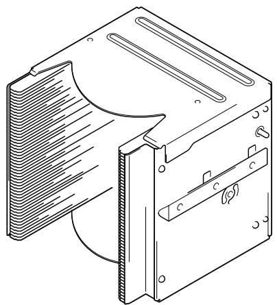
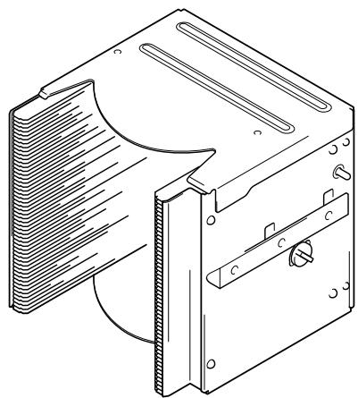
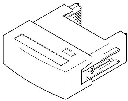
![PIONEER DRM-3000 - DVD-R/RW drive unit [DVD-R7322] - 1](/content/2019/11/118596/images/2688c3e238ade2885b82183b6dbb460baff700e1272b61bf1fa6b0e339d04587.jpg)
![PIONEER DRM-3000 - DVD-ROM drive unit [DVD-D7563] - 1](/content/2019/11/118596/images/5acf020ea375a9153096785a3554009c7b153d7e19d90dcf0abc46730a9d6a97.jpg)
![PIONEER DRM-3000 - DVD-ROM drive unit [DVD-D7563] - 2](/content/2019/11/118596/images/3dd813729876e7816aac4cdf5fa838eb591698303b1819cb28b0650db4c9bfff.jpg)