
SPM-K30 - Flat screen mount YAMAHA - Free user manual and instructions
Find the device manual for free SPM-K30 YAMAHA in PDF.


| Product Type | Wall mount for flat screen |
| Brand | Yamaha |
| Model | SPM-K30 |
| VESA Compatibility | 100x100 mm to 400x400 mm |
| Maximum Load Capacity | 30 kg |
| Material | Robust steel |
| Color | Black |
| Bracket Dimensions | 500 x 200 x 30 mm (approx) |
| Bracket Weight | 1.8 kg |
| Tilt | -5° to +15° |
| Swivel | ±90° |
| Wall Distance | 50 to 400 mm |
| Built-in Spirit Level | Yes |
| Wall Fixings Included | Anchors and screws supplied |
| Main Functions | Wall mounting, tilt, swivel, leveling |
| Care and Cleaning | Wipe with a soft dry cloth. Do not use abrasive cleaners. |
| Safety | Check wall solidity before installation. Do not exceed maximum load. |
| Spare Parts and Repairability | Spare parts available via Yamaha after-sales service. |
| Warranty | 2 years |
| General Information | Bracket designed for flat screens LCD, LED, OLED. |
Frequently Asked Questions - SPM-K30 YAMAHA
User questions about SPM-K30 YAMAHA
0 question about this device. Answer the ones you know or ask your own.
Ask a new question about this device
Download the instructions for your Flat screen mount in PDF format for free! Find your manual SPM-K30 - YAMAHA and take your electronic device back in hand. On this page are published all the documents necessary for the use of your device. SPM-K30 by YAMAHA.
USER MANUAL SPM-K30 YAMAHA
Large wall mount bracket
Grand support mural
Große Wandhalterung
Small wall mount bracket
Petit support mural
Thank you very much for purchasing the Wall Mount Bracket SPM-K30. Be sure to read this manual thoroughly before using this bracket. After you have read this manual, retain it for future reference.
When installing the Digital Sound Projector using this bracket, all installation work must be performed by a qualified contractor or dealer personnel. The customer must never attempt to perform this installation work. Improper or inadequate installation could cause the Digital Sound Projector to fall, resulting in personal injury.
SAFETY INSTRUCTIONS
- Always follow the instructions set forth in this manual when installing the Digital Sound Projector using this bracket.
Improper or inadequate installation could cause the Digital Sound Projector to fall, resulting in personal injury.
- The installation must be secure enough to bear the weight of the Digital Sound Projector, the wall bracket and other hardware indefinitely, and must also be secure enough to withstand vibrations.
Improper or inadequate installation could cause the Digital Sound Projector to fall, resulting in personal injury.
- To ensure safety, all screws must be tightened securely.
Loose screws could cause the Digital Sound Projector to fall, resulting in personal injury.
- Make sure to leave adequate ventilation space around the unit to allow heat generated by the Digital Sound Projector to dissipate.
Failure to provide adequate space around the unit could cause the Digital Sound Projector to overheat internally, resulting in a fire.
- Never hang from the Digital Sound Projector or the wall bracket.
Hanging from the Digital Sound Projector or the wall bracket could cause the Digital Sound Projector or the wall bracket to fall, resulting in personal injury.
- Once the Digital Sound Projector is installed, safety checks should be conducted on a regular basis.
If the Digital Sound Projector is used over an extended period of time, screws can become loose and the installation can become weaker due to the passage of time, vibrations, etc.
ACCESSORIES
Check that all of the following parts are included.
Large wall mount bracket (LEFT) (x1)
Large wall mount bracket (RIGHT) (x1)
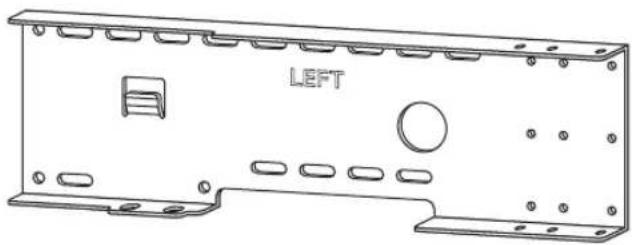
natural_image
Technical line drawing of a mechanical housing panel with labeled 'LEFT' component (no other text or symbols)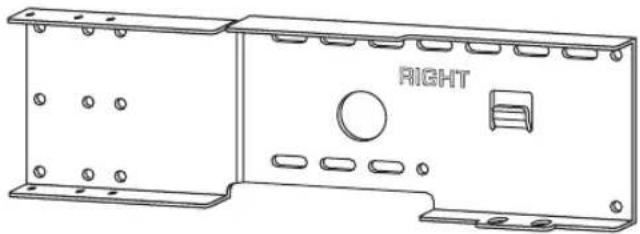
natural_image
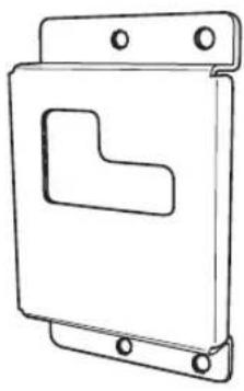
Technical line drawing of a mechanical housing or enclosure with mounting flanges and a central circular component labeled 'RIGHT' (no other text or symbols)Small wall mount brackets (Type A) (x2)

natural_image
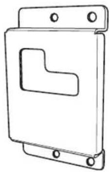
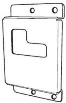
Technical line drawing of a mechanical bracket with mounting holes and a cutout (no text or symbols)Small wall mount brackets (Type B) (x2)

natural_image
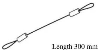
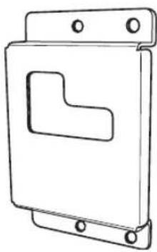
Technical line drawing of a mechanical component with mounting holes and a L-shaped cutout (no text or symbols)Safety wires (x2)
natural_image
Simple line drawing of a wire with two rectangular connectors, labeled 'Length 300 mm' at the bottom (no other text or symbols)Projector mounting screws (M6, 16 mm) (x6)

Projector mounting screws (M4, 10 mm) (x10)

Washers (for M6, 16 mm of outer circumference) (x4)

Note
Prepare at least six sets of commercially available tapping screws ( φ 4 mm, 25 mm or more in length) and washers in addition to the accessories shown above.
ASSEMBLING PROCEDURE
The dimensions after assembling the parts vary depending on the type of the Digital Sound Projector. Check the positions of the screw holes before assembling the parts.
YSP-800, YSP-900

YSP-3000, YSP-30D, YSP-3050, HTY-7030

YSP-4000, YSP-40D, HTY-7040

INSTALLATION PROCEDURE
Make sure to leave adequate ventilation space around the unit and follow the instructions below. The illustrations used in each step are the examples of YSP-800 and YSP-900.
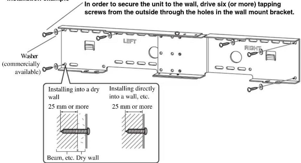
1 Attach the large wall mount bracket to the wall.
In order to secure the unit to the wall, you will need to attach the bracket to the wall first in a manner befitting the structure and quality of the wall.
Choose a location where the wall can bear the weight of the whole unit.
Before installing the bracket, make sure of the size (see "DIMENSIONS" on the first page of this manual).
Installation example
4 mm Tapping Screw (commercially available)
In order to secure the unit to the wall, drive six (or more) tapping screws from the outside through the holes in the wall mount bracket.
Note
Choose a secure wall or beam to fasten the screws. Do not install them into walls made of weak material that can easily come off, such as mortar or plywood wall panels. Loose screws could cause the projector to fall, resulting in personal injury.
2 Detach the metal apparatuses from the Digital Sound Projector. (Some models of YSP-800 only)
If the metal apparatuses are attached to the rear panel of your Digital Sound Projector, detach them from the rear left and right sides. If the metal apparatuses are not attached to the rear panel of your Digital Sound Projector, proceed to step 3.

3 Attach the small wall mount brackets to the Digital Sound Projector.
The small wall mount brackets vary depending on the type of the Digital Sound Projector. Refer to the following table for details on the type of the Digital Sound Projector and the compatible small wall mound brackets (Type A or B).
Use supplied projector mounting screws (M6 x 4 for YSP-4000, YSP-40D or HTY-7040 and M4 x 8 for other models) to securely attach the two small wall mount brackets to the rear left and right sides of the Digital Sound Projector.
| Digital Sound Projector | Small wall mount bracket |
| YSP-800YSP-900 | Type A |
| YSP-3000YSP-30DYSP-3050HTY-7030YSP-4000YSP-40DHTY-7040 | Type B |
Attach the brackets to the rear left and right sides of the Digital Sound Projector.
■ YSP-4000/YSP-40D/HTY-7040

■ YSP-3000/YSP-30D/HTY-7030/YSP-3050
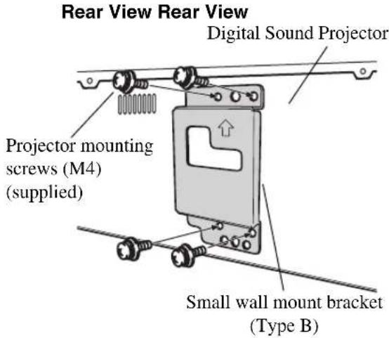
■ YSP-800/YSP-900

Notes
- In the unit of the model that the metal apparatuses are not attached, there are felt covers in the holes. In this case, tighten the screws to puncture the felt covers.
- If you tighten the screws on the slant, the screw threads in the projector might be broken. Be careful when using electric tools.
4 Attach the safety wire.
Attach the safety wire to the small wall mount bracket to prevent the Digital Sound Projector from falling.

5 Mount the Digital Sound Projector on the wall.
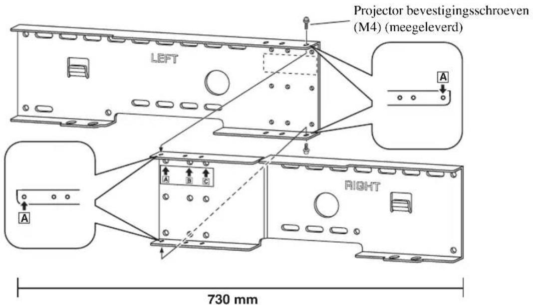
Fit the mounting guide hooks of the small wall mount brackets attached to the Digital Sound Projector into the holes on the left and right sides of the large wall mount bracket and then slide the unit to the right.
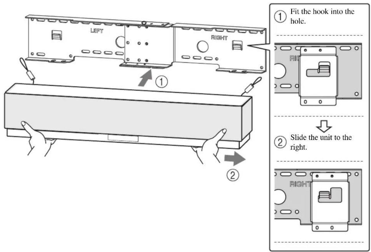
Note
Hold the Digital Sound Projector tight with both hands when attaching or removing the Digital Sound Projector to or from the wall. Holding the Digital Sound Projector loosely could cause the Digital Sound Projector to fall, resulting in personal injury.
6 Secure the unit.
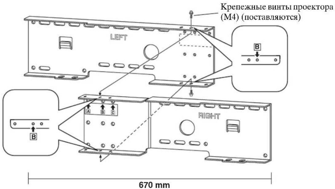
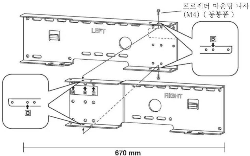
Align the holes in the large wall mount bracket with the holes in the bottom of the small wall mount brackets, and then use two of the supplied projector mounting screws (M6 x 16) to secure the unit. The positions of the screw holes vary depending on the type of the Digital Sound Projector. Refer to the following illustrations and check the correct positions of the screw holes used to secure your Digital Sound Projector.
■ YSP-800/YSP-900
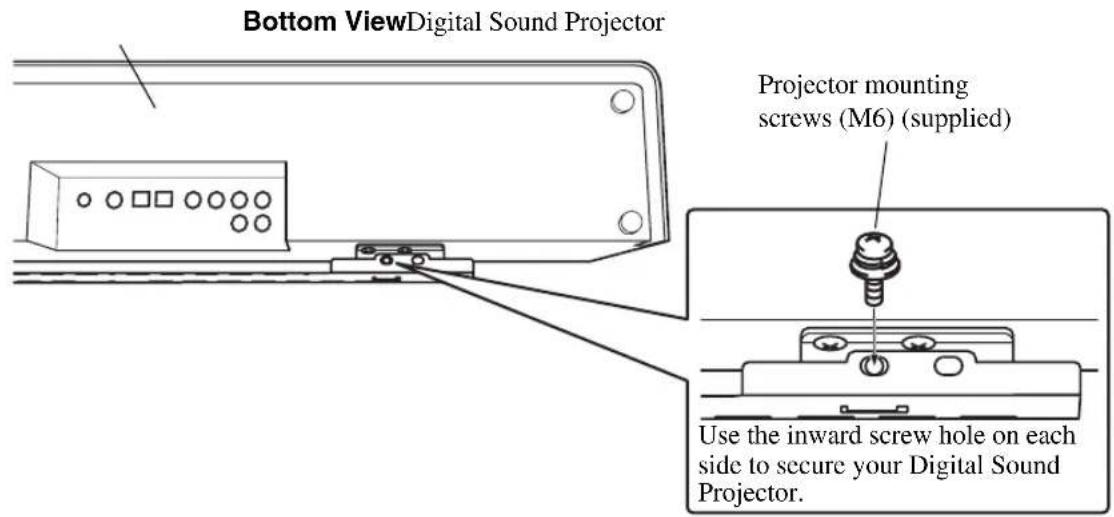
■ YSP-3000/YSP-30D/YSP-3050/HTY-7030/YSP-4000/YSP-40D/HTY-7040

7 Attach the safety wires to the wall.
Pass the screws (commercially available) through the loops of the safety wires and then tighten the screws to secure the safety wires to the wall.
Make sure that the screws are strong enough to bear the weight of the Digital Sound Projector and the brackets in case they fall.

Notes
- Attach the safety wires tight.
- Keep the 2 other washers for future use.
Limited Guarantee for European Economic Area (EEA) and Switzerland
Thank you for having chosen a Yamaha product. In the unlikely event that your Yamaha product needs guarantee service, please contact the dealer from whom it was purchased. If you experience any difficulty, please contact Yamaha representative office in your country. You can find full details on our website (www.yamaha-hifi.com/ or www.yamaha-uk.com/ for U.K. resident).
The product is guaranteed to be free from defects in workmanship or materials for a period of two years from the date of the original purchase. Yamaha undertakes, subject to the conditions listed below, to have the faulty product or any part(s) repaired, or replaced at Yamaha's discretion, without any charge for parts or labour. Yamaha reserves the right to replace a product with that of a similar kind and/or value and condition, where a model has been discontinued or is considered uneconomic to repair.
Conditions
- The original invoice or sales receipt (showing date of purchase, product code and dealer's name) MUST accompany the defective product, along with a statement detailing the fault. In the absence of this clear proof of purchase, Yamaha reserves the right to refuse to provide free of charge service and the product may be returned at the customer's expense.
- The product MUST have been purchased from an AUTHORISED Yamaha dealer within the European Economic Area (EEA) or Switzerland.
- The product must not have been the subject of any modifications or alterations, unless authorised in writing by Yamaha.
- The following are excluded from this guarantee:
a. Periodic maintenance and repair or replacement of parts due to normal wear and tear.
b. Damage resulting from:
(1) Repairs performed by the customer himself or by an unauthorised third party.
(2) Inadequate packaging or mishandling, when the product is in transit from the customer. Please note that it is the customer's responsibility to ensure the product is adequately packaged when returning the product for repair.
(3) Misuse, including but not limited to (a) failure to use the product for its normal purpose or in accordance with Yamaha's instructions on the proper use, maintenance and storage, and (b) installation or use of the product in a manner inconsistent with the technical or safety standards in force in the country where it is used.
(4) Accidents, lightning, water, fire, improper ventilation, battery leakage or any cause beyond Yamaha's control.
(5) Defects of the system into which this product is incorporated and/or incompatibility with third party products.
(6) Use of a product imported into the EEA and/or Switzerland, not by Yamaha, where that product does not conform to the technical or safety standards of the country of use and/or to the standard specification of a product sold by Yamaha in the EEA and/or Switzerland.
(7) Non AV (Audio Visual) related products.
(Products subject to "Yamaha AV Guarantee Statement" are defined in our website at www.yamaha-hifi.com/ or www.yamaha-uk.com/ for U.K. resident.)
- Where the guarantee differs between the country of purchase and the country of use of the product, the guarantee of the country of use shall apply.
- Yamaha may not be held responsible for any losses or damages, whether direct, consequential or otherwise, save for the repair or replacement of the product.
- Please backup any custom settings or data, as Yamaha may not be held responsible for any alteration or loss to such settings or data.
- This guarantee does not affect the consumer's statutory rights under applicable national laws in force or the consumer's rights against the dealer arising from their sales/purchase contract.
SUPPORT MURAL
SPM-K30
Grand support mural (GAUCHE) (x1)

natural_image
Technical line drawing of a mechanical housing panel with labeled 'LEFT' component (no other text or symbols)Grand support mural (DROIT) (x1)

natural_image
Technical line drawing of a two-part metal enclosure with mounting holes and a central circular component labeled 'RIGHT' (no text or symbols beyond the label)Petits supports muraux (Type A) (x2)
natural_image
Technical line drawing of a mechanical bracket with mounting holes and a cutout (no text or symbols)Petits supports muraux (Type B) (x2)

natural_image
Technical line drawing of a mechanical component with mounting holes and a L-shaped cutout (no text or symbols)YSP-3000, YSP-30D, YSP-3050, HTY-7030

YSP-4000, YSP-40D, HTY-7040

natural_image
Technical line drawing of a mechanical housing or enclosure with labeled components (no text or symbols beyond 'LEFT' label)natural_image
Technical line drawing of a two-part mechanical housing with mounting flanges and a central circular component labeled 'RIGHT' (no text or symbols beyond the label)natural_image
Technical line drawing of a mechanical bracket or mounting plate with mounting holes and a cutout (no text or symbols)natural_image
Technical line drawing of a mechanical component with mounting holes and a highlighted L-shaped cutout (no text or symbols)YSP-3000, YSP-30D, YSP-3050, HTY-7030

YSP-4000, YSP-40D, HTY-7040

natural_image
Technical line drawing of a mechanical housing panel with labeled 'LEFT' component (no other text or symbols)natural_image
Technical line drawing of a two-part mechanical housing with mounting flanges and a central circular component labeled 'RIGHT' (no text or symbols beyond the label)natural_image
Technical line drawing of a mechanical bracket with mounting holes and a cutout (no text or symbols)natural_image
Technical line drawing of a mechanical component with mounting holes and a L-shaped cutout (no text or symbols)natural_image
Simple line drawing of a coiled cable or wire with two connectors, labeled 'Längd 300 mm' at the bottom (no other text or symbols)YSP-3000, YSP-30D, YSP-3050, HTY-7030

YSP-4000, YSP-40D, HTY-7040

natural_image
Technical line drawing of a mechanical housing panel with labeled 'LEFT' component (no other text or symbols)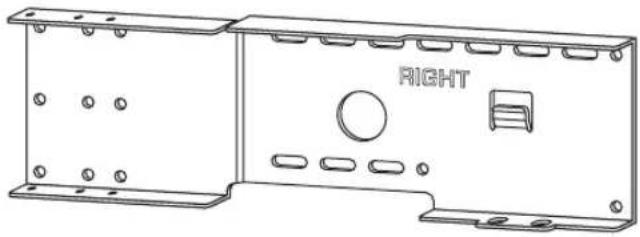
natural_image
Technical line drawing of a two-part metal enclosure with mounting holes and a central circular component labeled 'RIGHT' (no text or symbols beyond the label)natural_image
Technical line drawing of a mechanical bracket with mounting holes and a cutout (no text or symbols)natural_image
Technical line drawing of a mechanical bracket with mounting holes and a cutout (no text or symbols)YSP-3000, YSP-30D, YSP-3050, HTY-7030

YSP-4000, YSP-40D, HTY-7040

natural_image
Technical line drawing of a mechanical housing panel with labeled 'LEFT' component (no other text or symbols)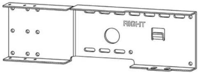
natural_image
Technical line drawing of a two-part mechanical housing with mounting flanges and a central circular component labeled 'RIGHT' (no text or symbols beyond the label)natural_image
Technical line drawing of a mechanical bracket with mounting holes and a cutout (no text or symbols)natural_image
Technical line drawing of a mechanical component with mounting holes and a L-shaped cutout (no text or symbols)YSP-3000, YSP-30D, YSP-3050, HTY-7030

YSP-4000, YSP-40D, HTY-7040

natural_image
Technical line drawing of a mechanical housing panel with labeled 'LEFT' component (no other text or symbols)
natural_image
Technical line drawing of a two-part metal enclosure with mounting flanges and a central circular component labeled 'RIGHT' (no text or symbols beyond label)Kleine wandbevestigingsbeugels (Type A) (x2)
natural_image
Technical line drawing of a mechanical bracket with mounting holes and a cutout (no text or symbols)Kleine wandbevestigingsbeugels (Type B) (x2)

natural_image
Technical line drawing of a mechanical component with mounting holes and a L-shaped cutout (no text or symbols)natural_image
Simple line drawing of a coiled cable or wire with two connectors, labeled 'Lengte 300 mm' at the bottom (no other text or symbols)Projector bevestigingsschroeven (M6, 16 mm) (x6)

Projector bevestigingsschroeven (M4, 10 mm) (x10)

YSP-3000, YSP-30D, YSP-3050, HTY-7030

YSP-4000, YSP-40D, HTY-7040
INSTALLATIEPROCEDURE
natural_image
Technical line drawing of a mechanical housing panel with labeled 'LEFT' component (no other text or symbols)
natural_image
Technical line drawing of a two-part mechanical housing with mounting flanges and a central circular component labeled 'RIGHT' (no text or symbols beyond the label)natural_image
Technical line drawing of a mechanical bracket with mounting holes and a cutout (no text or symbols)natural_image
Technical line drawing of a mechanical component with mounting holes and a L-shaped cutout (no text or symbols)YSP-3000, YSP-30D, YSP-3050, HTY-7030
YSP-4000, YSP-40D, HTY-7040

natural_image
Technical line drawing of a mechanical housing panel with labeled 'LEFT' component (no other text or symbols)
natural_image
Technical line drawing of a two-part metal enclosure with mounting brackets and a central circular component labeled 'RIGHT' (no text or symbols beyond label)小挂壁托架
(A 型) (2 件)
natural_image
Technical line drawing of a mechanical bracket with mounting holes and a cutout (no text or symbols)小挂壁托架
(B型) (2件)

natural_image
Technical line drawing of a mechanical component with mounting holes and a L-shaped cutout (no text or symbols)安全金属线 (2 条)

YSP-3000, YSP-30D, YSP-3050, HTY-7030

YSP-4000, YSP-40D, HTY-7040

安装顺序
natural_image
Technical line drawing of a mechanical housing panel with labeled 'LEFT' component (no other text or symbols)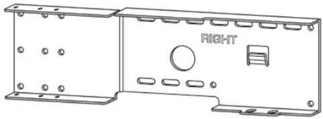
natural_image
Technical line drawing of a two-part metal enclosure with mounting holes and a central circular component labeled 'RIGHT' (no text or symbols beyond label)natural_image
Technical line drawing of a mechanical bracket with mounting holes and a cutout (no text or symbols)natural_image
Technical line drawing of a mechanical component with mounting holes and a highlighted L-shaped feature (no text or symbols)안전 와이어 (2 개)

YSP-3000, YSP-30D, YSP-3050, HTY-7030
YSP-4000, YSP-40D, HTY-7040

natural_image
Technical line drawing of a mechanical housing panel with labeled components (LEFT, circular hole, and mounting holes), no readable text or symbols beyond the label.
natural_image
Technical line drawing of a metal enclosure with mounting holes and a central circular component labeled 'RIGHT' (no other text or symbols)壁掛け金具(小)
A タイプ (× 2)
壁掛け金具(小)
B タイプ (× 2)
落下防止用ワイヤー
(× 2)
natural_image
Technical line drawing of a mechanical bracket with mounting holes and a cutout (no text or symbols)
natural_image
Technical line drawing of a mechanical component with mounting holes and a highlighted L-shaped cutout (no text or symbols)
natural_image
Simple line drawing of a cable with two connectors and a 300m length label (no other text or symbols)M6、16mm
(× 6)
取付ネジ
M4、10mm
取付ネジ
(× 10)
M6 用、外径 16mm
ワッシャー (× 4)


ご注意
©2007 YAMAHA CORPORATION All rights reserved.
- SAFETY INSTRUCTIONS
- ACCESSORIES
- Note
- ASSEMBLING PROCEDURE
- YSP-800, YSP-900
- YSP-3000, YSP-30D, YSP-3050, HTY-7030
- YSP-4000, YSP-40D, HTY-7040
- INSTALLATION PROCEDURE
- Attach the large wall mount bracket to the wall.
- Detach the metal apparatuses from the Digital Sound Projector. (Some models of YSP-800 only)
- Attach the small wall mount brackets to the Digital Sound Projector.
- Notes
- Attach the safety wire.
- Mount the Digital Sound Projector on the wall.
- Secure the unit.
- ■ YSP-800/YSP-900
- ■ YSP-3000/YSP-30D/YSP-3050/HTY-7030/YSP-4000/YSP-40D/HTY-7040
- Attach the safety wires to the wall.
- Limited Guarantee for European Economic Area (EEA) and Switzerland
- Conditions
- SUPPORT MURAL
- SPM-K30
- INSTALLATIEPROCEDURE
- 安装顺序
- ご注意
Brand : YAMAHA
Model : SPM-K30
Category : Flat screen mount