PDP-42MVE1 - TV PIONEER - Free user manual and instructions
Find the device manual for free PDP-42MVE1 PIONEER in PDF.

User questions about PDP-42MVE1 PIONEER
0 question about this device. Answer the ones you know or ask your own.
Ask a new question about this device
Download the instructions for your TV in PDF format for free! Find your manual PDP-42MVE1 - PIONEER and take your electronic device back in hand. On this page are published all the documents necessary for the use of your device. PDP-42MVE1 by PIONEER.
USER MANUAL PDP-42MVE1 PIONEER
Operating Instructions
Mode d'emploi
Bedienungsanleitung
Operating Instructions
Thank you very much for purchasing this PIONEER product. Before using your Plasma Display, please carefully read the "Important Information" and these "Operating Instructions" so you will know how to operate the Plasma Display properly. Keep this manual in a safe place. You will find it useful in the future.
Notes on Installation Work:
This product is marketed assuming that it is installed by qualified personnel with enough skill and competence. Always have an installation specialist or your dealer install and set up the product. PIONEER cannot assume liabilities for damage caused by mistake in installation or mouting, misuse, modification or a natural disaster.
Note for Dealers:
After installation, be sure to deliver this manual to the customer and explain to the customer how to handle the product.
Precautions
Please read this manual carefully before using your plasma monitor and keep the manual handy for future reference.
CAUTION

RISK OF ELECTRIC SHOCK DO NOT OPEN

CAUTION: TO REDUCE THE RISK OF ELECTRIC SHOCK, DO NOT REMOVE COVER. NO USER-SERVICEABLE PARTS INSIDE. REFER SERVICING TO QUALIFIED SERVICE PERSONNEL.

This symbol warns the user that uninsulated voltage within the unit may have sufficient magnitude to cause electric shock. Therefore, it is dangerous to make any kind of contact with any part inside of this unit.

This symbol alerts the user that important literature concerning the operation and maintenance of this unit has been included. Therefore, it should be read carefully in order to avoid any problems.
WARNING
TO PREVENT FIRE OR SHOCK HAZARDS, DO NOT EXPOSE THIS UNIT TO RAIN OR MOISTURE. ALSO DO NOT USE THIS UNIT'S POLARIZED PLUG WITH AN EXTENSION CORD RECEPTACLE OR OTHER OUTLETS, UNLESS THE PRONGS CAN BE FULLY INSERTED. REFRAIN FROM OPENING THE CABINET AS THERE ARE HIGH-VOLTAGE COMPONENTS INSIDE. REFER SERVICING TO QUALIFIED SERVICE PERSONNEL.
Warnings and Safety Precaution
This plasma monitor is designed and manufactured to provide long, trouble-free service. No maintenance other than cleaning is required. Please see the section "Plasma monitor cleaning procedure" on the next page.
The plasma display panel consists of fine picture elements (cells) with more than 99.99 percent active cells. There may be some cells that do not produce light or remain lit.
For operating safety and to avoid damage to the unit, read carefully and observe the following instructions. To avoid shock and fire hazards:
- Provide adequate space for ventilation to avoid internal heat build-up. Do not cover rear vents or install the unit in a closed cabinet or shelves.
If you install the unit in an enclosure, make sure there is adequate space at the top of the unit to allow hot air to rise and escape. If the monitor becomes too hot, the overheat protector will be activated and the monitor will be turned off. If this happens, turn off the power to the monitor and unplug the power cord. If the room where the monitor is installed is particularly hot, move the monitor to a cooler location, and wait for 60 minutes to cool the monitor. If the problem persists, contact your dealer for service.
- Do not use this unit's polarized plug with extension cords or outlets unless the prongs can be completely inserted.
- Do not expose the unit to water or moisture.
- Avoid damage to the power cord, and do not attempt to modify the power cord.
- Unplug the power cord during electrical storms or if the unit will not be used over a long period.
- Do not open the cabinet which has potentially dangerous high voltage components inside. If the unit is damaged in this way the warranty will be void. Moreover, there is a serious risk of electric shock.
- Do not attempt to service or repair the unit. The manufacturer is not liable for any bodily harm or damage caused if unqualified persons attempt service or open the back cover. Refer all service to authorized Service Centers.
NOTE:
When you connect a computer to this monitor, use an RGB cable including the ferrite core on both ends of the cable.
And regarding DVI and power cable, attach the supplied ferrite cores. If you do not do this, this monitor will not conform to mandatory CE or C-Tick standards.
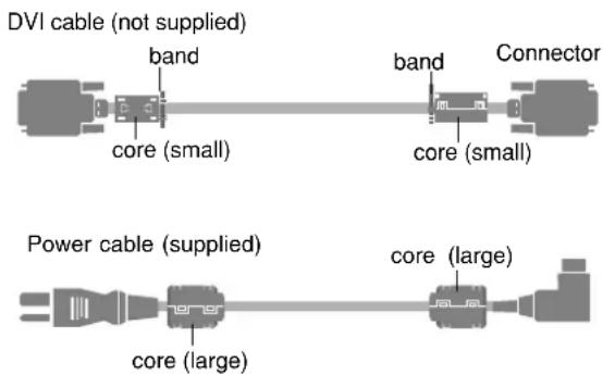
Attaching the ferrite cores:
Set the ferrite cores on both ends of the DVI cable (not supplied), and both ends of the power cable (supplied).
Close the lid tightly until the clamps click.
Use the band to fasten the ferrite core (supplied) to the DVI cable.
text_image
DVI cable (not supplied) band core (small) band core (small) Connector Power cable (supplied) core (large) core (large)To avoid damage and prolong operating life:
- Use only with 100-240 V 50/60Hz AC power supply. Continued operation at line voltages greater than 100-240 Volts AC will shorten the life of the unit, and might even cause a fire hazard.
- Handle the unit carefully when installing it and do not drop.
- Set the unit away from heat, excessive dust, and direct sunlight.
- Protect the inside of the unit from liquids and small metal objects. In case of accident, unplug the power cord and have it serviced by an authorized Service Center.
- Do not hit or scratch the panel surface as this causes flaws on the surface of the screen.
- For correct installation and mounting it is strongly recommended to use a trained, authorized dealer.
- As is the case with any phosphor-based display (like a CRT monitor, for example) light output will gradually decrease over the life of a Plasma Display Panel.
- To avoid sulfurization it is strongly recommended not to place the unit in a dressing room in a public bath or hot spring bath.
- Do not use in a moving vehicle, as the unit could drop or topple over and cause injuries.
- Do not place the unit on its side, upside-down or with the screen facing up or down, to avoid combustion or electric shock.
Plasma monitor cleaning procedure:
- Use a wiping cloth (attached) or a soft dry cloth to clean the front panel and bezel area. Never use solvents such as alcohol or thinner to clean these surfaces.
-
Clean plasma ventilation areas with a vacuum cleaner with a soft brush nozzle attachment.
-
To ensure proper ventilation, cleaning of the ventilation areas must be carried out monthly. More frequent cleaning may be necessary depending on the environment in which the plasma monitor is installed.
Recommendations to avoid or minimize phosphor burn-in: Like all phosphor-based display devices and all other gas plasma displays, plasma monitors can be susceptible to phosphor burn under certain circumstances. Certain operating conditions, such as the continuous display of a static image over a prolonged period of time, can result in phosphor burn if proper precautions are not taken. To protect your investment in this plasma monitor, please adhere to the following guidelines and recommendations for minimizing the occurrence of image burn:
* Always enable and use your computer's screen saver function during use with a computer input source.
* Display a moving image whenever possible.
* Change the position of the menu display from time to time.
* Always power down the monitor when you are finished using it.
If the plasma monitor is in long term use or continuous operation take the following measures to reduce the likelihood of phosphor burn:
* Lower the Brightness and Contrast levels as much as possible without impairing image readability.
* Display an image with many colors and color gradations (i.e. photographic or photo-realistic images).
* Create image content with minimal contrast between light and dark areas, for example white characters on black backgrounds. Use complementary or pastel color whenever possible.
* Avoid displaying images with few colors and distinct, sharply defined borders between colors.
* Note: Burn-in is not covered by the warranty.
Contact your dealer for other recommended procedures that will best suit your particular application needs.
CAUTION:
WHEN POSITIONING THIS EQUIPMENT ENSURE THAT THE MAINS PLUG AND SOCKET IS EASILY ACCESSIBLE.
This product complies with the Low Voltage Directive (73/23/EEC, amended by 93/68/EEC), EMC Directives (89/336/EEC, amended by 92/31/EEC and 93/68/EEC).
Caution
This model is for use with the following optional accessories. Use with other optional accessories is capable of resulting in instability causing possible injury.
Speakers: PDP-S32-LR
Table top stand: PDK-TS09
Wall mount unit: PDK-WM04
Tilt mount unit: PDK-WT01
Ceiling mount unit: PDK-CK01
Installation 2
Ventilation Requirements for enclosure mounting ..... 2
How to use the safety metal fittings and the screws for safety metal fittings 2
Creating a video wall 3
Cable Management.... 3
Caution on when the plasma monitor is installed vertically ... 4
How to use the remote control.... 4
Battery Installation and Replacement 4
Using the wired remote control mode .... 4
Operating Range 4
Handling the remote control 4
Part Names and Function .... 5
Front View 5
Rear View/ Terminal Board 6
Remote Control 7
Basic Operations 8
POWER 8
To turn the unit ON and OFF: 8
VOLUME 8
To adjust the sound volume: 8
MUTING 8
To mute the sound: 8
DISPLAY 8
To check the settings: 8
DIGITAL ZOOM 8
AUTO SET UP 8
To adjust the size or quality of the picture automatically: .....8
OFF TIMER 8
To set the off timer: 8
To check the remaining time: 8
To cancel the off timer: 8
WIDE Operations 9
SCREEN SIZE Operation (manual) 9
When viewing videos or digital video discs 9
SCREEN SIZE Operation with Computer Signals ..... 10
OSD (On Screen Display) Controls 11
Menu Operations 11
Setting the language for the menus 11
Menu Tree 12
Picture Settings Menu.... 14
Adjusting the picture 14
Setting the picture modes according to the brightness of the room 14
Reducing noise in the picture 14
Setting the color temperature 14
Adjusting the color to the desired level 15
Changing the Gamma Curve 15
Making the Low Tone adjustments 15
Adjusting the colors 15
SOUND Settings Menu 16
Adjusting the treble, bass and left/right balance and audio input select 16
Setting the allocation of the audio connectors ..... 16
SCREEN Settings Menu 16
Adjusting the Position, Size, PHASE, CLOCK ...... 16
Option1 Settings Menu 17
Setting the on-screen display 17
Setting the PC2/COMPONENT2 connectors ..... 17
Setting the PC1 connector 17
Setting a computer image to the correct RGB select screen ..... 18
Setting high definition images to the suitable screen size .... 18
Setting the Input Skip 18
Resetting to the default values 18
Option2 Settings Menu 19
Setting the power management for computer images. 19
STANDBY/ON indicator 19
Setting the picture to suit the movie 19
Reducing burn-in of the screen 19
Setting the gray level for the SIDE MASK 21
Setting the screen size for S1/S2 video input 22
Setting the signal and black level for DVI signal ..... 22
Option3 Settings Menu 22
Using the timer 22
Setting the power on mode 23
Enabling/disabling the front panel controls 23
Enabling/disabling remote control wireless transmission .... 24
Loop Out setting 24
ID number setting 24
Video Wall setting 24
Advanced OSD Settings Menu 27
Setting the menu mode 27
Color System Settings Menu 27
Setting the video signal format 27
Source Information Menu 27
Checking the frequencies, polarities of input signals, and resolution 27
Pin Assignments 28
mini D-Sub 15-pin connector (Analog) 28
DVI-D 24-pin connector (Digital) 28
Table of Signals Supported 29
Troubleshooting 31
Specifications 32
Contents of the Package
□ Plasma monitor
□ Power cord
□ Remote control with two AAA Batteries
□ Manual
□ Warranty
□ Safety metal fittings (2pcs)*
□ Ferrite cores (large 2pcs, small 2pcs)
□ Bands (2pcs)
□ Wiping cloth
* These are fittings for fastening the unit to a wall to prevent tipping due to external shock when using the stand (optional). Fasten the safety fittings to the holes in the back of the monitor using the safety fitting mount screws (see page 2).
Options
- Stand
- Speakers
- Wall mount unit
- Tilt mount unit
- Ceiling mount unit
You can attach your optional mounts or stand to the plasma monitor in one of the following two ways:
* While it is upright. (See Drawing A)
* As it is laid down with the screen face down (See Drawing B). Lay the protective sheet, which was wrapped around the monitor when it was packaged, beneath the screen surface so as not to scratch the screen face.
* Do not touch or hold the screen face when carrying the unit.
- This device cannot be installed on its own. Be sure to use a stand or original mounting unit. (Wall mount unit, Stand, etc.)
* See page 1. - For correct installation and mounting it is strongly recommended to use a trained, authorized dealer.
Failure to follow correct mounting procedures could result in damage to the equipment or injury to the installer.
Product warranty does not cover damage caused by improper installation.
* Use only the mounting kit or stand provided by manufacturer and listed under Options.

natural_image
3D illustration of a flat-screen monitor mounted on a base with a wavy pattern underneath (no text or symbols)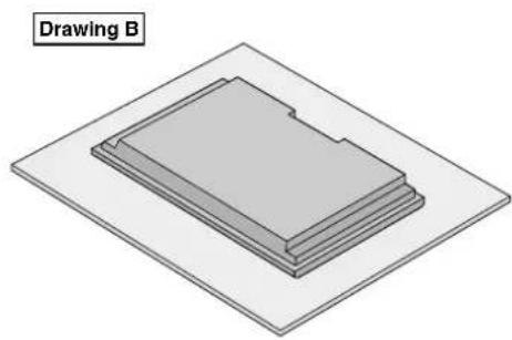
natural_image
3D diagram of a layered mechanical component labeled 'Drawing B' (no other text or symbols)Ventilation Requirements for enclosure mounting
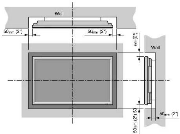
To allow heat to disperse, leave space between surrounding objects as shown on the diagram below when installing.
text_image
Wall 50mm (2") 50mm (2") mm (2') Wall 50mm (2") 50 50mm (2")How to use the safety metal fittings and the screws for safety metal fittings
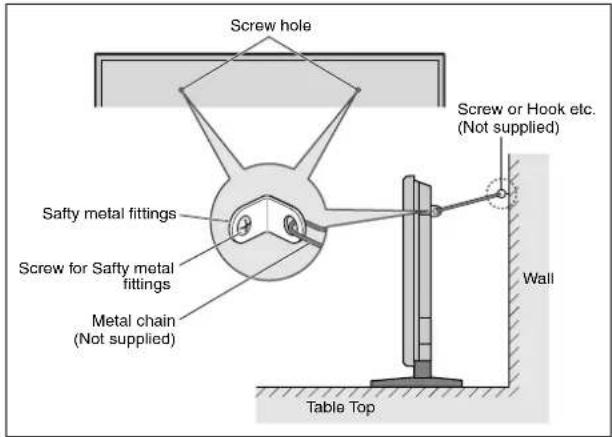
These are fittings for fastening the unit to a wall to prevent tipping due to external shock when using the stand (optional). Fasten the safety fittings to the holes in the back of the monitor using the safety fitting mount screws.
text_image
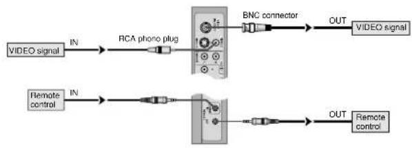
Screw hole Screw or Hook etc. (Not supplied) Safty metal fittings Screw for Safty metal fittings Metal chain (Not supplied) Wall Table TopCreating a video wall
With built-in matrix display capability, you can create a 4-25 video wall.
- Connect signal cables and remote cables as shown below.
Video signal PC/COMPONENT signal
flowchart
graph LR
    A["VIDEO signal"] -->|IN| B["RCA phono plug"]
    C["Remote control"] -->|IN| D["Analog device"]
    B --> D
    D --> E["BNC connector"]
    E --> F["OUT"]
    G["VIDEO signal"] --> H["Output"]
    I["Remote control"] --> J["Output"]

flowchart
graph LR
    A["PC signal/ COMPONENT signal"] -->|IN| B["BNC connector"]
    C["Remote control"] -->|IN| D["Switch"]
    B --> E["Switch"]
    D --> F["Switch"]
    E --> G["OUT"]
    F --> H["OUT"]
    G --> I["PC signal/ COMPONENT signal"]
    H --> J["Remote control"]
Note:
- The VIDEO1 and PC1 terminals can be used for either INPUT or OUTPUT.
When LOOP OUT is ON, do not connect an OUTPUT signal from another unit, that will place an extraordinary load on the other unit and may damage it. - LOOP OUT can not be turned ON while signals are input to the PCI terminal.
- LOOP OUT can be turned ON while signals are input to the PC1 terminal if the POWER is switched ON.
Information
• To loop signals out to another plasma display, set the LOOP OUT to ON.
• To create a video wall, set the VIDEO WALL menu items properly.
- To connect monitors, please use a 1\~2m (3.3\~6.6 feet) BNC cable (any commercially available cable).
- If the image quality is poor, do not use the monitor's out terminal. Use a distribution amplifier (any commercially available distribution amplifier) to connect the split signals to the respective monitor INPUT terminals.
- Being used as a video wall function, maximally 4-screen is rough-standard with lower than 1024 × 768 , 60Hz signal.
- A distribution amplifier is particularly recommended when using 9-screen and over video wall.
- From the second monitor onward, connections require a BNC-RCA conversion cable or connector, a mini D-Sub 15 pin cable-BNC (×5) cable or a conversion connector.
Cable Management
Using the cable clamps provided with the plasma display, bundle at the back of the unit the signal and audio cables connected to the display.

text_image
Back of the unit mounting hooksTo attach To detach
1.2.

text_image
clamp mounting hook

Caution on when the plasma monitor is installed vertically
- Use the optional unit. Contact your store of purchase when installing.
- Rotate 90^ clockwise as seen from the front when installing.
• After installing, check with the PIONEER logo mark as seen from the front. - Be sure to set "OSD ANGLE" to "V" when using.
* Failure to heed the above cautions may lead to malfunction.
How to use the remote control Battery Installation and Replacement
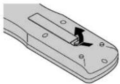
Insert the 2 "AAA" batteries, making sure to set them in with the proper polarity.
- Press and open the cover.
natural_image
Diagram of a remote control device with a black arrow pointing to a button (no text or symbols present)- Align the batteries according to the (+) and (−) indication inside the case.

natural_image
Technical illustration of a mechanical component with a highlighted internal slot (no text or symbols)- Replace the cover.

natural_image
Technical line drawing of a mechanical clamp or bracket component (no text or symbols)Using the wired remote control mode
Connect the remote cable* to the remote control's remote jack and the "REMOTE IN" terminal on the monitor.
When the cable is connected, the mode automatically switches to wired remote control. When the wired remote control mode is used, the remote control can be operated even if no batteries are loaded.

text_image
Remote Control Cable* To Remote Jack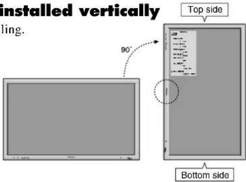
text_image
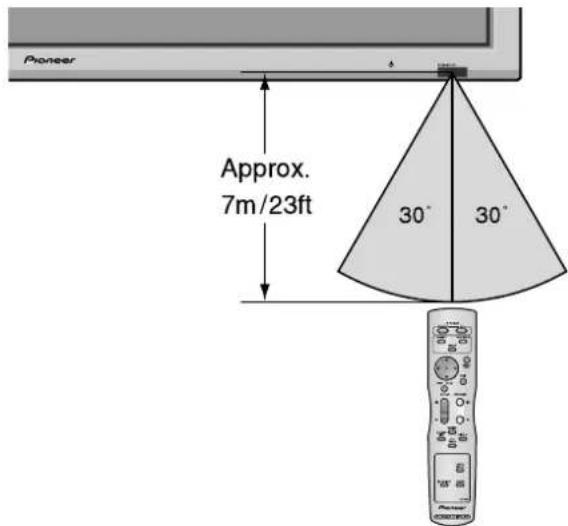
installed vertically ling. Top side 90° Bottom sideOperating Range
* Use the remote control within a distance of about 7 m/23ft. from the front of the monitor's remote control sensor and at horizontal and vertical angles of up to approximately 30°.
* The remote control operation may not function if the monitor's remote control sensor is exposed to direct sunlight or strong artificial light, or if there is an obstacle between the sensor and the remote control.
text_image
Pioneer Approx. 7m/23ft 30° 30°Handling the remote control
- Do not drop or mishandle the remote control.
- Do not get the remote control wet. If the remote control gets wet, wipe it dry immediately.
- Avoid heat and humidity.
- When not using the remote control for a long period, remove the batteries.
- Do not use new and old batteries together, or use different types together.
- Do not take apart the batteries, heat them, or throw them into a fire.
- When using the remote control in the wireless condition, be sure to unplug the remote cable from the REMOTE IN terminal on the monitor.
- When disposing of used batteries, please comply with governmental regulations or environmental public instruction's rules that apply in your country/area.
Part Names and Function
Front View

text_image
Pioneer MENU/SET VOLUME LEFT/- RIGHT/+ INPUT/EXIT 7 6 5 4 132 STANDBY/ON①Power ( ⏻
Turns the monitor's power on and off.
②Remote sensor window
Receives the signals from the remote control.
③STANDBY/ON indicator
When the power is on .... Lights green.
When the power is in the standby mode ... Lights red.
④INPUT/EXIT
Switches the input.
The available inputs depend on the setting of "BNC INPUT", "RGB SELECT", "D-SUB SELECT" and "DVI SET-UP".
Functions as the EXIT buttons in the On-Screen Display (OSD) mode.
⑤LEFT/- and RIGHT/+
Functions as the CURSOR (◀/▶) buttons in the On-Screen Display (OSD) mode.
⑥VOLUME ∨ and ∧
Adjusts the volume. Functions as the CURSOR (▲/▼) buttons in the On-Screen Display (OSD) mode.
⑦MENU/SET
Sets the On-Screen Display (OSD) mode and displays the main menu.
WARNING
The Power on/off switch does not disconnect the plasma display completely from the supply mains.
Note: This plasma monitor has the capacity to display images when connected to European DVD players with a SCART output signal, which is RGB with composite sync.
Your dealer can supply a special SCART cable, which will enable you to use the RGB with composite sync signal.
To obtain the special cable as well as for further information, please contact your dealer.
Please refer to page 19 for selection of the correct mode in the on-screen display.
Rear View/ Terminal Board
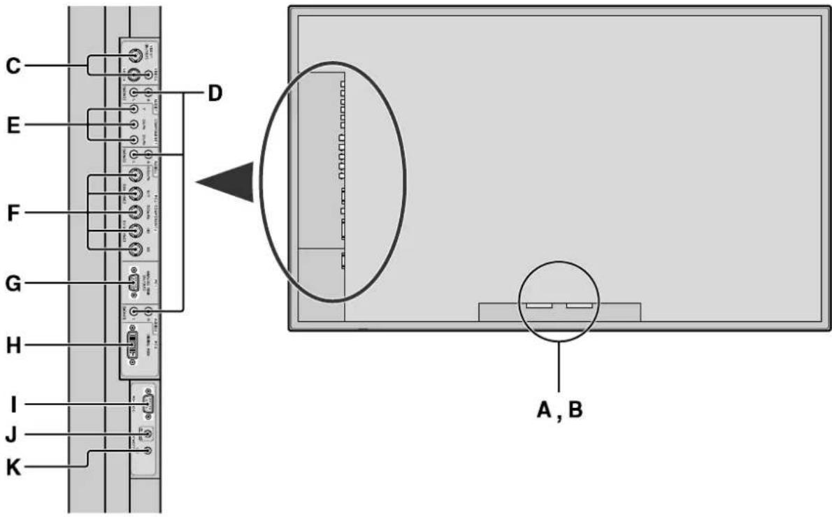
text_image
C E F G H I J K D A, BA AC IN
Connect the included power cord here.
B EXT SPEAKER L and R
Connect speakers (optional) here. Maintain the correct polarity. Connect the ⊕ (positive) speaker wire to the ⊕ EXT SPEAKER terminal and the ⊖ negative) speaker wire to the ⊖ EXT SPEAKER terminal on both LEFT and RIGHT channels. Please refer to your speaker's owner's manual.
C VIDEO1, 2, 3 (BNC, RCA, S-Video)
Connect VCR's, DVD's or Video Cameras, etc. here. VIDEO1 can be used for Input or Output (see page 24).
D AUDIO1, AUDIO2, AUDIO3
These are audio input terminals. The input is selectable. Set which video image to allot them from the SOUND menu screen.
E COMPONENT1
Connect DVD's, High Definition or Laser Discs, etc. here.
F PC2/COMPONENT2
PC2: You can connect an analog RGB signal and the synchronization signal. COMPONENT2: You can connect DVDs, High Definition sources, Laser Discs, etc. here. This input can be set for use with an RGB or component source (see page 17).
G PC1 (mini D-Sub 15pin)
Connect an analog RGB signal from a computer, etc. here. This input can be used for Input or Output (see page 24).
H PC3 (DV1 24pin)
Connect a digital signal (TMDS) from a source with a DVI output.
| RS-232C
Never connect any component to this connector without first consulting your Pioneer installation technician.
This connector is used for plasma display setup adjustments.
J REMOTE IN
Connect the remote cable* to the remote control's remote jack to obtain wired remote control.
K REMOTE OUT
Connect the remote cable* to the REMOTE IN jack of the other display monitor to obtain wired remote control.
Information
- For Y/CB/Cr, connect to the COMPONENT1 or PC2/COMPONENT2 terminals.
- For SCART, this unit provides three ways to connect:
· SCART1: Connect R/G/B and composite sync. to the PC2/COMPONENT2 terminals. (R, G, B and HD connector)
· SCART2: Connect R/G/B to the COMPONENT2 terminals and composite sync. to the VIDEO1 terminal.
· SCART3: Connect R/G/B and composite sync. to the PCI terminal.
Remote Control

text_image
1 2 3 4 5 6 7 8 9 10 11 12 13 14 15 16 Pioneer PLASMA DISPLAY POWER ON STANDBY RGB/PC COMPONENT VIDEO MENU/SET POINT ZOOM VOLUME ZOOM MUTING SCREEN DISPLAY OFF TIMER ID NO SET CLEAR AUTO SET UP AX01444① POWER ON/STANDBY
Switches the power on/standby. (This does not operate when STANDBY/ON indicator of the main unit is off.)
② RGB/PC
Press this button to select RGB/PC as the source. RGB/PC can also be selected using the INPUT/EXIT button on the monitor.
③ COMPONENT
Press this button to select COMPONENT as the source. COMPONENT can also be selected using the INPUT/EXIT button on the monitor.
④ VIDEO
Press this button to select VIDEO as the source.
$$ \boxed {\rightarrow \text {VIDEO1} \rightarrow \text {VIDEO2} \rightarrow \text {VIDEO3}} $$
VIDEO can also be selected using the INPUT/EXIT button on the monitor.
⑤ MENU/SET
Press this button to access the OSD controls. Press this button during the display of the main menu to go to the sub menu.
⑥ CURSOR (▲ / ▼ / ◀ / ▶)
Use these buttons to select items or settings and to adjust settings.
⑦ EXIT
Press this button to exit the OSD controls in the main menu. Press this button during the display of the sub menu to return to the previous menu.
8 POINT ZOOM
Press this button to display the pointer.
⑨ ZOOM (+ /−)
Enlarges or reduces the image.
⑩ VOLUME (+ /−)
Adjusts the sound volume.
⑪ MUTING
Mutes the sound.
⑫ SCREEN SIZE
Automatically detects the signal and sets the aspect ratio. SCREEN SIZE button is not active for all signals.
⑬ DISPLAY
Displays the source settings on the screen.
14 OFF TIMER
Activates the off timer for the unit.
⑮ AUTO SET UP
Press this button to adjust PHASE, CLOCK, Position, and Contrast automatically, or to switch the screen size to ZOOM mode automatically with the superimposed caption displayed fully only when the picture contains dark areas above and below the picture.
⑯ ID NO. SET
Set the ID number in the remote control. The remote control can then be used only for a display with the same ID number. When several displays are used together they can be controlled individually.
⑰ CLEAR
Clears the number set by the ID NO. SET button.
18 Remote control signal transmitter
Transmits the remote control signals.
19 Remote Jack
Insert the plug of the remote cable (The 1/8 Stereo Mini cable) here when using the supplied remote control in the wired condition.
POWER
To turn the unit ON and OFF:
- Plug the power cord into an active AC power outlet.
- Press the Power button (on the unit).
The monitor's STANDBY/ON indicator turns red and the standby mode is set. - Press the POWER ON button (on the remote control) to turn on the unit.
The monitor's STANDBY/ON indicator will light up (green) when the unit is on. - Press the POWER STANDBY button (on the remote control) or the Power button (on the unit) to turn off the unit.
The monitor's STANDBY/ON indicator turns red and the standby mode is set (only when turning off the unit with the remote control).
VOLUME
To adjust the sound volume:
- Press and hold the VOLUME ⭕ button (on the remote control or the unit) to increase to the desired level.
- Press and hold the VOLUME ⊖ button (on the remote control or the unit) to decrease to the desired level.
MUTING
To mute the sound:
Press the MUTING button on the remote control to mute the sound; press again to restore.
DISPLAY
To check the settings:
- The screen changes each time the DISPLAY button is pressed.
- If the button is not pressed for approximately three seconds, the menu turns off.
DIGITAL ZOOM
Digital zoom specifies the picture position and enlarges the picture.
- Press the POINT ZOOM button to display the pointer.

To change the size of the picture:
Press the ZOOM+ button and enlarge the picture.
The pointer will change to resemble a magnifying glass.
A press of the ZOOM- button will reduce the picture and return it to its original size.

To change the picture position:
Select the position with the ▲▼◀▶ buttons.
- Press the POINT ZOOM button to delete the pointer.
AUTO SET UP
To adjust the size or quality of the picture automatically:
Press the AUTO SET UP button.
Information
■ AUTO SET UP ON setting
When RGB (still picture) input is selected:
PHASE, CLOCK, Position, and Contrast will be adjusted automatically.
When RGB (motion picture), VIDEO, or Y/Pb/Pr (component) input is selected:
The screen size switches to ZOOM mode automatically with the superimposed caption displayed fully only when the picture contains dark areas above and below the picture.
OFF TIMER
To set the off timer:
The off timer can be set to turn the power off after 30, 60, 90 or 120 minutes.
-
Press the OFF TIMER button to start the timer at 30 minutes.
-
Press the OFF TIMER button to the desired time.
-
The timer starts when the menu turns off.

OFF TIMER 30
To check the remaining time:
- Once the off timer has been set, press the OFF TIMER button once.
- The remaining time is displayed, then turns off after a few seconds.
- When five minutes remain the remaining time appears until it reaches zero.
OFF TIMER 28
To cancel the off timer:
- Press the OFF TIMER button twice in a row.
- The off timer is canceled.
OFF TIMER 0
Note:
After the power is turned off with the off timer ... A slight current is still supplied to the monitor. When you are leaving the room or do not plan to use the system for a long period of time, turn off the power of the monitor.
SCREEN SIZE Operation (manual)
With this function, you can select one of six screen sizes.
When viewing videos or digital video discs
-
Press the SCREEN SIZE button on the remote control.
-
Within 3 seconds ...
Press the SCREEN SIZE button again.
The screen size switches as follows:

When a 720P or 1080I signal is input:
FULL 2.35:1
4:3 size screen
natural_image
Geometric pattern with intersecting circles and diagonal lines, no text or symbols presentThe normal size screen is displayed.
* The picture has the same size as video pictures with a 4:3 aspect ratio.
FULL size screen

natural_image
Geometric diagram with intersecting circles and diagonal lines inside a rectangle (no text or symbols)The image is expanded in the horizontal direction.
* Images compressed in the horizontal direction (“squeezed images”) are expanded in the horizontal direction and displayed on the entire screen with correct linearity. (Normal images are expanded in the horizontal direction.)
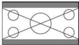
WIDE size screen

natural_image
Geometric pattern with a central circle and four surrounding circles, no text or symbols present.The picture is expanded in the horizontal and vertical directions at different ratios.
* Use this for watching normal video programs (4:3) with a wide screen.
ZOOM size screen

natural_image
Geometric diagram with concentric circles and semicircles, no text or symbols presentThe picture is expanded in the horizontal and vertical direction, maintaining the original proportions.
* Use this for theater size (wide) movies, etc.
2.35:1 size screen
Original image

natural_image
Pure geometric diagram with circles and diagonal lines inside a rectangle, no text or symbols presentInformation is lost on both sides.
The squeezed film image is expanded to fulfill the entire screen at a ratio of 2.35:1. Black bands do not appear at the top and bottom but information is lost on the left and right margins.
- This feature is available when the input signal is video, component (480I, 480P, 576I, 576P, 720P, 1080I) or RGB (525P or 625P signal from a scan converter).
* If black bands appear on the top and bottom in the full size screen, select the 2.35:1 size screen to avoid phosphor burn-in.
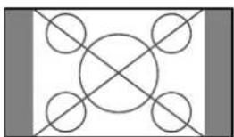
14:9 size screen

natural_image
Geometric diagram with a circle inscribed in a rectangle and two diagonal lines forming an X-shape (no text or symbols)The image is displayed at a 14:9 aspect ratio.
* This feature is available when the input signal is video, component (480I, 480P, 576I, 576P) or RGB (525P or 625P signal from a scan converter).
Note:
Do not allow the displayed in 4:3 mode or 14:9 mode for an extended period. This can cause a phosphor burn-in.
SCREEN SIZE Operation with Computer Signals
Switch to the wide screen mode to expand the 4:3 image to fill the entire screen.
- Press the SCREEN SIZE button on the remote control.
- Within 3 seconds ...
Press the SCREEN SIZE button again.
The screen size switches as follows:

4:3 size screen (4:3 or SXGA 5:4)

natural_image
Geometric pattern with intersecting circles and diagonal lines forming a symmetrical design (no text or symbols)The picture has the same size as the normal computer image.
FULL size screen

The image is expanded in the horizontal direction.
ZOOM size screen

natural_image
Geometric pattern with concentric circles and intersecting arcs inside a rectangle (no text or symbols)When wide signals are input.
FULL size screen

natural_image
Pure geometric diagram with intersecting lines and circles inside a rectangle (no text or symbols)Information
■ Supported resolution
See page 29 for details on the display output of the various VESA signal standards supported by the monitor.
■ When 852 (848) dot × 480 line wide VGA* signals with a vertical frequency of 60 Hz and horizontal frequency of 31.7 (31.0) kHz are input
Select an appropriate setting for RGB SELECT mode referring to the "Table of Signals Supported" on page 29.
* "VGA", "SVGA" and "SXGA" are registered trademarks of IBM, Inc. of the United States.
Note:
Do not allow the displayed in 4:3 mode or 14:9 mode for an extended period. This can cause a phosphor burn-in.
Menu Operations
The OSD window is displayed with respect to the screen as shown on the diagram.
* Depending on the screen's mode, the OSD may be displayed differently.
In the explanation, the OSD section is shown close up.
text_image
MAIN MEAT 1/2 INFORMATION SALADIS PICKERS EXP: 0.015 ADVANCED ODD . OKT B. RESTOPS GAIN: ADDENS EXITThe following describes how to use the menus and the selected items.
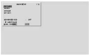
- Press the MENU/SET button on the remote control to display the MAIN MENU.
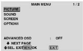
text_image
MAIN MENU 1 / 2 PICTURE SOUND SCREEN OPTION1 ADVANCED OSD : OFF ♦ NEXT PAGE ♦ SEL. EXIT MENU OK EXIT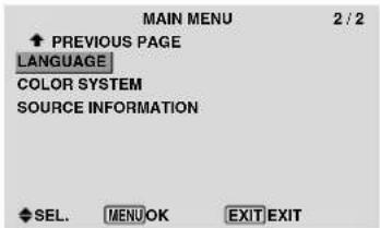
text_image
MAIN MENU 2 / 2 ◆ PREVIOUS PAGE LANGUAGE COLOR SYSTEM SOURCE INFORMATION ◆ SEL. MENU.OK EXIT.EXIT-
Press the cursor buttons ▲ ▼ on the remote control to highlight the menu you wish to enter.
-
Press the MENU/SET button on the remote control to select a sub menu or item.
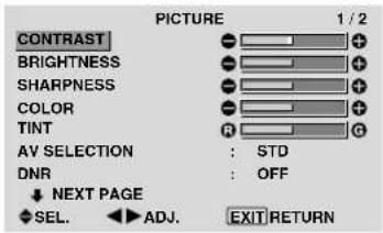
text_image
PICTURE 1 / 2 CONTRAST BRIGHTNESS SHARPNESS COLOR TINT AV SELECTION : STD DNR : OFF NEXT PAGE SEL. ▶ ADJ. EXIT RETURN-
Adjust the level or change the setting of the selected item by using the cursor buttons ◀ ▶ on the remote control.
-
The adjustments or the settings that are stored in memory. The change is stored until you change it again.
-
Repeat steps 2 - 5 to adjust an additional item, or press the EXIT button on the remote control to return to the main menu.
* When adjusting using the bar at the bottom of the screen, press the ◀or ▶ button within 5 seconds. If not, the current setting is set and the previous screen appears.
Note: The main menu disappears by pressing the EXIT button.
Information
■ Advanced menu mode
When “ADVANCED OSD” is set to “ON” in the main menu (1/2), full menu items will be shown.

text_image
MAIN MENU 1 / 2 PICTURE SOUND SCREEN OPTION1 OPTION2 OPTION3 ADVANCED OSD : ON ↓ NEXT PAGE ◆ SEL. MENU OK EXIT EXITSetting the language for the menus
The menu display can be set to one of seven languages.
Example: Setting the menu display to "DEUTSCH"
On "MAIN MENU", select "LANGUAGE", then press the MENU/SET button.
The "LANGUAGE" screen appears.
On "LANGUAGE", select "DEUTSCH", then press the MENU/SET button.

text_image
LANGUAGE LANGUAGE : DEUTSCH ADJ. MENU EXIT RETURNOKThe “LANGUAGE” is set to “DEUTSCH” and return to the main menu.
Information
■ Language settings
ENGLISH ..... English ITALIANO ..... Italian
DEUTSCH..... German SVENSKA ..... Swedish
FRANÇAIS ..... French РУССКИЙ.....Russian
ESPAÑOL .....Spanish
Menu Tree
:Shaded areas indicate the default value.
-←→+:Press the ◀ or ► button to adjust.
☐:Menu items in a ruled box are available when the ADVANCED OSD is set to ON.
| Main menu Sub menu Sub menu 2 Sub menu 3 Sub menu 4 RESET | REFERENCE | ||||||
| PICTURE | CONTRAST | -←→+ | 0←52→72 | YES | 14 | ||
| BRIGHTNESS | -←→+ | 0←32→64 | YES | 14 | |||
| SHARPNESS | -←→+ | 0←16→32 | YES | 14 | |||
| COLOR | -←→+ | 0←32→64 | YES | 14 | |||
| TINT | R←→G | 0←32→64 | YES | 14 | |||
| AV SELECTION DYNAMIC/STD/MOVIE1/MOVIE2/DEFAULT YES 14 | |||||||
| DNR | OFF/LOW/MID/HIGH | YES 14 | |||||
| COLOR TEMP. | LOW/MID LOW/MID/HIGH | YES 14 | |||||
| WHITE BALANCE | R.HIGH | -←→+ | 0←40→70 | YES | 15 | ||
| G.HIGH | -←→+ | 0←40→70 | YES | 15 | |||
| B.HIGH | -←→+ | 0←40→70 | YES | 15 | |||
| R.LOW | -←→+ | 0←40→70 | YES | 15 | |||
| G.LOW | -←→+ | 0←40→70 | YES | 15 | |||
| B.LOW | -←→+ | 0←40→70 | YES | 15 | |||
| RESET | OFF←→ON | YES | 15 | ||||
| GAMMA | 1←→2←···→4 | YES 15 | |||||
| LOW TONE | AUTO←→1←···→3 | YES 15 | |||||
| C. DETAIL ADJ | RED | Y←→M | 0←32→64 | YES | 15 | ||
| GREEN | C←→Y | 0←32→64 | YES | 15 | |||
| BLUE | M←→C | 0←32→64 | YES | 15 | |||
| YELLOW | G←→R | 0←32→64 | YES | 15 | |||
| MAGENTA | R←→B | 0←32→64 | YES | 15 | |||
| CYAN | B←→G | 0←32→64 | YES | 15 | |||
| RESET | OFF←→ON | YES | 15 | ||||
| Main menu Sub menu Sub menu 2 Sub menu 3 Sub menu 4 RESET | REFERENCE | |||
| SOUND | BASS | - +0 13 26 | YES | 16 |
| TREBLE | - +0 13 26 | YES | 16 | |
| BALANCE | L R-22 0 +22 | YES | 16 | |
| AUDIO INPUT1 | VIDEO 1-3 / COMPNT 1-2 / PC1DSUB / PC2-BNC / PC3-DVI | YES | 16 | |
| AUDIO INPUT2 | VIDEO 1-3 / COMPNT 1-2 / PC1DSUB / PC2-BNC / PC3-DVI | YES | 16 | |
| AUDIO INPUT3 | VIDEO 1-3 / COMPNT 1-2 / PC1DSUB / PC2-BNC / PC3-DVI | YES | 16 | |
| Main menu Sub menu Sub menu 2 Sub menu 3 Sub menu 4 RESET | REFERENCE | ||||
| SCREEN SCREEN SIZE 4:3/FULL/WIDE/ZOOM/2.35:1/14:9 | — | 16 | |||
| V.POSITION | -←→+ | -64←0→+64 | YES | 16 | |
| H.POSITION | -←→+ | -128←0→+127 | YES | 16 | |
| V.SIZE | -←→+ | 0←→64 | YES | 16 | |
| H.SIZE | -←→+ | 0←→64 | YES | 16 | |
| AUTO PICTURE | OFF←→ON*2 | NO | 16 | ||
| PHASE*1 | -←→+*2 | 0←→64 | YES 16 | ||
| CLOCK*1 | -←→+*2 | 0←64→128 | YES 16 | ||
| Main menu Sub menu Sub menu 2 Sub menu 3 Sub menu 4 RESET | REFERENCE | ||||
| OPTION1 | OSD | DISPLAY OSD | OFF←→ON | YES | 17 |
| OSD ADJUST | 1←⋯→6 | YES 17 | |||
| OSD ANGLE H←→V | YES 17 | ||||
| OSD ORBITER | OFF←→ON | YES | 17 | ||
| OSD CONTRAST | LOW←→NORMAL | YES | 17 | ||
| BNC INPUT | RGB←→COMP.←→SCART1←→SCART2 | YES | 17 | ||
| D-SUB INPUT | RGB←→SCART3 | — | 17 | ||
| RGB SELECT AUTO/STILL/MOTION/WIDE1/WIDE2/WIDE3/WIDE4/DTV | YES 18 | ||||
| HD SELECT | 1080B/1035I/1080A | NO | 18 | ||
| INPUT SKIP | OFF←→ON | YES | 18 | ||
| ALL RESET | OFF←→ON | — | 18 | ||
| Main menu Sub menu 2 Sub menu 3 Sub menu 4 RESET | REFERENCE | |||||
| OPTION2PWR. MGT. OFF←→ON YES 19 | ||||||
| PURECINEMA OFF←→ON YES 19 | ||||||
| LONG LIFE ABL AUTO/LOCK 1/LOCK 2/LOCK 3 YES 19 | ||||||
| ORBITER AUTO 1 YES 20 | ||||||
| AUTO 2 YES 20 | ||||||
| MANUAL H-DOT/V-LINE/TIME | YES 20 | |||||
| OFF | YES 20 | |||||
| INVERSE OFF | YES 20 | |||||
| ON | WORKING TIME/WAITING TIME | YES 20 | ||||
| WHITE | YES 20 | |||||
| SCREEN WIPER | OFF | YES 21 | ||||
| ON | WORKING TIME/WAITING TIME/SPEED | YES 21 | ||||
| SOFT FOCUS | OFF/1/2/3/4 | YES 21 | ||||
| SIDE MASK | 0←···→3←···→15 | YES 21 | ||||
| S1/S2 | AUTO←→OFF | YES | 22 | |||
| DVI SET-UP | PLUG/PLAY | PC←→STB/DVD | NO | 22 | ||
| BLACK LEVEL | LOW←→HIGH | NO | 22 | |||
Information
■ Restoring the factory default settings
Select "ALL RESET" under the OPTION1 menu. Note that this also restores other settings to the factory defaults.
Picture Settings Menu
Adjusting the picture
The contrast, brightness, sharpness, color and tint can be adjusted as desired.
Example: Adjusting the contrast
On "CONTRAST" of "PICTURE" menu, adjust the contrast.
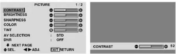
text_image
PICTURE 1/2 CONTRAST BRIGHTNESS SHARPNESS COLOR TINT AV SELECTION : STD DNR : OFF NEXT PAGE SEL. ▶ ADJ. EXIT RETURN CONTRAST 52Note: If "CAN NOT ADJUST" appears ...
When trying to enter the PICTURE submenu, make sure AV SELECTION is not set to DEFAULT.
Information
■ Picture adjustment screen
CONTRAST: Changes the picture's white level.
BRIGHTNESS: Changes the picture's black level.
SHARPNESS: Changes the picture's sharpness.
Adjusts picture detail of VIDEO display.
COLOR: Changes the color density.
TINT: Changes the picture's tint. Adjust for natural colored skin, background, etc.
■ Adjusting the computer image
Only the contrast and brightness can be adjusted when a computer signal is connected.
■ Restoring the factory default settings
Select "DEFAULT" under the "AV SELECTION" settings.
Setting the picture modes according to the brightness of the room
There are four picture modes that can be used effectively according to the environment in which you are viewing the display.
Example: Setting the "MOVIE 1" mode
On "AV SELECTION" of "PICTURE" menu, select "MOVIE 1".

text_image
PICTURE 1 / 2 CONTRAST BRIGHTNESS SHARPNESS COLOR TINT AV SELECTION : ← STD → DNR : OFF ← NEXT PAGE ← SEL. ← ADJ. EXIT RETURN AV SELECTION : ← MOVIE 1 →Information
■ Types of AV SELECTIONS
MOVIE 1, 2: Set this mode when watching video in a dark room.
This mode provides darker, finer pictures, like the screen in movie theaters.
For a darker image, select MOVIE 2.
STD: Set this mode when watching video in a bright room. This mode provides pictures with distinct differences between light and dark sections.
DYNAMIC: This mode provides brighter pictures than STD.
DEFAULT: Use this to reset the picture to the factory default settings.
Reducing noise in the picture
Use these settings if the picture has noise due to poor reception or when playing video tapes on which the picture quality is poor.
Example: Setting "HIGH"
On "DNR" of "PICTURE" menu, select "HIGH".

text_image
PICTURE 1/2 CONTRAST BRIGHTNESS SHARPNESS COLOR TINT AV SELECTION : STD DNR NEXT PAGE SEL. ADJ. EXIT RETURN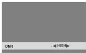
text_image
DNR : HIGHInformation
DNR
* "DNR" stands for Digital Noise Reduction. * This function reduces noise in the picture.
■ Types of noise reduction
There are three types of noise reduction. Each has a different level of noise reduction.
The effect increases stronger in the order of LOW, MID and High.
OFF: Turns the noise reduction function off.
Setting the color temperature
Use this procedure to set color tone produced by the plasma display.
Example: Setting "HIGH"
On "COLOR TEMP." of "PICTURE" menu, select "HIGH".

text_image
PICTURE 2 / 2 ↑ PREVIOUS PAGE COLOR TEMP. : HIGH GAMMA : 2 LOW TONE : AUTO C.DETAIL ADJ. ◆ SEL. ◀ ADJ. EXIT RETURNInformation
■ Setting the color temperature
LOW: Redder
MID LOW: Slightly red
MID: Standard (slightly bluer)
HIGH: Bluer
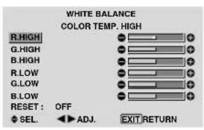
Adjusting the color to the desired level
Use this procedure to adjust the white balance for each color temperature to achieve the desired color quality.
Example: Adjusting the "R.HIGH" of "HIGH" color temperature
Set "ADVANCED OSD" to "ON" in the main menu (1/2), then perform the following operations.
On "COLOR TEMP." of "PICTURE" menu, select "HIGH", then press the MENU/SET button.
The "WHITE BALANCE" screen appears.
On "R.HIGH", adjust the white balance.
text_image
WHITE BALANCE COLOR TEMP. HIGH R.HIGH G.HIGH B.HIGH R.Low G.Low B.Low RESET : OFF SEL. ADJ. EXIT RETURN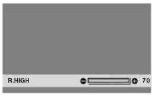
text_image
R.HIGH 70Information
■ Adjusting the white balance
R/G/B.HIGH: White balance adjustment for white level R/G/B.LOW: White balance adjustment for black level RESET: Resets settings to the factory default values.
Use ◀ and ▶ buttons to select "ON", then press the MENU/SET button.
■ Restoring the factory default settings
Select "RESET" under the WHITE BALANCE menu.
Changing the Gamma Curve
This feature adjusts the brightness of the midtone areas while keeping shadows and highlights unchanged.
Example: Setting "3"
Set "ADVANCED OSD" to "ON" in the MAIN MENU (1/2), then perform the following operations.
On "GAMMA" of "PICTURE" menu, select "3".

text_image
PICTURE 2 / 2 ↑ PREVIOUS PAGE COLOR TEMP. : MID GAMMA : 3 LOW TONE : AUTO C.DETAIL ADJ. SEL. ▶ ADJ. EXIT RETURNInformation
■ GAMMA settings
The picture becomes darker as the number increases (in the sequence of 1, 2, 3, 4).
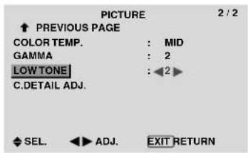
Making the Low Tone adjustments
This feature allows more detailed tone to be reproduced especially in the dark area.
Example: Setting "2"
Set "ADVANCED OSD" to "ON" in the MAIN MENU (1/2), then perform the following operations.
On "LOW TONE" of "PICTURE" menu, select "2".
text_image
PICTURE 2 / 2 ↑ PREVIOUS PAGE COLOR TEMP. : MID GAMMA : 2 LOW TONE : ◀2 ► C.DETAIL ADJ. ◆ SEL. ◀▶ ADJ. EXIT RETURNInformation
■ LOW TONE settings
AUTO: Will automatically appraise the picture and make adjustments.
1: Will apply the dither method suitable for still pictures.
2: Will apply the dither method suitable for motion pictures.
3: Will apply the error diffusion method.
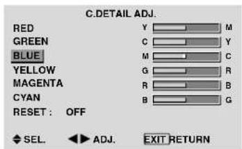
Adjusting the colors
Use this procedure to adjust hue and color density for red, green, blue, yellow, magenta and cyan.
You can accentuate the green color of trees, the blue of the sky, etc.
Example: Adjusting the color detail adj for blue
Set "ADVANCED OSD" to "ON" in the MAIN MENU (1/2), then perform the following operations.
On "PICTURE" menu, select "C. DETAIL ADJ", then press the MENU/SET button.
The "C. DETAIL ADJ" screen appears.
On "BLUE" of "C. DETAIL ADJ", adjust the color detail.
text_image
C.DDETAIL ADJ. RED Y M GREEN C Y BLUE M C YELLOW G R MAGENTA R B CYAN B G RESET: OFF SEL ADJ. EXIT RETURNInformation
C. DETAIL ADJ settings
RED: Makes red's adjustment
GREEN: Makes green's adjustment
BLUE: Makes blue's adjustment
YELLOW: Makes yellow's adjustment
MAGENTA: Makes magenta's adjustment
CYAN: Makes cyan's adjustment
RESET: Resets settings to the factory default value.
Use ◀ and ▶ buttons to select "ON", then press the MENU/SET button.
SOUND Settings Menu
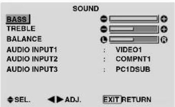
Adjusting the treble, bass and left/right balance and audio input select
The treble, bass and left/right balance can be adjusted to suit your tastes.
Example: Adjusting the bass
On "BASS" of "SOUND" menu, adjust the bass.
text_image
SOUND BASS TREBLE BALANCE AUDIO INPUT1 : VIDEO1 AUDIO INPUT2 : COMPNT1 AUDIO INPUT3 : PC1DSUB SEL. ADJ. EXIT RETURNNote : If "CAN NOT ADJUST" appears...
Set "AUDIO INPUT" on the SOUND menu correctly.
Information
■ SOUND settings menu
BASS: Controls the level of low frequency sound. TREBLE: Controls the level of high frequency sound. BALANCE: Controls the balance of the left and right channels.
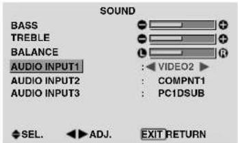
Setting the allocation of the audio connectors
Setting the AUDIO 1, 2, and 3 connectors to the desired input.
Example: Setting "AUDIO INPUT1" to "VIDEO 2"
On "AUDIO INPUT1" of "SOUND" menu, select "VIDEO2".
The available sources depend on the settings of input.
text_image
SOUND BASS TREBLE BALANCE AUDIO INPUT1 AUDIO INPUT2 AUDIO INPUT3 VIDEO2 COMPNT1 PC1DSUB SEL. ADJ. EXIT RETURNInformation
AUDIO INPUT
A single audio input cannot be selected as the audio channel for more than one input terminal.
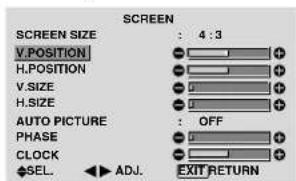
SCREEN Settings Menu
Adjusting the Position, Size, PHASE, CLOCK
The position of the image can be adjusted and flickering of the image can be corrected.
Example: Adjusting the vertical position in the normal mode
On "V.POSITION" of "SCREEN" menu, adjust the position.
The mode switches as follows each time the ◀or ► button is pressed:
4:3 ↔ FULL
* The mode can also be switched by pressing the SCREEN SIZE button on the remote control.
* The settings on the SCREEN menu are not preset at the factory.
text_image
SCREEN SCREEN SIZE : 4 : 3 V POSITION H POSITION V SIZE H SIZE AUTO PICTURE : OFF PHASE CLOCK SEL. ▶ ADJ. EXIT RETURN
text_image
V.POSITION +64Information
■ When "AUTO PICTURE" is "OFF"

text_image
SCREEN SCREEN SIZE :When Auto Picture is off, the PHASE and the CLOCK items are displayed so that you can adjust them.
■ Adjusting the Auto Picture
ON: The CLOCK, PHASE and Position adjustments are made automatically.
Not available for digital ZOOM.
OFF: The CLOCK, PHASE and Position adjustments are made manually.
* If PHASE can't be adjusted, set Auto Picture to OFF and adjust manually.
■ Adjusting the position of the image
V. POSITION: Adjusts the vertical position of the image.
H. POSITION: Adjusts the horizontal position of the image.
V.SIZE: Adjusts the vertical size of the image. (Except for WIDE mode)
H.SIZE: Adjusts the horizontal size of the image. (Except for WIDE mode)
PHASE*: Adjusts for flickering.
CLOCK*: Adjusts for striped patterns on the image.
* The CLOCK and PHASE features are available only when the "Auto Picture" is off.
* The AUTO PICTURE, PHASE and CLOCK are available only for RGB signals.
But, these features are not available for moving pictures on RGB, VIDEO or COMPONENT.
Option1 Settings Menu
Setting the on-screen display
This sets the position of the menu, the display format (horizontal or vertical) etc.
Example: Turning the DISPLAY OSD off
On "OPTION1" menu, select "OSD", then press the MENU/SET button.
The "OSD" menu appears.
On "DISPLAY OSD" of "OSD" menu, select "OFF".
text_image
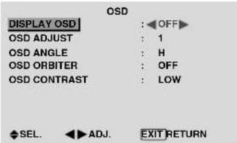
OSD DISPLAY OSD : OFF OSD ADJUST : 1 OSD ANGLE : H OSD ORBITER : OFF OSD CONTRAST : LOW SEL. ADJ. EXIT RETURNInformation
■ DISPLAY OSD settings
ON: The informations on screen size, volume control, etc. will be shown.
OFF: The informations on screen size, volume control, etc. will not be shown.
The DISPLAY button on the remote control will not function either.
■ OSD ADJUST settings
Adjusts the position of the menu when it appears on the screen.
The position can be set between 1 to 6.
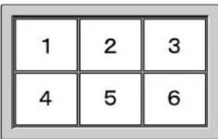
text_image
1 2 3 4 5 6■ OSD ANGLE settings
Sets the display format (landscape "H" or portrait "V"). When the unit is installed vertically set the OSD ANGLE at "V".
“H”
text_image
MODEL MODEL1: 0.07.001 MODEL1: 0.07.002 MODEL1: 0.07.003 MODEL1: 0.07.004 MODEL1: 0.07.005 MODEL1: 0.07.006 MODEL1: 0.07.007 MODEL1: 0.07.008 MODEL1: 0.07.009 MODEL1: 0.07.010 MODEL1: 0.07.011 MODEL1: 0.07.012 MODEL1: 0.07.013 MODEL1: 0.07.014 MODEL1: 0.07.015 MODEL1: 0.07.016 MODEL1: 0.07.017 MODEL1: 0.07.018 MODEL1: 0.07.019 MODEL1: 0.07.020 MODEL1: 0.07.021 MODEL1: 0.07.022 MODEL1: 0.07.023 MODEL1: 0.07.024 MODEL1: 0.07.025 MODEL1: 0.07.026 MODEL1: 0.07.027 MODEL1: 0.07.028 MODEL1: 0.07.029 MODEL1: 0.07.030 MODEL1: 0.07.031 MODEL1: 0.07.032 MODEL1: 0.07.033 MODEL1: 0.07.034 MODEL1: 0.07.035 MODEL1: 0.07.036 MODEL1: 0.07.037 MODEL1: 0.07.038 MODEL1: 0.07.039 MODEL1: 0.07.040 MODEL1: 0.07.041 MODEL1: 0.07.042 MODEL1: 0.07.043 MODEL1: 0.07.044 MODEL1: 0.07.045 MODEL1: 0.07.046 MODEL1: 0.07.047 MODEL1: 0.07.048 MODEL1: 0.07.049 MODEL1: 0.07.050 MODEL1: 0.07.051 MODEL1: 0.07.052 MODEL1: 0.07.053 MODEL1: 0.07.054 MODEL1: 0.07.055 MODEL1: 0.07.056 MODEL1: 0.07.057 MODEL1: 0.07.058 MODEL1: 0.07.059 MODEL1: 0.07.060 MODEL1: 0.07.061 MODEL1: 0.07.062 MODEL1: 0.07.063 MODEL1: 0.07.064 MODEL1: 0.07.065 MODEL1: 0.07.066 MODEL1: 0.07.067 MODEL1: 0.07.068 MODEL1: 0.07.069 MODEL1: 0.07.070 MODEL1: 0.07.071 MODEL1: 0.07.072 MODEL1: 0.07.073 MODEL1: 0.07.074 MODEL1: 0.07.075 MODEL1: 0.07.076 MODEL1: 0.07.077 MODEL1: 0.07.078 MODEL1: 0.07.079 MODEL1: 0.07.080 MODEL1: 0.07.081 MODEL1: 0.07.082 MODEL1: 0.07.083 MODEL1: 0.07.084 MODEL1: 0.07.085 MODEL1: 0.07.086 MODEL1: 0.07.087 MODEL1: 0.07.088 MODEL1: 0.07.089 MODEL1: 0.07.299■ OSD ORBITER settings
ON: The position of the menu will be shifted by eight dots each time OSD is displayed.
OFF: OSD will be displayed at the same position.
■ OSD CONTRAST settings
NORMAL: OSD brightness is set to normal.
LOW: OSD brightness is set to lower.
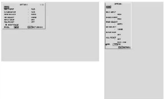
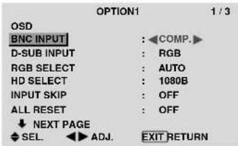
Setting the PC2/COMPONENT2 connectors
Select whether to set the PC2/COMPONENT2 to RGB, component or SCART1, 2.
Example: Set the BNC INPUT mode to "COMP."
On "BNC INPUT" of "OPTION1" menu, select "COMP".
text_image
OPTION1 1 / 3 OSD BNC INPUT : COMP.> D-SUB INPUT : RGB RGB SELECT : AUTO HD SELECT : 1080B INPUT SKIP : OFF ALL RESET : OFF ↓ NEXT PAGE SEL. ▶ ADJ. EXIT RETURNInformation
■ BNC INPUT Settings
RGB: Use the 5BNC terminals for HD, VD and RGB signals.
COMPONENT: Use the 3BNC terminals for component signals.
SCART1: Use the 4BNC terminals for RGB with composite sync. See page 6.
SCART2: Use the 3BNC terminals for RGB and the VIDEO1 terminal for composite sync. See page 6.
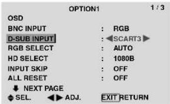
Setting the PC1 connector
Select one of the signals being transmitted to the PCI terminal.
Example: Set the D-SUB INPUT mode to "SCART3"
On "D-SUB INPUT" of "OPTION1" menu, select "SCART3".
text_image
OPTION1 1 / 3 OSD BNC INPUT : RGB D-SUB INPUT1 : SCART3 RGB SELECT : AUTO HD SELECT : 1080B INPUT SKIP : OFF ALL RESET : OFF ↓ NEXT PAGE SEL. ◀ ADJ. EXIT RETURNInformation
■ D-SUB INPUT Settings
RGB: Use the D-SUB terminal for RGB signals.
SCART3: Use the D-SUB terminal for RGB signal fed from SCART. See page 6.
Setting a computer image to the correct RGB select screen
With the computer image, select the RGB Select mode for a moving image such as (video) mode, wide mode or digital broadcast.
Example: Setting the "RGB SELECT" mode to "MOTION"
On “RGB SELECT” of “OPTION1” menu, select “MOTION”.

text_image
OPTION1 1 / 3 OSD BNC INPUT : RGB D-SUB INPUT : RGB RGB SELECT : ◀MOTION► HD SELECT 1024×768 INPUT SKIP : OFF ALL RESET : OFF ↓ NEXT PAGE SEL. ◀▶ ADJ. EXIT RETURNInformation
RGB SELECT modes
One of these 8 modes must be selected in order to display the following signals correctly.
AUTO: Select the suitable mode for the specifications of input signals as listed in the table “Computer input signals supported by this system” on page 29.
STILL: To display VESA standard signals. (Use this mode for a still image from a computer.)
MOTION: The video signal (from a scan converter) will be converted to RGB signals to make the picture more easily viewable. (Use this mode for a motion image from a computer.)
WIDE1: When an 852 dot×480 line signal with a horizontal frequency of 31.7kHz is input, the image may be compressed horizontally. To prevent this, set RGB SELECT to WIDE1.
WIDE2: When an 848 dot×480 line signal with a horizontal frequency of 31.0 kHz is input, the image may be compressed horizontally. To prevent this, set RGB SELECT to WIDE2.
WIDE3: When an 1920 dot × 1200 line signal with a horizontal frequency of 74.0 kHz is input, the image may be compressed horizontally. To prevent this, set RGB SELECT to WIDE3.
WIDE4: When an 1280 dot × 768 line signal with a horizontal frequency of 59.8 kHz or an 1680 dot × 1050 line signal with a horizontal frequency of 60 kHz is input, the image may be compressed horizontally. To prevent this, set RGB SELECT to WIDE4.
DTV: Set this mode when watching digital broadcasting (480P).
See page 29 for the details of the above settings.
Setting high definition images to the suitable screen size
Use this procedure to set whether the number of vertical lines of the input high definition image is 1035 or 1080.
Example: Setting the "HD SELECT" mode to "1035I"
On "HD SELECT" of "OPTION1" menu, select "1035I".

text_image
OPTION1 1 / 3 OSD BNC INPUT : RGB D-SUB INPUT : RGB RGB SELECT : AUTO HD SELECT : 1035T ▶ INPUT SKIP : OFF ALL RESET : OFF ↓ NEXT PAGE SEL. ▶ ADJ. EXIT RETURNInformation
■ HD SELECT modes
These 3 modes are not displayed in correct image automatically.
1080B: Standard digital broadcasts
1035l: Japanese "High Vision" signal format
1080A: Special Digital broadcasts (for example : DTC100)
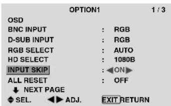
Setting the Input Skip
When this is ON, signals which are not present will be skipped over and only pictures whose signals are being transmitted will be displayed.
This setting is valid only for the INPUT/EXIT button on the unit.
Example: Set to "ON"
On "INPUT SKIP" of "OPTION1" menu, select "ON".
text_image
OPTION1 1 / 3 OSD BNC INPUT : RGB D-SUB INPUT : RGB RGB SELECT : AUTO HD SELECT : 1080B INPUT SKIP : ON ALL RESET : OFF ↓ NEXT PAGE SEL. ↓ ADJ. EXIT RETURNInformation
■ INPUT SKIP settings
OFF: Regardless of the presence of the signal, scan and display all signals.
ON: If no input signal is present, skip that signal.
* "SETTING NOW" will appear during the input search.
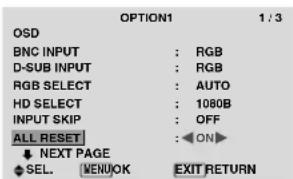
Resetting to the default values
Use these operations to restore all the settings (PICTURE, SOUND, SCREEN, OPTION1\~3, etc) to the factory default values.
Refer to page 12 for items to be reset.
On “ALL RESET” of “OPTION1” menu, select “ON”, then press the MENU/SET button.
text_image
OPTION1 1 / 3 OSD BNC INPUT : RGB D-SUB INPUT : RGB RGB SELECT : AUTO HD SELECT : 1080B INPUT SKIP : OFF ALL RESET : ON▶ NEXT PAGE SEL. MENUOK EXIT RETURN
text_image
ALL RESET SETTING NOWWhen the “SETTING NOW” screen disappears, then all the settings are restored to the default values.
Option2 Settings Menu
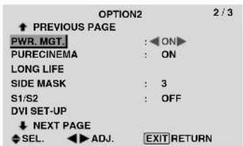
Setting the power management for computer images
This energy-saving (power management) function automatically reduces the monitor's power consumption if no operation is performed for a certain amount of time.
Example: Turning the power management function on Set "ADVANCED OSD" to "ON" in the main menu (1/2), then perform the following operations.
On "PWR. MGT." of "OPTION2" menu, select "ON".
text_image
OPTION2 2 / 3 ↑ PREVIOUS PAGE PWR. MGT. : ON PURECINEMA : ON LONG LIFE SIDE MASK : 3 S1/S2 : OFF DVI SET-UP ↓ NEXT PAGE SEL. ▶ ADJ. EXIT RETURNInformation
■ Power management function
* The power management function automatically reduces the monitor's power consumption if the computer's keyboard or mouse is not operated for a certain amount of time. This function can be used when using the monitor with a computer.
* If the computer's power is not turned on or if the computer and selector tuner are not properly connected, the system is set to the off state.
* For instructions on using the computer's power management function, refer to the computer's operating instructions.
■ Power management settings
ON: In this mode the power management function is turned on.
OFF: In this mode the power management function is turned off.
■ Power management function and STANDBY/ON indicator
The STANDBY/ON indicator indicates the status of the power management function. See below for indicator status and description.
STANDBY/ON indicator
| Power management mode | STANDBY/ON Indicator | Power management operating status | Description | Turning the picture back on |
| On | Green | Not activated. | Horizontal and vertical synchronizing signals are present from the computer. | Picture already on. |
| Off | Red | Activated | Horizontal and/or vertical synchronizing signals are not sent from the computer. | Operate the keyboard or mouse. The picture reappears. |
Setting the picture to suit the movie
The film image is automatically discriminated and projected in an image mode suited to the picture.
[NTSC, PAL, PAL60, 480I (60Hz), 525I (60Hz), 576I (50Hz), 625I (50Hz), 1035I (60Hz), 1080I (60Hz) only]
Example: Setting the "PURECINEMA" to "OFF"
Set "ADVANCED OSD" to "ON" in the main menu (1/2), then perform the following operations.
On "PURECINEMA" of "OPTION2" menu, select "OFF".
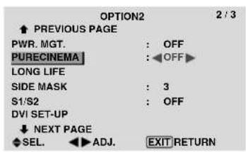
text_image
OPTION2 2 / 3 PREVIOUS PAGE PWR. MGT. : OFF PURECINEMA : OFF▶ LONG LIFE SIDE MASK : 3 S1/S2 : OFF DVI SET-UP NEXT PAGE SEL. ▶ ADJ. EXIT RETURNInformation
PURECINEMA
ON: Automatic discrimination of the image and projection in PURECINEMA.
OFF: PURECINEMA does not function.
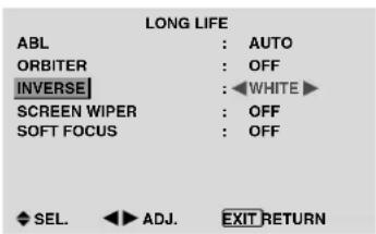
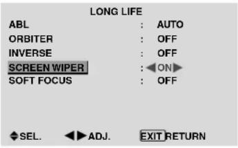
Reducing burn-in of the screen
The brightness of the screen, the position of the picture, positive/negative mode and screen wiper are adjusted to reduce burn-in of the screen.
Set "ADVANCED OSD" to "ON" in the main menu (1/2), then perform the following operations.
On "OPTION2" menu, select "LONG LIFE", then press the MENU/SET button.
The "LONG LIFE" screen appears.

text_image
LONG LIFE ABL : AUTO ORBITER : OFF INVERSE : OFF SCREEN WIPER : OFF SOFT FOCUS : OFF SEL. ADJ. EXIT RETURNABL (Auto Brightness Limiter)
Use this to activate the brightness limiter.
Example: Setting "ABL" to "LOCK1"
On "ABL" of "LONG LIFE" menu, select "LOCK1".

text_image
LONG LIFE ABL : ←LOCK1 ORBITER : OFF INVERSE : OFF SCREEN WIPER : OFF SOFT FOCUS : OFF SEL. ←ADJ. EXIT RETURNInformation
■ ABL settings
AUTO: The brightness of the screen is adjusted automatically to suit the picture quality.
LOCK1, 2, 3: Sets maximum brightness.
The brightness level decreases in the order of LOCK 1, 2, 3. LOCK 3 provides minimum brightness.
ORBITER
Use this to set the picture shift.
Example: Setting "ORBITER" to "AUTO1"
On "ORBITER" of "LONG LIFE" menu, select "AUTO1".

text_image
LONG LIFE ABL : AUTO ORBITER : AUTO1 INVERSE : OFF SCREEN WIPER : OFF SOFT FOCUS : OFF SEL. ADJ. EXIT RETURNInformation
■ ORBITER settings
OFF: Orbiter mode does not function.
This is the default setting when PC signal is input.
AUTO1: The picture moves around the screen intermittently, making the picture smaller. This is the default setting when a Video or a COMPONENT signal is input. Set to "OFF" when these signals are not used.
AUTO2: The picture moves around the screen intermittently, making the picture bigger.
MANUAL: User can adjust the orbiter function (Horizontal Dot, Vertical Line and Time) manually. See the following explanation.
* When a Video or a COMPONENT signal is input, the AUTO1 and 2 functions will affect only the moving picture and will not make the screen smaller or bigger.
Adjust the ORBITER function manually
Set the amount of shift and the time between movement.
Example: Setting so that the picture moves 2 dots horizontally and 4 lines vertically every 3 minutes.
On “ORBITER” of “LONG LIFE” menu, select “MANUAL”, then press the MENU/SET button.
THE "ORBITER" screen appears.
Adjust the items.
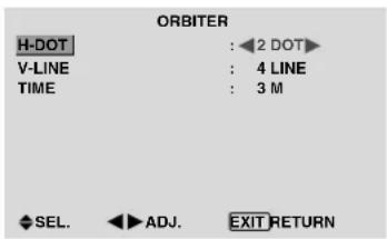
text_image
ORBITER H-DOT : 2 DOT V-LINE : 4 LINE TIME : 3 M SEL. ADJ. EXIT RETURNInformation
■ ORBITER Function settings
H-DOT: Moves from 1 to 20 dots in the horizontal direction.
V-LINE: Moves from 1 to 20 lines in the vertical direction.
TIME: Interval of 1\~5 minutes (1 horizontal dot or 1 vertical line per interval).
INVERSE
Use this to set the inverse mode or to display a white screen.
Example: Setting "INVERSE" to "WHITE"
On “INVERSE” of “LONG LIFE” menu, select “WHITE”.
text_image
LONG LIFE ABL : AUTO ORBITER : OFF INVERSE : ◀WHITE ► SCREEN WIPER : OFF SOFT FOCUS : OFF SEL. ◀ADJ. EXIT RETURNInformation
■ INVERSE Settings
ON: The picture is displayed alternately between positive image and negative image.
You can set the time by pressing the MENU/SET button while “ON” is set.
OFF: Inverse mode does not function.
WHITE: The entire screen turns white.
You can set the time by pressing the MENU/SET button while “ON” is set.
Setting the time for INVERSE/WHITE
Set a time duration.
Example: Setting to that the INVERSE mode starts in 2 hours and proceeds for one hour and a half.
On “INVERSE” of “LONG LIFE” menu, select “ON”, then press the MENU/SET button.
THE "INVERSE/WHITE" screen appears.
Adjust the times.
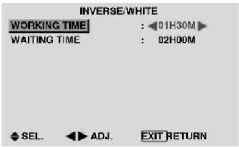
text_image
INVERSE/WHITE WORKING TIME : 01H30M WAITING TIME : 02H00M SEL. ADJ. EXIT RETURNInformation
■ Setting the time
WORKING TIME: Set the time duration for "INVERSE/WHITE".
When the WORKING TIME is set to “ON” the mode will stay on.
WAITING TIME: Set the standby time until the "INVERSE/WHITE" mode starts.
* The “WAITING TIME” can not be set when the “WORKING TIME” is ON.
* THE "WORKING TIME" and "WAITING TIME" can be set for up to 12 hours and 45 minutes in units of 3 minutes.
* Ending a WORKING TIME function, the monitor will be STAND BY.
[Example]
WORKING TIME: 01H30M
WAITING TIME: 02H00M
← ----------- 2 H ----*---- 1.5 H ----*---- Start INVERSE/WHITE Start STAND BY
■ To select "ON" for the "WORKING TIME"...
Set the hours of the working time to 0H and the minutes to 0M. "ON" will be displayed.
SCREEN WIPER
When this is set to ON, a white vertical bar moves repeatedly from the left and of the screen to the right end at a constant speed.
Example: Setting "SCREEN WIPER" to "ON"
On “SCREEN WIPER” of “LONG LIFE” menu, select “ON”.
text_image
LONG LIFE ABL : AUTO ORBITER : OFF INVERSE : OFF SCREEN WIPER : ON SOFT FOCUS : OFF SEL. ADJ. EXIT RETURNInformation
■ SCREEN WIPER
ON: The white vertical bar appears.
You can set the time by pressing the MENU/SET button while "ON" is set.
OFF: Screen wiper mode does not function.
Setting the time for SCREEN WIPER
Set a time duration and the speed.
Example: Setting so that the SCREEN WIPER mode starts in 30 minutes and proceeds for one and a half hours.
On “SCREEN WIPER” of “LONG LIFE” menu, select “ON”, then press the MENU/SET button.
THE "SCREEN WIPER" screen appears.
Adjust the times and speed.
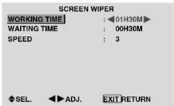
text_image
SCREEN WIPER WORKING TIME : 01H30M WAITING TIME : 00H30M SPEED : 3 SEL. ADJ. EXIT RETURNInformation
■ Setting the time
WORKING TIME: Set the time duration for “SCREEN WIPER”.
When the WORKING TIME is set to "ON" the mode will stay on.
WAITING TIME: Set the standby time until the "SCREEN WIPER" mode starts.
SPEED: Set the moving speed for the “SCREEN WIPER”. The speed decreases as the number increases.
* The “WAITING TIME” can not be set when the “WORKING TIME” is ON.
* THE “WORKING TIME” and “WAITING TIME” can be set for up to 12 hours and 45 minutes in units of 3 minutes.
■ To select "ON" for the "WORKING TIME"...
Set the hours of the working time to 0H and the minutes to 0M. “ON” will be displayed.
SOFT FOCUS
Reduces edges and softens the image.
Example: Setting "SOFT FOCUS" to "2"
On "SOFT FOCUS" of "LONG LIFE" menu, select "2".

text_image
LONG LIFE ABL : AUTO ORBITER : OFF INVERSE : OFF SCREEN WIPER : OFF SOFT FOCUS : ◀2▶ SEL. ◀ ADJ. EXIT RETURNInformation
■ SOFT FOCUS settings
OFF: Turns the SOFT FOCUS function off.
1, 2, 3, 4: Activates the SOFT FOCUS setting. The higher numbers create a softer image.
“SHARPNESS” can not be adjusted in the “PICTURE” menu.
Setting the gray level for the SIDE MASK
Use this procedure to set the gray level for the parts on the screen on which nothing is displayed when the screen is set to the 4:3 size or 14:9 size.
Example: Setting "SIDE MASK" to "5"
Set “ADVANCED OSD” to “ON” in the main menu (1/2), then perform the following operations.
On "SIDE MASK" of "OPTION2" menu, select "5".

text_image
OPTION2 2 / 3 ↑ PREVIOUS PAGE PWR. MGT. : OFF PURECINEMA : ON LONG LIFE SIDE MASK : ◀5► S1/S2 : OFF DVI SET-UP ↓ NEXT PAGE ◆ SEL. ◀▶ ADJ. EXIT RETURNInformation
■ SIDE MASK settings
This adjusts the brightness of the black (the gray level) for the sides of the screen.
The standard is 0 (black). The level can be adjusted from 0 to 15. The factory setting is 3 (dark gray).
Setting the screen size for S1/S2 video input
If the S-video signal contains screen size information, the image will be automatically adjusted to fit the screen when this S1/S2 is set to AUTO.
This feature is available only when an S-video signal is input via the VIDEO3 terminal.
Example: Setting "S1/S2" to "AUTO"
Set “ADVANCED OSD” to “ON” in the main menu (1/2), then perform the following operations.
On "S1/S2" of "OPTION2" menu, select "AUTO".

text_image
OPTION2 2 / 3 ↑ PREVIOUS PAGE PWR. MGT. : OFF PURECINEMA : ON LONG LIFE SIDE MASK : 3 S1/S2 : AUTO DVI SET-UP ↓ NEXT PAGE SEL. ▶ ADJ. EXIT RETURNInformation
■ S1/S2 settings
AUTO: Adjusts the screen size automatically according to the S1/S2 video signal.
OFF: Turns the S1/S2 function off.
Setting the signal and black level for DVI signal
Choose the signal for the DVI connector (PC or STB/DVD) and set the black level.
Example: Setting the "PLUG/PLAY" mode to "STB/DVD"
Set “ADVANCED OSD” to “ON” in the main menu (1/2), then perform the following operations.
On "OPTION2" menu, select "DVI SET-UP", then press the MENU/SET button.
The "DVI SET-UP" screen appears.
On “PLUG/PLAY” of “DVI SET-UP” menu, select “STB/DVD”.

text_image
DVI SET-UP PLUG/PLAY : STB/DVD BLACK LEVEL : HIGH SEL. ADJ. EXIT RETURNInformation
■ PLUG/PLAY settings
PC: When connected to the PC signal.
BLACK LEVEL is set to "LOW" automatically.
STB/DVD: When connected to the SET TOP BOX, DVD etc.
BLACK LEVEL is set to "HIGH" automatically.
LOW: When connected to the PC signal.
HIGH: When connected to the SET TOP BOX, DVD etc.
Change “HIGH” into “LOW” if the black level appears gray.
Option3 Settings Menu Using the timer
This function sets the monitor to turn ON/OFF automatically at a set time.
Set “ADVANCED OSD” to “ON” in the main menu (1/2), then perform the following operations.
On “OPTION3” menu, select “TIMER”, then press the MENU/SET button.
The "TIMER" screen appears.
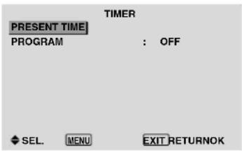
text_image
TIMER PRESENT TIME PROGRAM : OFF SEL. MENU EXIT RETURNOKPRESENT TIME
This sets the day of the week and present time.
Example: Setting "WEDNESDAY", "22:05"
On "TIMER" menu, select "PRESENT TIME", then press the MENU/SET button.
The "PRESENT TIME" screen appears.
Adjust the items.
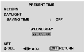
text_image
PRESENT TIME RETURN DAYLIGHT SAVING TIME : OFF WEDNESDAY 22:05:00 SET SEL. ADJ. EXIT RETURNSelect "SET", then press the MENU/SET button.
The adjustments are stored and return to the TIMER menu.
* If you press the EXIT button instead of the MENU/SET button, the settings can not be made.

text_image
PRESENT TIME RETURN DAYLIGHT SAVING TIME : OFF WEDNESDAY 22:05:00 SET SEL. MENU OK EXIT RETURNInformation
■ PRESENT TIME settings
DAYLIGHT SAVING TIME: Use to set DAYLIGHT SAVING TIME.
ON: The present time + 1 hour.
OFF: Cancelled
Day: Set the day of the week (e.g. Sunday).
Hour: Set the hour in the 24-hour format (range 00 to 23).
Minutes: Set the minutes (range 00 to 59).
PROGRAM TIMER
This sets the day and time at which the power will be switched ON/OFF as well as the input mode.
Example: Setting so that the power will be switched on at 8:30 A.M., Monday, displaying PC2 source, and switched off at 10:30 A.M.
On "PROGRAM" of "TIMER" menu, select "ON", then press the MENU/SET button.
The "PROGRAM TIMER" screen appears.
Adjust the items.
Each mode switches each time the ZOOM +/- button is pressed.
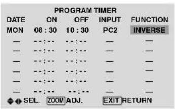
text_image
PROGRAM TIMER DATE ON OFF INPUT FUNCTION MON 08:30 10:30 PC2 INVERSE - - - - - - - - - - - - - - - - - - - - - - - - - - - - - - - - SEL. ZOOM ADJ. EXIT RETURNInformation
■ PROGRAM TIMER settings
DATE: Set the day of the week (e.g. Sunday).
ON (hour, minutes): Set the time at which the power will be turned on in the 24-hour format.
OFF (hour, minutes): Set the time at which the power will be turned off in the 24-hour format.
INPUT: Set the input mode that will be displayed when the timer is on.
FUNCTION: Set the LONG LIFE function.
■ To reset the program
Align the cursor with the DATE field that you wish to reset, then press the CLEAR button.
■ To reset the data
Align the cursor with the field (ON/OFF/INPUT/FUNCTION) that you wish to reset, then press the CLEAR button.
■ Special characters in the PROGRAM TIMER screen
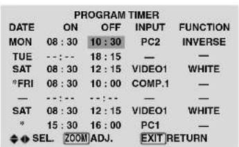
text_image
PROGRAM TIMER DATE ON OFF INPUT FUNCTION MON 08:30 10:30 PC2 INVERSE TUE --:-- 18:15 — — SAT 08:30 12:15 VIDEO1 WHITE *FRI 08:30 10:00 COMP.1 — — --:-- --:-- — SAT 08:30 12:15 VIDEO1 WHITE * 15:30 16:00 PC1 — SEL ZOOM ADJ. EXIT RETURN• An asterisk “*” in the DATE field
An asterisk “*” means “every”. For example, “*FRI” means every Friday and “*” means everyday.
- A hyphen “-” in the ON field or OFF field
If any hyphen remains in the ON field or OFF field, the FUNCTION can not be set.
- A hyphen “-” in the FUNCTION field
A hyphen “-” means last mode (the mode that was last selected at the time the power was switched off).
Setting the power on mode
This function sets the input mode at the time the power is switched on.
Example: Setting "VIDEO2"
Set "ADVANCED OSD" to "ON" in the main menu (1/2), then perform the following operations.
On "PWR. ON MODE" of "OPTION3" menu, select "VIDEO2".
The available inputs depend on the setting of input.

text_image
OPTION3 3 / 3 ↑ PREVIOUS PAGE TIMER PWR. ON MODE : ◀ VIDEO2 KEY LOCK : OFF IR REMOTE : ON LOOP OUT : OFF ID NUMBER : ALL VIDEO WALL SEL. ▶ ADJ. EXIT RETURNInformation
■ PWR. ON MODE settings
LAST: Last mode (the input that was last selected at the time the power was switched off).
VIDEO1, 2, 3: VIDEO input mode.
PC1, 2, 3: PC input mode.
COMPONENT1, 2: COMPONENT input mode.
Follow the procedure used for PROGRAM TIMER.
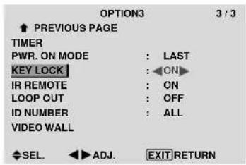
Enabling/disabling the front panel controls
This function enables/disables the front panel controls.
Example: Setting "ON"
Set "ADVANCED OSD" to "ON" in the main menu (1/2), then perform the following operations.
On "KEY LOCK" of "OPTION3" menu, select "ON", then press the MENU/SET button.
text_image
OPTION3 3 / 3 ↑ PREVIOUS PAGE TIMER PWR. ON MODE : LAST KEY LOCK : ON IR REMOTE : ON LOOP OUT : OFF ID NUMBER : ALL VIDEO WALL SEL. ADJ. EXIT RETURNInformation
■ KEY LOCK settings
ON: Disables the buttons on the front panel.
OFF: Enables the buttons on the front panel.
* Even when the KEY LOCK is set, the POWER switch will not be locked.
* This becomes effective when the OSD goes out.
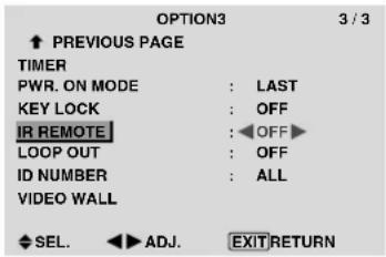
Enabling/disabling remote control wireless transmission
This function enables/disables remote control wireless transmission.
Example: Setting "OFF"
Set “ADVANCED OSD” to “ON” in the main menu (1/2), then perform the following operations.
On “IR REMOTE” of “OPTION3” menu, select “OFF”, then press the MENU/SET button.
text_image
OPTION3 3 / 3 ↑ PREVIOUS PAGE TIMER PWR. ON MODE : LAST KEY LOCK : OFF IR REMOTE : OFF LOOP OUT : OFF ID NUMBER : ALL VIDEO WALL SEL. ADJ. EXITRETURNInformation
■ IR REMOTE settings
ON: Enables remote control wireless transmission. OFF: Disables remote control wireless transmission. Set “OFF” to avoid unwanted control from other remote controls.
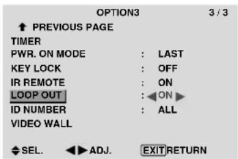
Loop Out setting
When this feature is set to ON, the received signal will be looped out.
Example: Setting "ON"
Set “ADVANCED OSD” to “ON” in the main menu (1/2), then perform the following operations.
On "LOOP OUT" of "OPTION3" menu, select "ON".
text_image
OPTION3 3 / 3 ↑ PREVIOUS PAGE TIMER PWR. ON MODE : LAST KEY LOCK : OFF IR REMOTE : ON LOOP OUT : ON ▶ ID NUMBER : ALL VIDEO WALL SEL. ▶ ADJ. EXIT RETURNInformation
■ LOOP OUT settings
ON: The received signal will be looped out via PC1 terminal or VIDEO1 terminal.
OFF: The received signal will not loop out.
* Even if LOOP OUT is ON, signals won't be sent out if POWER is being turned off.
■ To connect another display...
See page 3.
■ If the PC1 signal is present at the time the power switched on...
The PC1 input will be displayed regardless of the setting of LOOP OUT.
ID number setting
When using more than one of these displays, this function sets ID numbers so that operation of the remote control does not cause multiple monitors to operate at the same time.
Example: Setting "2"
Set “ADVANCED OSD” to “ON” in the main menu (1/2), then perform the following operations.
On "TD NUMBER" of "OPTION3" menu, select "2".

text_image
OPTION3 3 / 3 ↑ PREVIOUS PAGE TIMER PWR. ON MODE : LAST KEY LOCK : OFF IR REMOTE : ON LOOP OUT : OFF ID NUMBER : ◀2▶ VIDEO WALL SEL. ▶ ADJ. EXIT RETURN* To reset back to ALL
Press the CLEAR button.
Information
ID NUMBER settings
ALL: ID NUMBER will not be set.
1 to 256: ID NUMBER will be set.
■ When the ID NUMBER have been set
You can also set ID NUMBER for each remote control to operate the plasma display individually. To do so, see below.
To set the ID number for the remote control
Example: Setting "2"
Press the ID NO. SET button on the remote control.
The "ID NO. SET" screen appears.
On "ID NUMBER" of "ID NO. SET" menu, select "2".

text_image
ID NO.SET POSITION : 1 ID NUMBER : ◀2 ◀▶ ADJ. EXIT RETURN* To reset back to ALL
Press the CLEAR button.
Video Wall setting
Use this feature to configure a 4-25 video wall.
Set “ADVANCED OSD” to “ON” in the main menu (1/2), then perform the following operations.
On "OPTION3" menu, select "VIDEO WALL", then press the MENU/SET button.
The "VIDEO WALL" screen appears.
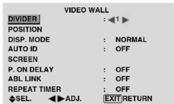
text_image
VIDEO WALL DIVIDER : ◀1 ▶ POSITION DISP. MODE : NORMAL AUTO ID : OFF SCREEN P. ON DELAY : OFF ABL LINK : OFF REPEAT TIMER : OFF SEL. ADJ. EXIT RETURNNote: A contingency method of shutting off the electric power should be used in cases of emergency during video wall setup.
DIVIDER
Set the 4-25 video wall.
Example: Setting "4"
On "DIVIDER" of "VIDEO WALL" menu, select "4".
| VIDEO WALL | |
| DIVIDER | : 4 |
| POSITION | |
| DISP. MODE | : NORMAL |
| AUTO ID | : OFF |
| SCREEN | |
| P. ON DELAY | : OFF |
| ABL LINK | : OFF |
| REPEAT TIMER | : OFF |
| SEL. ADJ. EXIT RETURN | |
Information
■ DIVIDER settings
OFF, 1:1 Screen (Matrix display function does not work)
4: 4 Screens (2×2 video wall)
9: 9 Screens (3×3 video wall)
16: 16 Screens (4×4 video wall)
25: 25 Screens (5×5 video wall)
* When you select 4-25, set the VIDEO WALL POSITION.
VIDEO WALL POSITION
Set the position of each display.
Example: Setting "4"
On "VIDEO WALL" menu, select "POSITION", then press the MENU/SET button.
The "VIDEO WALL POSITION" screen appears.
Select "NO. 4" of "POSITION NO.".

text_image
VIDEO WALL POSITION POSITION NO. 4 ADJ. EXIT RETURNInformation
■ VIDEO WALL POSITION settings
1 Screen: There is no need to set POSITION.
4 Screens 9 Screens
| NO. 1 | NO. 2 |
| NO. 4 | NO. 3 |
| NO. 7 | NO. 8 | NO. 9 |
| NO. 10 | NO. 11 | NO. 12 |
| NO. 13 | NO. 14 | NO. 15 |
16 Screens 25 Screens
| NO. 16 | NO. 17 | NO. 18 | NO. 19 |
| NO. 20 | NO. 21 | NO. 22 | NO. 23 |
| NO. 24 | NO. 25 | NO. 26 | NO. 27 |
| NO. 28 | NO. 29 | NO. 30 | NO. 31 |
| NO. 32 | NO. 33 | NO. 34 | NO. 35 | NO. 36 |
| NO. 37 | NO. 38 | NO. 39 | NO. 40 | NO. 41 |
| NO. 42 | NO. 43 | NO. 44 | NO. 45 | NO. 46 |
| NO. 47 | NO. 48 | NO. 49 | NO. 50 | NO. 51 |
| NO. 52 | NO. 53 | NO. 54 | NO. 55 | NO. 56 |
DISP. MODE
Select the screen mode from between two options (NORMAL, ADJUST).
Example: Setting "ADJUST"
On “DISP. MODE” of “VIDEO WALL” menu, select “ADJUST”.
| VIDEO WALL | |
| DIVIDER | : 1 |
| POSITION | |
| DISP. MODE | :ADJUST |
| AUTO ID | : OFF |
| SCREEN | |
| P. ON DELAY | : OFF |
| ABL LINK | : OFF |
| REPEAT TIMER | : OFF |
| SEL. ADJ. EXIT RETURN | |
Information
■ DISP. MODE settings
NORMAL: Combines enlarged screens and creates multiple screens.
ADJUST: Corrects misalignment of combined screen portions and creates multiple screens
AUTO ID
This feature automatically sets the ID numbers of multiple displays connected to each other.
Example: Setting "ON"
Set the ID number for the No. 1 display on ID NUMBER menu.
On “AUTO ID” of “VIDEO WALL” menu, select “ON”, then press the MENU/SET button.

flowchart
graph TD
    A["AUTO ID"] --> B["1 ▶ 2"]
    B --> C["4 ◀ 3"]
    D["ON"] --> E["1 ▶ 2 ▶ 3"]
    E --> F["8 ▶ 9 ▶ 4"]
    F --> G["7 ◀ 6 ◀ 5"]
    H["EXIT"] --> I["ADJ."]
    I --> J["EXIT RETURN"]
Information
■ AUTO ID settings
ON: Enables Auto ID function. In the case shown below, display 1 will be set as ID 1, display 2 as ID2, etc.
This can be set only when a 2 × 2 or 3 × 3 video wall is selected.
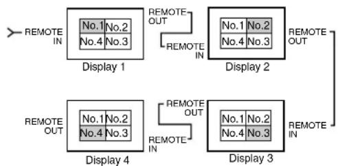
flowchart
graph TD
    A["Display 1"] -->|REMOTE OUT| B["Display 2"]
    B -->|REMOTE OUT| C["Display 3"]
    C -->|REMOTE OUT| D["Display 4"]
    D -->|REMOTE OUT| A
    style A fill:#f9f,stroke:#333
    style B fill:#f9f,stroke:#333
    style C fill:#f9f,stroke:#333
    style D fill:#f9f,stroke:#333
OFF: Disables Auto ID function.
SCREEN
The position of the image can be adjusted and flickering of the image can be corrected.
Example: Adjusting the vertical position
On "VIDEO WALL" menu, select "SCREEN", then press the MENU/SET button.
The "SCREEN" screen appears.
On "V.POSITION" of "SCREEN" menu, adjust the position.

text_image
SCREEN SCREEN SIZE : 4 : 3 V.POSITION H.POSITION V.SIZE H.SIZE AUTO PICTURE : OFF PHASE CLOCK SEL. ADJ. EXIT RETURN V.POSITION +64Information
■ SCREEN settings
These are the same functions as the SCREEN menu on page 16.
P. ON DELAY (Power on delay)
Use this function to activate power-on delay.
Turn on the AUTO ID before the following operations.
Example: Setting "ON"
On "P. ON DELAY" of "VIDEO WALL" menu, select "ON".
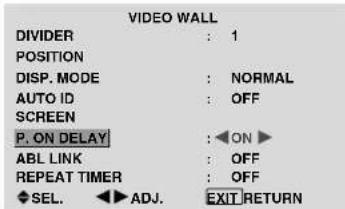
text_image
VIDEO WALL DIVIDER : 1 POSITION DISP. MODE : NORMAL AUTO ID : OFF SCREEN P. ON DELAY : ON ▶ ABL LINK : OFF REPEAT TIMER : OFF SEL. ▶ ADJ. EXIT RETURNInformation
■ P. ON DELAY settings
ON: Turns on the main power of each display after a delay time.
OFF: Turns on the main power of all displays at the same time.
(Only for 16 and 25 screens)
MODE1: Turns on the main power of each display delayed.
MODE2: Turns on the main power of each display more delayed.
* Once this function has been set to "ON", the POWER ON/OFF button on the remote control does not function except for the No.1 monitor.
By pressing the POWER ON button on the remote control the No.1 monitor will turn on and the others will be turned on one by one automatically.
* From the second monitor onward, neither the POWER button on the unit nor the POWER ON button on the remote control works. However, by pressing and holding the POWER ON button for more than 3 seconds, the monitor will be turned on.
ABL LINK
Use this function to set a uniform brightness for each display.
Turn on the AUTO ID and set the DIVIDER (at 1, 4 or 9) before the following operations.
Example: Setting "ON"
On "ABL LINK" of "VIDEO WALL" menu, select "ON", then press the MENU/SET button.
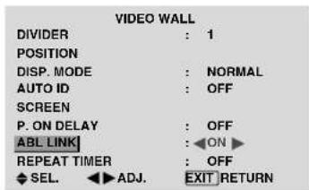
text_image
VIDEO WALL DIVIDER : 1 POSITION DISP. MODE : NORMAL AUTO ID : OFF SCREEN P. ON DELAY : OFF ABL LINK : ON ▶ REPEAT TIMER : OFF SEL. ADJ. EXIT RETURNInformation
■ ABL LINK settings
ON: Sets a uniform brightness for each screen in a video wall. This can be set only when a 2×2 or 3×3 video wall is selected.
OFF: Sets the individual screen brightness for each screen in a video wall.
* When this function is set "ON", connect your plasma displays with the remote cable (optional) in the order of the position numbers for the 2×2 video wall. See the drawing below.
* If there are changes in the DIVIDER or POSITION, the ABL LINK will automatically turn OFF.

flowchart
graph TD
    A["Display 1"] -->|REMOTE IN| B["Display 2"]
    A -->|REMOTE OUT| C["Display 3"]
    A -->|REMOTE IN| D["Display 4"]
    A -->|REMOTE OUT| E["Display 4"]
    A -->|REMOTE IN| F["Display 4"]
    A -->|REMOTE OUT| G["Display 4"]
    A -->|REMOTE IN| H["Display 4"]
    A -->|REMOTE OUT| I["Display 4"]
    A -->|REMOTE IN| J["Display 4"]
    A -->|REMOTE OUT| K["Display 4"]
    A -->|REMOTE IN| L["Display 4"]
    A -->|REMOTE OUT| M["Display 4"]
* With the 3×3 video wall, connect the final display to the first display the same way as with 2×2 video wall.
Note: The remote control can be operated unless the IR REMOTE is set to "OFF".
REPEAT TIMER
Use this to set two timers. Each timer can use the DIVIDER, SOURCE and WORK TIME functions.
Turn on the AUTO ID and set the DIVIDER (at 1, 4 or 9) before the following operations.
Example:
TIMER1...VIDEO1 will be displayed for 3 minutes.
TIMER2...PC1 will be displayed for 6 minutes in a 2×2 video wall.
On “REPEAT TIMER” of “VIDEO WALL” menu, select “ON”, then press the MENU/SET button.
The "REPEAT TIMER" screen appears.
Adjust the items.
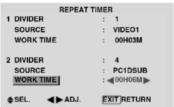
text_image
REPEAT TIMER 1 DIVIDER : 1 SOURCE : VIDEO1 WORK TIME : 00H03M 2 DIVIDER : 4 SOURCE : PC1DSUB WORK TIME : 00H06M SEL. ADJ. EXIT RETURNInformation
■ REPEAT TIMER settings
DIVIDER: Divide the screen into 1, 4 or 9 sections.
SOURCE: Set the input mode to be displayed.
WORK TIME: Can be set to up to 4 hours 15 minutes in units of 1 minute.
If you set both timers, Timer 1 and Timer 2 run consecutively.
In the case of the Video wall, timer No.1 can be used to control all the displays simultaneously.
* This becomes effective when the OSD goes out.
Advanced OSD Settings Menu Setting the menu mode
This allows you to access full menu items.
When P. ON DELAY or ABL LINK is ON, this won't be turned OFF.
Example: Setting "ON"
On "ADVANCED OSD" of "MAIN MENU", select "ON".
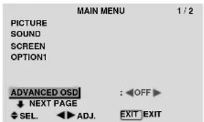
text_image
MAIN MENU 1 / 2 PICTURE SOUND SCREEN OPTION1 ADVANCED OSDI : OFF NEXT PAGE SEL. ADJ. EXIT EXIT
text_image
MAIN MENU 1 / 2 PICTURE SOUND SCREEN OPTION1 OPTION2 OPTION3 ADVANCED OSD : ON ▶ ↓ NEXT PAGE SEL. ADJ. EXIT EXITInformation
■ ADVANCED OSD settings
ON: All of the main menu items are available for advanced users.
OFF: Some of the main menu items are not available (e.g. OPTION2 and OPTION3).
Color System Settings Menu Setting the video signal format
Use these operations to set the color systems of composite video signals or Y/C input signals.
Example: Setting the color system to "3.58 NTSC"
On the MAIN MENU, select "COLOR SYSTEM", then press the MENU/SET button.
The "COLOR SYSTEM" screen appears.
On "COLOR SYSTEM", select "3.58NTSC".

text_image
COLOR SYSTEM COLOR SYSTEM : 3.58NTSC ADJ. EXIT RETURNInformation
■ Video signal formats
Different countries use different formats for video signals. Set to the color system used in your current country.
AUTO: The color systems are automatically identified and the format is set accordingly.
PAL: This is the standard format used mainly in the United Kingdom and Germany.
SECAM: This is the standard format used mainly in France and Russia.
4.43 NTSC, PAL60: This format is used for videos in countries using PAL and SECAM video signals.
3.58 NTSC: This is the standard format used mainly in the United States and Japan.
PAL-M: This is the standard format used mainly in Brazil.
PAL-N: This is the standard format used mainly in Argentina.
Source Information Menu
Checking the frequencies, polarities of input signals, and resolution
Use this function to check the frequencies and polarities of the signals currently being input from a computer, etc. On “MAIN MENU”, select “SOURCE INFORMATION”, then press the MENU/SET button.
The "SOURCE INFORMATION" is displayed.

text_image
SOURCE INFORMATION H. FREQUENCY : 48.4kHz V. FREQUENCY : 60.0Hz H. POLARITY : NEG. V. POLARITY : NEG. MEMORY : 24 RESOLUTION : 1024×768 EXIT RETURNPC: MEMORY will be displayed.
Others: MODE will be displayed.
| Pin No. | Signal (Analog) |
| 1 | Red |
| 2 | Green or sync-on-green |
| 3 | Blue |
| 4 | No connection |
| 5 | Ground |
| 6 | Red ground |
| 7 | Green ground |
| 8 | Blue ground |
| 9 | No connection |
| 10 | Sync signal ground |
| 11 | No connection |
| 12 | Bi-directional DATA (SDA) |
| 13 | Horizontal sync or Composite sync |
| 14 | Vertical sync |
| 15 | Data clock |
DVI-D 24-pin connector (Digital)
The unit is equipped with a type of connector commonly used for digital.
(This cannot be used for an analog input.)
(TMDS can be used for one link only.)
PC 3
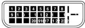
| Pin No. | Signal (Digital) |
| 1 | T.M.D.S Data 2 - |
| 2 | T.M.D.S Data 2 + |
| 3 | T.M.D.S Data 2 Shield |
| 4 | No connection |
| 5 | No connection |
| 6 | DDC Clock |
| 7 | DDC Data |
| 8 | No connection |
| 9 | T.M.D.S Data 1 - |
| 10 | T.M.D.S Data 1 + |
| 11 | T.M.D.S Data 1 Shield |
| 12 | No connection |
| 13 | No connection |
| 14 | +5V Power |
| 15 | Ground |
| 16 | Hot Plug Detect |
| 17 | T.M.D.S Data 0 - |
| 18 | T.M.D.S Data 0 + |
| 19 | T.M.D.S Data 0 Shield |
| 20 | No connection |
| 21 | No connection |
| 22 | T.M.D.S Clock Shield |
| 23 | T.M.D.S Clock + |
| 24 | T.M.D.S Clock - |
Table of Signals Supported
Supported resolution
- When the screen mode is NORMAL, each signal is converted to a 640 dots × 480 lines signal. (Except for *2, *4)
- When the screen mode is FULL, each signal is converted to a 853 dots × 480 lines signal. (Except for *)
Computer input signals supported by this system
| Model | Dots × lines | Vertical frequency (Hz) | Horizontal frequency (kHz) | Sync Polarity | Presence | Screen mode | RGB select*5 | DVI | Memory | |||
| Horizontal | Vertical | Horizontal | Vertical | NORMAL (4:3) | FULL (16:9) | |||||||
| Signal Type | ||||||||||||
| 640×400 | 70.1 | 31.5 | NEG | NEG | YES | YES | YES^2*3 | YES | -- | NO | 4 | |
| IBM PC/AT compatible computers*8 | 640×480 | 59.9 | 31.5 | NEG | NEG | YES | YES | YES^*3 | YES | STILL | YES | 5 |
| 72.8 | 37.9 | NEG | NEG | YES | YES | YES^*3 | YES | -- | YES | 7 | ||
| 75.0 | 37.5 | NEG | NEG | YES | YES | YES^*3 | YES | STILL | YES | 8 | ||
| 85.0 | 43.3 | NEG | NEG | YES | YES | YES^*3 | YES | -- | YES | 9 | ||
| 100.4 | 51.1 | NEG | NEG | YES | YES | YES^*3 | YES | -- | YES | 41 | ||
| 120.4 | 61.3 | NEG | NEG | YES | YES | YES^*3 | YES | -- | YES | 42 | ||
| 848×480 | 60.0 | 31.0 | POS | POS | YES | YES | -- | YES^*3 | WIDE2 | YES | 19 | |
| 852×480^*1 | 60.0 | 31.7 | NEG | NEG | YES | YES | -- | YES^*3 | WIDE1 | YES | 17 | |
| 800×600 | 56.3 | 35.2 | POS | POS | YES | YES | YES | YES | STILL | YES | 11 | |
| 60.3 | 37.9 | POS | POS | YES | YES | YES | YES | STILL | YES | 12 | ||
| 72.2 | 48.1 | POS | POS | YES | YES | YES | YES | -- | YES | 13 | ||
| 75.0 | 46.9 | POS | POS | YES | YES | YES | YES | -- | YES | 14 | ||
| 85.1 | 53.7 | POS | POS | YES | YES | YES | YES | -- | YES | 15 | ||
| 99.8 | 63.0 | POS | POS | YES | YES | YES | YES | -- | YES | 43 | ||
| 120.0 | 75.7 | POS | POS | YES | YES | YES | YES | -- | YES | 44 | ||
| 1024×768 | 60.0 | 48.4 | NEG | NEG | YES | YES | YES | YES | STILL | YES | 24 | |
| 70.1 | 56.5 | NEG | NEG | YES | YES | YES | YES | -- | YES | 25 | ||
| 75.0 | 60.0 | POS | POS | YES | YES | YES | YES | STILL | YES | 26 | ||
| 85.0 | 68.7 | POS | POS | YES | YES | YES | YES | -- | YES | 27 | ||
| 100.6 | 80.5 | NEG | NEG | YES | YES | YES | YES | -- | YES | 45 | ||
| 1152×864 | 75.0 | 67.5 | POS | POS | YES | YES | YES | YES | STILL | YES | 51 | |
| 1280×768 | 56.2 | 45.1 | POS | POS | YES | YES | -- | YES | WIDE1 | NO | 52 | |
| 59.8 | 48.0 | POS | NEG | YES | YES | -- | YES | WIDE3 | YES | 80 | ||
| 1280×768^*9 | 69.8 | 56.0 | NEG | POS | YES | YES | -- | YES | WIDE1 | YES | 66 | |
| 1280×800^*9 | 60.0 | 49.7 | NEG | NEG | YES | YES | -- | YES | WIDE1 | YES | 21 | |
| 1280×854^*9 | 60.0 | 53.1 | NEG | NEG | YES | YES | -- | YES | WIDE2 | YES | 37 | |
| 1360×765 | 60.0 | 47.7 | POS | POS | YES | YES | -- | YES | WIDE1 | NO | 22 | |
| 1360×768 | 60.0 | 47.7 | POS | POS | YES | YES | -- | YES | WIDE1 | YES | 22 | |
| 1376×768 | 59.9 | 48.3 | NEG | POS | YES | YES | -- | YES | WIDE2 | YES | 53 | |
| 1280×1024 | 60.0 | 64.0 | POS | POS | YES | YES | YES^*4 | YES | STILL | YES | 29 | |
| 75.0 | 80.0 | POS | POS | YES | YES | YES^*4 | YES | -- | YES | 30 | ||
| 85.0 | 91.1 | POS | POS | YES | YES | YES^*4 | YES | -- | YES | 40 | ||
| 100.1 | 108.5 | POS | POS | YES | YES | YES^*4 | YES | -- | NO | 47 | ||
| 1680×1050^*9 | 60.0 | 65.3 | NEG | NEG | YES | YES | -- | YES | WIDE4 | YES | 38 | |
| 1600×1200 | 60.0 | 75.0 | POS | POS | YES | YES | YES | YES | -- | YES | 54 | |
| 65.0 | 81.3 | POS | POS | YES | YES | YES | YES | -- | NO | 55 | ||
| 70.0 | 87.5 | POS | POS | YES | YES | YES | YES | -- | NO | 56 | ||
| 75.0 | 93.8 | POS | POS | YES | YES | YES | YES | -- | NO | 57 | ||
| 85.0 | 106.3 | POS | POS | YES | YES | YES | YES | -- | NO | 58 | ||
| 1920×1200^*9 | 60.0 | 74.6 | NEG | NEG | YES | YES | -- | YES | WIDE2 | -- | 81 | |
| 1920×1200RB^*9 | 60.0 | 74.0 | NEG | NEG | YES | YES | -- | YES | WIDE3 | YES | 88 | |
| Apple Macintosh*5, *8 | 640×480 | 66.7 | 35.0 | Sync on G | Sync on G | -- | -- | YES^*3 | YES | -- | NO | 6 |
| 832×624 | 74.6 | 49.7 | Sync on G | Sync on G | -- | -- | YES | YES | -- | NO | 16 | |
| 1024×768 | 74.9 | 60.2 | Sync on G | Sync on G | -- | -- | YES | YES | WIDE1 | NO | 28 | |
| 1152×870 | 75.1 | 68.7 | Sync on G | Sync on G | -- | -- | YES | YES | WIDE1 | NO | 39 | |
| 1440×900^*9 | 60.0 | 56.0 | NEG | NEG | YES | YES | -- | YES | -- | YES | 89 | |
| Work Station (EWS4800)*8 | 1280×1024 | 60.0 | 64.6 | NEG | NEG | YES | YES | YES^*4 | YES | -- | YES | 29 |
| 71.2 | 75.1 | NEG | NEG | YES | YES | YES^*4 | YES | -- | YES | 48 | ||
| Work Station (HP)*8 | 1280×1024 | 72.0 | 78.1 | -- | -- | -- | -- | YES^*4 | YES | -- | YES | 59 |
| Work Station (SUN)*8 | 1152×900 | 66.0 | 61.8 | C Sync | C Sync | -- | -- | YES | YES | -- | YES | 60 |
| 76.0 | 71.7 | C Sync | C Sync | -- | -- | YES | YES | -- | YES | 61 | ||
| 1280×1024 | 76.1 | 81.1 | C Sync | C Sync | -- | -- | YES^*4 | YES | -- | YES | 30 | |
| Work Station (SGI) | 1024×768 | 60.0 | 49.7 | -- | -- | -- | -- | YES | YES | -- | YES | 62 |
| 1280×1024 | 60.0 | 63.9 | -- | -- | -- | -- | YES^*4 | YES | -- | YES | 29 | |
| IDC-3000G | ||||||||||||
| PAL625P | 768×576 | 50.0 | 31.4 | NEG | NEG | YES | YES | YES^*7 | -- | NO | 31 | |
| NTSC525P | 640×480 | 59.9 | 31.5 | NEG | NEG | YES | YES | YES^*7 | MOTION | NO | 32 | |
*1 Only when using a graphic accelerator board that is capable of displaying 852×480.
*2 Display only 400 lines with the screen center of the vertical orientation located at the center.
*3 The picture is displayed in the original resolution. The picture will be compressed for other signals.
*4 Aspect ratio is 5:4. This signal is converted to a 600 dots × 480 lines signal.
*5 Normally the RGB select mode suite for the input signals is set automatically. If the picture is not displayed properly, set the RGB mode prepared for the input signals listed in the table above.
*6 To connect the monitor to Macintosh computer, use the monitor adapter (D-Sub 15-pin) to your computer's video port.
*7 Other screen modes (ZOOM and WIDE) are available as well.
*8 When viewing a moving picture at a vertical frequency greater than 65Hz, the picture may sometimes be unstable (jumpy). If this occurs, please set the refresh rate of the external equipment to 60Hz.
To view 480I@60Hz (480 interlaced lines, 60Hz refresh rate) or 576I@50Hz (576 interlaced lines, 50Hz refresh rate) when sync polarity is “Sync on Green”, set “RGB SELECT” to “MOTION”.
*9 CVT standard compliant.
NOTE:
- While the input signals comply with the resolution listed in the table above, you may have to adjust the position and size of the picture or the fine picture because of errors in synchronization of your computer.
- This monitor has a resolution of 853 dots × 480 lines. It is recommended that the input signal be VGA, wide VGA or equivalent.
- With digital input some signals are not accepted.
- The sync may be disturbed when a nonstandard signal other than the aforementioned is input.
- If you are connecting a composite sync signal, use the HD terminal.
What is HDCP/HDCP technology?
HDCP is an acronym for High-bandwidth Digital Content Protection. High bandwidth Digital Content Protection (HDCP) is a system for preventing illegal copying of video data sent over a Digital Visual Interface (DVI).
If you are unable to view material via the DVI input, this does not necessarily mean the PDP is not functioning properly. With the implementation of HDCP, there may be cases in which certain content is protected with HDCP and might not be displayed due to the decision/intention of the HDCP community (Digital Content Protection, LLC).
* "IBM PC/AT" and "VGA" are registered trademarks of International Business Machines, Inc. of the United States.
* "Apple Macintosh" is a registered trademark of Apple Computer, Inc. of the United States.
If the picture quality is poor or there is some other problem, check the adjustments, operations, etc., before requesting service.
| Symptom | Checks | Remedy |
| The unit emits a crackling sound. | Are the image and sound normal? | If there are no abnormalities in the image and sound, the noise is caused by the cabinet reacting to changes in temperature. This will not affect performance. |
| Picture is disturbed.Sound is noisy.Remote control operates erroneously. | Is a connected component set directly in front or at the side of the display? | Leave some space between the display and the connected components. |
| The remote control does not work. | Are the remote control's batteries worn out? | Replace both batteries with new ones. |
| Is IR REMOTE set to ON? | Set IR REMOTE OFF on OPTION3 menu. | |
| Has an ID number been set for the main unit? | Set an ID number with the ID NO. SET button, or set the ID number to ALL. | |
| Monitor's power does not turn on when the remote control's power button is pressed. | Is the monitor's power cord plugged into a power outlet? | Plug the monitor's power cord into a power outlet. |
| Are all the monitor's indicators off? | Press the power button on the monitor to turn on the power. | |
| Are the remote control's batteries worn out? | Replace both batteries with new ones. | |
| Is IR REMOTE set to OFF? | Set IR REMOTE ON. | |
| Has an ID number been set for the main unit? | Set an ID number with the ID NO. SET button, or set the ID number to ALL. | |
| Monitor does not operate when the remote control's buttons are pressed. | Is the remote control pointed at the monitor, or is there an obstacle between the remote control and the monitor? | Point the remote control at the monitor's remote control sensor when pressing buttons, or remove the obstacle. |
| Is direct sunlight or strong artificial light shining on the monitor's remote control sensor? | Eliminate the light by closing curtains, pointing the light in a different direction, etc. | |
| Are the remote control's batteries worn out? | Replace both batteries with new ones. | |
| The remote cable is plugged into the REMOTE IN terminal (Wired). | Unplug the remote cable from the monitor. | |
| The front panel buttons of the main unit do not function. | The front panel buttons do not function during KEY Lock. | Set the KEY Lock to OFF. |
| No sound or picture is produced. | Is the monitor's power cord plugged into a power outlet? | Plug the monitor's power cord into a power outlet. |
| Picture appears but no sound is produced. | Is the volume set at the minimum? | Increase the volume. |
| Is the MUTING mode set?Are the speakers properly connected? | Press the remote control's MUTING button.Connect the speakers properly. | |
| Is AUDIO INPUT set correctly? | Set AUDIO INPUT on the SOUND menu correctly. | |
| Poor picture with VIDEO signal input. | Improper control setting.Local interference.Cable interconnections.Input impedance is not correct level. | Adjust picture control as needed.Try another location for the monitor.Be sure all connections are secure. |
| Poor picture with RGB signal input. | Improper control setting.Incorrect RGB connector pin connections. | Adjust picture controls as needed.Check pin assignments and connections. |
| Tint is poor or colors are weak. | Are the tint and colors properly adjusted? | Adjust the tint and color (under PICTURE). |
| Nothing appears on screen. | Is the computer's power turned on? | Turn on the computer's power. |
| Is a source connected? | Connect source to the monitor. | |
| Is the power management function in the standby or off mode? | Operate the computer (move the mouse, etc.). | |
| Is LOOP OUT set to ON? | Set LOOP OUT OFF. | |
| Part of picture is cut off or picture is not centered. | Is the position adjustment appropriate? | Adjust the SCREEN properly. |
| Image is too large or too small. | Is the screen size adjustment appropriate? | Press the SCREEN SIZE button on the remote control and adjust properly. |
| Picture is unstable. | Is the computer's resolution setting appropriate? | Set to the proper resolution. |
| STANDBY/ON indicator is lighted in red. | Horizontal and / or vertical sync signal is not present when the Intelligent Power Manager control is on. | Check the input signal. |
| STANDBY/ON indicator is blinking in red. | The temperature inside the main unit has become too high and has activated the protector. | Promptly switch off the power of the main unit and wait until the internal temperature drops. See*1. |
| STANDBY/ON indicator is blinking in green and red, or green. | —— | Promptly switch off the power of the main unit. See *2. |
*1 Overheat protector
If the monitor becomes too hot, the overheat protector will be activated and the monitor will be turned off. If this happens, turn off the power to the monitor and unplug the power cord. If the room where the monitor is installed is particularly hot, move the monitor to a cooler location and wait for the monitor to cool for 60 minutes. If the problem persists, contact your dealer.
*2 In the following case, power off the monitor immediately and contact your dealer or authorized Service Center.
The monitor turns off 5 seconds after powering on and then the STANDBY/ON indicator blinks. It indicates that the power supply circuit, plasma display panel or temperature sensor has been damaged.
Screen Size 921(H)×518(V) mm
36.3"(H)×20.4"(V) inches
diagonal 42"
Aspect Ratio 16:9
Resolution 853(H)×480(V) pixels
Signals
| Synchronization Range Horizontal : 15.5 to 110 kHz(automatic : step scan)Vertical : 50.0 to 120 Hz(automatic : step scan) |
Input Signals RGB, NTSC (3.58/4.43), PAL (B,G,M,N),
PAL60, SECAM, HD ^1 , DVD ^1 , DTV ^*1
Input Terminals (VIDEO1 and PC1 can also be used as OUTPUT terminals)
PC
Visual 2 (Analog) BNC (R, G, B, H/CS, V) × 1*2
Visual 3 (Digital) DVI-I 24-pin × 1*
Video
Visual 1 BNC×1
Visual 2 RCA-pin × 1
Visual 3 S-Video: DIN 4-pin×1
COMPONENT
| Visual 1 | RCA-pin (Y, PB[CB], PR[CR]) × 1^ * |
| Visual 2 | BNC (Y, PB[CB], PR[CR]) × 1^ * . ^*2 |
Audio
Stereo RCA×3(Selectable)
Sound output 8W+8W at 6 ohm
Power Supply AC100-240V 50/60Hz
Current Rating 4.5A (maximum)
Power Consumption 270W (standby 0.9W)
| Dimensions | 1018 (W) × 610 (H) × 89(D) mm |
| 40 (W) × 24 (H) × 3.5 (D) inches |
Weight
28.5 kg / 62.8 lbs (without stand)
Environmental Considerations
Operating Temperature 0°C to 40°C / 32°F to 104°F
Other Features
Motion compensated 3D Scan Converter (NTSC, PAL, 480I, 576I, 525I, 625I, 1035I, 1080I), 2-3 pull down Converter (NTSC, 480I, 525I, 1035I, 1080I (60Hz)), 2-2 pull down Converter (PAL, 576I, 625I, NTSC, 480I, 525I), Digital Zoom Function (100-900% Selectable), Video Wall 4-25 multi screen, Self Diagnosis, Image Burn reduction tools (ABL LOCK1\~3, INVERSE, WHITE, ORBITER (Auto1,2/Manual), SCREEN WIPER), Color Temperature select (high/mid/mid low/low, user has 4 memories), Key lock (Except power SW), Auto Picture, Input Skip, Color Detail Adjustment, Low Tone (3 mode), Auto ID, Programmable Timer, Gamma Correction (4 mode), Loop through interface, Plug and play (DDC1, DDC2b, RGB3: DDC2b only)
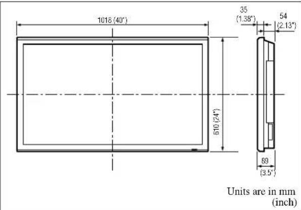
text_image
1018 (40') 610 (24') 35 (1.38°) 54 (2.13°) 89 (3.5°) Units are in mm (inch)The features and specifications may be subject to change without notice.
*1 HD/DVD/DTV input signals supported on this system
480P (60 Hz) 480I (60 Hz)
525P (60 Hz) 525I (60 Hz)
576P (50 Hz) 576I (50 Hz)
625P (50 Hz) 625I (50 Hz)
720P (60 Hz) 1035I (60 Hz)
1080I (50 Hz) 1080I (60 Hz)
*2The 5-BNC connectors are used as PC2 and COMPONENT2 input. Select one of them under "BNC INPUT".
^*3 Compatible with HDCP.
Supported Signals
- 640×480P @ 59.94/60Hz
- 1920×1080I @ 50Hz
• 1280×720P @ 59.94/60Hz • 720×576P @ 50Hz
• 1920×1080I @ 59.94/60Hz • 1440 (720)×576I @ 50Hz - 720×480P @ 59.94/60Hz
• 1440 (720) × 480I @ 59.94/60Hz
Note: In some cases a signal on the plasma monitor may not be displayed properly. The problem may be an inconsistency with standards from the source equipment (DVD, Set-top box, etc...). If you do experience such a problem please contact your dealer and also the manufacturer of the source equipment.
Mode d'emploi
RISQUE D'ELECTROCUTION NE PAS OUVRIR

ATTENTION: POUR EVITER TOUT RISQUE D'ELECTROCUTION, NE PAS OUVRIR LE BOITIER. AL'INTERIEUR, AUCUNE PIECE NE NECESSITE L'INTER-VENTION DE L'UTILISATEUR. EN CAS DE PROBLEME, S'ADRESSER A UN REPARATEUR SPECIALISTE.


Haut-parleurs: PDP-S32-LR
Support plateau: PDK-TS09
natural_image
Isometric illustration of a flat-screen monitor mounted on a base with a wavy pattern underneath (no text or symbols)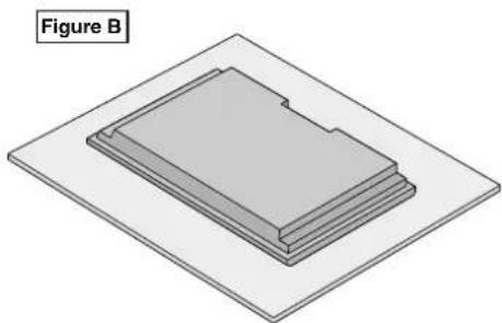
natural_image
Isometric diagram of a layered electronic component labeled Figure B, showing a rectangular structure with a notch and base plate (no text or symbols on the diagram itself)text_image
Mur 50mm (2") 50mm (2") nm (2") Mur 50mm (2") 50 50mm (2")natural_image
Diagram showing a mechanical clamp or bracket assembly with directional arrows indicating movement (no text or symbols)natural_image
Illustration of a remote control device with a black arrow pointing to a button (no text or symbols)natural_image
Technical illustration of a mechanical clamp or bracket component (no text or symbols visible)natural_image
Technical line drawing of a mechanical tool or clamp (no text or symbols)text_image
Pioneer Approx. 7m/23 pieds 30° 30°text_image
C E F G H I J K D A, BA AC IN (ENTREE DU CORDON D'ALIMENTATION ELECTRIQUE CA)
natural_image
Geometric diagram with four circles and diagonal lines forming a cross pattern (no text or symbols)natural_image
Geometric diagram with four circles arranged in a cross pattern within a rectangle (no text or symbols)natural_image
Geometric diagram with concentric circles and diagonal lines inside a rectangle (no text or symbols)natural_image
Geometric diagram with concentric circles and intersecting lines, no text or symbols presentnatural_image
Pure geometric diagram with circles and diagonal lines inside a rectangle, no text or symbols presentnatural_image
Geometric diagram with a circle and two diagonal lines inside a rectangle (no text or symbols)natural_image
Geometric pattern with four circles and diagonal lines forming a cross (no text or symbols)natural_image
Geometric diagram with intersecting circles and diagonal lines inside a rectangle (no text or symbols)natural_image
Geometric diagram with concentric circles and semicircles inside a rectangle (no text or symbols)natural_image
Pure geometric diagram with intersecting circles and diagonal lines inside a rectangle (no text or symbols)Informations
text_image
Scanned screenshot of a software dialog box with Chinese text, showing file path and file name input.| NO. 1 | NO. 2 |
| NO. 4 | NO. 3 |
| NO. 7 | NO. 8 | NO. 9 |
| NO. 10 | NO. 11 | NO. 12 |
| NO. 13 | NO. 14 | NO. 15 |
16 écrans 25 écrans
| NO. 16 | NO. 17 | NO. 18 | NO. 19 |
| NO. 20 | NO. 21 | NO. 22 | NO. 23 |
| NO. 24 | NO. 25 | NO. 26 | NO. 27 |
| NO. 28 | NO. 29 | NO. 30 | NO. 31 |
| NO. 32 | NO. 33 | NO. 34 | NO. 35 | NO. 36 |
| NO. 37 | NO. 38 | NO. 39 | NO. 40 | NO. 41 |
| NO. 42 | NO. 43 | NO. 44 | NO. 45 | NO. 46 |
| NO. 47 | NO. 48 | NO. 49 | NO. 50 | NO. 51 |
| NO. 52 | NO. 53 | NO. 54 | NO. 55 | NO. 56 |
AFFICHAGE
flowchart
graph TD
    A["Display 1"] --> B["No.1 No.2"]
    A --> C["No.4 No.3"]
    D["Display 2"] --> E["No.1 No.2"]
    D --> F["No.4 No.3"]
    G["Display 3"] --> H["No.1 No.2"]
    G --> I["No.4 No.3"]
    J["Display 4"] --> K["No.1 No.2"]
    J --> L["No.4 No.3"]
    M["Remote OUT"] --> N["Display 1"]
    O["Remote IN"] --> P["Display 2"]
    Q["Remote OUT"] --> R["Display 3"]
    S["Remote IN"] --> T["Display 4"]
natural_image
3D diagram of a layered electronic component labeled 'Zeichnung B' (no other text or symbols)text_image
Wand 50mm (2") 50mm (2') 50mm (2') Wand 50mm (2') 50 50mm (2')natural_image
Diagram showing a mechanical clamp or spring mechanism with directional arrows indicating movement (no text or symbols)natural_image
Diagram of a remote control device with a black arrow indicating the internal component (no text or symbols present)natural_image
Technical illustration of a mechanical component with a black arrow indicating a specific feature (no text or symbols present)natural_image
Technical line drawing of a mechanical clamp or bracket component (no text or symbols)text_image
C E F G H I J K D A, BA AC IN (Netzeingang)
natural_image
Geometric diagram with four circles arranged in a cross pattern, no text or symbols presentnatural_image
Pure geometric diagram with intersecting circles and diagonal lines inside a rectangle (no text or symbols)natural_image
Geometric diagram with a central circle and surrounding circles, no text or symbols presentnatural_image
Geometric diagram with concentric circles and semicircles inside a rectangle (no text or symbols)natural_image
Geometric diagram with a circle inscribed in a rectangle and two diagonal lines crossing at the center (no text or symbols)natural_image
Geometric pattern with four circles and intersecting lines forming a cross shape (no text or symbols)natural_image
Geometric diagram with intersecting circles and diagonal lines inside a rectangle (no text or symbols)natural_image
Geometric pattern with concentric circles and intersecting lines, no text or symbols presentnatural_image
Pure geometric diagram with intersecting circles and diagonal lines inside a rectangle (no text or symbols)Information
| NO. 1 | NO. 2 |
| NO. 4 | NO. 3 |
| NO. 7 | NO. 8 | NO. 9 |
| NO. 10 | NO. 11 | NO. 12 |
| NO. 13 | NO. 14 | NO. 15 |
Per attaccare i nuclei in ferrite:
Comandi OSD (On Screen Display) 11
□ Centri in ferrite (grande 2 pcs, piccolo 2pcs)
□ Bande (2pcs)
natural_image
Isometric illustration of a flat-screen monitor mounted on a stand with a wavy base and a small device attached (no text or symbols)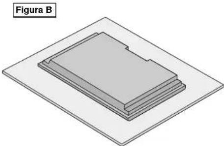
natural_image
3D diagram of a layered mechanical component labeled Figura B, showing no text or symbols on the object itself.text_image
50mm (2") 50mm (2') 50mm (2') 50mm (2') 50 50mm (2'') 50mm (2'')natural_image
Illustration of a remote control device with a black arrow pointing to the internal component (no text or symbols)natural_image
Technical illustration of a mechanical component with a black arrow indicating a specific part (no text or symbols present)natural_image
Technical line drawing of a mechanical clamp or bracket component (no text or symbols)text_image
Pioneer Circa 7m/23 piedi 30° 30°text_image
C E F G H I J K D A, BA AC IN
natural_image
Geometric diagram with four circles arranged in a cross pattern, no text or symbols presentnatural_image
Geometric diagram with four circles and diagonal lines inside a rectangle (no text or symbols)natural_image
Geometric diagram with a central circle and four surrounding circles, no text or symbols present.natural_image
Geometric diagram with concentric circles and intersecting lines inside a rectangle (no text or symbols)natural_image
Pure geometric diagram with circles and diagonal lines inside a rectangle, no text or symbols presentnatural_image
Geometric diagram with a circle inscribed in a rectangle and two diagonal lines, no text or symbols present.natural_image
Geometric pattern with four circles and diagonal lines forming a cross shape (no text or symbols)natural_image
Geometric diagram with intersecting circles and diagonal lines inside a rectangle (no text or symbols)natural_image
Geometric diagram with concentric circles and semicircles inside a rectangle (no text or symbols)natural_image
Pure geometric diagram with intersecting circles and diagonal lines inside a rectangle (no text or symbols)Informazioni
text_image
R.ALTO 70Informazioni
text_image
PROGRAM. TIMER DATA ON OFF INPUT FUNZIONE LUN 08 : 30 10 : 30 PC2.INVERSE — --- --- — — — --- --- — — — --- --- — — — --- --- — — — --- --- — — — --- --- — — SEL. ZOOM ADJ. EXIT INVIOInformazioni
| NO. 1 | NO. 2 |
| NO. 4 | NO. 3 |
| NO. 7 | NO. 8 | NO. 9 |
| NO. 10 | NO. 11 | NO. 12 |
| NO. 13 | NO. 14 | NO. 15 |
16 Schermi 25 Schermi
| NO. 16 | NO. 17 | NO. 18 | NO. 19 |
| NO. 20 | NO. 21 | NO. 22 | NO. 23 |
| NO. 24 | NO. 25 | NO. 26 | NO. 27 |
| NO. 28 | NO. 29 | NO. 30 | NO. 31 |
| NO. 32 | NO. 33 | NO. 34 | NO. 35 | NO. 36 |
| NO. 37 | NO. 38 | NO. 39 | NO. 40 | NO. 41 |
| NO. 42 | NO. 43 | NO. 44 | NO. 45 | NO. 46 |
| NO. 47 | NO. 48 | NO. 49 | NO. 50 | NO. 51 |
| NO. 52 | NO. 53 | NO. 54 | NO. 55 | NO. 56 |
DISP. MODE
flowchart
graph TD
    A["REMO TE IN"] --> B["Display 1"]
    B --> C["No.1 No.2 No.3 No.4 REMOTE OUT"]
    B --> D["Display 2"]
    D --> E["No.1 No.2 No.3 No.4 REMOTE OUT"]
    D --> F["Display 3"]
    F --> G["No.1 No.2 No.3 No.4 REMOTE OUT"]
    F --> H["Display 4"]
    H --> I["No.1 No.2 No.3 No.4 REMOTE OUT"]
flowchart
graph TD
    A["Display 1"] --> B["No.1 No.2"]
    A --> C["No.3 No.4"]
    D["Display 2"] --> E["No.1 No.2"]
    D --> F["No.3 No.4"]
    G["Display 3"] --> H["No.1 No.2"]
    G --> I["No.3 No.4"]
    J["Display 4"] --> K["No.1 No.2"]
    J --> L["No.3 No.4"]
    M["Remote OUT"] --> N["Display 1"]
    O["Remote IN"] --> P["Display 1"]
    Q["Remote OUT"] --> R["Display 2"]
    S["Remote IN"] --> T["Display 4"]
Altavoces: PDP-S32-LR
Soporte de mesa: PDK-TS09
natural_image
Illustration of a flat-screen monitor with a wavy base and a cushioned tray, labeled 'Ilustración A' (no other text or symbols)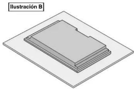
natural_image
3D diagram of a layered rectangular object with a label 'Ilustración B' (no other text or symbols)text_image
Pared 50mm (2°) 50mm (2°) 50mm (2°) 50mm (2°) 50 Pared 50mm (2°)natural_image
Diagram showing a belt buckle being adjusted with arrows indicating motion (no text or symbols)natural_image
Diagram of a remote control device with a black arrow indicating a component (no text or symbols present)natural_image
Technical illustration of a mechanical component with a black arrow indicating a specific part (no text or symbols present)- Instale la tapa.
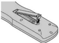
natural_image
Technical line drawing of a mechanical clamp or bracket component (no text or symbols)text_image
Pioneer Aprox. 7m/23pies 30° 30°text_image
C E F G H I J K D A, BA AC IN
natural_image
Geometric diagram with four circles arranged in a cross pattern, no text or symbols presentnatural_image
Geometric diagram with four circles arranged in a cross pattern within a rectangle (no text or symbols)natural_image
Geometric diagram with concentric circles and intersecting lines inside a rectangle (no text or symbols)natural_image
Geometric diagram with concentric circles and semicircles inside a rectangle (no text or symbols)natural_image
Pure geometric diagram with circles and diagonal lines inside a rectangle, no text or symbols presentnatural_image
Geometric diagram with a circle and intersecting lines inside a rectangle (no text or symbols)natural_image
Geometric pattern with four circles and diagonal lines forming a cross (no text or symbols)natural_image
Geometric pattern with intersecting circles and diagonal lines inside a rectangle (no text or symbols)natural_image
Geometric diagram with concentric circles and semicircles inside a rectangle (no text or symbols)natural_image
Pure geometric diagram with intersecting circles and diagonal lines inside a rectangle (no text or symbols)Información
DAYLITE SAVE: Para ajustar DAYLITE SAVE.
| NO. 1 | NO. 2 |
| NO. 4 | NO. 3 |
| NO. 7 | NO. 8 | NO. 9 |
| NO. 10 | NO. 11 | NO. 12 |
| NO. 13 | NO. 14 | NO. 15 |
flowchart
graph TD
    A["Display 1"] --> B["No.1 No.2"]
    A --> C["No.3 No.4"]
    D["Display 2"] --> E["No.1 No.2"]
    D --> F["No.3 No.4"]
    G["Display 3"] --> H["No.1 No.2"]
    G --> I["No.3 No.4"]
    B --> J["REMOTE OUT"]
    C --> K["REMOTE IN"]
    E --> L["REMOTE OUT"]
    H --> M["REMOTE IN"]
    I --> N["REMOTE IN"]
natural_image
Illustration of a monitor mounted on a stand with a wavy pattern underneath (no text or symbols)
natural_image
3D diagram of layered rectangular blocks on a flat base, labeled 'Рисунок B' (no other text or symbols)natural_image
Technical illustration of a mechanical component with mounting holes and a central internal mechanism (no text or symbols)text_image
C E F G H I J K D A, BА Вывод АС ИН
natural_image
Geometric pattern with four circles and diagonal lines forming a cross (no text or symbols)natural_image
Geometric diagram with intersecting circles and diagonal lines inside a rectangle (no text or symbols)natural_image
Geometric diagram with concentric circles and diagonal lines inside a rectangle (no text or symbols)natural_image
Geometric diagram with concentric circles and semicircles inside a rectangle (no text or symbols)natural_image
Pure geometric diagram with circles and diagonal lines inside a rectangle, no text or symbols presentnatural_image
Geometric diagram with a circle inscribed in a rectangle and two diagonal lines crossing at the center (no text or symbols)natural_image
Geometric pattern with intersecting circles and diagonal lines forming a symmetrical design (no text or symbols)natural_image
Geometric diagram with intersecting circles and diagonal lines inside a rectangle (no text or symbols)natural_image
Pure geometric diagram with intersecting circles and diagonal lines inside a rectangle (no text or symbols)Информация
text_image
Scanned document with Chinese text, likely a form or report section with bullet points and checkboxes.natural_image
3D diagram of a mechanical component labeled 'Tekening A' with no visible text or symbols on the main structure itself.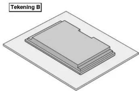
natural_image
3D diagram of layered electronic components labeled 'Tekening B' (no other text or symbols)natural_image
Diagram of a remote control panel with a black arrow indicating a location or movement (no text or symbols present)natural_image
Technical illustration of a mechanical component with a highlighted internal section (no text or symbols)natural_image
Technical line drawing of a mechanical clamp or bracket component (no text or symbols)text_image
C E F G H I J K D A, BA AC IN
natural_image
Geometric pattern with four circles and diagonal lines forming a cross shape (no text or symbols)natural_image
Geometric diagram with intersecting circles and diagonal lines inside a rectangle (no text or symbols)natural_image
Geometric pattern with a central circle and four surrounding circles, no text or symbols present.natural_image
Geometric pattern with concentric circles and intersecting lines forming a symmetrical design (no text or symbols)natural_image
Pure geometric diagram with circles and diagonal lines inside a rectangle, no text or symbols presentnatural_image
Geometric diagram with a circle inscribed in a rectangle and two diagonal lines, no text or symbols present.natural_image
Geometric pattern with intersecting circles and diagonal lines forming a cross (no text or symbols)natural_image
Geometric diagram with intersecting circles and diagonal lines inside a rectangle (no text or symbols)natural_image
Geometric pattern with concentric circles and intersecting lines forming a symmetrical design (no text or symbols)natural_image
Pure geometric diagram with intersecting circles and diagonal lines inside a rectangle (no text or symbols)Informatie
"WORKING TIME" 01u30m
"WAITING TIME" 02u00m
←----2u ----*----1,5u ----→|←---- Start Start invers/wit Stand-by
■ Instellen van "WORKING TIME" op "ON"
| PROGRAM TIMER | ||||
| DATE | ON | OFF | INPUT | FUNCTION |
| MON | 08 : 30 | 10 : 30 | PC2 | INVERSE |
| — | --- | --- | — | — |
| — | --- | --- | — | — |
| — | --- | --- | — | — |
| — | --- | --- | — | — |
| — | --- | --- | — | — |
| — | --- | --- | — | — |
| SEL. | ZOOM | ADJ. | EXIT | RETURN |
Informatie
■ PROGRAM TIMER-instellingen
| NO. 1 | NO. 2 |
| NO. 4 | NO. 3 |
| NO. 7 | NO. 8 | NO. 9 |
| NO. 10 | NO. 11 | NO. 12 |
| NO. 13 | NO. 14 | NO. 15 |
16 scherm 25 scherm
| NO. 16 | NO. 17 | NO. 18 | NO. 19 |
| NO. 20 | NO. 21 | NO. 22 | NO. 23 |
| NO. 24 | NO. 25 | NO. 26 | NO. 27 |
| NO. 28 | NO. 29 | NO. 30 | NO. 31 |
| NO. 32 | NO. 33 | NO. 34 | NO. 35 | NO. 36 |
| NO. 37 | NO. 38 | NO. 39 | NO. 40 | NO. 41 |
| NO. 42 | NO. 43 | NO. 44 | NO. 45 | NO. 46 |
| NO. 47 | NO. 48 | NO. 49 | NO. 50 | NO. 51 |
| NO. 52 | NO. 53 | NO. 54 | NO. 55 | NO. 56 |
DISP. MODE
flowchart
graph TD
    A["No.1"] --> B["No.2"]
    C["No.3"] --> D["No.4"]
    E["No.1"] --> F["No.2"]
    G["No.3"] --> H["No.4"]
    I["No.1"] --> J["No.2"]
    K["No.3"] --> L["No.4"]
    M["No.1"] --> N["No.2"]
    O["No.3"] --> P["No.4"]
    Q["No.1"] --> R["No.2"]
    S["No.3"] --> T["No.4"]
    U["No.1"] --> V["No.2"]
    W["No.3"] --> X["No.4"]
    Y["No.1"] --> Z["No.2"]
    AA["No.3"] --> AB["No.4"]
text_image
MAIN MENU 1 / 2 PICTURE SOUND SCREEN OPTION1 OPTION2 OPTION3 ADVANCED OSD : ON ▶ ↓ NEXT PAGE SEL. ▶ ADJ. EXIT EXITInformatie
■ ADVANCED OSD-instellingen
Published by Pioneer Corporation.
Copyright © 2004 Pioneer Corporation.
All rights reserved.
Издано Pioneer Corporation.