
RC-6421 - Walkie-talkie TRISTAR - Free user manual and instructions
Find the device manual for free RC-6421 TRISTAR in PDF.

| Product type | License-free PMR446 two-way radio |
| Brand | TriStar |
| Model | RC-6421 |
| Number of channels | 16 (channels 1-8 with DCS code, 9-16 without code) |
| Maximum range | 10 km under optimal conditions |
| Transmit power | 0.5 Watt |
| Frequency | 446 MHz (PMR446 band) |
| Power supply | Rechargeable Li-ion battery |
| Charging time | Approximately 3.5 hours |
| Protection rating | IP54 (dust and splash water resistant) |
| Main functions | Voice communication, 16 channels, voice scrambling, channel scanning, monitor function, VOX (optional), compander, whisper mode, alarm |
| Included accessories | Belt clip, desktop charger, power adapter, Li-ion battery, strap, user manual |
| External connectivity | Jack for external speaker/microphone and PC cable |
| Antenna | Fixed non-removable antenna |
| Cleaning and maintenance | Soft damp cloth, avoid solvents; dry completely after water contact |
| Safety | Do not touch damaged antenna; keep at least 15 cm away from pacemakers; turn off in explosive areas |
| Warranty | 24 months (excluding batteries and accessories) |
| Country of origin | Not specified |
Frequently Asked Questions - RC-6421 TRISTAR
User questions about RC-6421 TRISTAR
0 question about this device. Answer the ones you know or ask your own.
Ask a new question about this device
Download the instructions for your Walkie-talkie in PDF format for free! Find your manual RC-6421 - TRISTAR and take your electronic device back in hand. On this page are published all the documents necessary for the use of your device. RC-6421 by TRISTAR.
USER MANUAL RC-6421 TRISTAR
natural_image
Black office walkie-talkie with a tall antenna and three speakers (no visible text or symbols)TOPCOM®
Protalker PT-1116
User guide
Handleiding
Thank you for purchasing the Topcom Protalker PT-1116. This PMR radio a high quality, long range and low powered radio communication device with a range of maximum 10 Km in optimal conditions. It has no running costs other than the minimal cost of re-charging the batteries.
The Protalker PT-1116 operates in the licence-free PMR 446 MHz frequency band and can operate on 8 different radio frequencies.
The rotatable channel selector has 16 positions :
- Channel 1..8 : the 8 PMR446 frequencies + a pre-defined DCS sub-channel code.
- Channel 9..16 : the 8 different PMR446 frequencies without any DCS sub-channel code.
In accordance with the PMR446 regulations, the radiated power of this radio is 0.5 Watts and the antenna cannot be removed from the body. The PT-1116 complies to the IP54 standard so it can operate in dusty environments and it is splash waterproof. Thanks to the high quality speaker you will always receive a very loud and clear audio signal.
2 C E M a r k
The CE symbol on the unit, user guide and giftbox indicates that the unit complies with the essential requirements of the R&TTE directive 1995/5/EC.
3 Safety instructions
3.1 General
Please read carefully through the following information concerning safety and proper use. Make yourself familiar with all functions of the device. Keep this manual in a safe place for future use.
3.2 Burning injuries
- If the cover of the antenna is damaged, do not touch because when an antenna comes in contact with the skin, a minor burn may result when transmitting.
- Batteries can cause property damage such as burns if conductive material such as jewellery, keys or beaded chains touches exposed terminals. The material may complete an electrical circuit (short circuit) and become quite hot. Exercise care in handling any charged battery, particularly when placing it inside a pocket, purse or other container with metal objects.
3.3 Injuries
- Do not place your device in the area over an air bag or in the air bag deployment area. Air bags inflate with great force. If a PMR is placed in the bag deployment area and the air bag inflates, the communicator may be propelled with great force and cause serious injury to the occupants of the vehicle.
- Keep the PMR at least 15 centimetres away from a pacemaker.
- Turn your PMR OFF as soon as interference is taking place with medical equipment.
3.4 Danger of explosion
- Do not replace batteries in a potentially explosive atmosphere. Contact sparking may occur while installing or removing batteries and cause an explosion.
• Turn your PMR off when in any area with a potentially explosive atmosphere. Sparks in such areas could cause an explosion or fire resulting in bodily injury or even death. - Never throw batteries in fire as they may explode.

Areas with potentially explosive atmospheres are often, but not always, clearly marked. They include fuelling areas such as below deck on boats, fuel or chemical transfer or storage facilities; areas where the air contains chemicals or particles, such as grain, dust or metal powders; and any other area where you would normally be advised to turn off your vehicle engine.
3.5 Poisoning danger
- Keep batteries away from small children.
3.6 Legal
- In some countries it is prohibited to use you r PMR while driving a vehicle. In this case leave the road before using the device.
- Turn your PMR OFF when on board an aircraft w hen instructed to do so. Any use of the PMR must be in accordance with airline regulations or crew instructions.
- Turn your PMR OFF in any facilities where posted notices instruct you to do so. Hospitals or health care facilities may be using equipment that is sensitive to external RF energy.
- Replacing or modifying the antenna may affect the PMR radio specifications and violate the CE regulations. Unauthorised antennas could also damage the radio.
3.7 Notes
- Do not touch the antenna while transmitting, it could affect the range.
- Remove the batteries if the device is not going to be used for a long period.
4 Cleaning and maintenance
- To clean the unit, wipe with a soft cloth dampened with water. Don't use a cleaner or solvents on the unit; they can damage the case and leak inside, causing permanent damage.
- Battery contacts may be wiped with a dry lint-free cloth.
- If the unit gets wet, turn it off and remove the batteries immediately. Dry the battery compartment with a soft cloth to minimize potential water damage. Leave the cover off the battery compartment overnight or until completely dry. Do not use the unit until completely dry.
5 Disposal of the device (environment)

At the end of the product lifecycle, you should not throw this product into the normal household garbage but bring the product to a collection point for the recycling of electrical and electronic equipments. The symbol on the product, user guide and/or box indicate this.
Some of the product materials can be re-used if you bring them to a recycling point. By re-using some parts or raw materials from used products you make an important contribution to the protection of the environment. Please contact your local authorities in case you need more information on the collection points in your area.
Protalker 1116
6 Using a PMR 446 Mhz radio
To communicate between PMR devices they need to be set all on the same frequency + sub-channel code and within receiving range (up to max. 10 km in ideal conditions). Since the PT-1116 operates on licence free 446 MHz frequencies, all other licence free 446 MHz PMR radio's will operate on the same radio frequencies. Therefore, privacy is not guaranteed. Anybody with a PMR set to your radio frequency can overhear the conversation. If you want to communicate (transmitting a voice signal) you need to press the PTT-button. Once this button pressed, the device will go into transmit mode and you can speak into the microphone. All other PMR devices in range, on the same channel and in standby mode (not transmitting) will hear your message. You need to wait until the other party stops transmitting before you can reply to the message. To reply, just press the PTT-button and speak into the microphone..

If 2 or more users press the PTT- button at the same time the receiver will receive only the stongest signal and the other signal(s) will be suppressed. Therefore you should only transmit a signal (press PTT- button) when the channel is free.

The range of radio waves is strongly affected by obstacles such as buildings, concrete/metal structures, the unevenness of the landscape, woodland, plants, humidity ... This implies that the range between two or more PMR's may in some extreme cases be restricted to a maximum of a few tens of meters. You will soon notice that PMR works best when there is a minimum of obstacles between users.
7 Included in the package
• 1 x Protalker PT-1116
- 1 x Beltclip
• 1 x Desktop Charger
- 1 x Power adapter
- 1 x Li-ion battery
• 1 x ECO User guide
8 Getting started
8.1 Installing the battery pack

Align the battery pack with the back of the PMR body. Press the battery pack and PMR body firmly together until the release latch locks up the battery.
8.2 Removing the battery pack

While pressing the release latch, pull the battery pack away from the PMR body
8.3 Installing the belt clip

natural_image
Technical line drawing of a vintage camera with two views: one showing internal components and the other showing a mounted device (no text or symbols present)Remove the screw on the back of the radio, put the clip button on, and fix it with the screw. Match the grooves of the belt clip with the button, push the belt clip downwards until it is locked.
8.4 Removing the belt clip
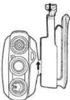
Push the spring of the belt clip supporter downwards and push the belt clip puwards to remove it from the radio.
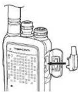
8.5 Installing the hand strap

natural_image
Line drawing of a hand holding a bottle with a cap, no text or symbols presentSlide the small loop of the hand strap through the strap hole on the upper rear of the PMR body. Pull the entire hand strap through the small loop to secure the hand strap in place.
Protalker 1116
8.6 Charging the battery
-
Connect the power jack of the power adapter to the back of the desktop charger.
-
Plug in the power adapter in an easy accessible power socket.
Put in the PMR (with installed battery) or the separate battery into the charger.

The LED colour will indicate the charging status of the battery:
• Red : Charging
• Green : Fully charged
When the battery is fully discharged it will take about 3.5 hours to charge the battery.

Do not use the PMR while charging the battery. Switch off the power of the PMR while charging.

Do not short-circuit the batteries or dispose in fire. Remove the batteries if this device is not going to be used for a long period.
9 The PMR radio

- Fixed antenna
- Channel selector (16 positions)
- On/Off, Volume rotatable knob
- External Speaker/Microphone, PC cable connector
- Speaker
- Microphone
- Function key 1
- Function key 2
- PTT-button
-
Status LED
-
Green : Receiving
- Red blinking : Scanning
-
Red : Transmitting
– Green blinking : Battery status indication -
Strap hole
- Belt clip
- Battery
6
Protalker 1116
10 Using the PMR radio
10.1 Switching On/Off the PMR radio
- Turn the "On-Off/Volume knob" Ⓤ clockwise. A clicking sound will indicate that the PMR radio is switched on.
- Adjust the volume level by turning the knob
- Turn the "On-Off/Volume knob" ③ fully counter clockwise. The clicking sound will indicate that the PMR radio is switched off.

Do not short-circuit the batteries or dispose in fire. Remove the batteries if this device is not going to be used for a long period.
10.2 Selecting the channel
The PT-1116 is pre-programmed with 16 channels. It is recommended to use the first eight channels (1..8) as these are a combination of a radio frequency combined with a DCS sub-channel code. This way, there will be less interference of other PMR 446MHz users on your channel. Last eight channels (9..16) are the eight different radio frequencies and will allow you to speak/listen to users who are using PMR 446 MHz radio's that are not using sub-channel codes.
- Rotate the "Channel selector" ② to select the desired channel.
The table in Annex A shows how the PT-1116 channels are pre-programmed.
When using the optional PC programming cable and the programming software, downloadable from the Topcom website "www.topcom.net", you will be able to reprogram the channel frequencies, DCS/CTCSS sub-channel, function keys and other features.
10.3 Battery status
When PMR radio is switched on, the Status LED ⑩ will indicate the battery status.
- 4 x blinking green : 80\~100% battery power left.
-3 x blinking green: 50\~80% battery power left.
- 2 x blinking green : 20\~50% battery power left.
- 1 x blinking green : 5\~20% battery power left.
The status LED will blink red slowly and the voice prompt will inform you when need to recharge the battery.
10.4 Transmitting a signal
Press the PTT - button ⑨ and speak towards the microphone. The ideal distance between the microphone of the PMR radio and your mouth is 5 to 10 cm.
The Status LED ⑩ will turn red while transmitting.
10.5 Receiving a signal
When the PT-1116 is turned ON it will always be in receiving mode on the selected channel. While receiving a signal you can always adjust the volume by turning the knob ③.
The Status LED ② will turn green when receiving a signal.
10.6 Function keys
The PT-1116 has two function keys. By default, two functions are preprogrammed to each key. When using the optional PC programming cable and the software you can assign other features to the function keys.
10.6.1 Scanning
When you press briefly Function key 1 ⑦ the PMR radio will scan for signals on the first 8 channels (1..8). In this way, the PMR radio will scan for signals coming from other PT-1116 users or from users operating on the same radio frequency with the same DCS sub-channel. (Annex A)
The Status LED ⑩ will blink red while scanning. When a signal is received you can answer just by pressing the PPT-button ⑨. The scanning will resume automatically after 4 seconds.
When you press briefly Function key 1 ⑦ agian, scanning will be disabled.
10.6.2 Voice scrambling
When pressing Function key 1 ⑦ for at least 1.5 seconds, voice scrambling will be enabled. This way, other PMR radio's without this function will not be able to understand you when you are transmitting.
When pressing Function key 1 ⑦ for at least 1.5 seconds again, voice scrambling will be disabled.

Make sure all users enable voice scrambling at the same time to make sure that they understand each other.
10.6.3 Annunciation Elimination
By default, the PMR will announce the channel number and functions by an english voice prompt.
You can choose between voice prompt, a beep tone, or silence.
Press briefly Function key 2 ⑧ to toggle between the three options.
10.6.4 Monitor
When you press function key 2⑧ for at least 1.5 seconds, the monitor function will be enabled. You will be able to hear weaker signals.
Press function key 2 ⑧ for at least 1.5 seconds again to disable monitoring.
Protalker 1116
10.6.5 Other functions
By use of the optional PC programming cable and the downloadable programming software, you can assign other functions to both function keys:
• Alarm : sending an alerting tone to other PT-1116 users
- Battery power check: check the battery status
- Whisper: activate an extra microphone amplifier or so you can whisper in the microphone if required. The receiving PMR radio will understand you better. In normal conditions, whisper mode should be disabled.
- VOX : enable/disable VOX : only when using a VOX headset with VOX switch. Not all headsets support VOX-mode !!
- Compander: enable/disable voice compressing for extra clear modulation (noise reduction). It is recommenced that all users enable the compander at the same time for optimal result.
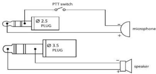
11 External speaker/microphone connection
You can connect an optional speaker/microphone (shoulder microphone, ear tube, PC programming cable,...) via the side panel connectors. ④
Insert the speaker/microphone plug into the speaker/microphone jack of the PT-1116.
The diagram in Annex B shows how the speaker/microphone is connected.
12 VOX
By use of the optional PC programming cable and the downloadable programming software you can enable VOX in the radio.
When using a VOX-headset make sure to follow the steps below :
- Enable VOX by use of the PC software
- Switch off the PT-1116
- Set the headset switch to VOX
- Insert the speaker/microphone plug of the headset into the speaker/microphone jack of the PT-1116.
- Switch back on the PT-1116.
13 Technical specifications
Please refer to Annex C for the technical specifications.
14 Warranty
14.1 Warranty period
The devices have a 24-month warranty period. The warranty period starts on the day the new unit is purchased. There is no warranty on standard or rechargeable batteries. Consumables or defects causing a negligible effect on operation or value of the equipment are not covered. The warranty has to be proven by presentation of the original or copy of the purchase receipt, on which the date of purchase and the unit-model are indicated.
14.2 Warranty exclusions
Damage or defects caused by incorrect treatment or operation and damage resulting from use of non-original parts or accessories are not covered by the warranty.
The warranty does not cover damage caused by outside factors, such as lightning, water and fire, nor any damage caused during transportation. No warranty can be claimed if the serial number on the units has been changed, removed or rendered illegible. Any warranty claims will be invalid if the unit has been repaired, altered or modified by the buyer
Protalker 1116
1 Inleiding
natural_image
Line drawing of two vintage camera modules with no visible text or symbolsnatural_image
Line drawing of a vintage typewriter with a handle and spout (no text or symbols)• 1 Protalker PT-1116
natural_image
Line drawings of three different types of vintage camera models: a cylindrical device, a multi-stage camera, and a flat case (no text or symbols present)natural_image
Line drawing of a vintage typewriter with a handle, no text or symbols presentnatural_image
Line drawings of vintage camera modules and a mechanical device (no text or symbols)natural_image
Line drawing of a vintage-style gas cylinder with a handle, no text or symbols presentnatural_image
Line drawings of vintage camera modules and a mounted device (no text or symbols)natural_image
Line drawing of a vintage typewriter with a handle and spout (no text or symbols)natural_image
Line drawings of vintage camera modules and a vintage flatset (no text or symbols)natural_image
Line drawing of a vintage digital camera with lens and screen (no text or symbols)natural_image
Technical line drawing of a vintage camera with two views: top shows a cylindrical device and side view shows a multi-stage optical device (no text or symbols)natural_image
Line drawing of a laboratory gas collection bottle with a pipette inserted (no text or symbols)Pre-programmed channels
| LENNAHC-BUSYCNE | ||
| 1 | 446.00625 | N130DzHM = D |
| 2 | 446.01875 | N150DzHM = D |
| 3 | 446.03125 | N270DzHM = D |
| 4 | 446.04375 | N511DzHM = D |
| 5 | 446.05625 | N231DzHM = D |
| 6 | 446.06875 | N551DzHM = D |
| 7 | 446.08125 | N271DzHM = D |
| 8 | 446.09375 | N622DzHM = D |
| 9 446.00625 MHz - | ||
| 10 446.01875 MHz - | ||
| 11 446.03125 MHz - | ||
| 12 446.04875 MHz - | ||
| 13 446.05625 MHz - | ||
| 14 446.06875 MHz - | ||
| 15 446.08125 MHz - | ||
| 16 446.09875 MHz - | ||
Annex C
Technical specifications
| Frequency range : | 446.00625 ... 446.09375 MHz |
| Channel spacing : | 12.5 KHz |
| Channels : | 16 |
| Maximum RF output power : | 0.5 W |
| Modulation : | FM-F3E |
| Antenna type : | Fixed |
| Audio output power : | <=500mW |
| Battery type : | 3.8V-2000mAh (Li-ion) |
| Operation temperature : | -20 °C ... +55°C |
| IP-standard : | 45PI |
| Dimensions : | 120 x 55 x 27 mm (without antenna) |
| Weight : | 165 g (including battery, antenna) |
Annex B
Speaker / microphone connection diagram
Annex D
CTCSS / DCS Chart
| CTCSS Code Chart | |||||||||
| Code | Freq | ( Hz) | Code | Freq | ( Hz) | Code | Freq | ( Hz) | Code |
| 1 67 11 | 97,4 21 136,5 | 11 192,8 | |||||||
| 2 71,9 | 2 100 22 141,3 | 32 203,5 | |||||||
| 3 74,4 | 3 103,5 23 146 | 2 33 210,7 | |||||||
| 4 77 14 | 107,2 24 151,4 | 34 218,1 | |||||||
| 5 79,7 | 5 110,9 25 156 | 7 35 225,7 | |||||||
| 6 82,5 | 6 114,8 26 162 | 2 36 233,6 | |||||||
| 7 85,4 | 7 118,8 27 167 | 9 37 241,8 | |||||||
| 8 88,5 | 8 123 28 173,8 | 38 250,3 | |||||||
| 9 91,5 | 9 127,3 29 179 | 9 | |||||||
| 10 94,8 | 10 131,8 30 180 | 2 | |||||||
| DCS Code ChartNo DCS Code No DCS Code No DCS Code | ||||||
| 21 D134N 42 D311N 63 | D516N | |||||
| 1 D023N 22 D143N 43 | D315N 64 D532N | |||||
| 2 D025N 23 D152N 44 | D331N 65 D546N | |||||
| 3 D026N 24 D155N 45 | D343N 66 D565N | |||||
| 4 D031N 25 D156N 46 | D346N 67 D606N | |||||
| 5 D032N 26 D162N 47 | D351N 68 D612N | |||||
| 6 D043N 27 D165N 48 | D364N 69 D624N | |||||
| 7 D047N 28 D172N 49 | D365N 70 D627N | |||||
| 8 D051N 29 D174N 50 | D371N 71 D631N | |||||
| 9 D054N 30 D205N 51 | D411N 72 D632N | |||||
| 10 D065N 31 D223N 52 | D412N 73 D654N | |||||
| 11 D071N 32 D226N 53 | D413N 74 D662N | |||||
| 12 D072N 33 D243N 54 | D423N 75 D664N | |||||
| 13 D073N 34 D244N 55 | D431N 76 D708N | |||||
| 14 D074 | N 35 | D245N 56 D432N 77 D712N | ||||
| 15 D114N 36 D251N 57 | D445N 78 D723N | |||||
| 16 D115N 37 D261N 58 | D464N 79 D731N | |||||
| 17 D116N 38 D263N 59 | D465N 80 D732N | |||||
| 18 D125N 39 D265N 60 | D466N 81 D733N | |||||
| 19 D131N 40 D271N 61 | D503N 82 D743N | |||||
| 20 D132N 41 D306N 62 | D506N 83 D754N | |||||
This product is in compliance with the essential requirements and other relevant provisions of the R & TTE directive 1999/5/EC.
The Declaration of conformity can be found on : http://www.topcom.net/support/cedeclarations.php
TOPCOM®
Visit our website
www.topcom.net
- TOPCOM®
- Protalker PT-1116
- C E M a r k
- Safety instructions
- General
- Burning injuries
- Injuries
- Danger of explosion
- Poisoning danger
- Legal
- Notes
- Cleaning and maintenance
- Disposal of the device (environment)
- Using a PMR 446 Mhz radio
- Included in the package
- Getting started
- Charging the battery
- Using the PMR radio
- Switching On/Off the PMR radio
- Do not short-circuit the batteries or dispose in fire. Remove the batteries if this device is not going to be used for a long period.
- Selecting the channel
- Battery status
- Transmitting a signal
- Receiving a signal
- Function keys
- Scanning
- Voice scrambling
- Make sure all users enable voice scrambling at the same time to make sure that they understand each other.
- Annunciation Elimination
- Monitor
- Other functions
- External speaker/microphone connection
- VOX
- Technical specifications
- Warranty
- Warranty period
- Warranty exclusions
- Inleiding
- Annex C
- Annex B
- Annex D
Brand : TRISTAR
Model : RC-6421
Category : Walkie-talkie