USER MANUAL CV-P09FR SHARP
natural_image
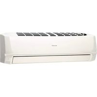
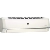
Line drawing of a portable air conditioner unit (no text or symbols)
- Uses ozone layer friendly refriderant R410A.
- Verwendet das die Ozonschicht schonende Kühlmittel R410A.
- Utilise un réfrigérant qui n'attaque pas la couche d'ozone, le R410A.
- Utilizza il refrigerante R410A che non danneggia lo strato d'ozono.
- Utiliza refrigerante R410A que no daña la capa de ozono.
- Gebruikt de ozon-vriendelijke koelvloeistof R410A.
- W urządzeniu zastosowano czynnik chłodzący (R410A) bezpieczny dla warstwy ozonowej.
PORTABLE TYPE ROOM AIR CONDITIONER
INSTALLATION AND OPERATION MANUAL
PORTABLES RAUMKLIMAGERÄT
INSTALLATIONS- UND
BEDIENUNGSHANDBUCH
CLIMATISEUR MOBILE
MANUEL D'INSTALLATION ET
D'UTILISATION
CONDIZIONATORE D'ARIA TIPO PORTATILE
MANUALE PER L'INSTALLAZIONE
E IL FUNZIONAMENTO
natural_image
Symbol of a trash bin crossed out by two crossed lines, with no text or labels present.
Attention: Your product is marked with this symbol. It means that used electrical and electronic products should not be mixed with general household waste. There is a separate collection system for these products.
1. In the European Union
Attention: If you want to dispose of this equipment, please do not use the ordinary dust bin!
Used electrical and electronic equipment must be treated separately and in accordance with legislation that requires proper treatment, recovery and recycling of used electrical and electronic equipment.
Following the implementation by member states, private households within the EU states may return their used electrical and electronic equipment to designated collection facilities free of charge*. In some countries* your local retailer may also take back your old product free of charge if you purchase a similar new one. *) Please contact your local authority for further details.
If your used electrical or electronic equipment has batteries or accumulators, please dispose of these separately beforehand according to local requirements.
By disposing of this product correctly you will help ensure that the waste undergoes the necessary treatment, recovery and recycling and thus prevent potential negative effects on the environment and human health which could otherwise arise due to inappropriate waste handling.
2. In other Countries outside the EU
If you wish to discard this product, please contact your local authorities and ask for the correct method of disposal.
For Switzerland: Used electrical or electronic equipment can be returned free of charge to the dealer, even if you don't purchase a new product. Further collection facilities are listed on the homepage of www.swico.ch or www.sens.ch.
1. In the European Union
If the product is used for business purposes and you want to discard it:
Please contact your SHARP dealer who will inform you about the take-back of the product. You might be charged for the costs arising from take-back and recycling. Small products (and small amounts) might be taken back by your local collection facilities.
For Spain: Please contact the established collection system or your local authority for take-back of your used products.
2. In other Countries outside the EU
If you wish to discard of this product, please contact your local authorities and ask for the correct method of disposal.
This manual explains the proper use of your new air conditioner. Please read this manual carefully before using the product. This manual should be kept in a safe place for handy reference.
CONTENTS
• IMPORTANT SAFETY INSTRUCTIONS ...E-1
- LOCATION ......E-3
• INCLUDED ......E-3
• PART NAMES ......E-4
• USING THE REMOTE CONTROL .....E-6
• INSTALLATION AND REMOVAL
OF EXHAUST HOSE ......E-8
• COOL MODE ....E-9
• DEHUMIDIFICATION MODE ......E-10
• FAN MODE ......E-11
• VENTILATION MODE ...... E-11
• TO CHANGE AIR FLOW DIRECTION .. E-12
• TURBO COOL OPERATION ..... E-13
- ONE-HOUR OFF TIMER ...... E-13
• TIMER OPERATION ...... E-14
- PLASMACLUSTER OPERATION ...... E-16
- AUXILIARY MODE ...... E-16
• DRAINAGE E-17
- MAINTENANCE ...... E-18
- BEFORE CALLING FOR SERVICE ..... E-19
IMPORTANT SAFETY INSTRUCTIONS
Points to keep in mind when using your air conditioner.
WARNINGS FOR USE
- Do not modify any part of this product.
- Do not insert anything into any part of the unit.
- Ensure the power supply used has an appropriate voltage rating.
Only use a 220 V – 240 V, 50 Hz, 10 A mains electricity supply.
Use of a power supply with an improper voltage rating can result in damage to the unit and possibly re.
• Always use a fuse with the proper amp rating.
Do not, under any circumstances, use wire, pins or other objects in place of a proper fuse.
- In the event of any abnormality with the air conditioner (ex. a burning smell), turn it off immediately and disconnect the power supply.
WARNING FOR POWER SUPPLY CORD
- This power plug must only be plugged into an appropriate wall socket. Do not use in conjunction with any extension cords.
- Push the power plug securely into the socket and make sure it is not loose.
- Do not pull, deform, or modify the power supply cord, or immerse it in water.
Pulling or misuse of the power supply cord can result in damage to the unit and cause electrical shock.
- If the supply cord is damaged, it must be replaced by the manufacturer or its service agent or a similarly qualified person in order to avoid a hazard. Use only the manufacture-speci ed power cord for replacement.
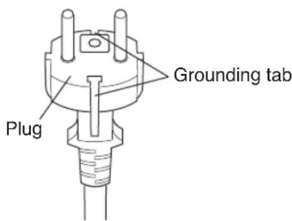
- This appliance must be grounded.
This appliance is equipped with a cord having a grounding wire with a grounding tab. The plug must be plugged into an outlet that is properly installed and grounded.
USAGE CAUTIONS
- Ventilate the room periodically during use, especially if using gas appliances.
- Be sure to turn the unit off and disconnect the power supply cord before performing any maintenance or cleaning.
- Do not splash or pour water directly onto the unit.
Water can cause electrical shock or equipment damage.
- Drainage should be performed whenever moving the air conditioner. (See Page 17)
If any water remains in the tank, it may spill out while being moved.
- To ensure proper drainage, the drainage hose must have no kinks or be on a different level during dehumid i cation mode.
The drained water may spill out into the room.
- The temperature around the drainage hose must not be below freezing point when used.
Drained water may freeze inside the hose, causing water inside the unit to over ow into the room.
- Do not block the exhaust air outlet with obstacles.
Cooling performance may be reduced or stop completely.
- Provide an earth leakage breaker in order to protect against electric shock in case of leak. Use the current-activated, high-sensitivity, high-speed type breaker with a rated sensitivity current of below 30 mA and an operating time of below 0.1 second.
NOTES ON OPERATION
- Allow 3 minutes for the compressor to restart cooling.
If you turn the air conditioner off and immediately restart it, allow three minutes for the compressor to restart cooling. There is an electronic device in the unit that keeps the compressor turned off for three minutes for safety.
• In the event of a power failure during use, allow 3 minutes before restarting the unit.
After power is reinstated, restart the air conditioner. If the power was off for less than three minutes, be sure to wait at least three minutes before restarting the unit. If you restart the air conditioner within three minutes, a protective device in the unit may cause the compressor to shut off. This protective device will prevent cooling for about 5 minutes. Any previous settings will be canceled and the unit will return to its initial settings.
- Low temperature operation: Is your unit freezing up?
Freezing may occur when the unit is set close to 18^ C in low ambient temperature conditions, especially at night.
In these conditions, a further temperature drop may cause the unit to freeze.
Setting the unit to a higher temperature will prevent it from freezing.
- Dehumidiation mode increases room temperature.
The unit generates heat during dehumidication mode and the room temperature will rise. Warm air will be blown out from the Exhaust air outlet, but this is normal and does not indicate a problem with the unit.
- This air conditioner blows the warm air generated by the unit outside the room via the exhaust hose while in cool mode.
Accordingly, the same amount of air as that blown out will enter the room from outside through any openings into the room.
OPERATING CONDITIONS
- The air conditioner must be operated within the temperature range indicated below.
| Mode Room temperature |
| COOL | upper limit | *40°C |
| lower limit | 18°C |
| DEHUMIDIFICATION | lower limit | 15°C |
- A built-in safety device may cut off operation if the temperature exceeds these limits.
- When cooling operation is performed at high room temperature, the fan may run slightly slowed
* Available for operation at condition of supply voltage 220 V or over, not exceeding 240 V.
ENERGY EFFICIENCY TIPS
- Avoid direct sunlight.
Close blinds, drapes or shades to keep out direct sunlight while in cooling mode.
- Keep the Iter clean.
Keeping the Iter clean greatly aids of cient operation.
A dirty 'Iter blocks the 'ow of air, making your air conditioner work harder and less ef- ciently. See page 18 on how to clean the 'Iter.
- Turn off unnecessary lights.
Your air conditioner must remove the heat produced by your lights or other heat-producing appliances. Turn off any lights or appliances that are not in use.
- Turn off the air conditioner when no one is home.
Use only when necessary. The less time the air conditioner is used, the lower the running costs.
LOCATION
- The air conditioner should be placed on a firm foundation to minimize noise and vibration. For safe and secure positioning, place the unit on a smooth, level 0 or strong enough to support the unit.
- The unit has casters to aid placement, but it should only be rolled on smooth, at surfaces. Use caution when rolling on carpet surfaces. Do not attempt to roll the unit over objects.
- The unit must be placed within reach of a properly rated grounded socket.
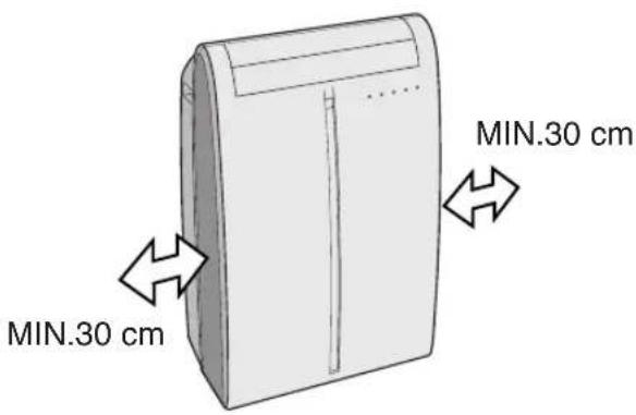
- Never place any obstacles around the air inlet or outlet of the unit.
- Allow at least 30 cm of space from the wall for ef cient air-conditioning.
INCLUDED
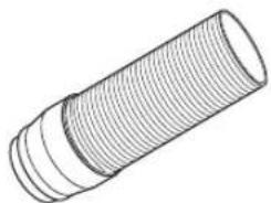
Exhaust hose (1)

natural_image
Line drawing of a cylindrical mechanical part with threaded ends (no text or symbols)
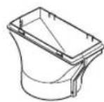
Window exhaust adapter (1)

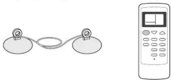
Suction disk (1) Remote control (1)

natural_image
Simple line drawing of two circular objects connected by a rope, no text or symbols present

Insect guard net (1) Hose clamp (1)
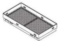

Battery (2) (AAA.R03)

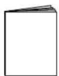
Manual (1)
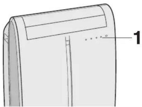
FRONT VIEW

① Air Outlet
② Vertical louvers
③ Horizontal louvers
④ PLASMACLUSTER Lamp (blue)
⑤ Remote control signal receiver window
⑥ AUX. Button
⑦ OPERATION Lamp (red ☐)
⑧ TIMER Lamp (orange ⏻)
⑨ TURBO COOL Lamp (green 📋)
⑩ Air inlet
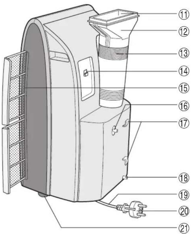
REAR VIEW
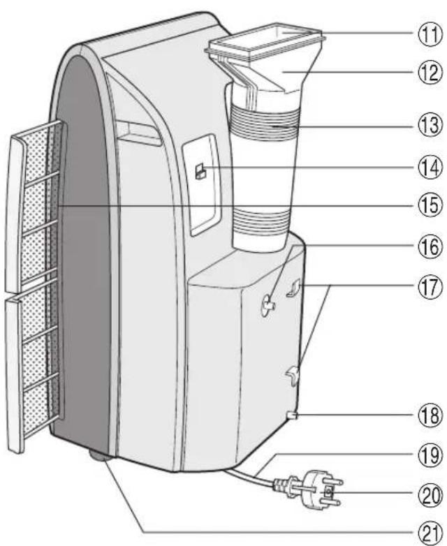
⑪ Exhaust air outlet
⑫ Exhaust adapter
⑬ Exhaust hose
⑭ Remote control hook
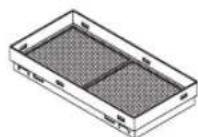
⑮ Air filters
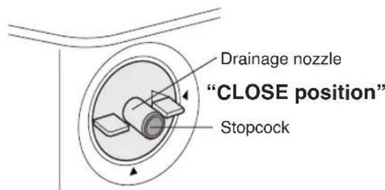
⑯ Drainage nozzle and stopcock
⑰ Power supply cord hooks
⑱ Drainpipe nozzle and stopcock
⑲ Power supply cord
⑳ Power plug
②1 Casters (4)
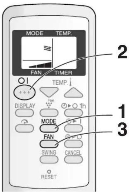
REMOTE CONTROL
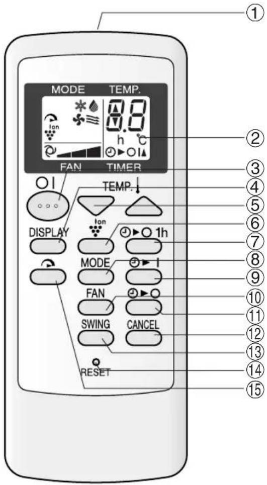
① Transmitter
② Display
③ ON/OFF Button
④ DISPLAY Button
⑤ TEMPERATURE Button
⑥ PLASMACLUSTER Button
⑦ 1 hr OFF Button
⑧ MODE Button
⑨ ON TIMER Button
⑩ FAN Button
⑪ OFF TIMER Button
⑫ CANCEL Button
⑬ SWING Button
⑭ RESET Button
⑮ TURBO COOL Button
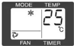
REMOTE CONTROL DISPLAY

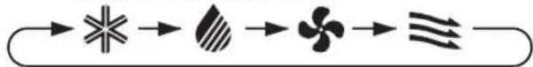
⑯ MODE SYMBOLS
* : COOL : DEHUMIDIFICATION
: FAN : VENTILATION
⑰ TURBO COOL SYMBOL
⑱ PLASMACLUSTER SYMBOL
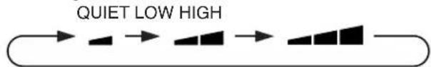
⑲ FAN SPEED SYMBOLS
: AUTO : Manual setting
⑳ TEMPERATURE AND TIMER COUNT DOWN INDICATOR
②1 TRANSMITTING SYMBOL
⑳ ON TIMER/OFF TIMER SYMBOL
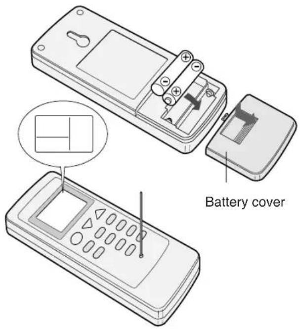
LOADING BATTERIES Use two AAA (R03) batteries.
1 Remove the battery cover at the back of the remote control.
2 Insert batteries into the compartment, making sure the and polarities are correctly aligned.
- Lines will appear on the display when batteries are properly installed.
3 Reattach the battery cover.
4 Press the RESET button using a thin pointed implement.
NOTES:
• The battery should last approximately one year under normal use.
- When replacing the batteries, always change both batteries at the same time, and make sure they are the same type.
- If the remote control does not operate normally after replacing the batteries, press the RESET button using a thin pointed implement.
- If you will not be using the unit for a prolonged period, remove the batteries from the remote control.
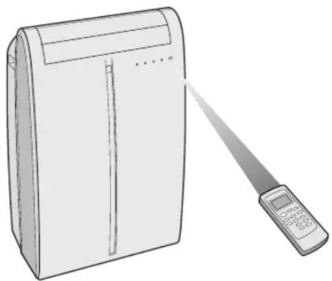
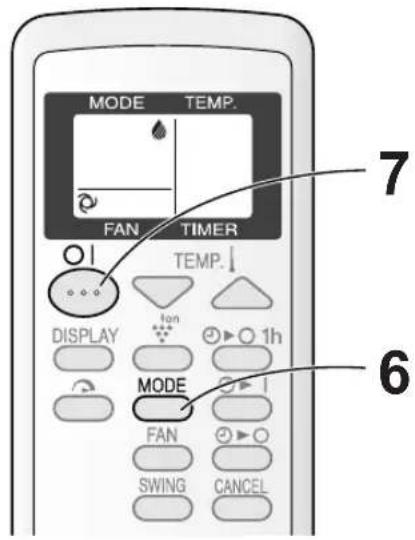
HOW TO USE THE REMOTE CONTROL
Point the remote control towards the units signal receiver window and press the desired button. A beep will sound when the unit receives the signal.
- Make sure nothing, such as curtains, blocks the signal receiver window.
- The remote control operates up to 7 meters away.
natural_image
Line drawing of a portable air conditioner with a handheld remote control (no text or symbols)
CAUTION
- Do not expose the signal receiver window to direct sunlight. This may adversely affect its operation. If necessary, close the curtains to block out the sunlight.
- Use of a fluorescent lamp in the same room may interfere with transmission of the signal.
- The unit may be affected by signals emitted from other remote controllers for televisions, VCRs or other equipment used in the same room.
- Do not leave the remote control exposed to direct sunlight or near a heater. Protect the remote control from moisture and shock which can discolor or damage it.
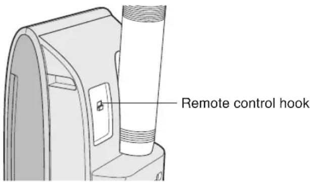
To prevent the remote control from being misplaced, hook it to the unit when not in use.
When attached, to remove the remote control from the unit, lift the remote control up slightly and pull it out.
INSTALLATION AND REMOVAL OF EXHAUST HOSE
The exhaust hose must be installed or removed in accordance with the usage mode.
| Mode Exhaust hose | |
| COOL, FAN, VENTILATION Install |
| DEHUMIDIFICATION Remove | |
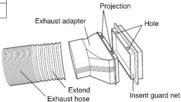
Installation of the exhaust hose
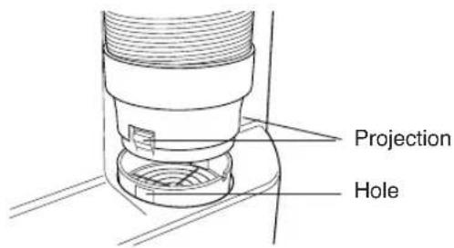
1 Attach the insect guard net to the exhaust adapter.
Push the insect guard net firmly to ensure that four projections on the exhaust adapter fit into the four holes on it.
2 Attach the Exhaust adapter to the exhaust hose.
Extend one end of the exhaust hose and insert it into the Exhaust adapter, and turn it (approx. three times) until it stops.
Make sure they are securely attached afterwards.
3 Attach the exhaust hose adapter to the unit.
Insert the two projections on the exhaust hose adapter into the two holes on the unit, and firmly attach them to each other.
4 Lead the exhaust hose outdoors
Suction disk may be used to keep window or door closed.

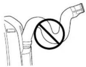
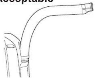
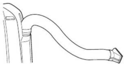
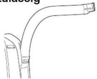
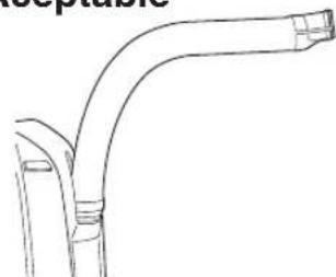
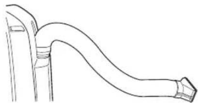
The exhaust hose should be as short as possible for operational efficiency; however, it must not be twisted or bent.
Unacceptable
natural_image
Diagram of a pipe with a circular symbol indicating no pollution or prohibition (no text or labels present)
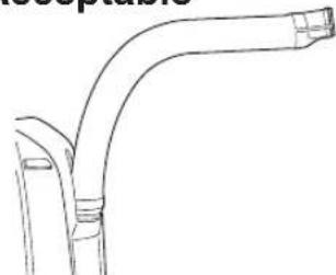
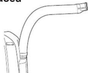
Acceptable
natural_image
Line drawing of a curved pipe or duct with a flanged end (no text or symbols)
Acceptable
natural_image
Line drawing of a curved pipe or duct with flanged ends, no text or symbols present
Removal of the exhaust hose
1 Remove the exhaust hose adapter from the unit.
Lift up and remove the exhaust hose adapter from the unit by pushing down on the two projections.

Install the exhaust hose (See Page 8), turn the drainage nozzle to the CLOSE position, and check the drainage nozzle is covered with the stopcock.
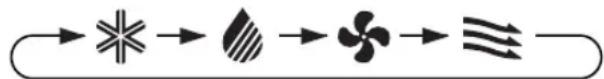
1 Press the MODE button to select COOL mode.

flowchart
graph LR
    A["Star"] --> B["Shade"]
    B --> C["Flores"]
    C --> D["Leaf-like Shape"]
    D --> E["Tree"]
2 Press the ON/OFF button to start operation.
- The red OPERATION lamp (☐) on the unit will light.
3 Press the TEMPERATURE button to set the desired temperature.
• The temperature can be set within the range of 18^ C to 32^ C.

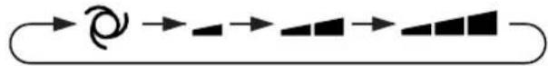
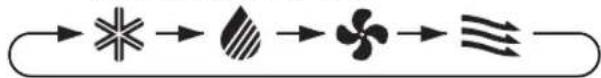
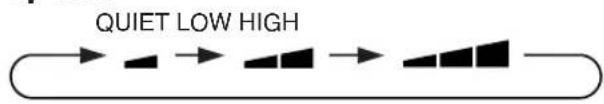
4 Press the FAN button to set the desired fan speed.
AUTO QUIET LOW HIGH
flowchart
graph LR
    A[" "] --> B[" "]
    B --> C[" "]
    C --> D[" "]
    D --> E[" "]
TO TURN OFF
Press the ON/OFF button again.
- The red OPERATION lamp (☐) on the unit will turn off.
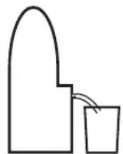
In this mode, the air conditioner dehumidifies the room.

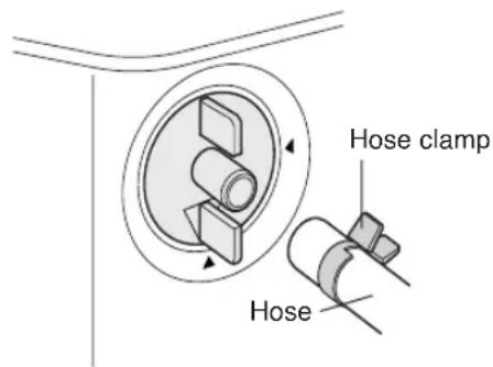
"OPEN position"

1 Remove the exhaust hose (See Page 8)
2 Turn the drainage nozzle to the OPEN position.
3 Pull the stopcock out from the drainage nozzle.
- When the stopcock is removed, a small amount of water may be discharged from the drainage nozzle.
- Always perform this procedure with the unit turned off. Drain water will spout out if attempted during operation.
4 Insert the hose clamp into a standard commercially-available hose (12.7 mm inner diameter, 16.7 mm outer diameter)
5 Attach the hose to the drainage nozzle, and secure it with the hose clamp.
- Depending on room condition, approximately 28 liters of water per day (24 hours) will be dehumidified.
Prepare some kind of bucket of appropriate size to collect drain water, or take some appropriate measure to drain the water outside of the room, so that drain water will not overflow or soak your room.
- Set the hose sloping downwards for easier drainage. Moreover, do not bend the hose at any point, nor allow the end to be submerged in water.
6 Press the MODE button to select DEHU-MIDIFICATION mode.
COOL DEHUM FAN VENT
flowchart
graph LR
    A["Start"] --> B["Star"]
    B --> C["Leaf"]
    C --> D["Flower"]
    D --> E["Trigram"]
7 Press the ON/OFF button to start operation.
- The red OPERATION lamp ( ☐ on the unit will light.
• The temperature cannot be set.
- The fan speed is preset to AUTO and cannot be changed.
TO TURN OFF
- The red OPERATION lamp ( ☐) on the unit will turn off.
CAUTION
The unit generates heat during dehumidification mode and the room temperature will rise. Install the exhaust hose if you do not want the room temperature to rise. This will help to slightly drop the room temperature, but dehumidification performance will become less effective than when operating without the exhaust hose.
In this mode, the air conditioner simply circulates the air without cooling it.
Install the exhaust hose (See Page 8), turn the drainage nozzle to the CLOSE position, and check the drainage nozzle is covered with the stopcock.

1 Press the MODE button to select FAN mode.
COOL DEHUM FAN VENT
flowchart
graph LR
    A["Start"] --> B["Star"]
    B --> C["Leaf"]
    C --> D["Flower"]
    D --> E["Arrow"]
2 Press the ON/OFF button to start operation.
- The red OPERATION lamp ( ☐ on the unit will light.
- The temperature cannot be set.
3 Press the FAN button to set the desired fan speed.
flowchart
graph LR
    A["Start"] --> B["Step 1"]
    B --> C["Step 2"]
    C --> D["Step 3"]
    D --> E["Step 4"]
TO TURN OFF
Press the ON/OFF button again.
- The red OPERATION lamp ( ☐ on the unit will turn off.
VENTILATION MODE
In this mode, the air conditioner ventilates the air to outdoors.
Install the exhaust hose (See Page 8), turn the drainage nozzle to the CLOSE position, and check the drainage nozzle is covered with the stopcock.
1 Press the MODE button to select VENT mode.
COOL DEHUM FAN VENT
flowchart
graph LR
    A["Start"] --> B["Star"]
    B --> C["Leaf"]
    C --> D["Flower"]
    D --> E["Three Triangle Shape"]
2 Press the ON/OFF button to start operation.
- The red OPERATION lamp ( ☐ on the unit will light.
- The temperature cannot be set.
3 Press the FAN button to set the desired fan speed.
- Although the louvers are closed and no air blows out into the room, the external ventilation fan speed changes.
flowchart
graph LR
    A["Start"] --> B["Next Step"]
    B --> C["Next Step"]
    C --> D["Next Step"]
TO TURN OFF
Press the ON/OFF button again.
- The red OPERATION lamp ( ☐ on the unit will turn off.
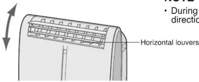
UP/DOWN AIR FLOW DIRECTION

1 Press the SWING button on the remote control.
• The horizontal louvers will swing continuously.
2 Press the SWING button again when the horizontal louvers are at the desired position.
• The horizontal louvers will stop moving.
- The adjusted position will be memorized and the same position will be set automatically when operated the next time.
NOTE
- During VENTILATION mode, UP/DOWN air flow direction cannot be changed.
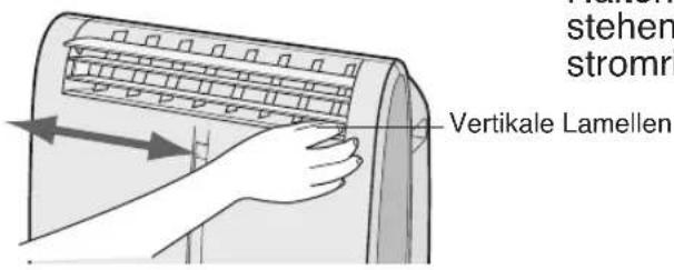
LEFT/RIGHT AIR FLOW DIRECTION

Hold the vertical louver as shown in the diagram and adjust the air flow direction.
CAUTION
Never attempt to adjust the horizontal louvers manually.
- Manual adjustment of the horizontal louvers can cause the unit to malfunction when the remote control is used for adjustment.
- When the horizontal louvers are positioned at the lowest position in the COOL or DEHUMIDIFICATION mode for an extended period of time, condensation may result.
Do not adjust the vertical louvers to the extreme left or right in the COOL mode with the fan speed set to "QUIET (☐)" for an extended period of time.
Condensation may form on the louvers.
In this operation, the air conditioner fan works at extra high speed with a setting temperature of 15^ C.
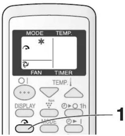
• The remote control will display “
• The temperature display will go off.
- The green TURBO COOL lamp ( ) on the unit will light.
TO CANCEL
- TURBO COOL operation is also cancelled when the mode is changed, or when the unit is turned off.
- The green TURBO COOL lamp ( ) on the unit will turn off.
NOTES:
- You cannot set the temperature or fan speed during TURBO COOL operation.
- The fan returns to the HIGH speed setting after the unit has run for 30 minutes in TURBO COOL mode.
- The extra high fan speed may automatically slow down to protect the unit.
ONE-HOUR OFF TIMER
When the ONE-HOUR OFF TIMER is set, the unit will automatically turn off after one hour.
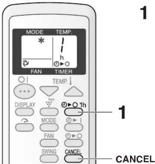
• The remote control displays “ /”h Ⓑ▶ O
• The orange TIMER lamp ( ) on the unit will light.
• The unit will stop operating after one hour.
TO CANCEL
- The orange TIMER lamp ( Ⓓ on the unit will turn off.
Alternatively, turn the unit off by pressing the ON/OFF button.
- The red OPERATION lamp (☐) and the orange TIMER lamp (☐) on the unit will turn off.
NOTES:
- The ONE-HOUR OFF TIMER operation has priority over ON TIMER and OFF TIMER operations.
- If the ONE-HOUR OFF TIMER is set while the unit is not operating, the unit will operate for an hour at the formerly set condition.
- If you wish to operate the unit for another hour before the ONE-HOUR OFF TIMER is activated, press the 1hr OFF TIMER button again during operation.
OFF TIMER
The unit will turn off automatically according to your setting.
Timer duration can be set from a minimum of half an hour (30 minutes) to a maximum of 12 hours.
Up to 9.5 hours, you can set in half-hour (30-minutes) increments and from 10 to 12 hours, in 1-hour increments.

Display shown when you set the unit to turn off 2.5 hours later.
Point the remote control at the signal receiver window on the unit.
- The time setting will change as you press the button as follows.
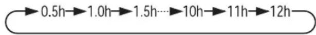
flowchart
graph LR
    A["0.5h"] --> B["1.0h"]
    B --> C["1.5h"]
    C --> D["..."]
    D --> E["10h"]
    E --> F["11h"]
    F --> G["12h"]
Hold the button down to speed through the settings.
- The orange TIMER lamp ( ☑ on the unit will light.
• The unit will emit a beep when it receives the signal.
- The time setting will count down to show the remaining time.
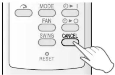
TO CANCEL TIMER
- The orange TIMER lamp on the unit will turn off.
- The latest time setting will be memorized and will appear on the remote control display the next time you set the OFF TIMER or ON TIMER.
- The OFF TIMER and ON TIMER can not be set together.
Only the most recent TIMER setting will be valid.
- While the ONE-HOUR OFF TIMER is set, the OFF TIMER and ON TIMER is settings are unavailable.
- If the ONE-HOUR OFF TIMER is set while the OFF TIMER or ON TIMER activated, the ON TIMER or OFF TIMER setting will be cancelled.
- If a power failure occurs while the OFF TIMER or ON TIMER is set, the TIMER setting will be cancelled and will not be retrieved even after the power is restored.
ON TIMER
The unit will turn on automatically according to your setting.
Timer duration can be set from a minimum of half an hour (30 minutes) to a maximum of 12 hours.
Up to 9.5 hours, you can set in half-hour (30-minute) increments and from 10 to 12 hours, in 1-hour increments.

Display shown when you set the unit to turn on 6.5 hours later.
Point the remote control at the signal receiver window on the unit.
- The time setting will change as you press the button as follows.

flowchart
graph LR
    A["0.5h"] --> B["1.0h"]
    B --> C["1.5h"]
    C --> D["..."]
    D --> E["10h"]
    E --> F["11h"]
    F --> G["12h"]
Hold the button down to speed through the settings.
• The orange TIMER lamp ( ) on the unit will light.
• The unit will emit a beep when it receives the signal.
- The time setting will count down to show the remaining time.
Select the mode, temperature, fan speed setting and PLASMACLUSTER operation as desired.
- When the temperature is set with the ON TIMER, the temperature will show in the display for 5 seconds and then return to the time display.
- If you do not change the setting, the unit will operate using the most recent setting.
TO CANCEL TIMER
• The orange TIMER lamp on the unit will turn off.
PLASMACLUSTER OPERATION
The Plasmacluster ion generator inside the air conditioner will release positive and negative Plasmacluster ions into the room. Approximately the same numbers of positive and negative ions released into the air will reduce some airborne mold.

• The remote control will display “
- The blue PLASMACLUSTER lamp on the unit will light.

TO CANCEL
• The PLASMACLUSTER lamp on the unit will turn off.
NOTES:
- Use of the PLASMACLUSTER function will be memorized and it will be activated the next time you turn on the air conditioner.
- To turn off the PLASMACLUSTER Lamp, press the DISPLAY button.
- PLASMACLUSTER operation cannot be set during VENTILATION mode.
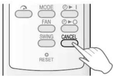
AUXILIARY MODE
Use this mode when the remote control is not available.
natural_image
Technical line drawing of a mechanical component with labeled part '1' (no text or symbols beyond label)
- The red OPERATION lamp ( ☐ on the unit will light and the unit will start operating in COOL mode.
• The fan speed is set to AUTO.
- The temperature setting is automatically set according to the room temperature.
TO TURN OFF
- The red OPERATION lamp ( ☑ on the unit will turn off.
NOTES:
- If the AUX. button is pressed during normal operation, the unit will turn off.
- Upon starting AUXILIARY operation, the drainage pump inside the unit runs for about a minute, which may produce an audible gurgling sound.
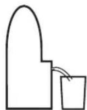
Prepare for drainage and drain out water within the unit in the following cases.
If the unit stops operating and the TIMER ( Ⓞ, OPERATION ( ) and TURBO COOL ( ) lamps are blinking. (This indicates that the water tank inside the unit is full.)
1 Make sure to turn the unit off.
2 Turn the drainage nozzle to the OPEN position.
3 Pull the stopcock out from the drainage nozzle.
- When the stopcock is removed, a small amount of water may be discharged from the drainage nozzle.
4 Insert the hose clamp into a standard commercially available hose (12.7 mm inner diameter, 16.7 mm outer diameter).
5 Attach the hose to the drainage nozzle, and secure it with the hose clamp.
- Prepare for draining, as drain water will come out through the hose during operation.
6 Press the AUX. button on the unit twice.
- The water will drain out through the drainage hose. Mximum amount of water that may be drained out is approximately 2 liters.
- The OPERATION, TIMER and TURBO COOL lamps will be blinking.
7 When drainage water stops running out from the hose, turn the unit off by pressing AUX. button.
• This would take about one minute.
8 Remove the hose from the drainage nozzle, and replace the stopcock.
- Keep the hose clamp in case of re-used.
9 Turn the drainage nozzle to the CLOSE position.

"OPEN position"

Whenever the unit is moved (to prevent water within the unit from spilling). When the unit is not used for a long time.
1 Carry out the above procedures from 1 to 5.
2 Press the AUX. button on the unit.
- The water will drain out through the drainage hose.
- Maximum amount of water that may be drained out is approximately 2 liters.
• The OPERATION lamps will light.
3 When drainage water stops running out from the hose, turn the unit off by pressing AUX. button.
• This would take about one minute.
4 Remove the hose from the drainage nozzle, and replace the stopcock.
- Keep the hose clamp in case of re-used.
5 Turn the drainage nozzle to the CLOSE position.
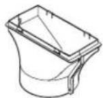
6 Remove the stopcock from the drainpipe nozzle, and completely drain any water within the unit.
- Always prepare a receptacle to collect the water before draining. Maximum amount of water that may be drained out is approximately 0.2 liters.
7 Replace the stopcock to the drainpipe nozzle.

Drainpipe nozzle
Be sure to disconnect the power from the wall socket before performing any maintenance.
CLEANING THE FILTERS
If the filter is clogged with dust, the airflow will be reduced, resulting in poor cooling performance. The filter should be cleaned every two weeks.

1 REMOVE THE FILTERS
- Gently pull the Iter handle to the right and slide the Iter out of the unit.
2 CLEAN THE FILTERS
- Use a vacuum cleaner to remove any dust. If the filters are very dirty, wash them with detergent and rinse carefully with clean water. Dry the Iters in the shade before reinstalling them.
3 REINSTALL THE FILTERS
- Hold the filter handle and gently push the filter back into place.
Never operate the unit without the Iter. Doing so may result in serious damage to the unit.
CLEANING THE UNIT AND THE REMOTE CONTROL
Wipe them with a soft, dry cloth or with a cloth moistened with a mild soap. Carefully remove any residue by wiping with a damp cloth and dry completely.
Avoid splashing water onto the unit. Water can dangerously damage the electrical insulation. Never use harsh chemicals or abrasive cleaners on any part of the unit. To avoid damaging the unit, do not use hot water (50°C or hotter) when cleaning.
CLEANING THE INSECT GUARD NET
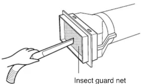
The cooling performance may be reduced or stop completely if the insect guard net becomes clogged with dust.
Clean the insect guard net with a vacuum cleaner or suchlike.
MAINTENANCE AFTER AIR CONDITIONER SEASON
1 Perform drainage to drain out water within the unit. (See Page 17 "When the unit is not used for a long time").
2 Operate the unit the FAN or VENTILATION mode for about half a day to thoroughly dry inside the unit.
3 Clean the filters, then reinstall them.
BEFORE CALLING FOR SERVICE
If the unit appears to be malfunctioning, check the following points before calling for a service.
AIR CONDITIONER DOES NOT OPERATE AT ALL
- Is the unit plugged in or is the plug loose?
- Has the fuse blown or is the circuit breaker tripped?
- Did you restart the unit within 3 minutes of a power failure?
If the power was off for less than 3 minutes when, you restarted the air conditioner, a protective device may cause the compressor to shut off, preventing cooling for about 5 minutes.
- Are the OPERATION (☐), TIMER (☐) and TURBO COOL (☐) lamps blinking?
The water tank inside the unit is full. It must be drained. (See page 17)
AIR CONDITIONER DOES NOT COOL PROPERLY
- Is it set to FAN, DEHUMIDIFICATION or VENTILATION mode?
Cooling does not take place in these modes. Change the MODE setting.
- Are the Iters clogged with dust?
Clean and replace the Iters.
• Is the cooling coil frozen?
No air will blow out if the cooling coil is frozen.
Run the air conditioner in FAN mode with the fan speed set to "HIGH" until all ice dissipates.
• Is the temperature set properly?
• Is the window exposed to direct sunlight?
Close the curtains or blinds to minimize solar energy heating the room.
• Is the exhaust hose too long?
For efficient operation, make the hose as short as possible. The exhaust hose must not be twisted or bent.
SOUNDS
- The unit may seem rather loud for the first 2 to 3 minutes when the unit is turned on. This is the sound of the compressor starting-up and is perfectly normal.
- A soft, swishing noise can be heard immediately after the unit is turned on or off, and also during operation. This is the sound of the refrigerant owing inside the unit.
- A low buzzing noise is emitted when the unit is generating Plasmacluster ions.
- This air conditioner evaporates water condensed during cooling operation within the unit through the exhaust air outlet. Although water owing sound way be heard, this is normal.
- An audible gurgling sound may be heard for about a minute upon starting AUXILIARY mode. This is sound of running drainage pump inside the unit.
- An audible gurgling sound may be heard when the unit is operated on a gently sloping oor. Place the unit on a level oor.
TIMER DOES NOT WORK PROPERLY
- If a power failure occurs while the TIMER is set, the TIMER setting will be cancelled and will not be retrieved even after the power is restored. This is normal for this unit.
THE UNIT FAILS TO REACT TO THE REMOTE CONTROL SIGNAL
- Check the batteries in the remote control. Replace if necessary.
- Try to send the signal again with the remote control pointed directly at the unit's signal receiver window.
- Check whether the remote control batteries are installed with the polarities properly aligned.
THE DISCHARGED AIR HAS AN ODOR
- This is the smell of ozone generated from the Plasmacluster Ion generator. The ozone concentration is very small, posing no adverse effect on your health. The ozone discharged into the air rapidly decomposes, and its density in the room will not increase.
natural_image
Symbol of a trash bin crossed with a diagonal line, no text or numbers present
LIEFERUMFANG
Abluftschlauch (1) Fensterabluft-Adapter (1) Insektenschutzgitter (1) Schlauchschelle (1)

natural_image
Line drawing of a cylindrical mechanical part with threaded ends (no text or symbols)


⑱ PLASMACLUSTER-SYMBOL
⑲ LÜFTERGESCHWINDIGKEITS-SYMBOLE
natural_image
Line drawing of a portable air conditioner with a handheld remote control (no text or symbols)
VORSICHT
natural_image
Diagram of a pipe with a circular symbol indicating no pollution or prohibition (no text or labels)
Zulässig
natural_image
Line drawing of a curved pipe or duct with flanged ends, no text or symbols present
Zulässig

natural_image
Line drawing of a curved pipe or duct with flanged ends, no text or symbols present
LUFTSTROM NACH LINKS/RECHTS
PLASMACLUSTER-BETRIEB
natural_image
Technical line drawing of a mechanical component with labeled part '1' (no text or symbols beyond label)
natural_image
Symbol of a trash bin crossed out by two crossed lines, with a solid black rectangle below (no text or labels)
PIECES FOURNIES
natural_image
Technical line drawing of a cylindrical mechanical component with threaded ends (no text or symbols)
Ventouses (1)


⑱SYMBOLE DU PLASMACLUSTER
⑲SYMBOLES DE VITESSE DU VENTILATEUR

natural_image
Line drawing of a portable air conditioner with a handheld remote control (no text or symbols)
ATTENTION
natural_image
Diagram of a pipe with a circular symbol indicating no pollution or prohibition (no text or labels)
Acceptable
natural_image
Line drawing of a bent pipe or duct with flanged ends (no text or symbols)
Acceptable

natural_image
Line drawing of a curved pipe or duct with a flanged end (no text or symbols)
natural_image
Technical line drawing of a mechanical component with labeled part '1' (no text or symbols beyond label)
IN DOTAZIONE
natural_image
Simple line drawing of a cylindrical object with concentric grooves (no text or symbols)
⑱ SIMBOLO PLASMACLUSTER
⑲ SIMBOLI DI VELOCITÀ DEL VENTILATORE
natural_image
Line drawing of a portable air conditioner with a handheld remote control (no text or symbols)
PRECAUZIONI
natural_image
Diagram of a pipe with a circular symbol indicating no pollution or prohibition (no text or labels present)
Accettabile

natural_image
Line drawing of a bent pipe or duct with flanged ends (no text or symbols)
Accettabile

natural_image
Line drawing of a curved pipe or duct with flanged ends, no text or symbols present
flowchart
graph LR
    A["→"] --> B["→"]
    B --> C["→"]
    C --> D["→"]
PER SPEGNERE
natural_image
Technical line drawing of a garment sleeve with measurement annotations (no text or symbols)
natural_image
Symbol of a trash bin crossed with no visible text or labels
natural_image
Simple line drawing of a cylindrical object with internal grooves (no text or symbols)
natural_image
Line drawing of a portable air conditioner with a handheld remote control (no text or symbols)
PRECAUCIÓN
natural_image
Diagram of a pipe with a circular symbol indicating no pollution or prohibition (no text or labels)
Acceptable
natural_image
Line drawing of a bent pipe or duct with flanged ends (no text or symbols)
Acceptable

natural_image
Line drawing of a curved pipe or duct with flanged ends, no text or symbols present
natural_image
Technical diagram of a mechanical component with concentric circles and labeled parts (no readable text or symbols)
natural_image
Illustration of a hand pressing down on a curved air conditioner cover (no text or symbols)
natural_image
Technical line drawing of a folded garment or fabric component with no visible text or symbols
natural_image
Symbol of a trash bin crossed with no text or numbers, representing waste sorting or disposal (no text present)
WAARSCHUWINGEN MET BETREKKING TOT HET NETSNOER
ACCESSOIRES
Uitlaatslang (1)
natural_image
Line drawing of a cylindrical mechanical part with threaded ends (no text or symbols)
Uitlaatstuk (1)
Zuignappen (1) Afstandsbediening (1)
natural_image
Simple line drawing of a two-circle device connected to a digital control panel (no text or symbols)
Insectengaas (1) Slangenklem (1)

⑱ PLASMACLUSTERSYMBOOL
⑲ SYMBOLEN VOOR DE VENTILATORSNELHEID

natural_image
Line drawing of a portable air conditioner unit with a handheld device emitting a laser beam (no text or symbols)
LET OP
natural_image
Diagram of a pipe with a circular symbol indicating no pollution or prohibition (no text or labels)
Goed
natural_image
Line drawing of a bent pipe or tube with a flanged end (no text or symbols)
Goed

natural_image
Line drawing of a curved pipe or duct with flanged ends, no text or symbols present
flowchart
graph LR
    A["ZACHT"] --> B["LAAG HOOG"]
    B --> C["..."]
UITSCHAKELEN
flowchart
graph LR
    A["ZACHT"] --> B["HOOG"]
    B --> C["HOOG"]
    C --> D["HOOG"]
UITSCHAKELEN
natural_image
Technical line drawing of a curved air conditioner unit with ventilation grilles and airflow direction arrow (no text or symbols)
natural_image
Illustration of a hand pressing down on a curved air conditioner cover (no text or symbols)
1 Druk op de ÉÉN-UURS TIMER-toets.
1 Druk op de PLASMACLUSTER-toets terwijl de airconditioner is ingeschakeld.
natural_image
Technical line drawing of a mechanical component with labeled part '1' (no text or symbols beyond label)
natural_image
Symbol of a trash bin crossed with a diagonal line, no text or labels present
ELEMENTY ZESTAWU
natural_image
Technical line drawing of a cylindrical mechanical part with threaded ends (no text or symbols)
WIDOK Z TYŁU
natural_image
Line drawing of a portable air conditioner unit with a handheld remote control (no text or symbols)
OSTRZEŻENIE
natural_image
Diagram of a pipe with a circular symbol indicating no pollution or prohibition (no text or labels present)
Prawidłowo

natural_image
Line drawing of a bent pipe or duct with a flanged end (no text or symbols)
Prawidłowo
natural_image
Line drawing of a curved pipe or tube with a flanged end, no text or symbols present
natural_image
Simple line drawing of a curved structure and a bucket with arrows indicating flow (no text or symbols)
flowchart
graph LR
    A["QIET"] --> B["Low"]
    B --> C["HIGH"]
WYŁĄCZANIE KLIMATYZATORA
flowchart
graph LR
    A["QIET"] --> B["LOW"]
    B --> C["HIGH"]
WYŁĄCZANIE KLIMATYZATORA
natural_image
Technical line drawing of a mechanical component with labeled part '1' (no text or symbols beyond label)
KLIMATYZATOR NIE REAGUJE NA SYGNAŁ PILOTA