CRM1029 FCO-1524 - Compressor Ferm - Free user manual and instructions
Find the device manual for free CRM1029 FCO-1524 Ferm in PDF.

User questions about CRM1029 FCO-1524 Ferm
0 question about this device. Answer the ones you know or ask your own.
Ask a new question about this device
Download the instructions for your Compressor in PDF format for free! Find your manual CRM1029 FCO-1524 - Ferm and take your electronic device back in hand. On this page are published all the documents necessary for the use of your device. CRM1029 FCO-1524 by Ferm.
USER MANUAL CRM1029 FCO-1524 Ferm
natural_image
Black FERM air compressor with blue wheels and control panel (no visible text or symbols on body)GB USERS MANUAL 05
D GEBRAUCHSANWEISUNG 13
NL GEBRUIKSAANWIJZING 22
F MODE D'EMPLOI 31
E MANUALDE INSTRUCCIONES 39
P MANUALDE INSTRUÇÕES 47
I MANUALE UTILIZZATI 55
S BRUKSANVISNING 63
FIN KÄYTTÖOHJE 71
N BRUKSANVISNING 79
DK BRUGERVEJLEDNING 87
CE
www.ferm.com

text_image
1 2 3 4 5 6 7 8 9 10 11 FERM Fig. A02 Ferm Ferm 99
text_image
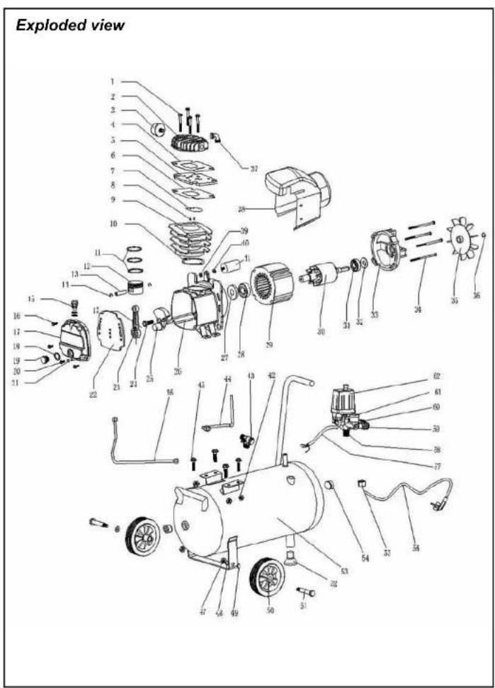
Exploded view 1 2 3 4 5 6 7 8 9 10 11 12 13 14 15 16 17 18 19 20 21 22 23 24 25 26 27 28 29 30 31 32 33 34 35 36 37 38 39 40 41 42 43 44 45 46 47 48 49 50 51 52 53 54 55 56 57 58 59 60 61 62Spare parts list
No. Description Position
| 400982 Air filter 3 | ||
| 400983 Gasket set 4, 6, 10 | ||
| 400984 Valve plate complete 5, 7,8 | ||
| 400985 Oil fill cap 15 | ||
| 400986 Carter cover with sealing 17, 22 | ||
| 400987 Oil lever 18, 19 | ||
| 806204 Bearing 6204 28 | ||
| 806202 Bearing 6202 31 | ||
| 400989 Fan | 35 | |
| 800035 Capacitor | 41 | |
| 400990 Non return valve | 43 | |
| 400991 Release pipe | 44 | |
| 400992 Pressing pipe | 46 | |
| 400993 Wheel mounting set | 47, 48, 49, 51 | |
| 400994 Wheel | 50 | |
| 400995 Rubber foot | 52 | |
| 400996 Nut for autoswitch | 55 | |
| 205915 Safty valve | 58 | |
| 400997 Pressure regulator | 59 | |
| CRA1005 | Pressure gauge | 60 |
| CRA1002 | Autostop switch | 62 |
natural_image
Technical line drawing of two mechanical components with wheels and a wheelbase (no text or symbols)

natural_image
Three technical illustrations of industrial equipment: a gas cylinder, a windmill with rotor, and a forklift (no text or symbols present)

text_image
7 8 9

natural_image
Two technical diagrams showing mechanical components and warning symbols (no readable text or labels)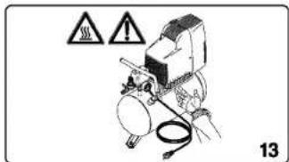
text_image
13
Ferm 0398 Ferm
natural_image
Exploded view diagram of a mechanical assembly with gears and housing (no text or labels)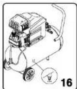

COMPRESSOR OIL-BASED
The numbers in the following text correspond with the pitcures at page 2 - 3.

Carefully read this manual before using the machine. Make sure that you know how the machine functions and how to operate it. Maintain the machine in accordance with the instructions to make sure it functions properly. Keep this manual and the enclosed documentation with the machine.
Contents
- Machine details
- Safety instructions
- Use
- Faults
- Maintenance
1. MACHINE DETAILS
Technical specifications
| Voltage 230 V~ | |
| Frequency 50 Hz | |
| Capacity 1.5 hp (1100 W) | |
| Idling speed 2850/min | |
| IPClass IP 20 | |
| Tank contents 24litre | |
| Air intake | 160 l/min |
| Max. outlet pressure | 8.0 Bar |
| Weight | 24.0 kg |
| Sound power level | 91.0 dB (A) |
The value of the noise level may rise from 1 to 10 dB(A) as a function of the environment in which the compressor will be installed.
Product information
Fig. A
1 Cover
- Handle
- Switch
- Automatic stop
- Pressure regulator
- Quick coupler (outlet)
- Pressure gauge (pressure regulator)
- Pressure gauge (tank)
- Safety valve
- Pressure pipe
Ferm 05
- Air filter
- Oil cap
- Sump
- Drain cock
2.SAFETYINSTRUCTIONS
Explanation of symbols
The following symbols are used in these instructions for use:


Read the instructions.
In accordance with essential applicable safety standards of European directives.
Denotes risk of personal injury, loss of life or damage to the tool in case of non-observance of the instructions in this manual.
Risk of electric shock.
Remove the plug from the mains
Attention: the compressor could start automatically in case of a black-out and subsequent reset
Caution: the compressor contains some parts with might reach high temperatures
Wear ear protection.
Sound power level
Faulty and/or discarded electrical or electronic apparatus have to be collected at the appropriate recycling locations.
Special safety instructions
- Warning! The compressor may only be used in suitable rooms (with good ventilation and an ambient temperature from +5^ to +40^ ).
- It is recommended to use the compressor with a maximum operation of 70% in one hour under full load, to allow for proper operation of the product over time.
CE KONFORMITETSERKLÆRING (DK)
98/37/IEC, 73/23/EEC, 89/336/IEEC, 87/404/IEEC, 2000/14/IEC, 2002/95/IEC, 2002/96/IEC
Målt lydtrykniveau; Lwa = 91.1 dB(A)
Garanteret lydtrykniveau; Lwa = 91 dB(A)
2000/14/EC: Det garanterede lydtrykniveau er lavere end 96 dB(A). Procedure for overholdelsesvurdering ifølge Anneks VI.
Bemyndiget organ: TUV product service GmbH
Bemyndiget organs identifikationsnummer: 70.403.06.078.13
fran 01-08-2006
ZWOLLE NL
CEO Ferm BV Quality Manager Ferm Global
- Check that the tank is fully decompressed before connections with the tank are unscrewed.
- It is prohibited to make holes in, or welds to, or purposely to distort the compressed air tank.
- Do not perform any actions on the compressor without first having taken the plug out of the plug socket.
- Do not aim water jets or jets of flammable liquids at the compressor.
- Do not place flammable objects near the compressor.
- Switch the pressure regulator to the "0" position (OFF = uit) during dwell time.
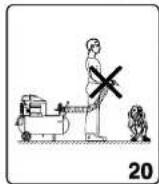
- Never aim the air jet at persons or animals (fig. 20).
- Do not transport the compressor with the tank pressurised.
- N.B.: some parts of the compressor such as the head and the feed-through pipes may reach high temperatures. Do not touch these parts to avoid burns (fig. 12-13).
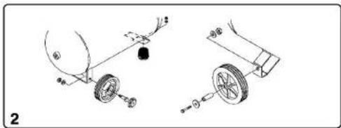
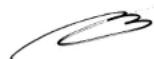
- Transport the compressor by lifting it or by using the special grips or handles (fig. 5-6).
- Children and animals should be kept far away from the area of operation of the machine.
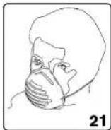
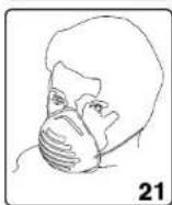
- If you use the compressor to spray paint:
a) Do not work in enclosed spaces or near naked flames.
b) Make sure that the environment in which you will be working has dedicated ventilation.
c) Protect your nose and mouth with a dedicated mask (fig. 21). - Do not use the compressor when the electrical cable or the plug is damaged, and instruct an authorised Support Service to replace them with an original part.
- When the compressor is placed on a surface higher than the floor, it should be secured to prevent it from falling down during operation.
- Do not put objects or your hands in the protective covers to avoid physical damage and damage to the compressor.
- Do not use the compressor as a blunt instrument against persons, objects or animals in order to prevent serious damage.
- If the compressor is no longer in use, always take the plug out of the plug socket.
• Always make sure that compressed-air hoses are used for compressed air and which are characterised by a maximum pressure adjusted to that of the compressor. Do not try to repair the hose if it is damaged.
Electrical safety
Earthing regulations
This compressor has to be earthed while in use in order to protect the operator against electrical shocks. The compressor is provided with a two-core cable plus an earth. The electrical connection has to be made by a qualified technician. We recommend never disassembling the compressor and neither making any other connections into the pressure regulator. Repairs should be carried out by authorised Support Services or by other qualified centres.

Never forget that the earthing core is the green or the yellow/green wire. Never connect this green wire to a terminal under load.
Before replacing the plug of the feed, make sure that the earth cable is connected. If in doubt, please call in a qualified electrician and have the earthing checked.
Extension cables
Long supply lines, extensions, cable reels and similar cause voltage dips and may prevent the motor from starting. Sluggishness makes starting difficult at low temperatures under freezing point (0°C). Only use an extension cable with a plug and earth, so never use damaged or flattened extension cables. Check whether the extension cable is in a good condition. For this device the extension cable should have a diameter of at least 2.5 m (this applies to a maximum length of 20 metres). Always unroll extension cables fully before using them.
Electrical connection
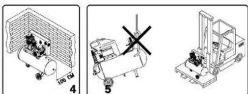
Always check whether the input voltage of the motor corresponds to the mains voltage indicated on the specification plate. The compressors are supplied with an electrical cable and a two-pole plug + earth. It is important to connect the compressor with an earthed plug socket. (fig. 9)

Never use the earth-wire instead of the neutral (0-wire). The earthing should take place in accordance with accident prevention regulations (EN 60204).
3. USE

For homehold use only
NB: The information you will find in this manual has been written to assist the operator in the use and maintenance of the compressor. Some illustrations in this manual show details which may differ from those of your compressor.
Installation
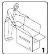
After having taken the compressor out of its packaging (fig. 1) and having checked that it is in perfect condition, and having noted that no damage occurred during transport, the following acts should be performed. If not yet fitted, fit the rubber feet on the tank according to the instructions represented in fig. 2. Place the compressor on a flat surface or at a maximum slope of 10^ (fig.3), in a well ventilated area, protected against atmospheric factors and not in explosive surroundings. If the surface area is sloping and smooth, make sure that the compressor will not move when in operation. If the surface area is a board or a shelf of a bookcase, just make sure that they cannot fall down by securing them properly. For proper ventilation and effective cooling, it is important that the compressor is positioned at least 100 cm from the wall (fig. 4).

Make sure that the compressor is transported in the right way, do not turn it upside down and don't lift it with hooks or ropes (fig. 5-6).
Important! Before commissioning
The carter of this compressor is filled with oil at the factory. To avoid leaking oil during transport, there is a liquid-proof sticker stuck on the oil cap.
Important! Remove the sticker before starting the compressor. The little gap in the oil cap is necessary for a correct ventilation of the carter. The gauge at the bottom of the sump indicates the oil level: this should now be level with the red dot (fig. 7 and 8).
Starting up
- Check whether the mains voltage corresponds to that indicated on the electrical specification plate (fig. 10), the permitted tolerance range should be within 5% .
- Press the switch situated on the upper part into the "0" position according to the pressure regulator type fitted on the device (fig. 11).
- Put the plug in the plug socket (fig. 9) and start the compressor up by putting the switch of the pressure regulator in the "I" position. The operation of the compressor is fully automatic. The pressure regulator will stop the compressor when the maximum value has been reached and start it up when the pressure drops below the minimum value. Normally the difference in pressure is approx. 2 Bar/29 psi between the maximum and the minimum value. For instance - The compressor will stop when it reaches 8 Bar (116 psi) (this is the maximum operating pressure) and will start up automatically when the pressure within the tank has dropped to 6 Bar (87 psi).

The headcylinder/transmission pipe assembly may reach high temperatures, so take care when working close to these parts and do not touch them to avoid burns (fig. 12 - 13).
Adjusting the operating pressure
Fig. 14
It is not necessary continuously to use the maximum operating pressure, the compressed-air tools often require less pressure. With regard to compressors supplied with a pressure reduction valve it is necessary to set the operating pressure properly. It is possible to set the operating pressure by using the turning knob on the reduction valve.
- By turning clockwise, the pressure will be increased.
- By turning anti-clockwise, the pressure will be reduced.
The compressor has two pressure gauges and two points to connect an air hose:
- Pressure gauge on the left: pressure on left outlet. The pressure of left this outlet can be regulated with help of the reduction valve.
- Pressure gauge on the right: tank pressure + pressure on right outlet
The set pressure can be locked by turning the ring under the turning knob in the opposite direction from the turning knob thereby fixing the turning knob. The set pressure is visible on the manometer of the reduction valve.
4.FAULTS
Air loss
- May be caused by a poor seal of a connection.
- Check all connections by wetting them with soap and water.
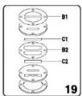
The compressor runs but does not compress Fig. 19
- May be caused by the valves (C-C2) or a gasket (B1-B2) being broken. - Replace the damaged part.
The compressor will not start
If the compressor is difficult to start, check:
- whether the voltage of the mains corresponds to that on the specification plate (fig. 10)
- whether electrical extension cables are being used with a faulty core or length.
- whether the operating environment is too cold (below 0^ ).
- whether there is oil in the sump to guarantee lubrication (fig. 8)
- whether there is electricity supply (plug properly connected, magneto-thermal fuses not broken).
The compressor does not shut off
If the compressor does not shut off when the maximum pressure has been reached, the safety valve of the tank will be activated. It is necessary to contact the nearest authorised Support Service for the repair.
5.MAINTENANCE
Maintenance

Make sure that the plug is removed from the mains when carrying out maintenance work on the motor.
The machines have been designed to operate over a long period of time with a minimum of maintenance. Continuous satisfactory operation depends upon proper machine care and regular cleaning. Before interfering in any way whatsoever with the compressor, please make sure that:
- The general line switch is in the "0" position.
- The pressure regulator and the switches on the switch board are switched off in the "0" position.
• The air tank is fully decompressed.
Cleaning
Regularly clean the machine housing with a soft cloth, preferably after each use. Keep the ventilation slots free from dust and dirt.
If the dirt does not come off use a soft cloth moistened with soapy water. Never use solvents such as petrol, alcohol, ammonia water, etc. These solvents may damage the plastic parts.
Lubrication
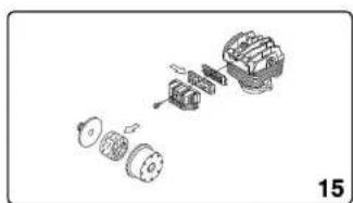
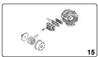
It is recommended to disassemble the suction filter every 50 operating hours and to clean the filter element by blowing it with compressed air (fig. 15). It is recommended that the filter element is replaced at least once a year if the compressor is working in a clean environment;
Start
more often if the environment in which the compressor is situated is dusty. The compressor makes condensed water which collects in the tank. It is necessary to remove the condensed water in the tank at least once a week by opening the drain cock (fig. 16) under the tank. Take care when compressed air is in the bottle because the water can come out with some force. Recommended pressure max. 1-2 Bar.

The condensed water of the oil lubricated compressor should not be disposed of in the sewers or be disposed of in the environment because it contains oil.
Replacing/topping up oil
The compressor has been supplied with synthetic oil "SAE 10W30". It is recommend to fully replace the oil of the pump system within the first 100 operating hours.
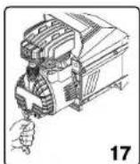
- Unscrew the drain plug (gauge) on the sump lid, let all the oil run out and screw back the plug (fig. 17).
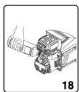
- Fill the oil via the upper hole of the sump lid (fig. 18) until the level indicated on the gauge (fig. 8) has been reached.
Check the oil level of the pump system every week and if necessary top up. The synthetic oil has the advantage that it does not lose its characteristics, either in summer or in winter periods.

You should not dispose of the used oil in the sewer or in the environment.
For replacement of oil the table below should be adhered to.
Oil type Operating hours
Multigrade oil SAE 10W30 100 or 6 months
Faults
Should a fault occur, e.g. after wear of a part, please contact the service address on the warranty card. In the back of this manual you find an exploded view showing the parts that can be ordered.
Environment
To prevent damage during transport, the appliance is delivered in a solid packaging which consists largely of reusable material. Therefore please make use of options for recycling the packaging.

Faulty and/or discarded electrical or electronic apparatus have to be collected at the appropriate recycling locations.
Warranty
The warranty conditions can be found on the separately enclosed warranty card.
CE DECLARATION OF CONFORMITY (GB)
We declare under our sole responsibility that this product conforms with the following standards or standardised documents:
EN1012-1, EN60204-1, EN55014-1, ISO5388, EN55014-2, EN61000-3-2, EN61000-3-3
in accordance with regulations:
98/37/IEC, 73/23/EEC, 89/336/IEEC, 87/404/IEEC, 2000/14/IEC, 2002/95/IEC, 2002/96/IEC
Measured sound power level; Lwa = 91.1 dB(A)
Guaranteed sound power level; Lwa = 91 dB(A)
2000/14/EC: The guaranteed sound power level Lwa is lower than 96 dB(A). Conformity assessment procedure according to Annex VI.
Notified body: TUV product service GmbH
Notified body identifications number: 70.403.06.078.13
from 01-08-2006
ZWOLLE NL

CEO Ferm BV Quality Manager Ferm Global
It is our policy to continuously improve our products and we therefore reserve the right to change the product specification without prior notice.
Ferm BV • Lingenstraat 6 • 8028 PM Zwolle • The Netherlands
CE ERKLÆRING AV ANSVARSFORHOLD (N)
Vi erklærer at det er under vårt ansvar at dette produkt er i overenstemmelse med fölgende standarder eller standard-dokumenter
EN1012-1, EN60204-1, EN55014-1, ISO5388, EN55014-2, EN61000-3-2, EN61000-3-3
i samsvar med direktivene:
98/37/EC, 73/23/EEC, 89/336/EEC, 87/404/EEC, 2000/14/EC, 2002/95/EC, 2002/96/EC
Mált lydstyrkenivá; Lwa = 91.1 dB(A)
CEO Ferm BV Quality Manager Ferm Global
CEO Ferm BV Quality Manager Ferm Global
CEO Ferm BV Quality Manager Ferm Global
Quality Manager Ferm Global
98/37/IEC, 73/23/EEC, 89/336/IEEC, 87/404/IEEC, 2000/14/IEC, 2002/95/IEC, 2002/96/IEC
Uppmätt ljudeffektnivå; Lwa = 91.1 dB(A)
Garanterad ljudeffektnivå; Lwa = 91 dB(A)
CEO Ferm BV Quality Manager Ferm Global
J. Lodewijk
CE DÉCLARATION DE CONFORMITÉ (F)
Quality Manager Ferm Global
Quality Manager Ferm Global
Quality Manager Ferm Global
natural_image
Technical line drawing of two mechanical components with wheels and a wheelbase (no text or symbols)
text_image
Technical diagrams showing three different mechanical or industrial setups with labeled components and dimensions
text_image
7 8 9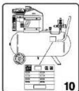

natural_image
Two technical diagrams showing mechanical components and warning symbols (no readable text or labels)
text_image
13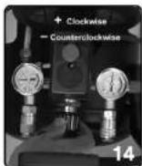
Ferm0358 Ferm
natural_image
Exploded view diagram of a mechanical assembly showing gears and housing (no text or labels)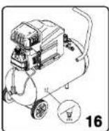


OLAJBÁZISÚ KOMPRESSZOR
CEO Ferm BV Quality Manager Ferm Global
CEO Ferm BV Quality Manager Ferm Global
98/37/IEC, 73/23/IEEC, 89/336/IEEC, 87/404/IEEC, 2000/14/IEC, 2002/95/IEC, 2002/96/IEC
CEO Ferm BV Quality Manager Ferm Global
CEO Ferm BV Quality Manager Ferm Global