
HWS-1402H-E - Heat pump TOSHIBA - Free user manual and instructions
Find the device manual for free HWS-1402H-E TOSHIBA in PDF.
User questions about HWS-1402H-E TOSHIBA
0 question about this device. Answer the ones you know or ask your own.
Ask a new question about this device
Download the instructions for your Heat pump in PDF format for free! Find your manual HWS-1402H-E - TOSHIBA and take your electronic device back in hand. On this page are published all the documents necessary for the use of your device. HWS-1402H-E by TOSHIBA.
USER MANUAL HWS-1402H-E TOSHIBA
natural_image
Technical line drawing of two TOSHIBA air conditioning units with fan blades (no text or symbols)| Installation manualAir to Water Heat Pump | 2 | English |
| Manuel d’installationPompe à chaleur air/eau | 24 | Français |
| Installations-handbuchLuft-/Wasserwärmepumpe | 46 | Deutsch |
| InstallationshandbokLuft-till-vatten-värmepump | 68 | Svenska |
Please read this Installation Manual carefully before installing the Air to Water Heat Pump.
- This Manual describes the installation method of the outdoor unit.
- For installation of the hydro unit, follow the Installation Manual attached to the hydro unit.
ADOPTION OF NEW REFRIGERANT
This Air to Water Heat Pump is a new type which adopts a new refrigerant HFC (R410A) instead of the conventional refrigerant R22 in order to prevent destruction of the ozone layer.
Contents
1 ACCESSORY PARTS AND REFRIGERANT .... 3
2 PRECAUTIONS FOR SAFETY 4
3 INSTALLATION OF NEW REFRIGERANT AIR TO WATER HEAT PUMP ..... 5
4 SELECTION OF INSTALLATION 7
5 REFRIGERANT PIPING 12
6 AIR PURGING 15
7 ELECTRICAL WORK 17
8 EARTHING 19
9 FINISHING 19
10 TEST RUN 19
11 ANNUAL MAINTENANCE 19
12 FUNCTIONS TO BE IMPLEMENTED LOCALLY 20
13 TROUBLESHOOTING 21
14 APPENDIX 22
1 ACCESSORY PARTS AND REFRIGERANT
■ Accessory parts
| Part name | Q'ty | Shape | Usage |
| Outdoor unit Installation manual | 1 | This manual | (Hand this directly to the customer.) |
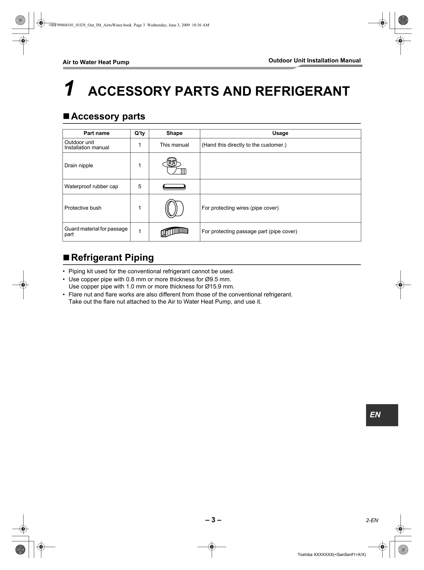
| Drain nipple | 1 | 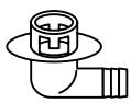 | |
| Waterproof rubber cap | 5 | 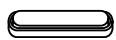 | |
| Protective bush | 1 |  | For protecting wires (pipe cover) |
| Guard material for passage part | 1 | 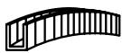 | For protecting passage part (pipe cover) |
■ Refrigerant Piping
- Piping kit used for the conventional refrigerant cannot be used.
- Use copper pipe with 0.8 mm or more thickness for ∅9.5 mm. Use copper pipe with 1.0 mm or more thickness for ∅15.9 mm.
- Flare nut and flare works are also different from those of the conventional refrigerant. Take out the flare nut attached to the Air to Water Heat Pump, and use it.
EN
2 PRECAUTIONS FOR SAFETY
- Ensure that all Local, National and International regulations are satisfied.
- Read this “PRECAUTIONS FOR SAFETY” carefully before Installation.
- The precautions described below include the important items regarding safety. Observe them without fail.
- After the installation work, perform a trial operation to check for any problem. Follow the Owner's Manual to explain how to use and maintain the unit to the customer.
- Turn off the main power supply switch (or breaker) before the unit maintenance.
- Ask the customer to keep the Installation Manual together with the Owner's Manual.
WARNING
- Ask an authorized dealer or qualified installation professional to install/maintain the Air to Water Heat Pump. Inappropriate installation may result in water leakage, electric shock or fire.
- Be sure to connect earth wire. (grounding work) Incomplete grounding cause an electric shock. Do not connect ground wires to gas pipes, water pipes, lightning rods or ground wires for telephone wires.
- Turn off the main power supply switch or breaker before attempting any electrical work. Make sure all power switches are off. Failure to do so may cause electric shock. Use an exclusive power circuit for the Air to Water Heat Pump. Use the rated voltage.
- Connect the connecting wire correctly. If the connecting wire is connected in a wrong way, electric parts may be damaged.
- When moving the Air to Water Heat Pump for the installation into another place, be very careful not to enter any gaseous matter other than the specified refrigerant into the refrigeration cycle. If air or any other gas is mixed in the refrigerant, the gas pressure in the refrigeration cycle becomes abnormally high and it may resultingly causes pipe burst and injuries on persons.
- Do not modify this unit by removing any of the safety guards or by by-passing any of the safety interlock switches.
• After unpacking the unit, examine it carefully if there are possible damage. - Do not install in a place that might increase the vibration of the unit.
- To avoid personal injury (with sharp edges), be careful when handling parts.
- Perform installation work properly according to the Installation Manual. Inappropriate installation may result in water leakage, electric shock or fire.
- When the Air to Water Heat Pump hydro unit is installed in a small room, provide appropriate measures to ensure that the concentration of refrigerant leakage occur in the room does not exceed the critical level.
- Tighten the flare nut with a torque wrench in the specified manner. Excessive tightening of the flare nut may cause a crack in the flare nut after a long period, which may result in refrigerant leakage.
- Wear heavy gloves during the installation work to avoid injury.
• Install the Air to Water Heat Pump securely in a location where the base can sustain the weight adequately. - Perform the specified installation work to guard against an earthquake. If the Air to Water Heat Pump is not installed appropriately, accidents may occur due to the falling unit.
- If refrigerant gas has leaked during the installation work, ventilate the room immediately. If the leaked refrigerant gas comes in contact with fire, noxious gas may generate.
- After the installation work, confirm that refrigerant gas does not leak. If refrigerant gas leaks into the room and flows near a fire source, such as a cooking range, noxious gas might generate.
- Electrical work must be performed by a qualified electrician in accordance with the Installation Manual. Make sure the Air to Water Heat Pump uses an exclusive power supply. An insufficient power supply capacity or inappropriate installation may cause fire.
- Use the specified wires for wiring connect the terminals securely fix. To prevent external forces applied to the terminals from affecting the terminals.
WARNING
- When the Air to Water Heat Pump cannot cool or heat water well, contact the dealer from whom you purchased the Air to Water Heat Pump as refrigerant leakage is considered as the cause. In the case of repair that requires refill of refrigerant, ask service personnel about details of the repair.
The refrigerant used in the Air to Water Heat Pump is harmless
Generally, the refrigerant does not leak. However, if the refrigerant leaks in a room and a heater or stove burner in the room catches fire, it may generate toxic gas.
When you ask service personnel for repairing refrigerant leakage, confirm that the leakage portion has been completely repaired.
- Conform to the regulations of the local electric company when wiring the power supply. Inappropriate grounding may cause electric shock.
- Do not install the Air to Water Heat Pump in a location subject to a risk of exposure to a combustible gas. If a combustible gas leaks, and stays around the unit, a fire may occur.
- Install the refrigerant pipe securely during the installation work before operating the Air to Water Heat Pump. If the compressor is operated with the valve open and without the refrigerant pipe, the compressor sucks air and the refrigeration cycle is overpressurized, which may cause a burst or injury.
- For the refrigerant recovery work (collection of refrigerant from the pipe to the compressor), stop the compressor before disconnecting the refrigerant pipe.
If the refrigerant pipe is disconnected while the compressor is working with the valve open, the compressor sucks air and the refrigeration cycle is overpressurized, which may cause a burst or injury.
CAUTION
New Refrigerant Air to Water Heat Pump Installation
- THIS AIR TO WATER HEAT PUMP ADOPTS THE NEW HFC REFRIGERANT (R410A) WHICH DOES NOT DESTROY OZONE LAYER.
- The characteristics of R410A refrigerant are ; easy to absorb water, oxidizing membrane or oil, and its pressure is approx. 1.6 times higher than that of refrigerant R22. Accompanied with the new refrigerant, refrigerating oil has also been changed. Therefore, during installation work, be sure that water, dust, former refrigerant, or refrigerating oil does not enter the refrigerating cycle.
- To prevent charging an incorrect refrigerant and refrigerating oil, the sizes of connecting sections of charging port of the main unit and installation tools are changed from those for the conventional refrigerant.
- Accordingly the exclusive tools are required for the new refrigerant (R410A).
- For connecting pipes, use new and clean piping designed for R410A, and please care so that water or dust does not enter.
To Disconnect the Appliance from Main Power Supply
- This appliance must be connected to the main power supply by means of a switch with a contact separation of at least 3 mm.
- The installation fuse 25 A (All type fuse can be used) must be used for the power supply line of this unit.
3 INSTALLATION OF NEW REFRIGERANT AIR TO WATER HEAT PUMP
- The R410A refrigerant is more susceptible to impurities such as water, oxide membrane, oils, and fats. With the adoption of the new refrigerant, refrigerating oil has also been changed.
Be careful so that water, dust, conventional refrigerant, and/or conventional refrigerating oil do not enter the refrigerating cycle of the new refrigerant Air to Water Heat Pump.
- To prevent different refrigerant or refrigerating oil being mixed, the sizes of the charging port of the unit and the installation tool connecting sections are different from the conventional refrigerant. Accordingly the following exclusive tools are required for the new refrigerant R410A.
■ Required Tools/Equipment and Precautions for Use
Prepare the tools and equipment listed in the following table before starting installation work.
Newly prepared tools and equipment must be used exclusively.
Legend
△: Prepared newly (Use for R410A only. Do not use for refrigerant R22 or R407C etc..)
◎ : Conventional tools/equipment are available
| Tools/equipment | Use | How to use tools/equipment |
| Gauge manifold | Vacuuming/charging refrigerant and operation check | Prepared newly for R410A only |
| Charging hose | Prepared newly for R410A only | |
| Charging cylinder | Can not be used | Unusable (Use the refrigerant charging measure instead.) |
| Gas leak detector | Gas leak check | Prepared newly |
| Vacuum pump with backflow prevention function | Vacuum drying | Unusable |
| Vacuum pump with backflow prevention function | Vacuum drying | R22 (Conventional tools) |
| Flare tool | Flare machining of pipes | Usable if dimensions are adjusted. |
| Bender | Bending pipes | R22 (Conventional tools) |
| Refrigerant recovery equipment | Refrigerant recovery | For R410A only |
| Torque wrench | Tightening flare nuts | Exclusive for 12.7 mm and 15.9 mm |
| Pipe cutter | Cutting pipes | R22 (Conventional tools) |
| Refrigerant cylinder | Charging refrigerant | For R410A onlyDiscriminated by the refrigerant name on the cylinder. |
| Welding machine and nitrogen cylinder | Welding pipes | R22 (Conventional tools) |
| Refrigerant charging measure | Charging refrigerant | R22 (Conventional tools) |
■ Refrigerant Piping
New refrigerant (R410A)
When using the conventional piping kit
- When using the conventional piping kit that has no indication of applicable refrigerant types, be sure to use it with a wall thickness of 0.8 mm for ∅6.4 mm, ∅9.5 mm, and ∅12.7 mm, and with a wall thickness of 1.0 mm for ∅15.9 mm. Never use the conventional piping kit with a wall thickness less than these thicknesses due to insufficient pressure capacity.
When using general copper pipes
- Use general copper pipes with a wall thickness of 0.8 mm for ∅6.4 mm, ∅9.5 mm, and ∅12.7 mm, and with a wall thickness of 1.0 mm for ∅15.9 mm.
Never use any copper pipes with a wall thickness less than these thicknesses.
Flare nuts and flare machining
- The flare nuts and flare machining are different from those for the conventional refrigerant.
Use the flare nuts supplied with the Air to Water Heat Pump or those for R410A.
- Before performing flare machining, carefully read “REFRIGERANT PIPING”
4 SELECTION OF INSTALLATION
■ Before installation
Be careful to the following items before installation.
Length of refrigerant pipe
| Length of refrigerant pipe connected to hydro/outdoor unit | Item |
| 3 m to 30 m | Addition of refrigerant is unnecessary at the local site. |
* Do not connect a refrigerant pipe shorter than 3 m. This may cause a malfunction of the compressor or other devices.
■ Airtight test
- Before starting an airtight test, further tighten the spindle valves on the gas side and liquid side.
- Pressurize the pipe with nitrogen gas charged from the service port to the design pressure (4.15 Mpa) to conduct the airtight test.
- After the airtight test is completed, evacuate the nitrogen gas.
Air purge
- For air purge, use a vacuum pump.
- Do not use refrigerant charged in the outdoor unit for air purge. (The refrigerant for air purge is not contained in the outdoor unit.)
Electrical wiring
Be sure to fix the power wires and hydro/outdoor connecting wires with clamps so that they do not contact with the cabinet, etc.
Earthing
WARNING
Make sure that proper earthing is provided.
Improper earthing may cause electric shock. For how to check earthing, contact the dealer who installed the Air to Water Heat Pump or a professional installation company.
- Proper earthing can prevent charging of electricity on the outdoor unit surface due to high frequency of the frequency converter (inverter) in the outdoor unit, as well as prevent electric shock. If the outdoor unit is not properly earthed, you may feel electric shock.
- Be sure to connect earth wire. (grounding work) Incomplete grounding cause an electric shock. Do not connect ground wires to gas pipes, water pipes, lightning rods or ground wires for telephone wires.
Test Run
- Start test run when the water piping work is completed and the system is filled with the proper amount of water.
- Turn on the leakage breaker at least 12 hours before starting a test run to protect the compressor during startup.
CAUTION
Incorrect work may result in a malfunction or complaints of customers.
■ Installation Place

WARNING
Install the outdoor unit properly at a place that is durable enough to the weight of the outdoor unit.
Insufficient durability may cause the outdoor unit to fall, which may result in injury.

CAUTION
Do not install the outdoor unit at a place subject to combustible gas leak.
Accumulation of combustible gas around the outdoor unit may cause a fire.
Install the outdoor unit at a place that meets the following conditions after customer's consent is obtained.
- A well-ventilated place free from obstacles near the air inlets and air outlet
- A place that is not exposed to rain or direct sunlight
- A place that does not increase the operating noise or vibration of the outdoor unit
- A place that does not cause any drainage problem with discharged water
Do not install the outdoor unit at the following places.
- A place full of saline atmosphere (coastal area) or sulfide gas (hot-spring area)
(Special maintenance is required.) - A place subject to oil, vapor, oily smoke, or corrosive gas
• A place where organic solvent is used - A place where high-frequency equipment (including inverter equipment, private power generator, medical equipment, and communication equipment) is used (Installation in this place may cause malfunction of the Air to Water Heat Pump, abnormal control or problems due to noise to such equipment.)
- A place where the discharged air of the outdoor unit blows against the window of the neighboring house
- A place where the operating noise of the outdoor unit is transmitted
- When the outdoor unit is installed in an elevated position, be sure to secure its feet.
- A place where the drain water does not make any problem.

CAUTION
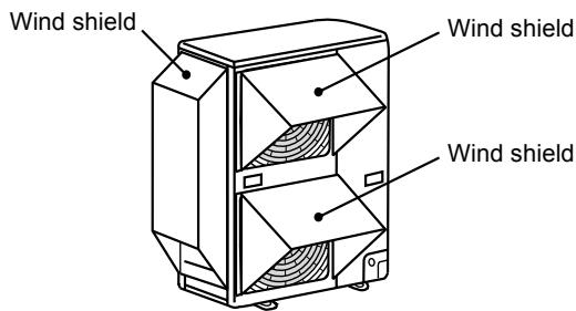
- Install the outdoor unit at a place where discharge air is not blocked.
- When an outdoor unit is installed in a place that is always exposed to a strong wind like a coast or on a high storey of a building, secure a normal fan operation by using a duct or a wind shield.
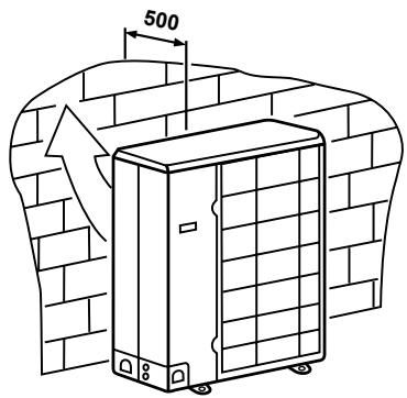
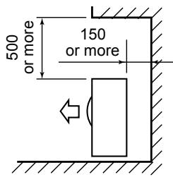
- When installing the outdoor unit in a place that is constantly exposed to a strong wind such as the upper stairs or rooftop of a building, apply the windproof measures referring to the following examples.
1) Install the unit so that its discharge port faces to the wall of the building. Keep a distance 500 mm or more between the unit and the wall surface.
natural_image
Line drawing of a refrigerated industrial cabinet with a 500 mm height dimension, set against a brick wall background (no text or symbols)2) Supposing the wind direction during the operation season of the Air to Water Heat Pump, install the unit so that the discharge port is set at right angle to the wind direction.

- When using an Air to Water Heat Pump under low outside temperature condition (Outside temp.:-5 °C or lower) with COOL mode, prepare a duct or wind shield so that it is not affected by the wind.
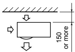
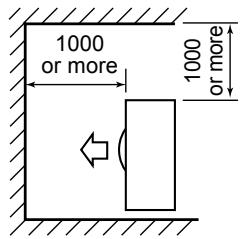
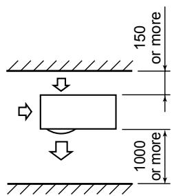
■ Necessary Space for Installation
(Unit:mm)
Obstacle at rear side
▼ Upper side is free
- Single unit installation
- Obstacles at both right and left sides
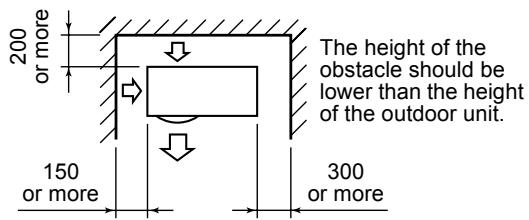
- Serial installation of two or more units
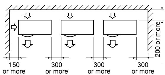
The height of the obstacle should be lower than the height of the outdoor unit.
▼ Obstacle also at the upper side
Obstacle at front side
▼ Upper side is free
- Single unit installation
- Serial installation of two or more units
▼ Obstacle also at the upper side
Obstacles at both front and rear sides
Open the upper side and both right and left sides. The height of obstacle at both front and rear side, should be lower than the height of the outdoor unit.
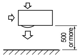
▼ Standard installation
- Single unit installation
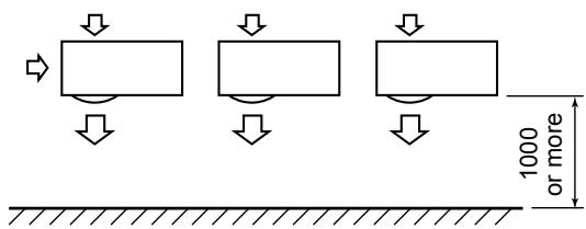
2. Serial installation of two or more units
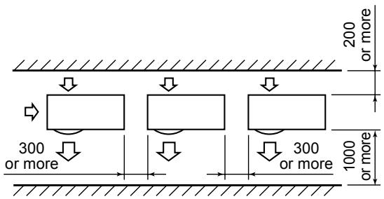
Serial installation at front and rear sides
Open the upper side and both right and left sides. The height of obstacle at both front and rear sides should be lower than the height of the outdoor unit.
▼ Standard installation

■ Installation of Outdoor Unit
- Before installation, check strength and horizontality of the base so that abnormal sound does not generate.
- According to the following base diagram, fix the base firmly with the anchor bolts.
(Anchor bolt, nut: M10 x 4 pairs)
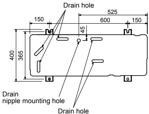
- As shown in the figure below, install the foundation and vibration-proof rubbers to directly support the bottom surface of the fixing leg that is in contact with the bottom plate of the outdoor unit.
* When installing the foundation for an outdoor unit with downward piping, consider the piping work.
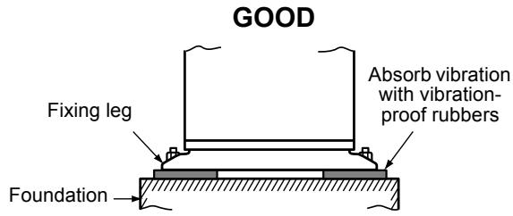
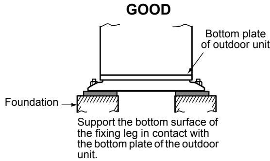
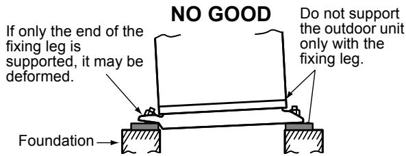
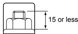
Set the out margin of the anchor bolt to 15 mm or less.
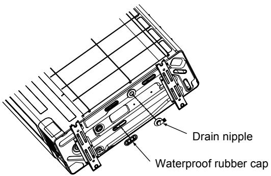
- In case of draining through the drain hose, attach the following drain nipple and the waterproof rubber cap, and use the drain hose (Inner diam.: 16 mm) sold on the market. And also seal the screws securely with silicone material, etc. so that water does not drop down. Some conditions may cause dewing or dripping of water.
- When collectively draining discharged water completely, a drain pan must be made locally.
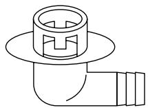
Drain nipple
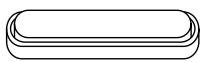
Waterproof rubber cap (5pcs.)
■ For Reference
If a heating operation would be continuously performed for a long time under the condition that the outdoor temperature is 0 °C or lower, draining of defrosted water may be difficult due to freezing of the bottom plate, resulting in a trouble of the cabinet or fan. It is recommended to procure an anti-freeze heater locally for a safety installation of the Air to Water Heat Pump.
For details, contact the dealer.
5 REFRIGERANT PIPING
■ Knockout of Pipe Cover
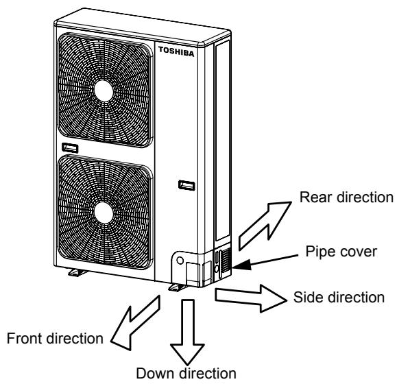
Knockout procedure
- The hydro/outdoor connecting pipes can be connected to 4 directions.
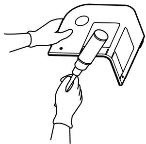
Take off the knockout part of the pipe cover in which pipes or wires pass through the base plate. - Detach the piping cover and give an impact on the knockout section a few times with the shank of a screwdriver. A knockout hole can easily be punched.
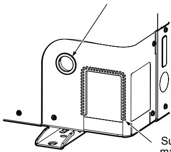
- After punching the knockout hole, remove burrs of the hole and then install the supplied protective bush and guard material for passage part to protect wires and pipes.
Be sure to attach the pipe covers after pipes have been connected. Cut the slits under the pipe covers to facilitate the installation.
After connecting the pipes, be sure to mount the pipe cover. The pipe cover is easily mounted by cutting off the slit at the lower part of the pipe cover.
natural_image
Line drawing of hands using a tool to adjust or install a device (no text or symbols visible)* Be sure to wear heavy work gloves while working.
Supplied protective bush
natural_image
Technical line drawing of a mechanical housing or enclosure component with mounting flanges and a central square opening (no text or symbols)Supplied passage hole guard material
* Attach the guard material securely so that it does not come loose.
■ Optional Installation Parts (Local Procure)
| Parts name | Q'ty | |
| A | Refrigerant pipingLiquid side : ∅9.5 mmGas side : ∅15.9 mm | Each one |
| B | Pipe insulating material(polyethylene foam, 10 mm thick) | 1 |
| C | Putty, PVC tapes | Each one |
■ Refrigerant Piping Connection

CAUTION
TAKE NOTICE THESE IMPORTANT 4 POINTS BELOW FOR PIPING WORK
- Keep dust and moisture away from inside the connecting pipes.
- Tightly connect the connection between pipes and the unit.
- Evacuate the air in the connecting pipes using VACUUM PUMP.
- Check gas leak at connected points.
▼ Piping connection
| Liquid side | Gas side | ||
| Outer diameter | Thickness | Outer diameter | Thickness |
| 9.5 mm | 0.8 mm | 15.9 mm | 1.0 mm |
Flaring
- Cut the pipe with a pipe cutter. Be sure to remove burrs that may cause gas leak.
- Insert a flare nut into the pipe, and then flare the pipe.
Use the flare nuts supplied with the Air to Water Heat Pump or those for R410A.
Insert a flare nut into the pipe, and flare the pipe. As the flaring sizes of R410A differ from those of refrigerant R22, the flare tools newly manufactured for R410A are recommended.
However, the conventional tools can be used by adjusting projection margin of the copper pipe.
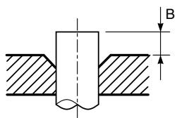
▼ Projection margin in flaring : B (Unit : mm) Rigid (Clutch type)
| Outer diam. of copper pipe | R410A tool used | Conventional tool used |
| R410A | 1.0 to 1.5 | |
| 9.5 | 0 to 0.5 | |
| 15.9 |
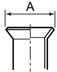
▼ Flare nut width: H and flare matching size: A.
Flare nut width: H
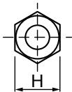
(mm)
| Copper pipe outer diam. | ∅6.4 | ∅9.5 | ∅12.7 | ∅15.9 | ∅19.0 |
| For R410A | 17 | 22 | 26 | 29 | 36 |
Flare machining size: A
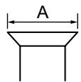
A +0, -0.4
| Copper pipe outer diam. | ∅6.4 | ∅9.5 | ∅12.7 | ∅15.9 | ∅19.0 |
| For R410A | 9.1 | 13.2 | 16.6 | 19.7 | 24.0 |
Do not apply the refrigerator oil to the flare surface.
* In case of flaring for R410A with the conventional flare tool, pull it out approx. 0.5 mm more than that for R22 to adjust to the specified flare size.
The copper pipe gauge is useful for adjusting projection margin size.
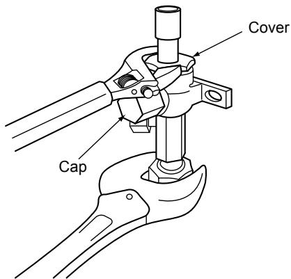
■ Tightening of Connecting Part
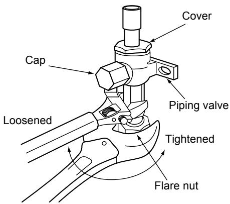
- Align the centers of the connecting pipes and fully tighten the flare nut with fingers. Then fix the nut with a spanner as shown in the figure and tighten it with a torque wrench.
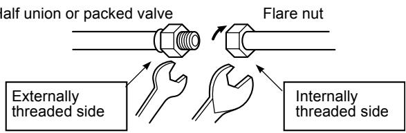
- As shown in the figure, be sure to use two spanners to loosen or tighten the flare nut of the valve on the gas side. If you use a single spanner, the flare nut cannot be tightened to the required tightening torque.
On the other hand, use a single spanner to loosen or tighten the flare nut of the valve on the liquid side.
(Unit: N•m)
| Outer diam. of copper pipe | Tightening torque |
| 9.5 mm (diam.) | 33 to 42 (3.3 to 4.2 kgf•m) |
| 15.9 mm (diam.) | 68 to 82 (6.8 to 8.2 kgf•m) |
Fix with spanner.
Tighten with torque wrench.
Valve at gas side

CAUTION
- Do not put the spanner on the cap or cover. The valve may be broken.
- If applying excessive torque, the nut may be broken according to some installation conditions.
- After the installation work, be sure to check gas leak of connecting part of the pipes with nitrogen.
NO GOOD
- Pressure of R410A is higher than that of R22 (Approx. 1.6 times).
Therefore, using a torque wrench, tighten the flare pipe connecting sections which connect the hydro/outdoor units at the specified tightening torque. Incomplete connections may cause not only a gas leak, but also a trouble of the refrigeration cycle.
Do not apply refrigerating machine oil to the flared surface.
■ Refrigerant Pipe Length
Refrigeration pipe
H: max. ±30 m (above/below)
L: max. 30 m, min. 3 m
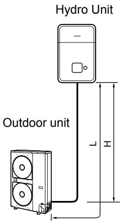
30 m chargeless
6 AIR PURGING
■ Airtight test
Before starting an airtight test, further tighten the spindle valves on the gas side and liquid side.
Pressurize the pipe with nitrogen gas charged from the service port to the design pressure (4.15 Mpa) to conduct the airtight test.
After the airtight test is completed, evacuate the nitrogen gas.
Air Purge
With respect to the preservation of terrestrial environment, adopt “Vacuum pump” for air purge (Evacuate air in the connecting pipes) when installing the unit.
- Do not discharge the refrigerant gas to the atmosphere to preserve the terrestrial environment.
- Use a vacuum pump to discharge the air (nitrogen, etc.) remained in the set. If the air remains, the capacity may decrease.
For the vacuum pump, be sure to use one with backflow preventer so that the oil in the pump does not backflow into the pipe of the Air to Water Heat Pump when the pump stops.
(If oil in the vacuum pump is put in an Air to Water Heat Pump including R410A, it may cause trouble on the refrigeration cycle.)
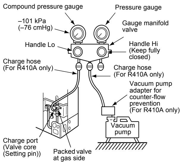
Vacuum pump
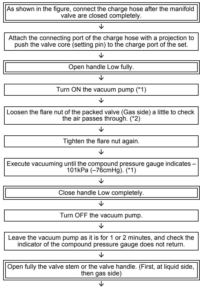
flowchart
graph TD
    A["As shown in the figure, connect the charge hose after the manifold valve are closed completely."] --> B["Attach the connecting port of the charge hose with a projection to push the valve core (setting pin) to the charge port of the set."]
    B --> C["Open handle Low fully."]
    C --> D["Turn ON the vacuum pump (*1)"]
    D --> E["Loosen the flare nut of the packed valve (Gas side) a little to check the air passes through. (*2)"]
    E --> F["Tighten the flare nut again."]
    F --> G["Execute vacuuming until the compound pressure gauge indicates – 101kPa (–76cmHg). (*1)"]
    G --> H["Close handle Low completely."]
    H --> I["Turn OFF the vacuum pump."]
    I --> J["Leave the vacuum pump as it is for 1 or 2 minutes, and check the indicator of the compound pressure gauge does not return."]
    J --> K["Open fully the valve stem or the valve handle. (First, at liquid side, then gas side)."]
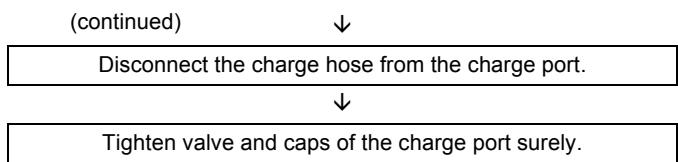
flowchart
graph TD
    A["Disconnect the charge hose from the charge port."] --> B["Tighten valve and caps of the charge port surely."]
    A --> C["(continued)"]
*1 Use the vacuum pump, vacuum pump adapter, and gauge manifold correctly referring to the manuals supplied with each tool before using them.
Check that the vacuum pump oil is filled up to the specified line of the oil gauge.
*2 When air is not charged, check again whether the connecting port of the discharge hose, which has a projection to push the valve core, is firmly connected to the charge port.
How to open the valve
Confirm the structure surely and then open or close the valve.
▼ Liquid side
Open the valve with a 4-mm hexagon wrench.
▼ Gas side
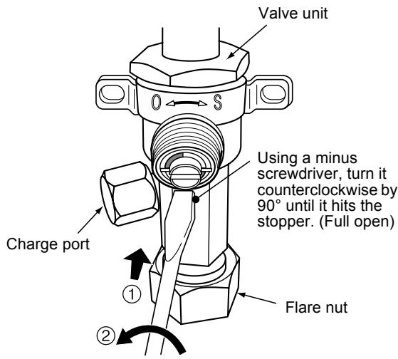
Handle position
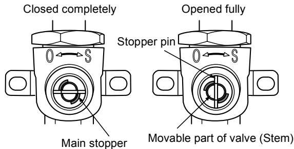
- While the valve is fully opened, after the screwdriver has reached the stopper, do not apply torque exceeding 5N•m. Applying excessive torque may damage the valve.
Valve handling precautions
- Open the valve stem until it strikes the stopper. It is unnecessary to apply further force.
- Securely tighten the cap with a torque wrench.
- Cap tightening torque
| Valve size | ∅9.5 mm | 33 to 42 N•m (3.3 to 4.2 kgf•m) |
| ∅15.9 mm | 20 to 25 N•m (2.0 to 2.5 kgf•m) | |
| Charge port | 14 to 18 N•m (1.4 to 1.8 kgf•m) | |
■ Replenishing refrigerant
This model is a 30 m chargeless type that does not need to replenish refrigerant for refrigerant pipes up to 30 m.
Refrigerant replenishing procedure
- After the vacuuming of the refrigerant pipe is completed, close the valves and then charge refrigerant while the Air to Water Heat Pump is not working.
- When the refrigerant cannot be charged to the specified amount, charge the required amount of refrigerant from the charge port of the valve on the gas side during cooling.
Requirement for replenishing refrigerant
Replenish liquid refrigerant.
When gaseous refrigerant is replenished, the refrigerant composition varies, which disables normal operation.
Additional amount of refrigerant
The refrigerant need not be reduced for a 30 meter (or less) refrigerant pipe.
7 ELECTRICAL WORK

WARNING
- Using the specified wires, ensure to connect the wires, and fix wires securely so that the external tension to the wires do not affect the connecting part of the terminals.
Incomplete connection or fixation may cause a fire, etc. - Be sure to connect earth wire. (grounding work) Incomplete grounding cause an electric shock.
Do not connect ground wires to gas pipes, water pipes, lightning rods or ground wires for telephone wires. - Appliance shall be installed in accordance with national wiring regulations.
Capacity shortage of power circuit or incomplete installation may cause an electric shock or a fire.

CAUTION
- Wrong wiring may cause a burn-out to some electrical parts.
- Be sure to use the cord clamps attached to the product.
- Do not damage or scratch the conductive core and inner insulator of power and inter-connecting wires when peeling them.
-
Use the power and Inter-connecting wires with specified thickness, specified type and protective devices required.
-
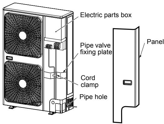
Remove the panel, and you can see electric parts on the front side.
- A metal pipe can be installed through the hole for wiring. If the hole size does not fit the wiring pipe to be used, drill the hole again to an appropriate size.
- Be sure to clamp the power wires and hydro/outdoor connecting wires with banding band along the connecting pipe so that the wires do not touch the compressor or discharge pipe. (The compressor and the discharge pipe become hot.)
Furthermore, be sure to secure these wires with the pipe valve fixing plate and cord clamps stored in the electric parts box.
■ Wiring between Hydro Unit and Outdoor Unit
The dashed lines show on-site wiring.
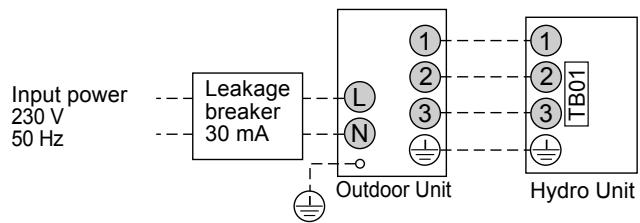
flowchart
graph LR
    A["Input power 230 V\n50 Hz"] --> B["Leakage breaker 30 mA"]
    B --> C["Outdoor Unit"]
    C --> D["Hydro Unit"]
    style A fill:#f9f,stroke:#333
    style D fill:#bbf,stroke:#333
- Connect the hydro/outdoor connecting wires to the identical terminal numbers on the terminal block of each unit.
Incorrect connection may cause a failure.
For the Air to Water Heat Pump, connect a power wire as mentioned below.
| Model HWS- | 802H-E | 1102H-E | 1402H-E |
| Power supply | 230 V~, 50 Hz | ||
| Maximum running current | 20.8 A | 22.8 A | |
| Installation fuse rating | 25 A(all types can be used) | ||
| Power wire | H07 RN-F or 60245 IEC 66(2.5 mm2 or more) | ||
| Hydro/outdoor connecting wires | H07 RN-F or 60245 IEC 66(1.5 mm2 or more) | ||
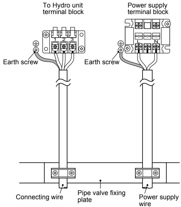
How to wire
- Connect the connecting wire to the terminal as identified with their respective numbers on the terminal block of hydro and outdoor unit.
H07 RN-F or 60245 IEC 66 (1.5 mm ^4 or more) - When connecting the connecting wire to the outdoor unit terminal, prevent water coming in the outdoor unit.
- Insulate the unsheathed cords (conductors) with electrical insulation tape. Process them so that they do not touch any electrical or metal parts.
- For inter connecting wire, do not use a wire jointed to another on the way.
Use wires long enough to cover the entire length.
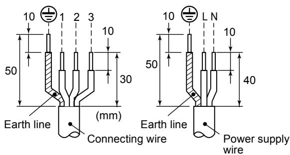
Stripping length power cord and connecting wire
CAUTION
- The installation fuse must be used for the power supply line of this outdoor unit.
- Incorrect/incomplete wiring might cause an electrical fire or smoke.
- Prepare the exclusive power supply for the Air to Water Heat Pump.
- This product can be connected to the mains. Connection to the fixed wiring: A switch which disconnects all poles and has a contact separation of at least 3 mm must be incorporated in the fixed wiring.
8 EARTHING

WARNING
- Be sure to connect earth wire. (grounding work)
Incomplete grounding cause an electric shock.
Connect the earth line properly following applicable technical standards.
Connecting an earth line is essential to prevent electric shock and to reduce noise and electricity charge on the outdoor unit surface due to high frequency generated by the frequency converter (inverter) in the outdoor unit.
If you touch the charged outdoor unit without earth line, you may feel electric shock.
9 FINISHING
After the refrigerant pipe and the inter-unit wires have been connected, cover them with finishing tape and clamp them to the wall with off-the-shelf support brackets or equivalent.
Keep the power wires and hydro/outdoor connecting wires off the valve on the gas side or pipes that have no heat insulator.
10TEST RUN
- The test run, on the outdoor unit, can only be completed when the complete Air to Water Heat Pump system has been installed. (Hydro unit, heating system or/and the others)
- Please refer to the hydro unit installation manual for the details of the test run procedure.
- For Air to Water system which is operated regularly, cleaning and maintenance of the hydro/outdoor units are strongly recommended.
As a general rule, if an hydro unit is operated for about 8 hours daily, the hydro/outdoor units will need to be cleaned at least once every 3-month. This cleaning and maintenance shall be carried out by a qualified person. Failure to clean the hydro/outdoor units regularly will result in poor performance, icing, water leaking and even compressor failure.
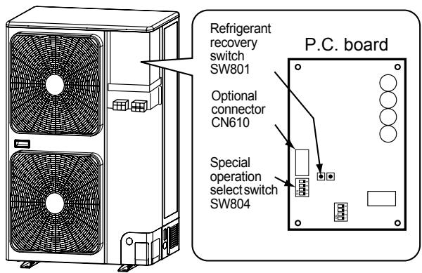
12 FUNCTIONS TO BE IMPLEMENTED LOCALLY
■ Recovering Refrigerant
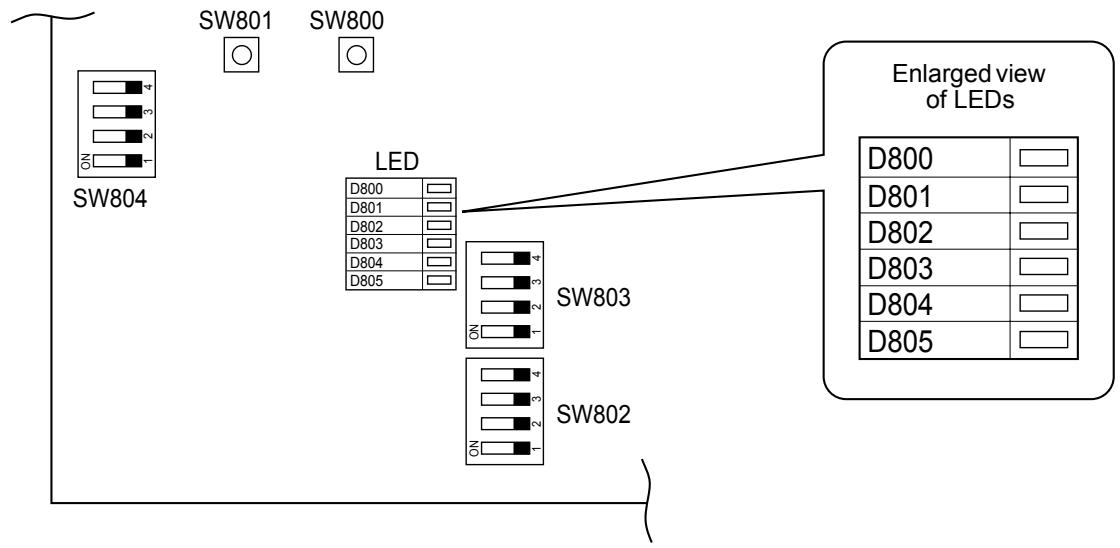
- Use the refrigerant recovery switch SW801 on the P.C. board of the outdoor unit to recover refrigerant when the hydro unit or outdoor unit is moved.
Procedure
- Drain off the water in the hydro unit.
- Turn on the power of the Air to Water Heat Pump.
- Set SW804 on the P.C. board of the outdoor unit to all OFF, and then press SW801 for one second or more. The Air to Water Heat Pump enters the forced cooling mode for up to 10 minutes. Operation or handling the valve to recover refrigerant during this time period.
- Upon completion of refrigerant recovery, close the valve and press SW801 for at least one second to stop operation.
- Turn off the power.

DANGER
Take care for an electric shock because the P.C.board is electrified.
13 TROUBLESHOOTING
You can perform fault diagnosis of the outdoor unit with the LEDs on the P.C. board of the outdoor unit in addition to check codes displayed on the wired remote controller of the hydro unit.
Use the LEDs and check codes for various checks. Details of check codes displayed on the wired remote controller of the hydro unit are described in the Installation Manual of the hydro unit.
Check of the current abnormal status
- Check that DIP switch SW803 is set to all OFF.
- Jot down the states of LED800 to LED804. (Display mode 1)
- Press SW800 for at least one second. The LED status changes to display mode 2.
- Check the code whose display mode 1 equals the jotted LED status and display mode 2 equals the current flashing status of LED800 to LED804 from the following table to identify the cause.
Check of the abnormal status in the past although the abnormal status is not occurred now.
- Set bit 1 of DIP switch SW803 to ON.
- Jot down the states of LED800 to LED804. (Display mode 1)
- Press SW800 for at least one second. The LED status changes to display mode 2.
- Find an error whose display mode 1 equals the jotted LED status and display mode 2 equals the current flashing status of LED800 to LED804 from the following table to identify the error.
- An outside air temperature (TO) sensor error can be checked only while an error occurs.
| No. | Cause | Display mode 1 | Display mode 2 | ||||||||
| D800 | D801 | D802 | D803 | D804 | D800 | D801 | D802 | D803 | D804 | ||
| 1 | Normal | ● | ● | ● | ● | ● | ● | ● | ● | ● | ● |
| 2 | Discharge (TD) sensor error | ○ | ○ | ● | ● | ○ | ● | ● | ◎ | ● | ● |
| 3 | Heat exchanger (TE) sensor error | ○ | ○ | ● | ● | ○ | ● | ◎ | ◎ | ● | ● |
| 4 | Heat exchanger (TL) sensor error | ○ | ○ | ● | ● | ○ | ◎ | ◎ | ◎ | ● | ● |
| 5 | Outside air temperature (TO) sensor error | ○ | ○ | ● | ● | ○ | ● | ● | ● | ◎ | ● |
| 6 | Suction (TS) sensor error | ○ | ○ | ● | ● | ○ | ● | ● | ◎ | ◎ | ● |
| 7 | Heat sink (TH) sensor error | ○ | ○ | ● | ● | ○ | ◎ | ● | ◎ | ◎ | ● |
| 8 | Outdoor temperature sensor (TE/TS) connection error | ○ | ○ | ● | ● | ○ | ◎ | ◎ | ◎ | ◎ | ● |
| 9 | Outdoor EEPROM error | ○ | ○ | ● | ● | ○ | ◎ | ◎ | ◎ | ◎ | ◎ |
| 10 | Compressor lock | ● | ● | ○ | ● | ○ | ◎ | ● | ● | ● | ● |
| 11 | Compressor lock | ● | ● | ○ | ● | ○ | ● | ◎ | ● | ● | ● |
| 12 | Current detect circuit error | ● | ● | ○ | ● | ○ | ◎ | ◎ | ● | ● | ● |
| 13 | Thermostat for compressor activated | ● | ● | ○ | ● | ○ | ● | ● | ◎ | ● | ● |
| 14 | Model data not set(on the service P.C. board) | ● | ○ | ○ | ● | ○ | ● | ◎ | ● | ◎ | ● |
| 15 | MCU-MCU communication error | ● | ○ | ○ | ● | ○ | ◎ | ● | ◎ | ◎ | ◎ |
| 16 | Discharge temperature error | ○ | ○ | ○ | ● | ○ | ◎ | ◎ | ● | ● | ● |
| 17 | Abnormal power(open phase detected or abnormal voltage) | ○ | ○ | ○ | ● | ○ | ◎ | ● | ◎ | ● | ● |
| 18 | Heat sink overheat | ○ | ○ | ○ | ● | ○ | ◎ | ◎ | ◎ | ● | ● |
| 19 | Gas leak detected | ○ | ○ | ○ | ● | ○ | ◎ | ◎ | ◎ | ◎ | ● |
| 20 | 4-way valve reverse error | ○ | ○ | ○ | ● | ○ | ◎ | ◎ | ● | ● | ◎ |
| 21 | High pressure release operation | ○ | ○ | ○ | ● | ○ | ● | ● | ◎ | ● | ◎ |
| 22 | Outdoor fan motor error | ○ | ○ | ○ | ● | ○ | ● | ◎ | ◎ | ● | ◎ |
| 23 | Compressor driver short-circuit protection | ○ | ○ | ○ | ● | ○ | ● | ◎ | ● | ◎ | ◎ |
| 24 | Position detect circuit error in one-line display | ○ | ○ | ○ | ● | ○ | ◎ | ● | ◎ | ◎ | ◎ |
(●:OFF ○:ON ◎:Flashing)
* The LEDs and DIP switches are located at the lower left of the P.C. board of the outdoor unit.
flowchart
graph TD
    A["SW804"] --> B["LED"]
    B --> C["SW803"]
    B --> D["SW802"]
    E["SW801"] --> F["ENLARGED VIEW OF LEDs"]
    G["SW800"] --> H["ENLARGED VIEW OF LEDs"]
    I["ON"] --> J["ON"]
    K["ON"] --> L["ON"]
    M["ON"] --> N["ON"]
    O["ON"] --> P["ON"]
    Q["D800"] --> R[" "] --> S["D801"] --> T[" "] --> U["D802"] --> V[" "] --> W["D803"] --> X[" "] --> Y["D804"] --> Z[" "] --> AA["D805"]
14 APPENDIX
Curing of pipes
When removing and opening the hydro unit or outdoor unit for a long time, cure the pipes as follows:
- Otherwise rust may generate when moisture or foreign matter due to dewing enters in the pipes.
- The rust cannot be removed by cleaning, and a new piping work is necessary.
| Place position | Term | Curing manner |
| Outdoors | 1 month or more | Pinching |
| Less than 1 month | Pinching or taping | |
| Hydro units | Every time |

natural_image
Symbol of a trash bin crossed with no text or labels, representing no waste or elimination (no text present)
IMPORTANT INFORMATION AND WARNING:
READ BEFORE INSTALLING THE UNIT. KEEP IN A SAFE PLACE THE INFORMATION IN THIS BOOKLET IS NEEDED FOR END OF LIFE, DISPOSAL OR REUSE OF THE UNIT
• We are very sensitive to environment and welcomes the 2002/96/EC Directive WEEE (Waste Electrical and Electronic Equipment).
- This product is compliant with EU directive 2002/96/EC. It must be collected separately after its use is completed, and cannot be disposed as unsorted municipal waste.
- The objective of EU directive 2002/96/EC are to tackle the fast increasing waste stream of electrical and electronic equipment, increase recycling of electric & electronic equipment ("EEE"), and to limit the total quantity of waste EEE ("WEEE") going to final disposal.
- The crossed out wheeled bin symbol 📋 that is affixed to the product means that this product falls under the Directive.
- The user is responsible for returning the product to the appropriate collection facility, as specified by your municipality or the distributor. In case of installation of a new product, it may be possible to have the distributor pick up old WEEE directly.
- The producer, importer and distributor of are responsible for collection and treatment of waste, either directly or through a collective system. The list of our distributor in each country is shown in the attached table.
- In case of violation of the Directive, sanctions are set in each country.
- We are in general following the "CECED interpretation", and consider the WEEE applicable to Portable units, Dehumidifiers, WRACs (Window Room Air to Water Heat Pumps), Split Systems up to 12 kW, plug in refrigerators and freezers.
- Nevertheless, there may be difference among member state laws. In case country law exclude some products from WEEE scope, country law must be followed, and WEEE obligations do not have to be followed for products that fall out of country low scope.
- This directive does not apply to products sold outside European Community. In case the product is sold out of Eu, WEEE obligations do not have to be followed, while compliance with local regulation must be ensured.
- For additional information, please contact the municipal facility, the shop/dealer/installer that have sold the product, or the producer.
① Country
② Name of Company responsible for WEEE.
| 1 | 2 |
| Austria | AIRCOND, Klimaanlagen Handelsgesellschaft m.b.H Petesgasse 45, A-8010 Graz Austria |
| Belgium | DOLPHIN NV, Fotografielaan 12, B-2610, Antwerpen Belgium |
| Cyprus | Carrier Hellas Airconditioning S.A.- 4g Andersen street-11525 Athens Greece |
| Denmark | GIDEX A/S, Korshoj 10, 3600 Frederikssund, Denmark |
| Estonia | Carrier OY Linnavuorentie 28A 00950 Helsinki Finland |
| Finland | Carrier OY Linnavuorentie 28A 00950 Helsinki Finland |
| France | Carrier S.A. Route de Thil BP 49 01122 Montiuel Cedex France |
| Germany | Carrier GmbH & Co. KG Edisonstrasse 2 85716 Unterschleissheim |
| Greece | Carrier Hellas Airconditioning S.A.- 4g Andersen street-11525 Athens Greece |
| 1 | 2 |
| Holland | INTERCOOL Technics BV Nikkelstraat 39, Postbus 76 2980 AB Ridderkerk Netherlands |
| Ireland | GT Phelan Unit 30 Southern Cross Business Park Bray Co Wicklow Ireland |
| Italy | Carrier SpA Via R. Sanzio, 9 20058 Villasanta (Milano) Italy |
| Latvia | Carrier OY Linnavuorentie 28A 00950 Helsinki Finland |
| Lithuania | Carrier OY Linnavuorenlie 28A 00950 Helsinki Finland |
| Luxembourg | DOLPHIN NV Fotografi elaan 12, B-2610, Antwerpen Belgium |
| Malta | CUTRICO Services Ltd, Cutrico Building Psala Street, Sta Venea HMR 16 Malta |
| Norway | Carrier AB - P.O.BOX 8946-Arods Industrivag 32. S-402 73 Gothenburg Sweden |
| Poland | Carrier Polska Sp. Z.o.o. Postepu 14 02-676 Warsaw Poland |
| 1 | 2 |
| Portugal | Carrier Portugal - AR Condicionado LDA Avenida do Forte, Nr. 3 Editi cio Suecia I,Piso 1 Camaxide 2794-043 Portugal |
| UK | Toshiba Carrier UK Ltd Porsham Close, Belliver Ind. Est. Plymouth, Devon, PL6 7DB |
| Czech Republic | AIRCOND, , Klimaanlagen Handelsgesellschaft m.b.H Petersgasse 45, A-8010 Graz Austria |
| Slovakia | AIRCOND, , Klimaanlagen Handelsgesellschaft m.b.H Petersgasse 45, A-8010 Graz Austria |
| Slovenia | AIRCOND, , Klimaanlagen-Handelsgesellschaft m.b.H, Petersgasse 45, A-8010 Graz, Austria |
| Spain | Carrier Espana S.L. - Paseo Castellana 36-38, 28046 Madrid |
| Sweden | Carrier AB - P.O.BOX 8946-Arods Industrivag 32 . S-402 73 Gothenburg |
| Hungary | AIRCOND, Klimaanlagen Handelsgesellschaft m.b.H Petersgasse 45, A-8010 Graz Austria |
natural_image
Line drawing of a rectangular industrial machine with a 500-unit height dimension, set against a brick wall background (no text or symbols)natural_image
Line drawing of hands using a tool to adjust or install a device (no text or symbols visible)natural_image
Technical line drawing of a mechanical housing component with mounting flanges and a central panel (no text or symbols)natural_image
Symbol of a trash bin crossed with no text or labels, representing no waste or elimination (no text present)CE
INFORMATION IMPORTANTE ET AVERTISSEMENT :
LIRE ATTENTIVEMENT AVANT L'INSTALLATION DE L'UNITE. CONSERVER LES INFORMATIONS CONTENUES DANS CETTE NOTICE DANS UN ENDROIT SUR PENDANT TOUTE LA VIE DE L'APPAREIL. CE DOCUMENT SERVIRA EN FIN DE VIE POUR L'ELIMINATION OU LE RECYCLAGE DE L'UNITE.
natural_image
Line drawing of two hands using a tool to interact with a device (no text or symbols visible)natural_image
Symbol of a trash bin crossed with no text or labels, representing no waste or discharge (no text present)CE
natural_image
Line drawing of a refrigerated industrial cabinet with a 500 mm height dimension, set against a brick wall background (no text or symbols)natural_image
Line drawing of two hands using a tool to apply or install a device (no text or symbols present)natural_image
Symbol of a trash bin crossed with no text or labels, representing no waste or elimination (no text present)