
HWS-1403H-E - Heat pump TOSHIBA - Free user manual and instructions
Find the device manual for free HWS-1403H-E TOSHIBA in PDF.

| Product Type | Air to Water Heat Pump |
| Outdoor Model | HWS-1403H-E (single phase) |
| Compatible Hydraulic Model | HWS-1403XWH**-E (version with backup heater 3, 6 or 9 kW) |
| Dimensions (outdoor unit) | 1,340 x 900 x 320 mm (H x W x D) |
| Power Supply | 220-230 V ~ 50 Hz |
| Nominal Heating Capacity | 14.0 kW (at LWT=35°C, dT=5°C, according to EN14511) |
| Heating COP | 4.50 (at LWT=35°C) |
| Nominal Cooling Capacity | 11.0 kW (at LWT=7°C, dT=5°C) |
| Cooling EER | 2.70 |
| Refrigerant | R410A |
| Outdoor Temperature Range (Heating) | -20°C to 25°C |
| Outdoor Temperature Range (Cooling) | 10°C to 43°C |
| Compressor Type | DC Twin Rotary (Inverter) |
| Integrated Water Pump (hydro unit) | Yes, with minimum flow 17.5 L/min |
| Expansion Vessel | 12 liters |
| Backup Heater (hydro unit) | 3 kW (single phase), 6 kW (three-phase), 9 kW (three-phase) depending on version |
| Special Functions | Anti-frost, freeze protection, antibacterial, hot water boost, weekly timer, night mode, auto mode |
| Maintenance | Annual maintenance recommended by a professional |
| Optional Accessories | External output card (TCB-PCIN3E), thermostat input (TCB-PCMO3E), hot water tank (150/210/300L), second remote controller |
| Sound Level (hydraulic unit) | 29 dBA |
| Safety | 3-minute protection, safety valve (0.3 MPa), thermal cutout, freeze protection |
Frequently Asked Questions - HWS-1403H-E TOSHIBA
User questions about HWS-1403H-E TOSHIBA
0 question about this device. Answer the ones you know or ask your own.
Ask a new question about this device
Download the instructions for your Heat pump in PDF format for free! Find your manual HWS-1403H-E - TOSHIBA and take your electronic device back in hand. On this page are published all the documents necessary for the use of your device. HWS-1403H-E by TOSHIBA.
USER MANUAL HWS-1403H-E TOSHIBA
Engineering Data Book
Air to Water Heat Pump

natural_image
Hand holding a small green sprout emerging from soil, with a fan inset showing a device (no text or symbols)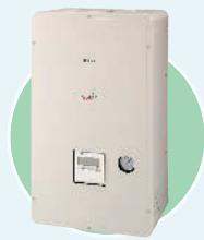
natural_image
Exterior view of a white rectangular electronic device with a small circular button and indicator lights (no visible text or symbols)Hydro Unit
HWS-803XWHM3-E
HWS-803XWHT6-E
HWS-803XWHD6-E
HWS-803XWHT9-E
HWS-1403XWHM3-E
HWS-1403XWHT6-E
HWS-1403XWHD6-E
HWS-1403XWHT9-E
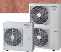
natural_image
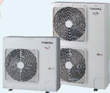
Three white industrial air conditioning units with fan blades, no visible text or symbols8 kw
11/14 kw
Outdoor Unit
HWS-803H-E
HWS-1103H-E
HWS-1403H-E
HWS-1103H8-E
HWS-1403H8-E
HWS-1603H8-E
HWS-1103H8R-E
HWS-1403H8R-E
HWS-1603H8R-E
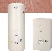
natural_image
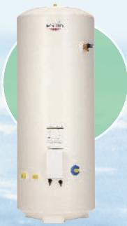
Exterior view of a beige cylindrical water tank with internal components and a green circular background (no visible text or symbols)Hot Water Cylinder
HWS-1501CSHM3-E
HWS-2101CSHM3-E
HWS-3001CSHM3-E
HWS-1501CSHM3-UK
HWS-2101CSHM3-UK
HWS-3001CSHM3-UK
Contents
- INTRODUCTION....2
- SYSTEM OVERVIEW....6
2-1. System Combination 7
2-2. Hydro Unit 7
2-3. Outdoor Unit....8
2-4. Hot Water Cylinder....8
2-5. Options....9
- SYSTEM SPECIFICATION....10
- HYDRO UNIT 12
4-1. Specification.... 12
4-2. Dimension 16
4-3. Piping Diagram 18
4-4. Wiring Diagram 20
4-5. Capacity Tables 26
4-6. Q-H characteristics of hydro unit ..... 56
4-7. Options....57
- OUTDOOR UNIT....59
5-1. Specification....60
5-2. Dimension 63
5-3. Piping Diagram 65
5-4. Wiring Diagram 66
5-5. Sound Data 71
5-6. Operation Range 76
- HOT WATER CYLINDER 78
6-1. Specification....79
6-2. Dimension 80
6-3. Piping Diagram 81
6-4. Wiring Diagram 83
- HYDRO UNIT INSTALLATION MANUAL 84
- OUTDOOR UNIT INSTALLATION MANUAL....132
- OWNER'S MANUAL....162
1. INTRODUCTION

natural_image
Sunset over calm sea with distant mountains and scattered clouds (no text or symbols)TOSHIBA AIRCONDITIONING
Advancing the eco-evolution
Air to water
Heat Pump System
World-leading energy efficiency — COP of 4.77*
Comfortable heating and hot water supply
Versatile installation and operation * 11 kW model
Welcome Estía to your home! Air-to-water Heat Pump System
Hot water cylinder
Hydro unit
Outdoor unit
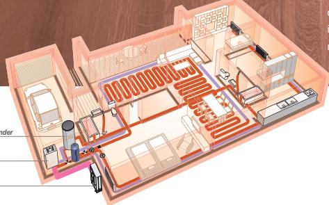
natural_image
Isometric interior layout of a hotel room with seating, air conditioning unit, and equipment (no text or labels visible)Introducing Toshiba's super-efficient space heating and hot water supply system for homes and businesses. Esta represents breakthrough thinking in intelligent heat pump and inverter technologies, by efficiently transferring ambient thermal heat from outside air to heat water indoors. Based on Toshiba's proven light commercial air conditioning system, the Super Digital Inverter, this innovative unit features DC twin rotary compressor, DC inverter and R410A refrigerant, providing the highest coefficient of performance (COP) in its class. This means more power from less energy consumption, and the ideal ecological and economical solution for your home.

8 kW
Outdoor unit
Hot water cylinder Hydro unit
Advantages
World-leading energy efficiency - COP of 4.77\*
With its best in class COP performance, Estía air to water heat pump system delivers more heating power with less energy consumption.
Estía uses high quality components and material which contribute to the overall savings in energy consumption.
With the Toshiba advanced inverter, Estía air to water heat pump system only delivers the heating capacity required; thus consuming only the necessary electricity.
The hot water temperature is also optimized thanks to Toshiba advanced control depending on the outside air temperature. The milder outside, the air-to-water systems automatically produces lower water temperature to anticipate decreased needs of space heating. The same control logic allows to anticipate as well increasing heating needs when weather conditions become extreme; this overall temperature management gives the best conditions of comfort.
All this saving has a positive impact on the personal electricity bill and the whole community by reducing the CO_2 emissions in the atmosphere.

*11kW model
Easy to install
Quick and easy to install. The hydro module unit can be placed safely in the most suitable place within the house.
There's no need for chimney or underground captors which require additional works on site. The compact outdoor unit can be placed anywhere outside the house or on a balcony, thanks to extensive piping options.

Environment conscious
The use of Toshiba Estía heat pump contribute to the reduction of global CO_2 emissions in the atmosphere and limit the use of fossil fuels or other non-renewable energy primary sources. Whenever required for maintenance purpose,

all the R410A refrigerant (non ozone depleting) can be completely sucked back to the outdoor unit through the powerful embedded Toshiba "pump down" operation.
One system, multiple solutions
Estía heat pump systems can be used in combination with different types of emitters: existing heating low temperature radiators, floor heating or fan coil units.

The right temperature at the right time
It can produce water at different temperatures for several applications simultaneously.

Toshiba Estía air to water heat pump system operates smoothly both with low outdoor air temperature down to -20 ^ in winter and up to 43 ^ in the summer season. The system has a unique anti-ice build-up protection embedded.

natural_image
Autumn tree with vibrant orange leaves against a pink and purple sky (no text or symbols)
natural_image
Baby in a pink bathtub holding a baby's face, no visible text or symbolsOne system, full combination flexibility
For new houses or refurbishment Estía heat pump offers a variety of combinations, some examples are shown below:
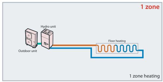
flowchart
graph LR
    A["Outdoor unit"] --> B["Hydro unit"]
    B --> C["Floor heating"]
    C --> D["1 zone heating"]
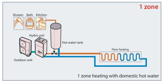
flowchart
graph LR
    A["Shower"] --> B["Hot water tank"]
    C["Bath"] --> B
    D["Kitchen"] --> B
    E["Hydro unit"] --> B
    F["Outdoor unit"] --> B
    B --> G["Floor heating"]
    style A fill:#f9f,stroke:#333
    style C fill:#f9f,stroke:#333
    style D fill:#f9f,stroke:#333
    style E fill:#f9f,stroke:#333
    style F fill:#f9f,stroke:#333
    style G fill:#ccf,stroke:#333
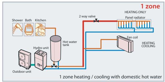
flowchart
graph LR
    A["Shower"] --> B["Hot water tank"]
    C["Bath"] --> B
    D["Kitchen"] --> B
    E["Outdoor unit"] --> B
    B --> F["2 way valve"]
    F --> G["HEATING ONLY Panel radiator"]
    G --> H["Fan coil"]
    H --> I["HEATING COOLING"]
    I --> J["1 zone heating / cooling with domestic hot water"]
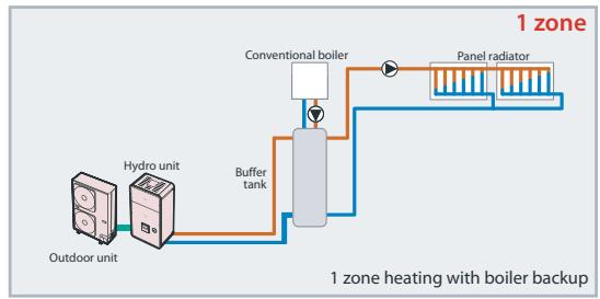
flowchart
graph LR
    A["Outdoor unit"] --> B["Hydro unit"]
    B --> C["Buffer tank"]
    C --> D["Conventional boiler"]
    D --> E["Panel radiator"]
    E --> F["1 zone heating with boiler backup"]
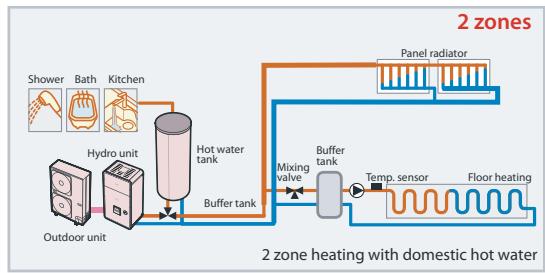
flowchart
graph LR
    A["Outdoor unit"] --> B["Hydro unit"]
    B --> C["Hot water tank"]
    C --> D["Buffer tank"]
    D --> E["Buffer tank"]
    E --> F["Panel radiator"]
    F --> G["Floor heating"]
    G --> H["Temp. sensor"]
    H --> I["Mixing valve"]
    I --> E
    style A fill:#f9f,stroke:#333
    style B fill:#f9f,stroke:#333
    style C fill:#ccf,stroke:#333
    style D fill:#ccf,stroke:#333
    style E fill:#cfc,stroke:#333
    style F fill:#fcc,stroke:#333
    style G fill:#fcc,stroke:#333
    style H fill:#fcc,stroke:#333
    style I fill:#fcc,stroke:#333
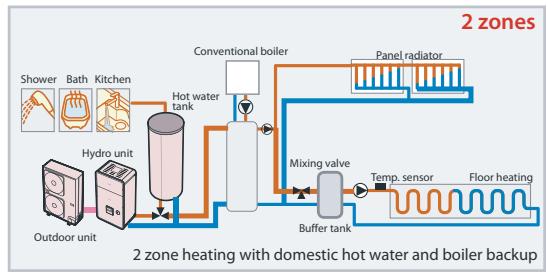
flowchart
graph LR
    A["Shower"] --> B["Hot water tank"]
    C["Bath"] --> B
    D["Kitchen"] --> B
    E["Outdoor unit"] --> F["Hydro unit"]
    B --> G["Conventional boiler"]
    G --> H["Panel radiator"]
    H --> I["Mixing valve"]
    I --> J["Buffer tank"]
    J --> K["Temp. sensor"]
    K --> L["Floor heating"]
    L --> M["2 zones"]
    style A fill:#f9f,stroke:#333
    style C fill:#f9f,stroke:#333
    style D fill:#f9f,stroke:#333
    style E fill:#f9f,stroke:#333
    style F fill:#f9f,stroke:#333
    style G fill:#ccf,stroke:#333
    style H fill:#ccf,stroke:#333
    style I fill:#cfc,stroke:#333
    style J fill:#cfc,stroke:#333
    style K fill:#cfc,stroke:#333
    style L fill:#cfc,stroke:#333
    style M fill:#cfc,stroke:#333
In existing dwellings already equipped with traditional gas or fuel boilers, Toshiba Estia air to water heat pump system can be combined with the existing heating system to cover exclusively and in an optimized way all the heating needs, all year round. Then, the boiler is only used as a back-up source during some extreme weather days of the winter.
The intelligent Toshiba control balances the energy source in the most efficient way.

natural_image
Two-panel image: left shows a water splash with bubbles, right shows a person washing dishes in a kitchen sink (no text or symbols visible)2. SYSTEM OVERVIEW
2-1. System Combination
Combination
| Outdoor Unit | ||||||||||
| Hydro Unit | HWS-803H-E | HWS-1103H-E | HWS-1403H-E | HWS-1103H8-E | HWS-1403H8-E | HWS-1603H8-E | HWS-1103H8R-E | HWS-1403H8R-E | HWS-1603H8R-E | Backup heater |
| HWS-803XWHM3-E | ● | - | - | - | - | - | - | - | - | ~, 3kW |
| HWS-803XWHT6-E | ● | - | - | - | - | - | - | - | - | 3N ~, 6kW |
| HWS-803XWHD6-E | ● | - | - | - | - | - | - | - | - | 3~, 6kW |
| HWS-803XWHT9-E | ● | - | - | - | - | - | - | - | 3N~, 9kW | |
| HWS-1403XWHM3-E | - | ● | ● | ● | ● | ● | ● | ● | ● | ~, 3kW |
| HWS-1403XWHT6-E | - | ● | ● | ● | ● | ● | ● | ● | ● | 3N~, 6kW |
| HWS-1403XWHD6-E | - | ● | ● | - | - | - | - | - | - | 3~, 6kW |
| HWS-1403XWHT9-E | - | ● | ● | ● | ● | ● | ● | ● | ● | 3N~, 9kW |
| Single phase model | 3 phase model | 3 phase with bottom plate heater | ||||||||
| Hot water cylinder | |||||||
| HWS-1501CSHM3-E | HWS-2101CSHM3-E | HWS-3001CSHM3-E | HWS-1501CSHM3-UK | HWS-2101CSHM3-UK | HWS-3001CSHM3-UK | ||
| Hydro unit | HWS-803XWHM3-E | ● | |||||
| HWS-803XWHT6-E | |||||||
| HWS-803XWHD6-E | |||||||
| HWS-803XWHT9-E | |||||||
| HWS-1403XWHM3-E | |||||||
| HWS-1403XWHT6-E | |||||||
| HWS-1403XWHD6-E | |||||||
| HWS-1403XWHT9-E | |||||||
2-2. Hydro Unit
80 class
| Hydro Unit | HWS-803XWHM3-E | HWS-803XWHT6-E | HWS-803XWHD6-E | HWS-803XWHT9-E | |
| Back up heater capacity | 3.0 | 6.0 | 9.0 | ||
| Power supply | for back up heater | 220-230V ~ 50Hz | 380-400V 3N~ 50Hz | 220-230V 3~ 50Hz | 380-400V 3N~ 50Hz |
| for hot water cylinder heater (option) | 220-230V ~ 50Hz | ||||
| Leaving water temperature | Heating (°C) | 20-55 | |||
| Cooling (°C) | 10-25 | ||||
112,140,160 class
| Hydro Unit | HWS-1403XWHM3-E | HWS-1403XWHT6-E | HWS-1403XWHD6-E | HWS-1403XWHT9-E | |
| Back up heater capacity | 3.0 | 6.0 | 9.0 | ||
| Power supply | for back up heater | 220-230V ~ 50Hz | 380-400V 3N~ 50Hz | 220-230V 3~ 50Hz | 380-400V 3N~ 50Hz |
| for hot water cylinder heater (option) | 220-230V ~ 50Hz | ||||
| Leaving water temperature | Heating (°C) | 20-55 | |||
| Cooling (°C) | 10-25 | ||||
2-3. Outdoor Unit
Single Phase model
| Outdoor unit | HWS-803H-E | HWS-1103H-E | HWS-1403H-E | ||
| Power supply | 220-230V ~ 50Hz | ||||
| Type | INVERTER | ||||
| Function | Heating & Cooling | ||||
| Heating | Capacity (kW) | 8.0 | 11.2 | 14.0 | |
| Input (kW) | 1.82 | 2.35 | 3.11 | ||
| COP (W/W) | 4.40 | 4.77 | 4.50 | ||
| Cooling | Capacity (kW) | 6.0 | 10.0 | 11.0 | |
| Input (kW) | 2.13 | 3.52 | 4.08 | ||
| EER (W/W) | 2.82 | 2.84 | 2.70 | ||
| Refrigerant | R410A | ||||
| Dimension | HxWxD (mm) | 890x900x320 | 1,340x900x320 | ||
3 Phase model
| Outdoor unit | with bottom plate heater | |||||||
| HWS-1103H8-E | HWS-1403H8-E | HWS-1603H8-E | HWS-1103H8R-E | HWS-1403H8R-E | HWS-1603H8R-E | |||
| Power supply | 380-400V 3N~50Hz | |||||||
| Type | INVERTER | |||||||
| Function | Heating & Cooling | |||||||
| Heating | Capacity (kW) | 11.2 | 14.0 | 16.0 | 11.2 | 14.0 | 16.0 | |
| Input (kW) | 2.39 | 3.21 | 3.72 | 2.39 | 3.21 | 3.72 | ||
| COP | 4.69 | 4.36 | 4.30 | 4.69 | 4.36 | 4.30 | ||
| Cooling | Capacity (kW) | 10.0 | 11.0 | 13.0 | 10.0 | 11.0 | 13.0 | |
| Input (kW) | 3.52 | 4.08 | 4.80 | 3.52 | 4.08 | 4.80 | ||
| EER | 2.84 | 2.70 | 2.71 | 2.84 | 2.70 | 2.71 | ||
| Refrigerant | R410A | |||||||
| Dimension | HxWxD (mm) | 1,340x900x320 | ||||||
| Bottom plate heater (W) | - | 75 | ||||||
2-4. Hot Water Cylinder
| Hot water cylinder (option) | HWS-1501CSHM3-EHWS-1501CSHM3-UK | HWS-2101CSHM3-EHWS-2101CSHM3-UK | HWS-3001CSHM3-EHWS-3001CSHM3-UK | |
| Water volume | litres | 150 | 210 | 300 |
| Max water temperature | (°C) | 75 | ||
| Electric heater | (kW) | 2.75 (230 V ~) | ||
| Height | (mm) | 1,090 | 1,474 | 2,040 |
| Diameter | (mm) | 550 | ||
| Material | Stainless steel | |||
2-5. Options
| No. | Part name | Model name | Application | Remarks |
| 1 | External output board | TCB-PCIN3E | Boiler-linked output, Alarm output | Up to two boards (according to applications) |
| Defrost signal output, compressor operation signal output | ||||
| 2 | External input board | TCB-PCMO3E | Cooling/heating thermostat input | Up to two boards (according to applications) |
| Forced-stop signal input | ||||
| 3 | Second Remote Controller | HWS-AMS11E | Wired Remote Controller for Room air temperature control |
3. SYSTEM SPECIFICATION
| Outdoor unit | HWS-803H-E | HWS-1103H-E | HWS-1403H-E | ||
| Hydro unit | HWS-803XWH**-E | HWS-1403XWH**-E | |||
| Rated Heating condition 1LWT=35°CdT=5deg | Capacity | kW | 8.0 | 11.2 | 14.0 |
| Power input | kW | 1.82 | 2.35 | 3.11 | |
| COP | W/W | 4.40 | 4.77 | 4.50 | |
| Rated water flow | l/min | 22.9 | 32.11 | 40.13 | |
| Rated Heating condition 2LWT=45°CdT=5deg | Capacity | kW | 8.0 | 11.2 | 14.0 |
| Power input | kW | 2.40 | 2.95 | 3.95 | |
| COP | W/W | 3.33 | 3.80 | 3.54 | |
| Rated water flow | l/min | 22.9 | 32.11 | 40.13 | |
| Rated Cooling condition 1LWT=7°CdT=5deg | Capacity | kW | 6.0 | 10.0 | 11.0 |
| Power input | kW | 2.13 | 3.52 | 4.08 | |
| EER | W/W | 2.82 | 2.84 | 2.70 | |
| Rated water flow rate | l/min | 17.2 | 28.67 | 31.53 | |
| Rated Cooling condition 2LWT=18°CdT=5deg | Capacity | kW | 6.0 | 10 | 11.0 |
| Power input | kW | 1.42 | 2.35 | 2.65 | |
| EER | W/W | 4.23 | 4.26 | 4.15 | |
| Rated water flow | l/min | 17.2 | 28.67 | 31.53 | |
| Power supply | 1~230V 50Hz | ||||
| Maximum current | A | 19.2 | 22.8 | 22.8 | |
* Rated condition capacity and power input are the data at rated compressor operating frequency.
* Power input does not include water pump power.
* Capacity and power input are measured in accordance with EN14511.
TO : Outdoor temperature (°C)
LWT : Leaving water temperature (°C)
dT : Delta temperature (deg)
Leaving water temperature - return water temperature (Heating)
Return water temperature - leaving water temperature (Cooling)
| Outdoor unit | HWS-1103H8-E | HWS-1403H8-E | HWS-1603H8-E | ||
| Hydro unit | HWS-1403XWH**-E | HWS-1403XWH**-E | HWS-1403XWH**-E | ||
| Rated Heating condition 1LWT=35°CdT=5deg | Capacity | kW | 11.2 | 14.0 | 16.0 |
| Power input | kW | 2.39 | 3.21 | 3.72 | |
| COP | W/W | 4.69 | 4.36 | 4.30 | |
| Rated water flow rate | l/min | 32.11 | 40.13 | 45.70 | |
| Rated Heating condition 2LWT=45°CdT=5deg | Capacity | kW | 11.2 | 14.0 | 16.0 |
| Power input | kW | 3.19 | 4.12 | 4.88 | |
| COP | W/W | 3.51 | 3.40 | 3.28 | |
| Rated water flow rate | l/min | 32.11 | 40.13 | 45.70 | |
| Rated Cooling condition 1LWT=7°CdT=5deg | Capacity | kW | 10.0 | 11.0 | 13.0 |
| Power input | kW | 3.52 | 4.08 | 4.80 | |
| EER | W/W | 2.84 | 2.70 | 2.71 | |
| Rated water flow rate | l/min | 28.67 | 31.53 | 37.20 | |
| Rated Cooling condition 2LWT=18°CdT=5deg | Capacity | kW | 10.0 | 11.0 | 13.0 |
| Power input | kW | 2.14 | 2.43 | 3.08 | |
| EER | W/W | 4.67 | 4.53 | 4.22 | |
| Rated water flow rate | l/min | 28.67 | 31.53 | 37.20 | |
| Power supply | 3N ~ 380-400V 50Hz | ||||
| Maximum current | 14.6 | 14.6 | 14.6 | ||
4. HYDRO UNIT
4-1. Specification
4-1-1. Hydro unit specifications
| Hydro unit | HWS-803XWHM3-E | HWS-803XWHT6-E | HWS-803XWHD6-E | HWS-803XWHT9-E | ||
| Back up heater | back up heater | kW | 3 | 6 | 6 | 9 |
| Power supply | 1 ~ 220-230V 50Hz | 3N~ 380-400V 50Hz | 3~ 220-230V 50Hz | 3N~ 380-400V 50Hz | ||
| Maximum current | A | 13 | 13 (13A*2P) | 23A | 13 (13A*3P) | |
| Hot water cylinder heater* | Power supply | 1 ~ 220-230V 50Hz | ||||
| Maximum current | A | 12.0 | ||||
| Appearance | Color | Silky shade (Muncel 1Y8.5-0.5) | ||||
| Material | PCM | |||||
| Outer dimension | Height | mm | 925 | |||
| Width | mm | 525 | ||||
| Depth | mm | 355 | ||||
| Unit weight | kg | 50 | ||||
| Packing dimension | Height | mm | 1070 | |||
| Width | mm | 608 | ||||
| Depth | mm | 436 | ||||
| Total weight | Unit and packing | kg | 54 | |||
| Heat exchanger | Type | Brazed plate | ||||
| Water volume | litres | 0.67 | ||||
| Minimum flow rate | l/min | 13 | ||||
| Water pump | Power input | W | 125 / 95 / 65 | |||
| Delivery head | m | 6.5 / 6.1 / 4.5 | ||||
| Expansion vessel | Volume | litres | 12 | |||
| Initial pressure | MPa(bar) | 0.1 (1) | ||||
| Pressure relief valve | Operating pressure | MPa(bar) | 0.3 (3) | |||
| Sound pressure level | dBA | 29 | ||||
| Operation water temp. | Heating | °C | 20~55 | |||
| Cooling | °C | 10~25 | ||||
| Water pipe | Outlet | mm | 34.92 | |||
| Inlet | mm | 34.92 | ||||
| Refrigerant pipe | Gas | mm | 15.9 | |||
| Liquid | mm | 9.5 | ||||
| Drain port | mm | 16.0 inner diameter for drain hose | ||||
| Note | * The electric heater, incorporated in the hot water cylinder, requires separate supply to hydro unit. | |||||
| Hydro unit | HWS-1403XWHM3-E | HWS-1403XWHT6-E | HWS-1403XWHD6-E | HWS-1403XWHT9-E | ||
| Back up heater | back up heater | kW | 3 | 6 | 6 | 9 |
| Power supply | 1 ~ 220-230V 50Hz | 3N~ 380-400V 50Hz | 3~ 220-230V 50Hz | 3N~ 380-400V 50Hz | ||
| Maximum current | A | 13 | 13 (13A*2P) | 13 (13A*2P) | 13 (13A*3P) | |
| Hot water cylinder heater* | Power supply | 1 ~ 220-230V 50Hz | ||||
| Maximum current | A | 12.0 | ||||
| Appearance | Color | Silky shade (Muncel 1Y8.5-0.5) | ||||
| Material | PCM | |||||
| Outer dimension | Height | mm | 925 | |||
| Width | mm | 525 | ||||
| Depth | mm | 355 | ||||
| Unit weight | kg | 54 | ||||
| Packing dimension | Height | mm | 1070 | |||
| Width | mm | 608 | ||||
| Depth | mm | 436 | ||||
| Total weight | Unit and packing | kg | 58 | |||
| Heat exchanger | Type | Brazed plate | ||||
| Water volume | litres | 1.18 | ||||
| Minimum flow rate | l/min | 17.5 | ||||
| Water pump | Power input | W | 190 / 180 / 135 | |||
| Delivery head | m | 8.3 / 8.1 / 7.2 | ||||
| Expansion vessel | Volume | litres | 12 | |||
| Initial pressure | MPa(bar) | 0.1 (1) | ||||
| Pressure relief valve | Operating pressure | MPa(bar) | 0.3 (3) | |||
| Sound pressure level | dBA | 29 | ||||
| Operation water temp. | Heating | °C | 20~55 | |||
| Cooling | °C | 10~25 | ||||
| Water pipe | Outlet | mm | 34.92 | |||
| Inlet | mm | 34.92 | ||||
| Refrigerant pipe | Gas | mm | 15.9 | |||
| Liquid | mm | 9.5 | ||||
| Drain port | mm | 16.0 inner diameter for drain hose | ||||
| Note | * The electric heater, incorporated in the hot water cylinder, requires separate supply to hydro unit. | |||||
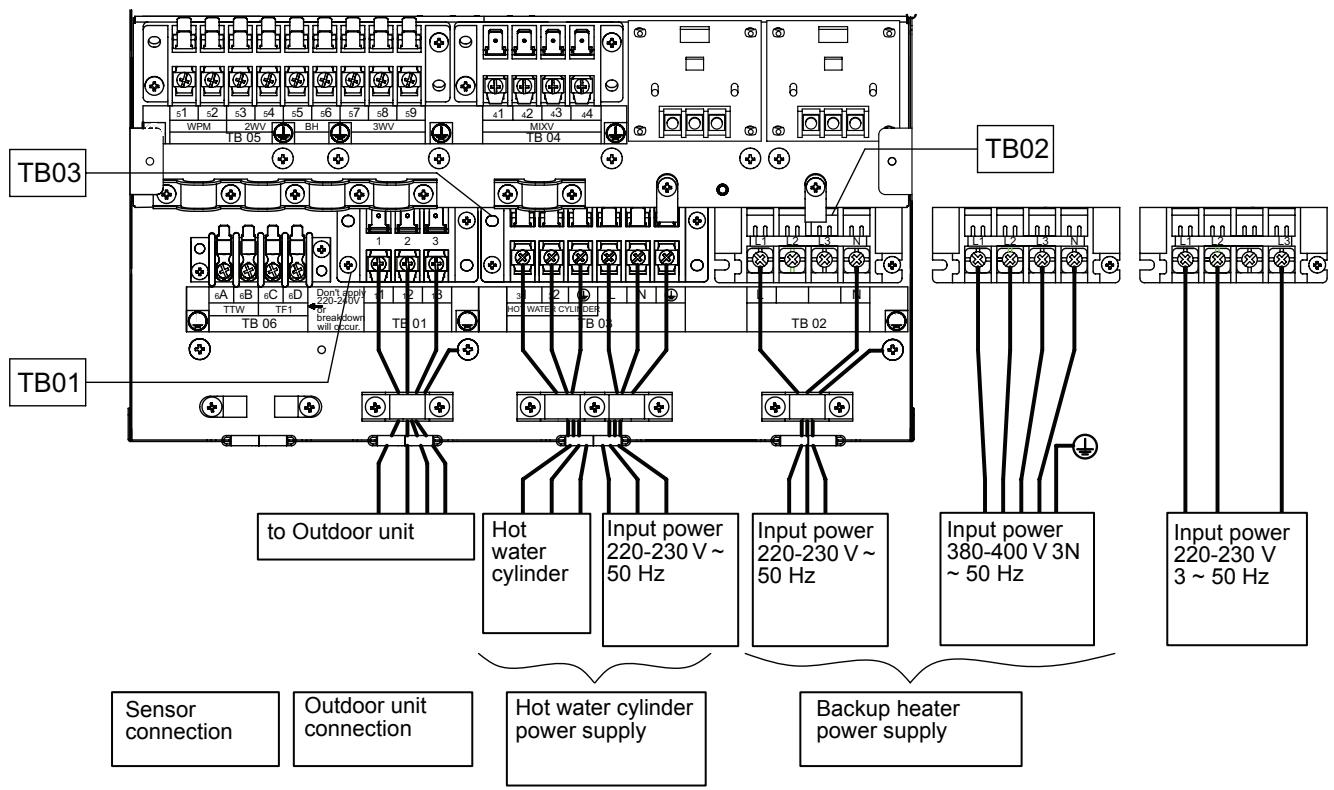
4-1-2. Power Wiring specifications
| Description | Model name HWS- | POWER SUPPLY | Maximum current | Installation fuse rating | Power wire | Connection destination | ||
| Outdoor unit power | Power input | 1403H-E | 220-230 V ~ 50 Hz | 22.8A | 25 A | 2.5 mm^2 or more | L, N | |
| 1103H-E | 220-230 V ~ 50 Hz | 22.8A | 25 A | 2.5 mm^2 or more | ||||
| 803H-E | 220-230 V ~ 50 Hz | 19.2A | 20A | 2.5 mm^2 or more | ||||
| 1603H8-E, 1603H8R-E | 380-400V 3N~ 50Hz | 14.6A | 16A | 2.5 mm^2 or more | L1, L2, L3, N | |||
| 1403H8-E, 1403H8R-E | 380-400V 3N~ 50Hz | 14.6A | 16A | 2.5 mm^2 or more | ||||
| 1103H8-E, 1103H8R-E | 380-400V 3N~ 50Hz | 14.6A | 16A | 2.5 mm^2 or more | ||||
| Hydro inlet heater power | Power input for backup heater | 1403XWHM3-E | 220-230V ~ 50Hz | 13A | 16A | 1.5 mm^2 or more | L, N | TB02 |
| 1403XWHD6-E | 220-230V 3~ 50Hz | 23A | 25A | 2.5 mm^2 or more | L1, L2, L3 | |||
| 1403XWHT6-E | 380-400V 3N~ 50Hz | 13A(13A x 2P) | 16A | 1.5 mm^2 or more | L1, L2, L3, N | |||
| 1403XWHT9-E | 380-400V 3N~ 50Hz | 13A(13A x 3P) | 16A | 1.5 mm^2 or more | ||||
| 803XWHM3-E | 220-230V ~ 50Hz | 13A | 16A | 1.5 mm^2 or more | L, N | |||
| 803XWHD6-E | 220-230V 3~ 50Hz | 23A | 25A | 2.5 mm^2 or more | L1, L2, L3 | |||
| 803XWHT6-E | 380-400V 3N~ 50Hz | 13A(13A x 2P) | 16A | 1.5 mm^2 or more | L1, L2, L3, N | |||
| 803XWHT9-E | 380-400V 3N~ 50Hz | 13A(13A x 3P) | 16A | 1.5 mm^2 or more | ||||
| Power input for cylinder heater | 220-230V ~ 50Hz | 12A | 16A | 1.5 mm^2 or more | L, N | TB03 | ||
| Outdoor-Hydro unit | Connection | 1.5 mm^2 or more | 1, 2, 3 | |||||
| Hydro -Cylinder | Connection | 1.5 mm^2 or more | 1, 2 | TB03 | ||||
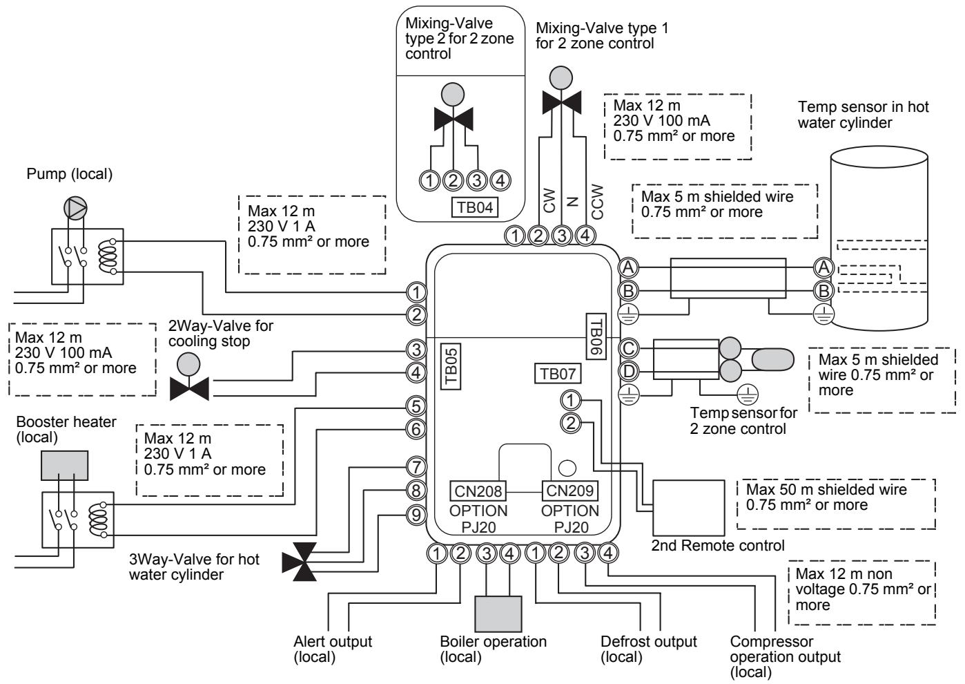
4-1-3. External Device specifications
| Power | Maximum current | Type | |
| Motorized 3-way valve (for hot water) | AC 230 V | 100 mA | Spring return typeNote: 3-wire SPST and SPDT type can be used by changing the DPSW 13-1. |
| Motorized 2-way valve (for cooling) | AC 230 V | 100 mA | spring return type (normally open) |
| Motorized mixing valve type 1 (for 2-zone) | AC 230 V | 100 mA | 60 sec 90°. SPDT typeNote: SPST and 20 to 240 sec type can be used by changing the function code. |
4-1-4. External Device Wiring specifications
| Description | Line spec | Maximum current | Maximum length | Cable size | Connection destination |
| 3-way valve control | 2 line or 3 line | 100 mA | 12 m | 0.75 mm^2 or more | 7, 8, 9 (TB05) |
| Mixing valve control | 3 line | 100 mA | 12 m | 0.75 mm^2 or more | 1, 2, 3 or 2, 3, 4 (TB04) |
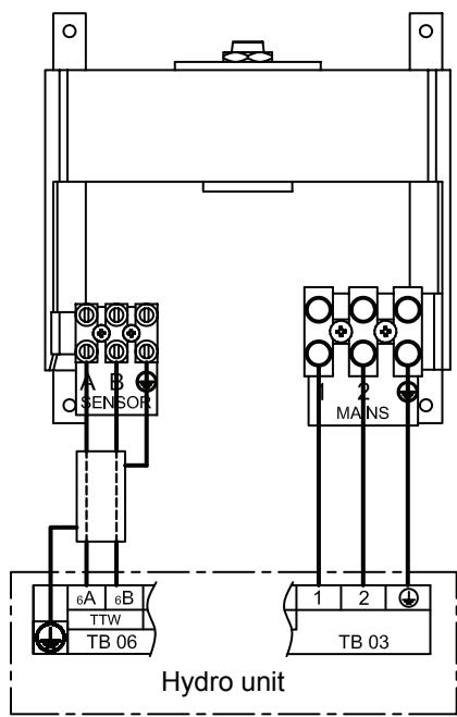
| 2-zone thermo sensor | 2 line | 100 mA | 5 m | 0.75 mm^2 or more | ©, © (TB06) |
| Cylinder thermo sensor | 2+GND(shield wire) | 100 mA | 5 m | 0.75 mm^2 or more | A, B (TB06) |
| Second remote controller | 2 line | 50 mA | 50 m | 0.75 mm^2 or more | 1, 2 (TB07) |
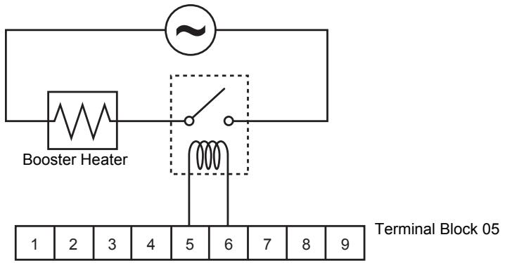
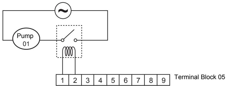
4-1-5. External Output specifications
| Description | Output | Maximum current | Max voltage | Maximum length | |
| External pump No.1 | AC230V | 1 A | - | 12 m | |
| External boost heater | AC230V | 1 A | - | 12 m | Output as required when outdoor air temperature is -20°C or less |
| Boiler control | Non-voltage contacts | 0.5 A | AC230 V | 12 m | Output as required when outdoor air temperature is -10°C or less |
| 1 A | DC24 V | 12 m | |||
| ALARM Output | Non-voltage contacts | 0.5 A | AC230 V | 12 m | |
| 1 A | DC24 V | 12 m | |||
| Compressor Operation Output | Non-voltage contacts | 0.5 A | AC230 V | 12 m | |
| 1 A | DC24 V | 12 m | |||
| Defrost Output | Non-voltage contacts | 0.5 A | AC230 V | 12 m | |
| 1 A | DC24 V | 12 m |
4-1-6. External Input specifications
| Description | Input | Maximum length |
| Emergency stop control | Non-voltage | 12 m |
| Cooling thermostat input | Non-voltage | 12 m |
| Heating thermostat input | Non-voltage | 12 m |
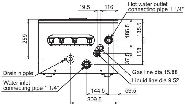
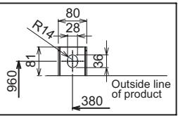
4-2. Dimension
▼Hydro unit
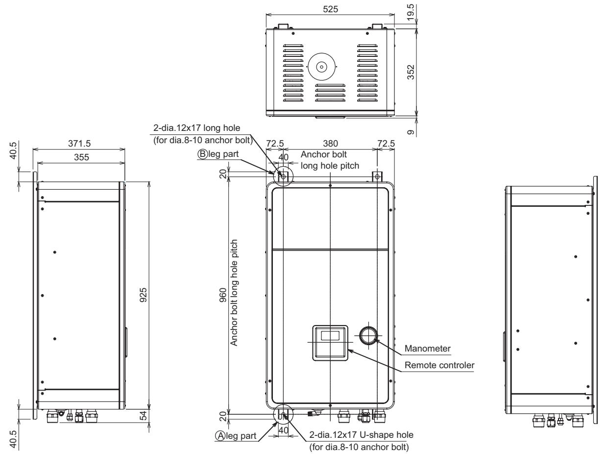
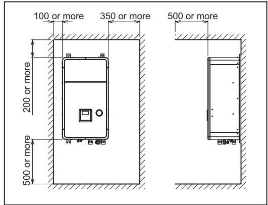
Service space
Detailed Ⓐ leg part
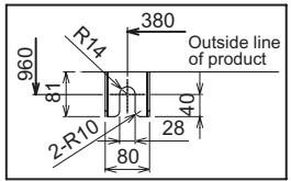
Detailed Ⓑ leg part
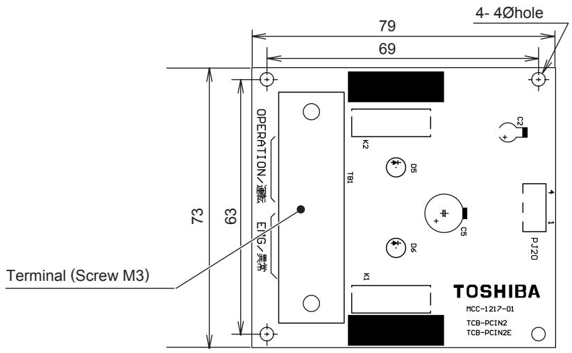
▼External output board (TCB-PCIN3E)
Size (mm) : H22 x L73 x W79
Weight (g) : 57
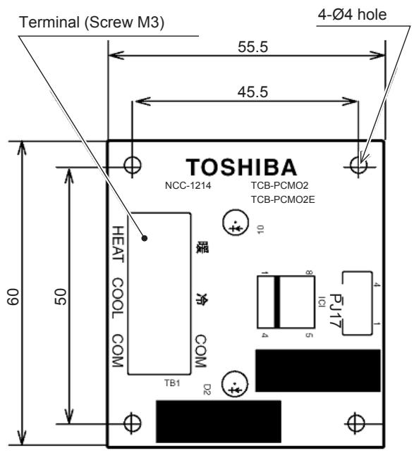
▼External input board (TCB-PCMO3E)
Size (mm) : H18 x L55.5 x W60
Weight (g) : 20
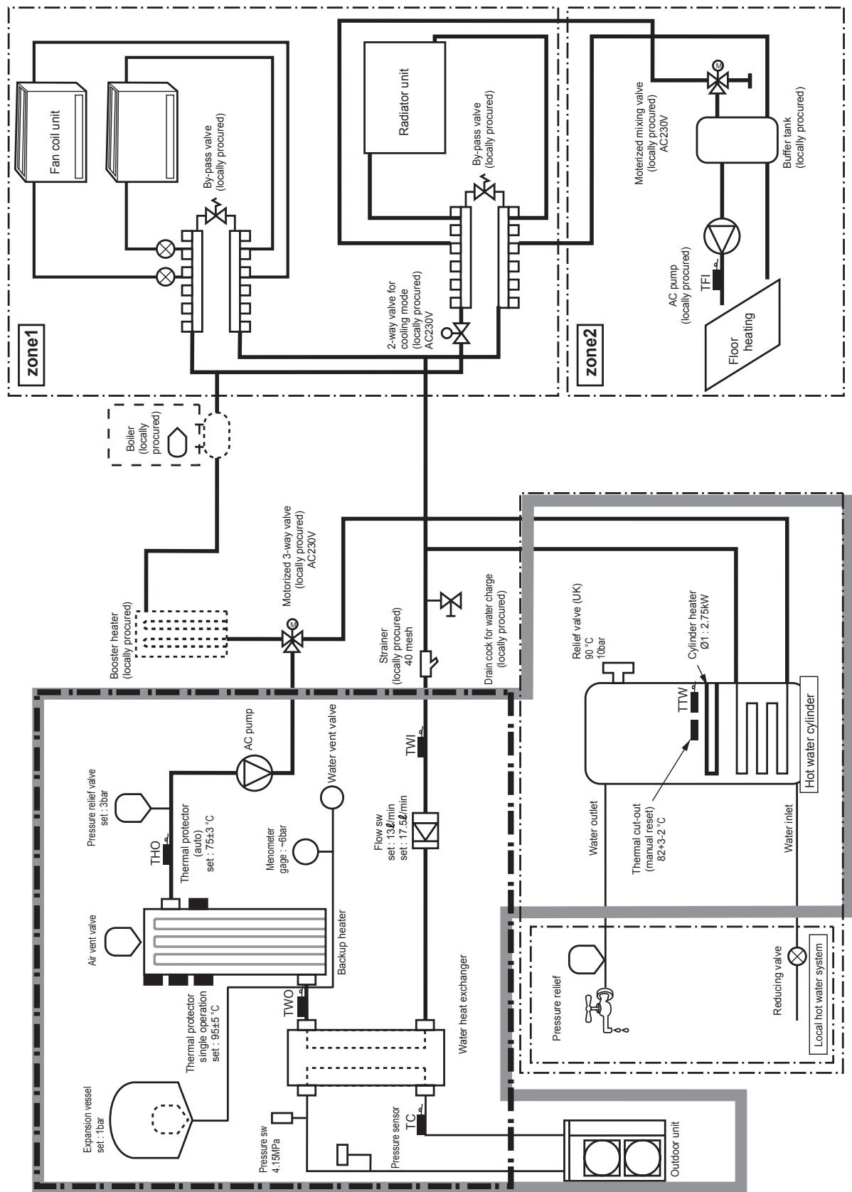
4-3. Piping Diagram
Water system diagram
flowchart
graph TD
    subgraph zone1
        A["Expansion vessel set: 1bar"] --> B["Thermal protector single operation set: 95±5°C"]
        C["Pressure sw 4.15MPa"] --> D["TWO"]
        E["Pressure sensor TC"] --> F["Water heat exchanger"]
        G["Water inlet"] --> H["Hot water cylinder"]
        I["Reducing valve"] --> J["Water outlet"]
        K["Pressure relief"] --> L["Thermal cut-out (manual reset) 82+3-2°C"]
        M["Booster heater (locally procured)"] --> N["Motorized 3-way valve (locally procured) AC230V"]
        O["Strainer (locally procured) 40 mesh"] --> P["Drain cock for water charge (locally procured)"]
        Q["Cylinder heater Ø1: 2.75kW"] --> R["Relief valve (UK) 90°C 10bar"]
        S["Boiler (locally procured)"] --> T["Booster heater (locally procured)"]
        U["Fan coil unit"] --> V["Boiler (locally procured)"]
        W["By-pass valve (locally procured)"] --> X["Motorized 3-way valve (locally procured) AC230V"]
        Y["Radiator unit"] --> Z["2-way valve for cooling mode (locally procured) AC230V"]
        AA["Buffer tank (locally procured)"] --> AB["AC pump (locally procured)"]
        AC["Moterized mixing valve (locally procured) AC230V"] --> AD["AC pump (locally procured)"]
        AE["Floor heating"] --> AF["TFI"]
    end
    subgraph zone2
        AG["Outdoor unit"] --> AH["Water outlet"]
        AI["Pressure relief"] --> AJ["Thermal cut-out (manual reset) 82+3-2°C"]
        AK["Reducing valve"] --> AL["Water inlet"]
        AM["Water inlet"] --> AN["Hot water cylinder"]
        AO["Water outlet"] --> AP["Cylinder heater Ø1: 2.75kW"]
        AQ["Water inlet"] --> AR["TTW"]
        AS["Water outlet"] --> AT["TWO"]
        AU["Pressure sensor"] --> AV["TWO"]
        AW["Pressure sensor"] --> AX["TWO"]
        AY["Bowder heater"] --> AZ["AC pump (locally procured)"]
        BA["AC pump (locally procured)"] --> BB["AC pump (locally procured)"]
    end
Refrigeration cycle system diagram
Hydro unit
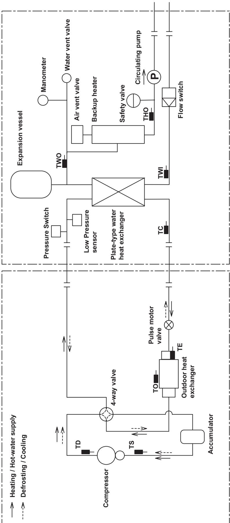
flowchart
graph TD
    A["Heating / Hot-water supply"] --> B["Compressor"]
    C["Defrosting / Cooling"] --> D["Accumulator"]
    B --> E["4-way valve"]
    D --> F["TO"]
    D --> G["TS"]
    D --> H["TO"]
    D --> I["TE"]
    D --> J["Outdoor heat exchanger"]
    J --> K["Pulse motor valve"]
    K --> L["Pulse motor valve"]
    L --> M["4-way valve"]
    N["Expansion vessel"] --> O["Pressure Switch"]
    O --> P["Low Pressure sensor"]
    P --> Q["Plate-type water heat exchanger"]
    Q --> R["TWO"]
    Q --> S["Air vent valve"]
    Q --> T["Backup heater"]
    Q --> U["Safety valve"]
    Q --> V["THO"]
    Q --> W["Circulating pump"]
    Q --> X["Flow switch"]
    Y["Manometer"] --> Z["Water vent valve"]
    style A fill:#f9f,stroke:#333
    style C fill:#f9f,stroke:#333
    style N fill:#ccf,stroke:#333
    style Y fill:#ccf,stroke:#333
Outdoor unit
→ Heating / Hot-water supply
----> Defrosting / Cooling
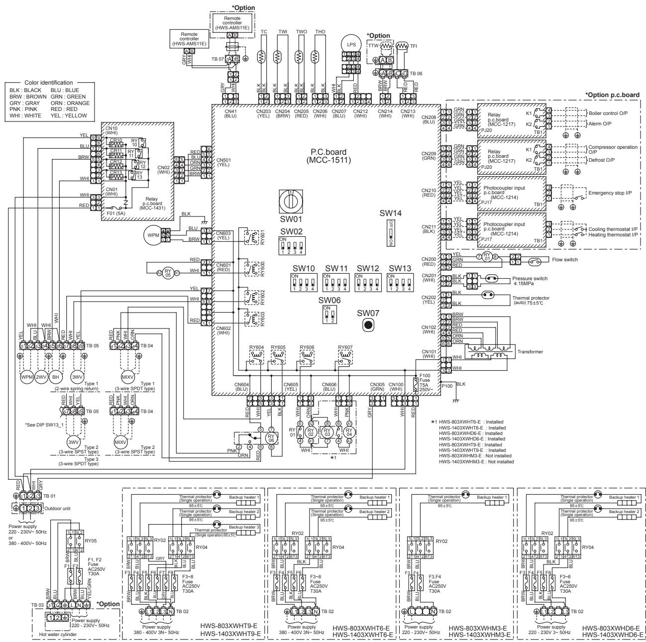
4-4. Wiring Diagram
4-4-1. Hydro unit
flowchart
graph TD
    subgraph Power Supply
        A["Power supply 220-230V~50Hz or 380-400V~50Hz"] --> B["Red"]
        B --> C["Type 1 (2-wire spring return)"]
        C --> D["Type 2 (3-wire SPDT type)"]
        D --> E["Type 3 (3-wire SPDT type)"]
        E --> F["Red"]
        F --> G["Type 1 (3-wire SPDT type)"]
        G --> H["Type 2 (3-wire SPDT type)"]
        H --> I["Red"]
        I --> J["Type 1 (3-wire SPDT type)"]
        J --> K["Type 2 (3-wire SPDT type)"]
        K --> L["Red"]
        L --> M["Type 1 (3-wire SPDT type)"]
        M --> N["Type 2 (3-wire SPDT type)"]
        N --> O["Red"]
        O --> P["Type 1 (3-wire SPDT type)"]
        P --> Q["Type 2 (3-wire SPDT type)"]
        Q --> R["Red"]
        R --> S["Type 1 (3-wire SPDT type)"]
        S --> T["Type 2 (3-wire SPDT type)"]
        T --> U["Red"]
        U --> V["Type 1 (3-wire SPDT type)"]
        V --> W["Type 2 (3-wire SPDT type)"]
        W --> X["Red"]
        X --> Y["Type 1 (3-wire SPDT type)"]
        Y --> Z["Type 2 (3-wire SPDT type)"]
        Z --> AA["Red"]
        AA --> AB["Type 1 (3-wire SPDT type)"]
        AB --> AC["Type 2 (3-wire SPDT type)"]
        AC --> AD["Red"]
        AD --> AE["Type 1 (3-wire SPDT type)"]
        AE --> AF["Type 2 (3-wire SPDT type)"]
        AF --> AG["Red"]
        AG --> AH["Type 1 (3-wire SPDT type)"]
        AH --> AI["Type 2 (3-wire SPDT type)"]
        AI --> AJ["Red"]
        AJ --> AK["Type 1 (3-wire SPDT type)"]
        AK --> AL["Type 2 (3-wire SPDT type)"]
        AL --> AM["Red"]
        AM --> AN["Type 1 (3-wire SPDT type)"]
        AN --> AO["Type 2 (3-wire SPDT type)"]
        AO --> AP["Red"]
        AP --> AQ["Type 1 (3-wire SPDT type)"]
        AQ --> AR["Type 2 (3-wire SPDT type)"]
        AR --> AS["Red"]
        AS --> AT["Type 1 (3-wire SPDT type)"]
        AT --> AU["Type 2 (3-wire SPDT type)"]
        AU --> AV["Red"]
        AV --> AW["Type 1 (3-wire SPDT type)"]
        AW --> AX["Type 2 (3-wire SPDT type)"]
        AX --> AY["Red"]
        AY --> AZ["Type 1 (3-wire SPDT type)"]
        AZ --> BA["Type 2 (3-wire SPDT type)"]
        BA --> BB["Red"]
        BB --> BC["Type 1 (3-wire SPDT type)"]
        BC --> BD["Type 2 (3-wire SPDT type)"]
        BD --> BE["Red"]
        BE --> BF["Type 1 (3-wire SPDT type)"]
        BF --> BG["Type 2 (3-wire SPDT type)"]
        BG --> BH["Red"]
        BH --> BI["Type 1 (3-wire SPDT type)"]
        BI --> BJ["Type 2 (3-wire SPDT type)"]
        BJ --> BK["Red"]
        BK --> BLA["Type 1 (3-wire SPDT type)"]
        BLA --> BM["Type 2 (3-wire SPDT type)"]
        BM --> BN["Red"]
        BN --> BO["WPM"]
        BO --> BP["WHI"]
        BP --> BQ["WBI"]
        BQ --> BR["HI"]
        BR --> BS["PW"]
    end

    subgraph Power Supply
        C
        D
    end

    subgraph Control Identification
        E
    end

    subgraph P.C. Board
            F
    end

    subgraph SW01
            G
    end

    subgraph SW02
            H
    end

    subgraph SW06
            I
    end

    subgraph SW07
            J
    end

    subgraph Thermal Protector
            K
    end

    subgraph Power Supply
            L
    end

    subgraph HWS-803XWHT9-E
            M
    end

    subgraph HWS-803XWHT6-E
            N
    end

    subgraph Power Supply
            O
    end

    subgraph HWS-803XWHM3-E
            P
    end

    subgraph Power Supply
            Q
    end

    subgraph HWS-803XWHD6-E
            R
    end
| Symbol | Parts name | Symbol | Parts name |
| WPM | Water pump motor | TC | Water heat exchanger temperature sensor |
| 3WV | 3-way valve (locally procured) | TWI | Water inlet temperature sensor |
| 2WV | 2-way valve (locally procured) | TWO | Water outlet temperature sensor |
| MIXV | Mixing valve (locally procured) | THO | Heater outlet temperature sensor |
| BH | Booster heater | TTW | Hot water cylinder temperature sensor |
| RY01~RY06 | Relay01~Relay06 | TFI | Floor heating inlet temperature sensor |
| LPS | Low pressure sensor | TB | Terminal block |
| Backup heater1, 2, 3 | Heater AC230V, 3kW |
- The one-dot chain line indicates wiring at the local site, and the dashed line indicates accessories sold separately and service wires, respectively.
- , and indicates the terminal board and the numbers indicate the terminal numbers.
- indicates P.C. board.
* Be sure to fix the electric parts cover surely with screws. (Otherwise water enters into the box resulting in malfunction.)
4-4-2. Power line
Electrical connection to hydro unit
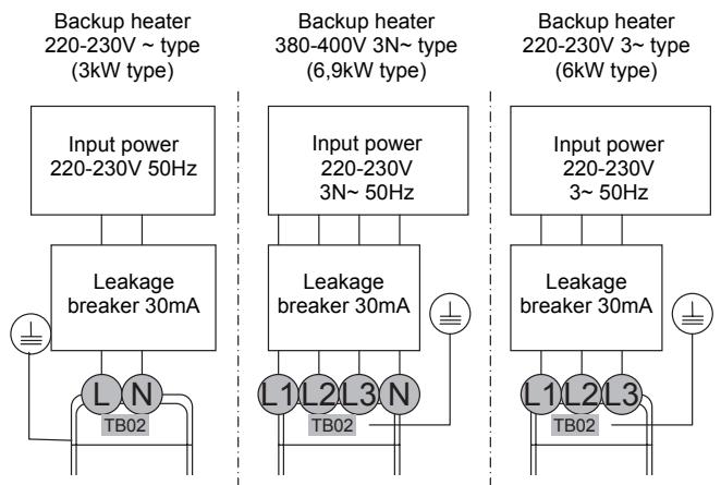
flowchart
graph TD
    A["Input power 220-230V 50Hz"] --> B["Leakage breaker 30mA"]
    C["Input power 220-230V 3N~ 50Hz"] --> D["Leakage breaker 30mA"]
    E["Input power 220-230V 3~ 50Hz"] --> F["Leakage breaker 30mA"]
    G["Input power 220-230V 3~ 50Hz"] --> H["Leakage breaker 30mA"]
    I["Input power 220-230V 3~ 50Hz"] --> J["Leakage breaker 30mA"]
    K["Input power 220-230V 3~ 50Hz"] --> L["Leakage breaker 30mA"]
    M["Input power 220-230V 3~ 50Hz"] --> N["Leakage breaker 30mA"]
    O["Input power 220-230V 3~ 50Hz"] --> P["Leakage breaker 30mA"]
    Q["Input power 220-230V 3~ 50Hz"] --> R["Leakage breaker 30mA"]
    S["Input power 220-230V 3~ 50Hz"] --> T["Leakage breaker 30mA"]
    U["Input power 220-230V 3~ 50Hz"] --> V["Leakage breaker 30mA"]
    W["Input power 220-230V 3~ 50Hz"] --> X["Leakage breaker 30mA"]
    Y["Input power 220-230V 3~ 50Hz"] --> Z["Leakage breaker 30mA"]
    AA["Input power 220-230V 3~ 50Hz"] --> AB["Leakage breaker 30mA"]
    AC["Input power 220-230V 3~ 50Hz"] --> AD["Leakage breaker 30mA"]
    AE["Input power 220-230V 3~ 50Hz"] --> AF["Leakage breaker 30mA"]
    AG["Input power 220-230V 3~ 50Hz"] --> AH["Leakage breaker 30mA"]
    AI["Input power 220-230V 3~ 50Hz"] --> AJ["Leakage breaker 30mA"]
    AK["Input power 220-230V 3~ 50Hz"] --> AL["Leakage breaker 30mA"]
    AM["Input power 220-230V 3~ 50Hz"] --> AN["Leakage breaker 30mA"]
    AO["Input power 220-230V 3~ 50Hz"] --> AP["Leakage breaker 30mA"]
    AQ["Input power 220-230V 3~ 50Hz"] --> AR["Leakage breaker 30mA"]
    AS["Input power 220-230V 3~ 50Hz"] --> AT["Leakage breaker 30mA"]
    AU["Input power 220-230V 3~ 50Hz"] --> AV["Leakage breaker 30mA"]
    AW["Input power 220-230V 3~ 50Hz"] --> AX["Leakage breaker 30mA"]
    AY["Input power 220-230V 50Hz"] --> AZ["L N TB02"]
    BA["Input power 220-230V 50Hz"] --> BB["L N TB02"]
    BC["Input power 220-230V 50Hz"] --> BD["L N TB02"]
    BE["Input power 220-230V 50Hz"] --> BF["L N TB02"]
    BG["Input power 220-230V 50Hz"] --> BH["L N TB02"]
    BI["Input power 220-230V 50Hz"] --> BJ["L N TB02"]
    BK["Input power 220-230V 50Hz"] --> BL["L N TB02"]
    BM["Input power 220-230V 50Hz"] --> BN["L N TB02"]
    BO["Input power 220-230V 50Hz"] --> BP["L N TB02"]
    BQ["Input power 220-230V 5N~ type (6.9kW type)"] --> BR["L1 L1 TB02"]
    BS["Input power 220-230V 5N~ type (6.9kW type)"] --> BT["L1 L1 TB02"]
    BU["Input power 220-230V 5N~ type (6.9kW type)"] --> BV["L1 L1 TB02"]
    BW["Input power 220-230V 5N~ type (6.9kW type)"] --> BX["L1 L1 TB02"]
    BY["Input power 220-230V 5N~ type (6.9kW type)"] --> BZ["L1 L1 TB02"]
    CA["Input power 220-230V 5N~ type (6.9kW type)"] --> CB["L1 L1 TB02"]
    CC["Input power 220-230V 5N~ type (6.9kW type)"] --> CD["L1 L1 TB02"]
    DD["Input power 220-23O ~ type (6kW type)"] --> DP["L1 L1 TB02"]
    DP --> DPB["L1 L1 TB1 TB1 TB1 TB1 TB1 TB1 TB1 TB1 TB1 TB1 TB1 TB1 TB1 TB1 TB1 TB1 TB1 TB1 TB1 TB1 TB1 TB1 TB1 TB1 TB1 TB1 TB1 TB1 TB1 TB1 TB1 TB1 TB1 TB1 TB1 TB1 TB1 TB1 TB1 TB1 TB1 TB1 TB1 TB1 TB1 TB1 TB1 TB1 TB1 TB1 TF"]
Outdoor unit to hydro unit electrical connection
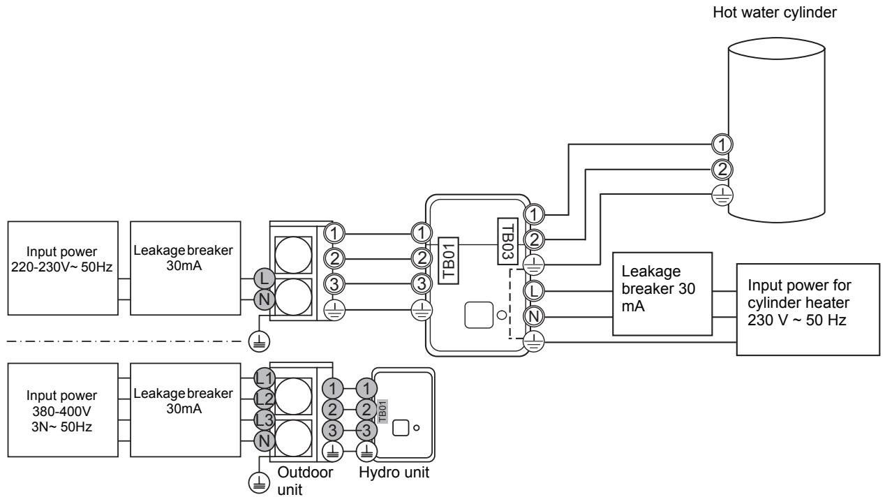
flowchart
graph LR
    A["Input power 220-230V~50Hz"] --> B["Leakage breaker 30mA"]
    C["Input power 380-400V 3N~50Hz"] --> D["Leakage breaker 30mA"]
    B --> E["TB01"]
    D --> F["TB01"]
    E --> G["TB03"]
    F --> G
    G --> H["Leakage breaker 30 mA"]
    H --> I["Hot water cylinder"]
    J["Outdoor unit"] --> K["Hydro unit"]
    L["Input power for cylinder heater 230 V~50 Hz"] --> M["Leakage breaker 30 mA"]
    N["Input power 220-230V~50Hz"] --> O["Leakage breaker 30mA"]
    P["Input power 380-400V 3N~50Hz"] --> Q["Leakage breaker 30mA"]
    R["TB01"] --> S["TB03"]
    T["Ground"] --> U["TB01"]
4-4-3. Control line
flowchart
graph TD
    A["Pump (local)"] --> B["Booster heater (local)"]
    B --> C["2Way-Valve for cooling stop"]
    C --> D["3Way-Valve for hot water cylinder"]
    D --> E["Max 12 m 230 V 100 mA 0.75 mm² or more"]
    E --> F["Max 12 m 230 V 1 A 0.75 mm² or more"]
    F --> G["Max 12 m 230 V 100 mA 0.75 mm² or more"]
    G --> H["Max 12 m 230 V 1 A"]
    H --> I["Max 12 m 230 V 100 mA"]
    I --> J["Max 12 m 230 V 1 A"]
    J --> K["Max 12 m 230 V 100 mA"]
    K --> L["Max 12 m 230 V 1 A"]
    L --> M["Max 12 m 230 V 100 mA"]
    M --> N["Max 12 m 230 V 1 A"]
    N --> O["Max 12 m 230 V 100 mA"]
    O --> P["Max 12 m 230 V 1 A"]
    P --> Q["Max 12 m 230 V 100 mA"]
    Q --> R["Max 12 m 230 V 1 A"]
    R --> S["Max 12 m 230 V 100 mA"]
    S --> T["Max 12 m 230 V 1 A"]
    T --> U["Max 12 m 230 V 100 mA"]
    U --> V["Max 12 m 230 V 1 A"]
    V --> W["Max 12 m 230 V 100 mA"]
    W --> X["Max 12 m 230 V 1 A"]
    X --> Y["Max 12 m 230 V 100 mA"]
    Y --> Z["Max 12 m 230 V 1 A"]
    Z --> AA["Max 12 m 230 V 100 mA"]
    AA --> AB["Max 12 m 230 V 1 A"]
    AB --> AC["Max 12 m 230 V 100 mA"]
    AC --> AD["Max 12 m 230 V 1 A"]
    AD --> AE["Max 12 m 230 V 100 mA"]
    AE --> AF["Max 12 m 230 V 1 A"]
    AF --> AG["Max 12 m 230 V 100 mA"]
    AG --> AH["Max 12 m 230 V 1 A"]
    AH --> AI["Max 12 m 230 V 100 mA"]
    AI --> AJ["Max 12 m 230 V 1 A"]
    AJ --> AK["Max 12 m 230 V 100 mA"]
    AK --> AL["Max 12 m 230 V 1 A"]
    AL --> AM["Max 12 m 230 V 100 mA"]
    AM --> AN["Max 12 m 230 V 1 A"]
    AN --> AO["Max 12 m 230 V 100 mA"]
    AO --> AP["Max 12 m 230 V 1 A"]
    AP --> AQ["Max 12 m 230 V 100 mA"]
    AQ --> AR["Max 12 m 230 V 1 A"]
    AR --> AS["Max 12 m 230 V 100 mA"]
    AS --> AT["Max 12 m 230 V 1 A"]
    AT --> AU["Max 12 m 230 V 100 mA"]
    AU --> AV["Max 12 m 230 V 1 A"]
    AV --> AW["Max 12 m 230 V 100 mA"]
    AW --> AX["Max 12 m 230 V 1 A"]
    AX --> AY["Max 12 m 230 V 100 mA"]
    AY --> AZ["Max 12 m 230 V 1 A"]
    AZ --> BA["Max 12 m 230 V 100 mA"]
    BA --> BB["Max 12 m 230 V 1 A"]
    BB --> BC["Max 12 m 230 V 100 mA"]
    BC --> BD["Max 12 m 230 V 1 A"]
    BD --> BE["Max 12 m 230 V 100 mA"]
    BE --> BF[Max. Max. Max. Max. Max. Max. Max. Max. Max. Max. Max. Max. Max. Max. Max. Max. Max. Max. Max. Max. Max. Max. Max. Max. Max. Max. Max. Max. Max. Max. Max. Max. Max. Max. Max. Max. Max. Max. Max. Max. Max. Max. Max. Max. Max. Max. Max. Max. Max. Max. Max. Min
    subgraph Control Components
        direction TB
        direction LR
        direction CV
        direction CW
        direction CCW
        direction TB96
        direction TB97
        direction TB98
        direction TB99
        direction TB8
        direction TB8
        direction TB8
        direction TB8
        direction TB8
        direction TB8
        direction TB8
        direction TB8
        direction TB8
        direction TB8
        direction TB8
        direction TB8
        direction TB8
        direction TB8
        direction TB8
        direction TB8
        direction TB8
        direction TB8
        direction TB8
        direction TB8
        direction TB96
        direction TB97
        direction TB98
        direction TB99
        direction TB99
        direction TB99
        direction TB99
        direction TB99
        direction TB99
        direction TB99
        direction TB99
        direction TB99
        direction TB99
        direction TB99
        direction TB99
        direction TB99
        direction TB99
        direction TB99
        direction TB99
        direction TB99
        direction TPB4
        direction TPB7
        direction TPB7
        direction TPB7
        direction TPB7
        direction TPB7
        direction TPB7
        direction TPB7
        direction TPB7
        direction TPB7
        direction TPB7
        direction TPB7
        direction TPB7
        direction TPB7
        direction TPB7
        direction TPB7
        direction TPB7
        direction TPB7
        direction TBA7
        direction TBA8
        direction TBA8
        direction TBA8
        direction TBA8
        direction TBA8
        direction TBA8
        direction TBA8
        direction TBA8
        direction TBA8
        direction TBA8
        direction TBA8
        direction TBA8
        direction TBA8
        direction TBA8
        direction TBA8
        direction TBA8
        direction TBA8
        direction TPB4
        direction TPB7
        direction TPB7
        direction TPB7
        direction TPB7
        direction TPB7
        direction TPB7
        direction TPB7
        direction TPB7
        direction TPB7
        direction TPB7
        direction TPB7
        direction TPB7
        direction TPB7
        direction TPB7
        direction TPB7
        direction TBA7
        direction TPB7
        direction TPB7
        direction TPB7
        direction TPB7
        direction TPB7
        direction TPB7
        direction TPB7
        direction TPB7
        direction TPB7
        direction TPB7
        direction TPB7
        direction TPB7
        direction TPB7
        direction TPB7
        direction TPB7
        direction TPB7
        directional arrows to right of BP4A and BP4A.
        directional arrows to left of BP4A and BP4A.
    end

Legend:
    note right of BP4A: Max: +5m, Max: -5m, Max: +5m, Max: +5m, Max: +5m, Max: +5m, Max: +5m, Max: +5m, Max: +5m, Max: +5m, Max: +5m, Max: +5m, Max: +5m, Max: +5m, Max: +5m, Max: +5m, Max: +5m, Max: +5m, Max: +5m, Min: +5m, No: +5mm, No: -5mm, No: +5mm, No: +5mm, No: +5mm, No: +5mm, No: +5mm, No: +5mm, No: +5mm, No: +5mm, No: +5mm, No: +5mm, No: +5mm, No: +5mm, No: +5mm, No: +5mm, No: +5mm, No: +5mm, No: +5mm, Min: +5mm, No: -5mm, No: +5mm, No: +5mm, No: +5mm, No: +5mm, No: +5mm, No: +5mm, No: +5mm, No: +5mm, No: +5mm, No: +5mm, No: +5mm, No: +5mm, No: +5mm, No: +5mm, No: +5cm, No: -5mm, No: +5mm,
    note right of BP4A: Max: +5m, Max: -5m, Max: +5m, Max: +5m, Max: +5m, Max: +5m, Max: +5m, Max: +5m, Max: +5m, Max: +5m, Max: +5m, Max: +5m, Max: +5m, Max: +5m, Max: +5m, Max;)
4-4-4. External Device
Electrical connection for external booster heater
Electrical connection for external additional pumps
3-way valve (diverter) connection
Required Valve Specification:
Electrical Specification: 230 V; 50 Hz; <100 mA
Valve Diameters: Port A, Port B: ∅ 1 1/4"
Return Mechanism: 3 types of 3-way valve (diverter) can be used.
Set the 3-way valve in use with the DIP switch SW13-1 on the Hydro Unit board.
| SW13-1 | ||
| Type 1 | 2-wire spring return | OFF |
| Type 2 | 3-wire SPST | OFF |
| Type 3 | 3-wire SPDT | ON |
Type 1: SPRING RETURN
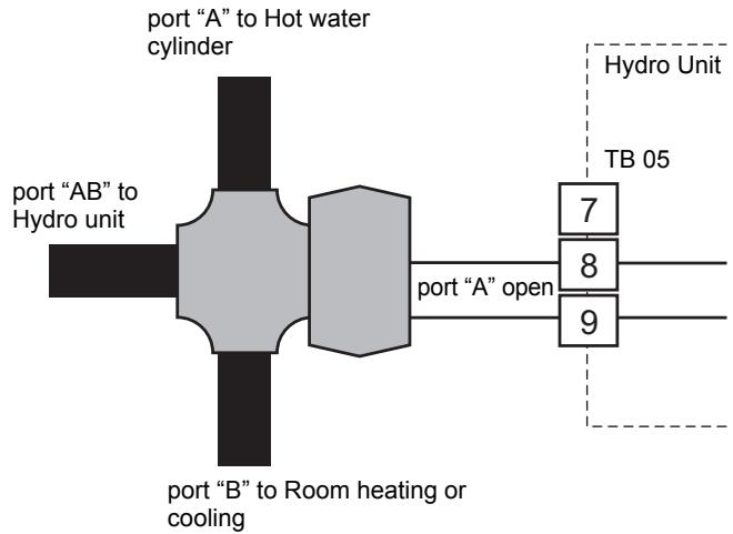
flowchart
graph TD
    A["port "A" to Hot water cylinder"] --> B["port "AB" to Hydro unit"]
    B --> C["port "B" to Room heating or cooling"]
    C --> D["hydro Unit TB 05"]
    D --> E["7"]
    D --> F["8"]
    D --> G["9"]
Type 2: SPST
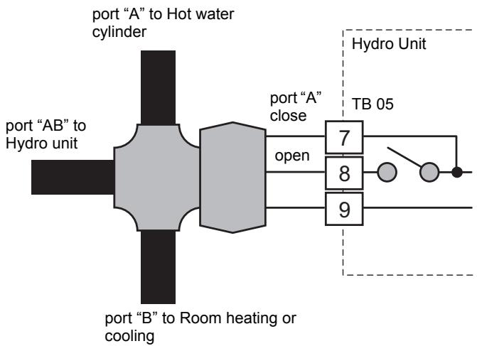
flowchart
graph LR
    A["Port "A" to Hot water cylinder"] --> B["Port "A" close"]
    B --> C["7"]
    B --> D["8"]
    B --> E["9"]
    F["Port "AB" to Hydro unit"] --> G["Port "B" to Room heating or cooling"]
    G --> H["TB 05"]
    H --> I["Open"]
    H --> J["Open"]
    style A fill:#f9f,stroke:#333
    style F fill:#f9f,stroke:#333
    style B fill:#ccf,stroke:#333
    style G fill:#ccf,stroke:#333
    style H fill:#cfc,stroke:#333
    style I fill:#fcc,stroke:#333
Type 3: SPDT
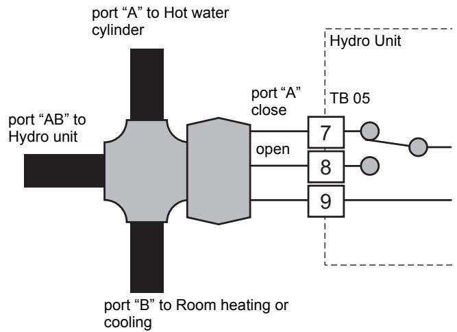
flowchart
graph TD
    A["port "A" to Hot water cylinder"] --> B["port "A" close"]
    B --> C["7 TB 05"]
    B --> D["8"]
    B --> E["9"]
    F["port "AB" to Hydro unit"] --> G[" Port "AB" to Room heating or cooling"]
    G --> H[" Open "]
3-way mixing valve connection
Required Actuator Specification
Electrical Specification: 230 V; 50 Hz; <100 mA
The 3-way mixing valve is used to achieve the temperature differential needed in a 2-zone heating system.
- Connect the 3-way mixing valve to terminals 2, 3 and 4 on Terminal Block 04 (for Type 1 mixing valve) or on terminals 1, 2 and 3 on Terminal Block 04 (for Type 2 mixing valve).
- Connect the 3-way mixing valve in accordance with the diagrams below:-
Type 1: SPDT
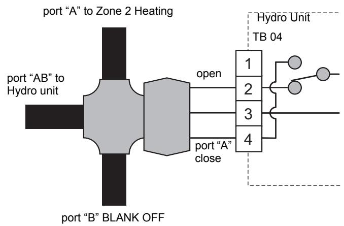
flowchart
graph LR
    A["port "A" to Zone 2 Heating"] --> B["port "AB" to Hydro unit"]
    B --> C["open"]
    C --> D["1"]
    C --> E["2"]
    C --> F["3"]
    C --> G["4"]
    H["port "B" BLANK OFF"] --> I["4"]
    J["Hydro Unit TB 04"] --> K["1"]
    J --> L["2"]
    J --> M["3"]
    J --> N["4"]
Type 2: SPST
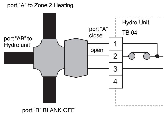
flowchart
graph LR
    A["port "A" to Zone 2 Heating"] --> B["port "AB" to Hydro unit"]
    B --> C["port "A" close"]
    C --> D["1"]
    C --> E["2"]
    C --> F["3"]
    C --> G["4"]
    D --> H["Hydro Unit TB 04"]
    E --> H
    F --> H
    G --> H
    I["port "B" BLANK OFF"] --> C
Hot water cylinder connection (optional)
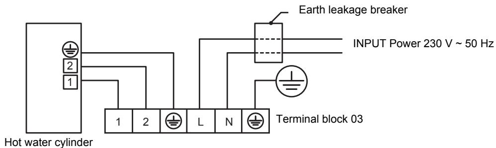
Hot water cylinder electrical box connections
4-5. Capacity Tables
▼Outdoor unit HWS-803H-E Hydro unit HWS-803XWH\*\*-E
Rated heating capacity and power input
| Rated condition 1LWT=35°CdT=5deg | Capacity | kW | 8.0 |
| Power input | kW | 1.82 | |
| COP | W/W | 4.40 | |
| Rated water flow rate | /min | 22.9 | |
| Rated condition 2LWT=45°CdT=5deg | Capacity | kW | 8.0 |
| Power input | kW | 2.40 | |
| COP | W/W | 3.33 | |
| Rated water flow rate | /min | 22.9 |
* Rated heating capacity and power input are the data at rated compressor operating frequency
* Power input does not include water pump power.
* Heating capacity and power input are measured in accordance with EN14511.
TO : Outdoor temperature (DB°C) RH85%
LWT : Leaving water temperature (°C)
dT : Delta temperature (deg)
Leaving water temperature - return water temperature
Average heating capacity and power input
| Capacity (kW) | LWT (°C) | ||||||
| 30 | 35 | 40 | 45 | 50 | 55 | ||
| TO(°C) | -20 | 3.93 | 3.83 | 3.74 | — | — | — |
| -15 | 4.66 | 4.54 | 4.44 | 4.27 | — | — | |
| -7 | 5.45 | 5.30 | 5.15 | 4.99 | 4.84 | — | |
| -2 | 6.24 | 6.11 | 5.97 | 5.84 | 5.69 | 5.55 | |
| 2 | 6.86 | 6.75 | 6.64 | 6.52 | 6.47 | 6.38 | |
| 7 | 9.02 | 8.78 | 8.58 | 8.34 | 8.11 | 7.87 | |
| 10 | 9.56 | 9.29 | 9.10 | 8.84 | 8.42 | 8.29 | |
| 12 | 10.11 | 9.81 | 9.62 | 9.35 | 8.92 | 8.87 | |
| 15 | 10.94 | 10.60 | 10.41 | 10.13 | 9.68 | 9.52 | |
| 20 | 12.42 | 11.99 | 11.82 | 11.50 | 11.03 | 10.78 | |
| Power input (kW) | LWT (°C) | ||||||
| 30 | 35 | 40 | 45 | 50 | 55 | ||
| TO(°C) | -20 | 1.70 | 1.82 | 1.90 | — | — | — |
| -15 | 1.78 | 1.90 | 2.00 | 2.13 | — | — | |
| -7 | 2.06 | 2.21 | 2.33 | 2.47 | 2.79 | — | |
| -2 | 2.10 | 2.26 | 2.39 | 2.56 | 2.86 | 3.14 | |
| 2 | 2.11 | 2.28 | 2.43 | 2.60 | 2.88 | 3.17 | |
| 7 | 1.87 | 2.07 | 2.25 | 2.46 | 2.65 | 2.85 | |
| 10 | 1.84 | 2.03 | 2.21 | 2.42 | 2.61 | 2.86 | |
| 12 | 1.83 | 2.02 | 2.20 | 2.41 | 2.60 | 2.87 | |
| 15 | 1.83 | 2.02 | 2.20 | 2.41 | 2.60 | 2.88 | |
| 20 | 1.82 | 2.01 | 2.18 | 2.44 | 2.58 | 2.91 | |
| COP | LWT (°C) | ||||||
| 30 | 35 | 40 | 45 | 50 | 55 | ||
| TO(°C) | -20 | 2.32 | 2.11 | 1.97 | — | — | — |
| -15 | 2.62 | 2.38 | 2.22 | 2.00 | — | — | |
| -7 | 2.64 | 2.40 | 2.21 | 2.02 | 1.73 | — | |
| -2 | 2.98 | 2.70 | 2.50 | 2.29 | 1.99 | 1.77 | |
| 2 | 3.26 | 2.96 | 2.73 | 2.50 | 2.25 | 2.02 | |
| 7 | 4.82 | 4.25 | 3.82 | 3.39 | 3.06 | 2.76 | |
| 10 | 5.20 | 4.58 | 4.12 | 3.65 | 3.23 | 2.90 | |
| 12 | 5.52 | 4.86 | 4.37 | 3.88 | 3.43 | 3.09 | |
| 15 | 5.98 | 5.25 | 4.73 | 4.20 | 3.72 | 3.31 | |
| 20 | 6.82 | 5.97 | 5.42 | 4.71 | 4.28 | 3.70 | |
* Heating capacity and power input are include defrost cycle data.
* Heating capacity and power input are shown at maximum compressor operating frequency
* Power input does not include water pump power.
* Heating capacity and power input are measured in accordance with EN14511.
TO : Outdoor temperature (DB°C) RH85%
LWT : Leaving water temperature (°C)
Heating peak capacity and power input
| Capacity (kW) | LWT (°C) | ||||||
| 30 | 35 | 40 | 45 | 50 | 55 | ||
| TO(°C) | -20 | 4.11 | 4.01 | 3.92 | — | — | — |
| -15 | 4.87 | 4.74 | 4.62 | 4.46 | — | — | |
| -7 | 6.25 | 6.08 | 5.92 | 5.74 | 5.41 | — | |
| -2 | 7.22 | 7.00 | 6.80 | 6.59 | 6.37 | 5.97 | |
| 2 | 8.17 | 7.91 | 7.67 | 7.43 | 7.17 | 6.92 | |
| 7 | 9.02 | 8.78 | 8.58 | 8.34 | 8.11 | 7.87 | |
| 10 | 9.56 | 9.29 | 9.10 | 8.84 | 8.42 | 8.29 | |
| 12 | 10.11 | 9.81 | 9.62 | 9.35 | 8.92 | 8.87 | |
| 15 | 10.94 | 10.60 | 10.41 | 10.13 | 9.68 | 9.52 | |
| 20 | 12.42 | 11.99 | 11.82 | 11.50 | 11.03 | 10.78 | |
| Power input (kW) | LWT (°C) | ||||||
| 30 | 35 | 40 | 45 | 50 | 55 | ||
| TO(°C) | -20 | 1.72 | 1.85 | 2.04 | — | — | — |
| -15 | 1.83 | 1.97 | 2.17 | 2.30 | — | — | |
| -7 | 1.85 | 2.01 | 2.21 | 2.43 | 2.59 | — | |
| -2 | 1.87 | 2.04 | 2.24 | 2.46 | 2.65 | 2.78 | |
| 2 | 1.86 | 2.04 | 2.24 | 2.45 | 2.65 | 2.80 | |
| 7 | 1.87 | 2.07 | 2.25 | 2.46 | 2.65 | 2.85 | |
| 10 | 1.84 | 2.03 | 2.21 | 2.42 | 2.61 | 2.86 | |
| 12 | 1.83 | 2.02 | 2.20 | 2.41 | 2.60 | 2.87 | |
| 15 | 1.83 | 2.02 | 2.20 | 2.41 | 2.60 | 2.88 | |
| 20 | 1.82 | 2.01 | 2.18 | 2.44 | 2.58 | 2.91 | |
| COP | LWT (°C) | ||||||
| 30 | 35 | 40 | 45 | 50 | 55 | ||
| TO(°C) | -20 | 2.38 | 2.17 | 1.92 | — | — | — |
| -15 | 2.67 | 2.41 | 2.13 | 1.94 | — | — | |
| -7 | 3.37 | 3.02 | 2.68 | 2.37 | 2.09 | — | |
| -2 | 3.85 | 3.43 | 3.04 | 2.68 | 2.40 | 2.15 | |
| 2 | 4.39 | 3.88 | 3.43 | 3.03 | 2.71 | 2.47 | |
| 7 | 4.82 | 4.25 | 3.82 | 3.39 | 3.06 | 2.76 | |
| 10 | 5.20 | 4.58 | 4.12 | 3.65 | 3.23 | 2.90 | |
| 12 | 5.52 | 4.86 | 4.37 | 3.88 | 3.43 | 3.09 | |
| 15 | 5.98 | 5.25 | 4.73 | 4.20 | 3.72 | 3.31 | |
| 20 | 6.82 | 5.97 | 5.42 | 4.71 | 4.28 | 3.70 | |
* Heating capacity and power input are shown peak value during operation.
* Heating capacity and power input are shown at maximum compressor operating frequency
* Power input does not include water pump power.
TO : Outdoor temperature (DB°C) RH85%
LWT : Leaving water temperature (°C)
▼Outdoor unit HWS-803H-E Hydro unit HWS-803XWH\*\*-E
Rated cooling capacity and power input
| Rated condition 1LWT=7°CdT=5deg | Capacity | kW | 6.0 |
| Power input | kW | 2.13 | |
| EER | W/W | 2.82 | |
| Rated water flow rate | /min | 17.2 | |
| Rated condition 2LWT=18°CdT=5deg | Capacity | kW | 6.0 |
| Power input | kW | 1.42 | |
| EER | W/W | 4.23 | |
| Rated water flow rate | /min | 17.2 |
* Rated cooling capacity and power input are the data at rated compressor operating frequency
* Power input does not include water pump power.
* Cooling capacity and power input are measured in accordance with EN14511.
TO : Outdoor temperature (DB°C)
LWT : Leaving water temperature (°C)
dT : Delta temperature (deg)
Return water temperature - leaving water temperature
Cooling capacity and power input
| Capacity (kW) | LWT (°C) | |||||
| 7 | 10 | 13 | 15 | 18 | ||
| TO(°C) | 20 | 7.36 | 8.05 | 8.81 | 9.25 | 10.03 |
| 27 | 6.76 | 7.39 | 8.09 | 8.49 | 9.21 | |
| 30 | 6.46 | 7.06 | 7.73 | 8.12 | 8.80 | |
| 35 | 6.00 | 6.56 | 7.18 | 7.54 | 8.18 | |
| 40 | 5.50 | 6.01 | 6.58 | 6.91 | 7.49 | |
| 43 | 4.62 | 5.00 | 5.44 | 5.69 | 6.09 | |
| Power input (kW) | LWT (°C) | |||||
| 7 | 10 | 13 | 15 | 18 | ||
| TO(°C) | 20 | 1.60 | 1.63 | 1.66 | 1.68 | 1.70 |
| 27 | 1.84 | 1.86 | 1.90 | 1.92 | 1.95 | |
| 30 | 1.90 | 1.93 | 1.97 | 2.00 | 2.02 | |
| 35 | 2.13 | 2.16 | 2.20 | 2.23 | 2.26 | |
| 40 | 2.30 | 2.34 | 2.38 | 2.41 | 2.44 | |
| 43 | 2.09 | 2.09 | 2.09 | 2.09 | 2.09 | |
| COP | LWT (°C) | |||||
| 7 | 10 | 13 | 15 | 18 | ||
| TO(°C) | 20 | 4.60 | 4.95 | 5.32 | 5.51 | 5.91 |
| 27 | 3.68 | 3.97 | 4.26 | 4.41 | 4.73 | |
| 30 | 3.39 | 3.65 | 3.92 | 4.07 | 4.36 | |
| 35 | 2.82 | 3.04 | 3.26 | 3.38 | 3.62 | |
| 40 | 2.39 | 2.57 | 2.76 | 2.86 | 3.07 | |
| 43 | 2.21 | 2.40 | 2.60 | 2.72 | 2.91 | |
* Cooling capacity and power input are the data at rated compressor operating frequency of rated condition 1
* Power input does not include water pump power.
* Cooling capacity and power input are measured in accordance with EN14511.
TO : Outdoor temperature (DB°C)
LWT : Leaving water temperature (°C)
Heating capacity and input specifications
▼Outdoor unit HWS-1103H-E Hydro unit HWS-1403XWH\*\*-E
Rated heating capacity and power input
| Rated condition 1LWT=35°CdT=5deg | Capacity | kW | 11.2 |
| Power input | kW | 2.35 | |
| COP | W/W | 4.77 | |
| Rated water flow rate | /min | 32.1 | |
| Rated condition 2LWT=45°CdT=5deg | Capacity | kW | 11.2 |
| Power input | kW | 2.95 | |
| COP | W/W | 3.80 | |
| Rated water flow rate | /min | 32.1 |
* Rated heating capacity and power input are the data at rated compressor operating frequency
* Power input does not include water pump power.
* Heating capacity and power input are measured in accordance with EN14511.
TO : Outdoor temperature (DB°C) RH85%
LWT : Leaving water temperature (°C)
dT : Delta temperature (deg)
Leaving water temperature - return water temperature
Average heating capacity and power input
| Capacity (kW) | LWT (°C) | ||||||
| 30 | 35 | 40 | 45 | 50 | 55 | ||
| TO(°C) | -20 | 5.66 | 5.48 | 5.34 | 5.23 | — | — |
| -15 | 7.09 | 6.86 | 6.69 | 6.55 | — | — | |
| -7 | 8.68 | 8.40 | 8.19 | 8.02 | 7.69 | — | |
| -2 | 10.23 | 9.90 | 9.65 | 9.46 | 9.07 | 7.97 | |
| 2 | 10.90 | 10.55 | 10.28 | 10.08 | 9.66 | 8.49 | |
| 7 | 15.47 | 14.97 | 14.59 | 14.30 | 13.71 | 11.48 | |
| 10 | 16.40 | 15.87 | 15.47 | 15.16 | 14.53 | 12.17 | |
| 12 | 17.35 | 16.62 | 16.20 | 15.88 | 15.22 | 12.75 | |
| 15 | 18.84 | 17.70 | 17.25 | 16.91 | 16.21 | 13.57 | |
| 20 | 21.71 | 20.01 | 19.50 | 19.11 | 18.33 | 15.35 | |
| Power input (kW) | LWT (°C) | ||||||
| 30 | 35 | 40 | 45 | 50 | 55 | ||
| TO(°C) | -20 | 2.76 | 2.97 | 3.26 | 3.57 | — | — |
| -15 | 2.87 | 3.09 | 3.40 | 3.71 | — | — | |
| -7 | 3.16 | 3.40 | 3.74 | 4.08 | 4.43 | — | |
| -2 | 3.11 | 3.35 | 3.68 | 4.02 | 4.37 | 4.32 | |
| 2 | 3.07 | 3.30 | 3.63 | 3.96 | 4.30 | 4.26 | |
| 7 | 3.00 | 3.23 | 3.55 | 3.88 | 4.21 | 4.17 | |
| 10 | 2.98 | 3.21 | 3.53 | 3.86 | 4.18 | 4.14 | |
| 12 | 2.97 | 3.20 | 3.52 | 3.84 | 4.17 | 4.13 | |
| 15 | 2.96 | 3.19 | 3.51 | 3.83 | 4.16 | 4.12 | |
| 20 | 2.94 | 3.17 | 3.48 | 3.81 | 4.13 | 4.09 | |
| COP | LWT (°C) | ||||||
| 30 | 35 | 40 | 45 | 50 | 55 | ||
| TO(°C) | -20 | 2.05 | 1.85 | 1.64 | 1.46 | — | — |
| -15 | 2.47 | 2.22 | 1.97 | 1.77 | — | — | |
| -7 | 2.75 | 2.47 | 2.19 | 1.96 | 1.74 | — | |
| -2 | 3.29 | 2.96 | 2.62 | 2.35 | 2.08 | 1.84 | |
| 2 | 3.56 | 3.20 | 2.83 | 2.54 | 2.25 | 1.99 | |
| 7 | 5.16 | 4.63 | 4.11 | 3.69 | 3.26 | 2.75 | |
| 10 | 5.50 | 4.94 | 4.38 | 3.93 | 3.48 | 2.94 | |
| 12 | 5.84 | 5.19 | 4.60 | 4.14 | 3.65 | 3.09 | |
| 15 | 6.36 | 5.55 | 4.91 | 4.42 | 3.90 | 3.29 | |
| 20 | 7.38 | 6.31 | 5.60 | 5.02 | 4.44 | 3.75 | |
* Heating capacity and power input are include defrost cycle data.
* Heating capacity and power input are shown at maximum compressor operating frequency
* Power input does not include water pump power.
* Heating capacity and power input are measured in accordance with EN14511.
TO : Outdoor temperature (DB°C) RH85%
LWT : Leaving water temperature (°C)
Heating peak capacity and power input
| Capacity (kW) | LWT (°C) | ||||||
| 30 | 35 | 40 | 45 | 50 | 55 | ||
| TO(°C) | -20 | 6.64 | 6.48 | 6.37 | 6.18 | — | — |
| -15 | 8.07 | 7.86 | 7.71 | 7.53 | — | — | |
| -7 | 10.40 | 10.10 | 9.89 | 9.69 | 9.23 | — | |
| -2 | 12.04 | 11.68 | 11.41 | 11.18 | 10.73 | 8.99 | |
| 2 | 13.41 | 12.98 | 12.65 | 12.40 | 11.90 | 9.97 | |
| 7 | 15.47 | 14.97 | 14.59 | 14.30 | 13.71 | 11.48 | |
| 10 | 16.40 | 15.87 | 15.47 | 15.16 | 14.53 | 12.17 | |
| 12 | 17.35 | 16.62 | 16.20 | 15.88 | 15.22 | 12.75 | |
| 15 | 18.84 | 17.70 | 17.25 | 16.91 | 16.21 | 13.57 | |
| 20 | 21.71 | 20.01 | 19.50 | 19.11 | 18.33 | 15.35 | |
| Power input (kW) | LWT (°C) | ||||||
| 30 | 35 | 40 | 45 | 50 | 55 | ||
| TO(°C) | -20 | 2.63 | 2.78 | 3.08 | 3.36 | — | — |
| -15 | 2.81 | 2.99 | 3.30 | 3.60 | — | — | |
| -7 | 2.91 | 3.11 | 3.43 | 3.75 | 4.07 | — | |
| -2 | 2.96 | 3.17 | 3.49 | 3.82 | 4.15 | 4.10 | |
| 2 | 2.96 | 3.19 | 3.51 | 3.84 | 4.17 | 4.13 | |
| 7 | 3.00 | 3.23 | 3.55 | 3.88 | 4.21 | 4.17 | |
| 10 | 2.98 | 3.21 | 3.53 | 3.86 | 4.18 | 4.14 | |
| 12 | 2.97 | 3.20 | 3.52 | 3.84 | 4.17 | 4.13 | |
| 15 | 2.96 | 3.19 | 3.51 | 3.83 | 4.16 | 4.12 | |
| 20 | 2.94 | 3.17 | 3.48 | 3.81 | 4.13 | 4.09 | |
| COP | LWT (°C) | ||||||
| 30 | 35 | 40 | 45 | 50 | 55 | ||
| TO(°C) | -20 | 2.53 | 2.33 | 2.07 | 1.84 | — | — |
| -15 | 2.87 | 2.63 | 2.33 | 2.09 | — | — | |
| -7 | 3.57 | 3.25 | 2.89 | 2.58 | 2.27 | — | |
| -2 | 4.07 | 3.68 | 3.27 | 2.93 | 2.59 | 2.19 | |
| 2 | 4.53 | 4.07 | 3.61 | 3.23 | 2.86 | 2.41 | |
| 7 | 5.16 | 4.63 | 4.11 | 3.69 | 3.26 | 2.75 | |
| 10 | 5.50 | 4.94 | 4.38 | 3.93 | 3.48 | 2.94 | |
| 12 | 5.84 | 5.19 | 4.60 | 4.14 | 3.65 | 3.09 | |
| 15 | 6.36 | 5.55 | 4.91 | 4.42 | 3.90 | 3.29 | |
| 20 | 7.38 | 6.31 | 5.60 | 5.02 | 4.44 | 3.75 | |
* Heating capacity and power input are shown peak value during operation
* Heating capacity and power input are shown at maximum compressor operating frequency
* Power input does not include water pump power.
TO : Outdoor temperature (DB°C) RH85%
LWT : Leaving water temperature (°C)
Cooling capacity and input specifications
▼Outdoor unit HWS-1103H-E Hydro unit HWS-1403XWH\*\*-E
Rated cooling capacity and power input
| Rated condition 1LWT=7°CdT=5deg | Capacity | kW | 10.0 |
| Power input | kW | 3.52 | |
| EER | W/W | 2.84 | |
| Rated water flow rate | /min | 28.7 | |
| Rated condition 2LWT=18°CdT=5deg | Capacity | kW | 10 |
| Power input | kW | 2.35 | |
| EER | W/W | 4.26 | |
| Rated water flow rate | /min | 28.7 |
* Rated cooling capacity and power input are the data at rated compressor operating frequency
* Power input does not include water pump power.
* Cooling capacity and power input are measured in accordance with EN14511.
TO : Outdoor temperature (DB°C)
LWT : Leaving water temperature (°C)
dT : Delta temperature (deg)
Return water temperature - leaving water temperature
Cooling capacity and power input
| Capacity (kW) | LWT (°C) | |||||
| 7 | 10 | 13 | 15 | 18 | ||
| TO (°C) | 20 | 12.78 | 13.64 | 14.99 | 16.03 | 16.98 |
| 27 | 11.60 | 12.38 | 13.61 | 14.55 | 15.42 | |
| 30 | 11.03 | 11.77 | 12.94 | 13.83 | 14.66 | |
| 35 | 10.00 | 10.67 | 11.73 | 12.54 | 13.29 | |
| 40 | 8.96 | 9.56 | 10.51 | 11.24 | 11.91 | |
| 43 | 6.89 | 7.35 | 8.08 | 8.64 | 9.16 | |
| Power input (kW) | LWT (°C) | |||||
| 7 | 10 | 13 | 15 | 18 | ||
| TO(°C) | 20 | 2.64 | 2.70 | 2.74 | 2.77 | 2.78 |
| 27 | 3.04 | 3.11 | 3.16 | 3.18 | 3.20 | |
| 30 | 3.23 | 3.30 | 3.35 | 3.38 | 3.40 | |
| 35 | 3.52 | 3.59 | 3.65 | 3.68 | 3.70 | |
| 40 | 3.82 | 3.84 | 3.86 | 3.88 | 3.91 | |
| 43 | 3.28 | 3.28 | 3.28 | 3.29 | 3.29 | |
| COP | LWT (°C) | |||||
| 7 | 10 | 13 | 15 | 18 | ||
| TO(°C) | 20 | 4.83 | 5.05 | 5.47 | 5.80 | 6.11 |
| 27 | 3.81 | 3.98 | 4.31 | 4.57 | 4.81 | |
| 30 | 3.41 | 3.57 | 3.86 | 4.09 | 4.31 | |
| 35 | 2.84 | 2.97 | 3.21 | 3.41 | 3.59 | |
| 40 | 2.34 | 2.49 | 2.72 | 2.90 | 3.04 | |
| 43 | 2.10 | 2.24 | 2.46 | 2.62 | 2.78 | |
* Cooling capacity and power input are the data at rated compressor operating frequency of rated condition 1
* Power input does not include water pump power.
* Cooling capacity and power input are measured in accordance with EN14511.
TO : Outdoor temperature (DB°C)
LWT : Leaving water temperature (°C)
Heating capacity and input specifications
▼Outdoor unit HWS-1403H-E Hydro unit HWS-1403XWH\*\*-E
Rated heating capacity and power input
| Rated condition 1LWT=35°CdT=5deg | Capacity | kW | 14.0 |
| Power input | kW | 3.11 | |
| COP | W/W | 4.50 | |
| Rated water flow rate | /min | 40.1 | |
| Rated condition 2LWT=45°CdT=5deg | Capacity | kW | 14.0 |
| Power input | kW | 3.95 | |
| COP | W/W | 3.54 | |
| Rated water flow rate | /min | 40.1 |
* Rated heating capacity and power input are the data at rated compressor operating frequency
* Power input does not include water pump power.
* Heating capacity and power input are measured in accordance with EN14511.
TO : Outdoor temperature (DB°C) RH85%
LWT : Leaving water temperature (°C)
dT : Delta temperature (deg)
Leaving water temperature - return water temperature
Average heating capacity and power input
| Capacity (kW) | LWT (°C) | ||||||
| 30 | 35 | 40 | 45 | 50 | 55 | ||
| TO(°C) | -20 | 6.43 | 6.18 | 5.94 | 5.43 | — | — |
| -15 | 8.26 | 7.94 | 7.64 | 6.98 | — | — | |
| -7 | 9.75 | 9.37 | 9.01 | 8.24 | 7.42 | — | |
| -2 | 11.37 | 10.93 | 10.52 | 9.61 | 8.66 | 8.15 | |
| 2 | 12.03 | 11.56 | 11.12 | 10.17 | 9.16 | 8.62 | |
| 7 | 17.77 | 17.08 | 16.43 | 15.02 | 13.53 | 12.13 | |
| 10 | 18.66 | 17.93 | 17.25 | 15.77 | 14.21 | 12.74 | |
| 12 | 19.92 | 18.96 | 18.24 | 16.67 | 15.02 | 13.47 | |
| 15 | 21.53 | 20.09 | 19.33 | 17.67 | 15.91 | 14.27 | |
| 20 | 23.89 | 21.87 | 21.04 | 19.23 | 17.32 | 15.53 | |
| Power input (kW) | LWT (°C) | ||||||
| 30 | 35 | 40 | 45 | 50 | 55 | ||
| TO(°C) | -20 | 3.24 | 3.50 | 3.76 | 3.77 | — | — |
| -15 | 3.41 | 3.69 | 3.96 | 3.98 | — | — | |
| -7 | 3.80 | 4.10 | 4.40 | 4.42 | 4.44 | — | |
| -2 | 3.74 | 4.04 | 4.34 | 4.36 | 4.38 | 4.41 | |
| 2 | 3.69 | 3.98 | 4.27 | 4.29 | 4.31 | 4.34 | |
| 7 | 3.65 | 3.94 | 4.23 | 4.25 | 4.27 | 4.30 | |
| 10 | 3.65 | 3.94 | 4.23 | 4.25 | 4.27 | 4.30 | |
| 12 | 3.66 | 3.95 | 4.24 | 4.26 | 4.28 | 4.31 | |
| 15 | 3.69 | 3.98 | 4.28 | 4.30 | 4.32 | 4.35 | |
| 20 | 3.48 | 3.75 | 4.03 | 4.05 | 4.07 | 4.10 | |
| COP | LWT (°C) | ||||||
| 30 | 35 | 40 | 45 | 50 | 55 | ||
| TO(°C) | -20 | 1.98 | 1.77 | 1.58 | 1.44 | — | — |
| -15 | 2.42 | 2.15 | 1.93 | 1.75 | — | — | |
| -7 | 2.57 | 2.29 | 2.05 | 1.86 | 1.67 | — | |
| -2 | 3.04 | 2.71 | 2.43 | 2.21 | 1.98 | 1.85 | |
| 2 | 3.26 | 2.91 | 2.60 | 2.37 | 2.12 | 1.99 | |
| 7 | 4.87 | 4.34 | 3.88 | 3.53 | 3.17 | 2.82 | |
| 10 | 5.11 | 4.55 | 4.08 | 3.71 | 3.33 | 2.96 | |
| 12 | 5.44 | 4.80 | 4.30 | 3.91 | 3.51 | 3.13 | |
| 15 | 5.83 | 5.05 | 4.52 | 4.11 | 3.68 | 3.28 | |
| 20 | 6.86 | 5.83 | 5.22 | 4.75 | 4.26 | 3.79 | |
* Heating capacity and power input are include defrost cycle data.
* Heating capacity and power input are shown at maximum operating frequency
* Power input does not include water pump power.
* Heating capacity and power input are measured in accordance with EN14511.
TO : Outdoor temperature (DB°C) RH85%
LWT : Leaving water temperature (°C)
Heating peak capacity and power input
| Capacity (kW) | LWT (°C) | ||||||
| 30 | 35 | 40 | 45 | 50 | 55 | ||
| TO(°C) | -20 | 7.12 | 6.90 | 6.69 | 6.08 | — | — |
| -15 | 9.36 | 9.05 | 8.76 | 7.95 | — | — | |
| -7 | 12.15 | 11.72 | 11.32 | 10.35 | 9.28 | — | |
| -2 | 14.09 | 13.57 | 13.08 | 11.96 | 10.78 | 9.23 | |
| 2 | 15.35 | 14.75 | 14.19 | 12.97 | 11.70 | 10.01 | |
| 7 | 17.77 | 17.08 | 16.43 | 15.02 | 13.53 | 12.13 | |
| 10 | 18.66 | 17.93 | 17.25 | 15.77 | 14.21 | 12.74 | |
| 12 | 19.92 | 18.96 | 18.24 | 16.67 | 15.02 | 13.47 | |
| 15 | 21.53 | 20.09 | 19.33 | 17.67 | 15.91 | 14.27 | |
| 20 | 23.89 | 21.87 | 21.04 | 19.23 | 17.32 | 15.53 | |
| Power input (kW) | LWT (°C) | ||||||
| 30 | 35 | 40 | 45 | 50 | 55 | ||
| TO(°C) | -20 | 3.12 | 3.30 | 3.57 | 3.58 | — | — |
| -15 | 3.31 | 3.52 | 3.80 | 3.82 | — | — | |
| -7 | 3.52 | 3.77 | 4.06 | 4.08 | 4.10 | — | |
| -2 | 3.60 | 3.87 | 4.16 | 4.19 | 4.21 | 4.24 | |
| 2 | 3.59 | 3.88 | 4.16 | 4.18 | 4.21 | 4.25 | |
| 7 | 3.65 | 3.94 | 4.23 | 4.25 | 4.27 | 4.30 | |
| 10 | 3.65 | 3.94 | 4.23 | 4.25 | 4.27 | 4.30 | |
| 12 | 3.66 | 3.95 | 4.24 | 4.26 | 4.28 | 4.31 | |
| 15 | 3.69 | 3.98 | 4.28 | 4.30 | 4.32 | 4.35 | |
| 20 | 3.48 | 3.75 | 4.03 | 4.05 | 4.07 | 4.10 | |
| COP | LWT (°C) | ||||||
| 30 | 35 | 40 | 45 | 50 | 55 | ||
| TO(°C) | -20 | 2.28 | 2.09 | 1.87 | 1.70 | — | — |
| -15 | 2.83 | 2.57 | 2.30 | 2.08 | — | — | |
| -7 | 3.45 | 3.11 | 2.79 | 2.54 | 2.26 | — | |
| -2 | 3.91 | 3.51 | 3.14 | 2.86 | 2.56 | 2.18 | |
| 2 | 4.27 | 3.81 | 3.41 | 3.10 | 2.78 | 2.36 | |
| 7 | 4.87 | 4.34 | 3.88 | 3.53 | 3.17 | 2.82 | |
| 10 | 5.11 | 4.55 | 4.08 | 3.71 | 3.33 | 2.96 | |
| 12 | 5.44 | 4.80 | 4.30 | 3.91 | 3.51 | 3.13 | |
| 15 | 5.83 | 5.05 | 4.52 | 4.11 | 3.68 | 3.28 | |
| 20 | 6.86 | 5.83 | 5.22 | 4.75 | 4.26 | 3.79 | |
* Heating capacity and power input are shown peak value during operation
* Heating capacity and power input are shown at maximum compressor operating frequency
* Power input does not include water pump power.
TO : Outdoor temperature (DB°C) RH85%
LWT : Leaving water temperature (°C)
Cooling capacity and input specifications
▼Outdoor unit HWS-1403H-E Hydro unit HWS-1403XWH\*\*-E
Rated cooling capacity and power input
| Rated condition 1LWT=7°CdT=5deg | Capacity | kW | 11.0 |
| Power input | kW | 4.08 | |
| EER | W/W | 2.70 | |
| Rated water flow rate | /min | 31.5 | |
| Rated condition 2LWT=18°CdT=5deg | Capacity | kW | 11.0 |
| Power input | kW | 2.65 | |
| EER | W/W | 4.15 | |
| Rated water flow rate | /min | 31.5 |
* Rated cooling capacity and power input are the data at rated compressor operating frequency
* Power input does not include water pump power.
* Cooling capacity and power input are measured in accordance with EN14511.
TO : Outdoor temperature (DB°C)
LWT : Leaving water temperature (°C)
dT : Delta temperature (deg)
Return water temperature - Leaving water temperature
Cooling capacity and power input
| Capacity (kW) | LWT (°C) | |||||
| 7 | 10 | 13 | 15 | 18 | ||
| TO (°C) | 20 | 13.95 | 15.48 | 16.82 | 17.53 | 18.34 |
| 27 | 12.60 | 13.98 | 15.19 | 15.83 | 16.56 | |
| 30 | 12.01 | 13.33 | 14.49 | 15.10 | 15.80 | |
| 35 | 11.00 | 12.21 | 13.27 | 13.83 | 14.47 | |
| 40 | 8.83 | 9.80 | 10.65 | 11.10 | 11.62 | |
| 43 | 6.81 | 7.56 | 8.21 | 8.56 | 8.95 | |
| Power input (kW) | LWT (°C) | |||||
| 7 | 10 | 13 | 15 | 18 | ||
| TO(°C) | 20 | 3.14 | 3.21 | 3.26 | 3.27 | 3.30 |
| 27 | 3.57 | 3.64 | 3.70 | 3.72 | 3.76 | |
| 30 | 3.77 | 3.85 | 3.91 | 3.92 | 3.97 | |
| 35 | 4.08 | 4.17 | 4.23 | 4.25 | 4.29 | |
| 40 | 3.84 | 3.85 | 3.85 | 3.87 | 3.88 | |
| 43 | 3.25 | 3.23 | 3.23 | 3.22 | 3.22 | |
| EER | LWT (°C) | |||||
| 7 | 10 | 13 | 15 | 18 | ||
| TO(°C) | 20 | 4.44 | 4.83 | 5.16 | 5.36 | 5.55 |
| 27 | 3.53 | 3.84 | 4.10 | 4.26 | 4.41 | |
| 30 | 3.19 | 3.46 | 3.71 | 3.85 | 3.98 | |
| 35 | 2.70 | 2.93 | 3.14 | 3.26 | 3.37 | |
| 40 | 2.30 | 2.55 | 2.76 | 2.87 | 3.00 | |
| 43 | 2.10 | 2.34 | 2.54 | 2.65 | 2.78 | |
* Cooling capacity and power input are the data at rated compressor operating frequency of rated condition 1
* Power input does not include water pump power.
* Cooling capacity and power input are measured in accordance with EN14511.
TO : Outdoor temperature (DB°C)
LWT : Leaving water temperature (°C)
Heating capacity and input specifications
▼Outdoor unit HWS-1103H8-E, HWS-1103H8R-E Hydro unit HWS-1403XWH\*\*-E
Rated heating capacity and power input
| Rated condition 1LWT=35°CdT=5deg | Capacity | kW | 11.2 |
| Power input | kW | 2.39 | |
| COP | W/W | 4.69 | |
| Rated water flow rate | /min | 32.1 | |
| Rated condition 2LWT=45°CdT=5deg | Capacity | kW | 11.2 |
| Power input | kW | 3.19 | |
| COP | W/W | 3.51 | |
| Rated water flow rate | /min | 32.1 |
* Rated heating capacity and power input are the data at rated compressor operating frequency
* Power input does not include water pump power.
* Heating capacity and power input are measured in accordance with EN14511.
TO : Outdoor temperature (DB°C) RH85%
LWT : Leaving water temperature (°C)
dT : Delta temperature (deg)
Leaving water temperature - return water temperature
Average heating capacity and power input
| Capacity (kW) | LWT (°C) | ||||||
| 30 | 35 | 40 | 45 | 50 | 55 | ||
| TO(°C) | -20 | 5.65 | 5.45 | 5.31 | 5.18 | — | — |
| -15 | 7.39 | 7.12 | 6.93 | 6.76 | — | — | |
| -7 | 8.76 | 8.43 | 8.19 | 7.99 | 7.86 | — | |
| -2 | 9.97 | 9.57 | 9.28 | 9.03 | 8.87 | 8.29 | |
| 2 | 11.18 | 10.49 | 10.16 | 9.87 | 9.68 | 9.04 | |
| 7 | 15.41 | 14.82 | 14.47 | 14.16 | 13.81 | 12.82 | |
| 10 | 16.46 | 15.82 | 15.42 | 15.08 | 14.96 | 14.14 | |
| 12 | 17.15 | 16.49 | 16.06 | 15.69 | 15.58 | 14.87 | |
| 15 | 18.11 | 17.41 | 17.19 | 17.02 | 16.62 | 15.76 | |
| 20 | 20.27 | 19.49 | 19.25 | 19.07 | 18.81 | 17.67 | |
| Power input (kW) | LWT (°C) | ||||||
| 30 | 35 | 40 | 45 | 50 | 55 | ||
| TO(°C) | -20 | 2.59 | 2.78 | 2.94 | 3.08 | — | — |
| -15 | 2.89 | 3.11 | 3.29 | 3.46 | — | — | |
| -7 | 3.23 | 3.47 | 3.69 | 3.89 | 4.15 | — | |
| -2 | 3.18 | 3.42 | 3.64 | 3.85 | 4.11 | 4.32 | |
| 2 | 3.15 | 3.38 | 3.61 | 3.81 | 4.07 | 4.28 | |
| 7 | 3.01 | 3.24 | 3.56 | 3.88 | 4.22 | 4.52 | |
| 10 | 3.01 | 3.23 | 3.57 | 3.91 | 4.27 | 4.59 | |
| 12 | 3.00 | 3.23 | 3.57 | 3.92 | 4.30 | 4.64 | |
| 15 | 3.01 | 3.24 | 3.60 | 3.97 | 4.36 | 4.72 | |
| 20 | 3.04 | 3.27 | 3.64 | 4.02 | 4.43 | 4.80 | |
| COP | LWT (°C) | ||||||
| 30 | 35 | 40 | 45 | 50 | 55 | ||
| TO(°C) | -20 | 2.18 | 1.96 | 1.81 | 1.68 | — | — |
| -15 | 2.56 | 2.29 | 2.10 | 1.95 | — | — | |
| -7 | 2.71 | 2.43 | 2.22 | 2.05 | 1.89 | — | |
| -2 | 3.13 | 2.80 | 2.55 | 2.35 | 2.16 | 1.92 | |
| 2 | 3.55 | 3.10 | 2.82 | 2.59 | 2.38 | 2.11 | |
| 7 | 5.12 | 4.57 | 4.06 | 3.65 | 3.27 | 2.84 | |
| 10 | 5.47 | 4.89 | 4.32 | 3.86 | 3.51 | 3.08 | |
| 12 | 5.71 | 5.11 | 4.49 | 4.00 | 3.62 | 3.21 | |
| 15 | 6.01 | 5.37 | 4.77 | 4.29 | 3.81 | 3.34 | |
| 20 | 6.67 | 5.96 | 5.29 | 4.75 | 4.25 | 3.68 | |
* Heating capacity and power input are include defrost cycle data.
* Heating capacity and power input are shown at maximum compressor operating frequency
* Power input does not include water pump power.
* Heating capacity and power input are measured in accordance with EN14511.
TO : Outdoor temperature (DB°C) RH85%
LWT : Leaving water temperature (°C)
Heating peak capacity and power input
| Capacity (kW) | LWT (°C) | ||||||
| 30 | 35 | 40 | 45 | 50 | 55 | ||
| TO(°C) | -20 | 6.69 | 6.41 | 6.21 | 6.03 | — | — |
| -15 | 7.97 | 7.64 | 7.40 | 7.19 | — | — | |
| -7 | 10.38 | 9.96 | 9.65 | 9.38 | 9.10 | — | |
| -2 | 11.85 | 11.38 | 11.05 | 10.75 | 10.43 | 9.64 | |
| 2 | 13.02 | 12.52 | 12.16 | 11.85 | 11.49 | 10.62 | |
| 7 | 15.41 | 14.82 | 14.47 | 14.16 | 13.81 | 12.82 | |
| 10 | 16.46 | 15.82 | 15.42 | 15.08 | 14.96 | 14.14 | |
| 12 | 17.15 | 16.49 | 16.06 | 15.69 | 15.58 | 14.87 | |
| 15 | 18.11 | 17.41 | 17.19 | 17.02 | 16.62 | 15.76 | |
| 20 | 20.27 | 19.49 | 19.25 | 19.07 | 18.81 | 17.67 | |
| Power input (kW) | LWT (°C) | ||||||
| 30 | 35 | 40 | 45 | 50 | 55 | ||
| TO(°C) | -20 | 2.31 | 2.48 | 2.68 | 2.88 | — | — |
| -15 | 2.66 | 2.86 | 3.10 | 3.33 | — | — | |
| -7 | 2.85 | 3.07 | 3.33 | 3.57 | 3.86 | — | |
| -2 | 2.91 | 3.14 | 3.41 | 3.67 | 3.96 | 4.20 | |
| 2 | 2.96 | 3.19 | 3.47 | 3.74 | 4.04 | 4.29 | |
| 7 | 3.01 | 3.24 | 3.56 | 3.88 | 4.22 | 4.52 | |
| 10 | 3.01 | 3.23 | 3.57 | 3.91 | 4.27 | 4.59 | |
| 12 | 3.00 | 3.23 | 3.57 | 3.92 | 4.30 | 4.64 | |
| 15 | 3.01 | 3.24 | 3.60 | 3.97 | 4.36 | 4.72 | |
| 20 | 3.04 | 3.27 | 3.64 | 4.02 | 4.43 | 4.80 | |
| COP | LWT (°C) | ||||||
| 30 | 35 | 40 | 45 | 50 | 55 | ||
| TO(°C) | -20 | 2.90 | 2.59 | 2.31 | 2.09 | — | — |
| -15 | 2.99 | 2.67 | 2.38 | 2.16 | — | — | |
| -7 | 3.64 | 3.24 | 2.90 | 2.62 | 2.36 | — | |
| -2 | 4.07 | 3.63 | 3.24 | 2.93 | 2.64 | 2.29 | |
| 2 | 4.41 | 3.92 | 3.51 | 3.17 | 2.85 | 2.48 | |
| 7 | 5.12 | 4.57 | 4.06 | 3.65 | 3.27 | 2.84 | |
| 10 | 5.47 | 4.89 | 4.32 | 3.86 | 3.51 | 3.08 | |
| 12 | 5.71 | 5.11 | 4.49 | 4.00 | 3.62 | 3.21 | |
| 15 | 6.01 | 5.37 | 4.77 | 4.29 | 3.81 | 3.34 | |
| 20 | 6.67 | 5.96 | 5.29 | 4.75 | 4.25 | 3.68 | |
* Heating capacity and power input are shown peak value during operation.
* Heating capacity and power input are shown at maximum compressor operating frequency
* Power input does not include water pump power.
TO : Outdoor temperature (DB°C) RH85%
LWT : Leaving water temperature (°C)
Cooling capacity and input specifications
▼Outdoor unit HWS-1103H8-E, HWS-1103H8R-E Hydro unit HWS-1403XWH\*\*-E
Rated cooling capacity and power input
| Rated condition 1LWT=7°CdT=5deg | Capacity | kW | 10.0 |
| Power input | kW | 3.52 | |
| EER | W/W | 2.84 | |
| Rated water flow rate | /min | 28.7 | |
| Rated condition 2LWT=18°CdT=5deg | Capacity | kW | 10.0 |
| Power input | kW | 2.14 | |
| EER | W/W | 4.67 | |
| Rated water flow rate | /min | 28.7 |
* Rated cooling capacity and power input are the data at rated compressor operating frequency
* Power input does not include water pump power.
* Cooling capacity and power input are measured in accordance with EN14511.
TO : Outdoor temperature (DB°C)
LWT : Leaving water temperature (°C)
dT : Delta temperature (deg)
Return water temperature - leaving water temperature
Cooling capacity and power input
| Capacity (kW) | LWT (°C) | |||||
| 7 | 10 | 13 | 15 | 18 | ||
| TO (°C) | 20 | 10.09 | 11.06 | 12.03 | 12.67 | 13.63 |
| 27 | 10.40 | 11.40 | 12.40 | 13.06 | 14.05 | |
| 30 | 10.02 | 10.98 | 11.95 | 12.58 | 13.54 | |
| 35 | 9.37 | 10.27 | 11.17 | 11.77 | 12.66 | |
| 40 | 8.66 | 9.50 | 10.33 | 10.88 | 11.57 | |
| 43 | 8.24 | 9.03 | 9.82 | 10.35 | 10.91 | |
| Power input (kW) | LWT (°C) | |||||
| 7 | 10 | 13 | 15 | 18 | ||
| TO(°C) | 20 | 2.04 | 2.07 | 2.10 | 2.12 | 2.14 |
| 27 | 2.67 | 2.71 | 2.75 | 2.77 | 2.80 | |
| 30 | 2.80 | 2.84 | 2.88 | 2.91 | 2.94 | |
| 35 | 3.00 | 3.05 | 3.10 | 3.12 | 3.15 | |
| 40 | 3.32 | 3.37 | 3.42 | 3.45 | 3.47 | |
| 43 | 3.51 | 3.56 | 3.62 | 3.64 | 3.66 | |
| COP | LWT (°C) | |||||
| 7 | 10 | 13 | 15 | 18 | ||
| TO(°C) | 20 | 4.94 | 5.34 | 5.72 | 5.98 | 6.37 |
| 27 | 3.89 | 4.20 | 4.50 | 4.71 | 5.02 | |
| 30 | 3.58 | 3.86 | 4.14 | 4.33 | 4.61 | |
| 35 | 3.12 | 3.37 | 3.61 | 3.77 | 4.02 | |
| 40 | 2.61 | 2.82 | 3.02 | 3.16 | 3.34 | |
| 43 | 2.35 | 2.53 | 2.72 | 2.84 | 2.98 | |
* Cooling capacity and power input are the data at rated compressor operating frequency of rated condition 1
* Power input does not include water pump power.
* Cooling capacity and power input are measured in accordance with EN14511.
TO : Outdoor temperature (DB°C)
LWT : Leaving water temperature (°C)
Heating capacity and input specifications
▼Outdoor unit HWS-1403H8-E, HWS-1403H8R-E Hydro unit HWS-1403XWH\*\*-E
Rated heating capacity and power input
| Rated condition 1LWT=35°CdT=5deg | Capacity | kW | 14.0 |
| Power input | kW | 3.21 | |
| COP | W/W | 4.36 | |
| Rated water flow rate | /min | 40.1 | |
| Rated condition 2LWT=45°CdT=5deg | Capacity | kW | 14.0 |
| Power input | kW | 4.12 | |
| COP | W/W | 3.40 | |
| Rated water flow rate | /min | 40.1 |
* Rated heating capacity and power input are the data at rated compressor operating frequency
* Power input does not include water pump power.
* Heating capacity and power input are measured in accordance with EN14511.
TO : Outdoor temperature (DB°C) RH85%
LWT : Leaving water temperature (°C)
dT : Delta temperature (deg)
Leaving water temperature - return water temperature
Average heating capacity and power input
| Capacity (kW) | LWT (°C) | ||||||
| 30 | 35 | 40 | 45 | 50 | 55 | ||
| TO(°C) | -20 | 5.90 | 5.69 | 5.54 | 5.40 | — | — |
| -15 | 7.71 | 7.43 | 7.24 | 7.06 | — | — | |
| -7 | 9.14 | 8.80 | 8.55 | 8.34 | 8.20 | — | |
| -2 | 10.41 | 9.99 | 9.69 | 9.43 | 9.26 | 8.66 | |
| 2 | 11.67 | 10.95 | 10.60 | 10.30 | 10.10 | 9.44 | |
| 7 | 16.71 | 16.12 | 15.66 | 15.34 | 14.93 | 13.83 | |
| 10 | 17.87 | 17.38 | 16.86 | 16.52 | 16.18 | 15.25 | |
| 12 | 18.64 | 18.12 | 17.56 | 17.24 | 17.01 | 16.04 | |
| 15 | 19.67 | 19.13 | 18.66 | 18.44 | 18.15 | 17.01 | |
| 20 | 21.72 | 21.20 | 20.84 | 20.66 | 20.34 | 19.07 | |
| Power input (kW) | LWT (°C) | ||||||
| 30 | 35 | 40 | 45 | 50 | 55 | ||
| TO(°C) | -20 | 2.86 | 3.01 | 3.18 | 3.33 | — | — |
| -15 | 3.19 | 3.36 | 3.56 | 3.74 | — | — | |
| -7 | 3.56 | 3.76 | 3.99 | 4.20 | 4.49 | — | |
| -2 | 3.50 | 3.70 | 3.94 | 4.16 | 4.44 | 4.67 | |
| 2 | 3.45 | 3.66 | 3.90 | 4.12 | 4.40 | 4.62 | |
| 7 | 3.49 | 3.77 | 4.10 | 4.42 | 4.76 | 5.05 | |
| 10 | 3.49 | 3.76 | 4.11 | 4.45 | 4.81 | 5.12 | |
| 12 | 3.49 | 3.75 | 4.12 | 4.47 | 4.85 | 5.18 | |
| 15 | 3.51 | 3.77 | 4.15 | 4.52 | 4.92 | 5.27 | |
| 20 | 3.54 | 3.80 | 4.19 | 4.58 | 4.99 | 5.36 | |
| COP | LWT (°C) | ||||||
| 30 | 35 | 40 | 45 | 50 | 55 | ||
| TO(°C) | -20 | 2.06 | 1.89 | 1.74 | 1.62 | — | — |
| -15 | 2.42 | 2.21 | 2.03 | 1.89 | — | — | |
| -7 | 2.57 | 2.34 | 2.14 | 1.98 | 1.83 | — | |
| -2 | 2.97 | 2.70 | 2.46 | 2.27 | 2.09 | 1.86 | |
| 2 | 3.38 | 2.99 | 2.72 | 2.50 | 2.30 | 2.04 | |
| 7 | 4.79 | 4.28 | 3.82 | 3.47 | 3.14 | 2.74 | |
| 10 | 5.12 | 4.62 | 4.10 | 3.71 | 3.36 | 2.98 | |
| 12 | 5.34 | 4.83 | 4.27 | 3.85 | 3.51 | 3.10 | |
| 15 | 5.60 | 5.08 | 4.50 | 4.08 | 3.69 | 3.23 | |
| 20 | 6.13 | 5.57 | 4.97 | 4.51 | 4.07 | 3.56 | |
* Heating capacity and power input are include defrost cycle data.
* Heating capacity and power input are shown at maximum compressor operating frequency
* Power input does not include water pump power.
* Heating capacity and power input are measured in accordance with EN14511.
TO : Outdoor temperature (DB°C) RH85%
LWT : Leaving water temperature (°C)
Heating peak capacity and power input
| Capacity (kW) | LWT (°C) | ||||||
| 30 | 35 | 40 | 45 | 50 | 55 | ||
| TO(°C) | -20 | 7.28 | 6.98 | 6.75 | 6.56 | — | — |
| -15 | 8.66 | 8.31 | 8.05 | 7.82 | — | — | |
| -7 | 11.29 | 10.83 | 10.50 | 10.20 | 9.90 | — | |
| -2 | 12.89 | 12.38 | 12.01 | 11.69 | 11.34 | 10.48 | |
| 2 | 14.17 | 13.62 | 13.23 | 12.89 | 12.50 | 11.55 | |
| 7 | 16.71 | 16.12 | 15.66 | 15.34 | 14.93 | 13.83 | |
| 10 | 17.87 | 17.38 | 16.86 | 16.52 | 16.18 | 15.25 | |
| 12 | 18.64 | 18.12 | 17.56 | 17.24 | 17.01 | 16.04 | |
| 15 | 19.67 | 19.13 | 18.66 | 18.44 | 18.15 | 17.01 | |
| 20 | 21.72 | 21.20 | 20.84 | 20.66 | 20.34 | 19.07 | |
| Power input (kW) | LWT (°C) | ||||||
| 30 | 35 | 40 | 45 | 50 | 55 | ||
| TO(°C) | -20 | 2.68 | 2.88 | 3.12 | 3.35 | — | — |
| -15 | 3.10 | 3.33 | 3.61 | 3.88 | — | — | |
| -7 | 3.32 | 3.57 | 3.87 | 4.16 | 4.49 | — | |
| -2 | 3.38 | 3.65 | 3.96 | 4.26 | 4.60 | 4.89 | |
| 2 | 3.44 | 3.71 | 4.03 | 4.35 | 4.69 | 4.99 | |
| 7 | 3.49 | 3.77 | 4.10 | 4.42 | 4.76 | 5.05 | |
| 10 | 3.49 | 3.76 | 4.11 | 4.45 | 4.81 | 5.12 | |
| 12 | 3.49 | 3.75 | 4.11 | 4.47 | 4.85 | 5.18 | |
| 15 | 3.51 | 3.77 | 4.15 | 4.52 | 4.92 | 5.27 | |
| 20 | 3.54 | 3.80 | 4.19 | 4.58 | 4.99 | 5.36 | |
| COP | LWT (°C) | ||||||
| 30 | 35 | 40 | 45 | 50 | 55 | ||
| TO(°C) | -20 | 2.71 | 2.42 | 2.16 | 1.96 | — | — |
| -15 | 2.80 | 2.49 | 2.23 | 2.02 | — | — | |
| -7 | 3.40 | 3.03 | 2.71 | 2.45 | 2.21 | — | |
| -2 | 3.81 | 3.39 | 3.03 | 2.74 | 2.47 | 2.14 | |
| 2 | 4.12 | 3.67 | 3.28 | 2.96 | 2.66 | 2.32 | |
| 7 | 4.79 | 4.28 | 3.82 | 3.47 | 3.14 | 2.74 | |
| 10 | 5.12 | 4.62 | 4.10 | 3.71 | 3.36 | 2.98 | |
| 12 | 5.34 | 4.83 | 4.27 | 3.86 | 3.51 | 3.10 | |
| 15 | 5.60 | 5.08 | 4.50 | 4.08 | 3.69 | 3.23 | |
| 20 | 6.13 | 5.57 | 4.97 | 4.51 | 4.07 | 3.56 | |
* Heating capacity and power input are shown peak value during operation
* Heating capacity and power input are shown at maximum compressor operating frequency
* Power input does not include water pump power.
TO : Outdoor temperature (DB°C) RH85%
LWT : Leaving water temperature (°C)
Cooling capacity and input specifications
▼Outdoor unit HWS-1403H8-E, HWS-1403H8R-E Hydro unit HWS-1403XWH\*\*-E
Rated cooling capacity and power input
| Rated condition 1LWT=7°CdT=5deg | Capacity | kW | 11.0 |
| Power input | kW | 4.08 | |
| EER | W/W | 2.70 | |
| Rated water flow rate | /min | 31.5 | |
| Rated condition 2LWT=18°CdT=5deg | Capacity | kW | 11.0 |
| Power input | kW | 2.43 | |
| EER | W/W | 4.53 | |
| Rated water flow rate | /min | 31.5 |
* Rated cooling capacity and power input are the data at rated compressor operating frequency
* Power input does not include water pump power.
* Cooling capacity and power input are measured in accordance with EN14511.
TO : Outdoor temperature (DB°C)
LWT : Leaving water temperature (°C)
dT : Delta temperature (deg)
Return water temperature - leaving water temperature
Cooling capacity and power input
| Capacity (kW) | LWT (°C) | |||||
| 7 | 10 | 13 | 15 | 18 | ||
| TO (°C) | 20 | 11.10 | 12.13 | 13.15 | 13.85 | 14.89 |
| 27 | 11.64 | 12.72 | 13.79 | 14.52 | 15.61 | |
| 30 | 11.22 | 12.26 | 13.29 | 13.99 | 15.05 | |
| 35 | 10.49 | 11.46 | 12.43 | 13.09 | 14.07 | |
| 40 | 9.83 | 10.74 | 11.65 | 12.14 | 12.93 | |
| 43 | 9.44 | 10.31 | 11.19 | 11.58 | 12.24 | |
| Power input (kW) | LWT (°C) | |||||
| 7 | 10 | 13 | 15 | 18 | ||
| TO(°C) | 20 | 2.39 | 2.43 | 2.48 | 2.51 | 2.55 |
| 27 | 3.11 | 3.17 | 3.24 | 3.27 | 3.32 | |
| 30 | 3.26 | 3.33 | 3.39 | 3.43 | 3.48 | |
| 35 | 3.50 | 3.57 | 3.64 | 3.68 | 3.74 | |
| 40 | 3.88 | 3.96 | 4.03 | 4.04 | 4.08 | |
| 43 | 4.11 | 4.19 | 4.27 | 4.27 | 4.29 | |
| COP | LWT (°C) | |||||
| 7 | 10 | 13 | 15 | 18 | ||
| TO(°C) | 20 | 4.65 | 4.98 | 5.30 | 5.52 | 5.85 |
| 27 | 3.74 | 4.01 | 4.26 | 4.44 | 4.70 | |
| 30 | 3.44 | 3.68 | 3.92 | 4.08 | 4.32 | |
| 35 | 3.00 | 3.21 | 3.42 | 3.56 | 3.77 | |
| 40 | 2.53 | 2.72 | 2.89 | 3.00 | 3.17 | |
| 43 | 2.30 | 2.46 | 2.62 | 2.71 | 2.86 | |
* Cooling capacity and power input are the data at rated compressor operating frequency of rated condition 1
* Power input does not include water pump power.
* Cooling capacity and power input are measured in accordance with EN14511.
TO : Outdoor temperature (DB°C)
LWT : Leaving water temperature (°C)
Heating capacity and input specifications
▼Outdoor unit HWS-1603H8-E, HWS-1603H8R-E Hydro unit HWS-1403XWH\*\*-E
Rated heating capacity and power input
| Rated condition 1LWT=35°CdT=5deg | Capacity | kW | 16.0 |
| Power input | kW | 3.72 | |
| COP | W/W | 4.30 | |
| Rated water flow rate | /min | 45.7 | |
| Rated condition 2LWT=45°CdT=5deg | Capacity | kW | 16.0 |
| Power input | kW | 4.88 | |
| COP | W/W | 3.28 | |
| Rated water flow rate | /min | 45.7 |
* Rated heating capacity and power input are the data at rated compressor operating frequency
* Power input does not include water pump power.
* Heating capacity and power input are measured in accordance with EN14511.
TO : Outdoor temperature (DB°C) RH85%
LWT : Leaving water temperature (°C)
dT : Delta temperature (deg)
Leaving water temperature - return water temperature
Average heating capacity and power input
| Capacity (kW) | LWT (°C) | ||||||
| 30 | 35 | 40 | 45 | 50 | 55 | ||
| TO(°C) | -20 | 6.17 | 5.95 | 5.79 | 5.65 | — | — |
| -15 | 8.07 | 7.77 | 7.57 | 7.38 | — | — | |
| -7 | 9.56 | 9.20 | 8.94 | 8.72 | 8.58 | — | |
| -2 | 10.88 | 10.45 | 10.14 | 9.86 | 9.68 | 9.05 | |
| 2 | 12.21 | 11.45 | 11.09 | 10.77 | 10.57 | 9.87 | |
| 7 | 17.71 | 17.03 | 16.54 | 16.11 | 15.63 | 14.44 | |
| 10 | 18.90 | 18.18 | 17.64 | 17.29 | 16.94 | 15.92 | |
| 12 | 19.69 | 18.95 | 18.42 | 18.03 | 17.72 | 16.91 | |
| 15 | 20.93 | 20.11 | 19.66 | 19.37 | 19.00 | 17.93 | |
| 20 | 23.44 | 22.40 | 22.02 | 21.70 | 21.29 | 19.90 | |
| Power input (kW) | LWT (°C) | ||||||
| 30 | 35 | 40 | 45 | 50 | 55 | ||
| TO(°C) | -20 | 3.05 | 3.20 | 3.38 | 3.54 | — | — |
| -15 | 3.40 | 3.58 | 3.79 | 3.98 | — | — | |
| -7 | 3.79 | 4.00 | 4.25 | 4.48 | — | ||
| -2 | 3.73 | 3.94 | 4.20 | 4.43 | 4.78 | 4.97 | |
| 2 | 3.68 | 3.89 | 4.15 | 4.39 | 4.73 | 4.92 | |
| 7 | 3.75 | 4.05 | 4.41 | 4.76 | 4.68 | 5.43 | |
| 10 | 3.75 | 4.05 | 4.42 | 4.79 | 5.12 | 5.51 | |
| 12 | 3.76 | 4.04 | 4.43 | 4.81 | 5.18 | 5.57 | |
| 15 | 3.78 | 4.06 | 4.46 | 4.86 | 5.22 | 5.67 | |
| 20 | 3.81 | 4.09 | 4.51 | 4.93 | 5.29 | 5.77 | |
| COP | LWT (°C) | ||||||
| 30 | 35 | 40 | 45 | 50 | 55 | ||
| TO(°C) | -20 | 2.02 | 1.86 | 1.71 | 1.60 | — | — |
| -15 | 2.37 | 2.17 | 2.00 | 1.85 | — | — | |
| -7 | 2.52 | 2.30 | 2.10 | 1.95 | 1.79 | — | |
| -2 | 2.92 | 2.65 | 2.42 | 2.23 | 2.05 | 1.82 | |
| 2 | 3.32 | 2.94 | 2.67 | 2.45 | 2.26 | 2.00 | |
| 7 | 4.72 | 4.20 | 3.75 | 3.39 | 3.05 | 2.66 | |
| 10 | 5.03 | 4.49 | 3.99 | 3.61 | 3.27 | 2.89 | |
| 12 | 5.24 | 4.69 | 4.16 | 3.75 | 3.40 | 3.04 | |
| 15 | 5.54 | 4.96 | 4.41 | 3.98 | 3.59 | 3.16 | |
| 20 | 6.14 | 5.47 | 4.88 | 4.40 | 3.96 | 3.45 | |
* Heating capacity and power input are include defrost cycle data.
* Heating capacity and power input are shown at maximum operating frequency
* Power input does not include water pump power.
* Heating capacity and power input are measured in accordance with EN14511.
TO : Outdoor temperature (DB°C) RH85%
LWT : Leaving water temperature (°C)
Heating peak capacity and power input
| Capacity (kW) | LWT (°C) | ||||||
| 30 | 35 | 40 | 45 | 50 | 55 | ||
| TO(°C) | -20 | 7.69 | 7.37 | 7.13 | 6.93 | — | — |
| -15 | 9.15 | 8.78 | 8.50 | 8.26 | — | — | |
| -7 | 11.92 | 11.44 | 11.09 | 10.78 | 10.46 | — | |
| -2 | 13.61 | 13.08 | 12.69 | 12.35 | 11.98 | 11.07 | |
| 2 | 14.97 | 14.39 | 13.98 | 13.61 | 13.21 | 12.20 | |
| 7 | 17.71 | 17.03 | 16.54 | 16.11 | 15.63 | 14.44 | |
| 10 | 18.90 | 18.18 | 17.64 | 17.29 | 16.94 | 15.92 | |
| 12 | 19.69 | 18.95 | 18.42 | 18.03 | 17.72 | 16.91 | |
| 15 | 20.93 | 20.11 | 19.66 | 19.37 | 19.00 | 17.93 | |
| 20 | 23.44 | 22.40 | 22.02 | 21.70 | 21.29 | 19.90 | |
| Power input (kW) | LWT (°C) | ||||||
| 30 | 35 | 40 | 45 | 50 | 55 | ||
| TO(°C) | -20 | 2.89 | 3.10 | 3.36 | 3.60 | — | — |
| -15 | 3.33 | 3.58 | 3.88 | 4.17 | — | — | |
| -7 | 3.57 | 3.84 | 4.16 | 4.47 | 4.83 | — | |
| -2 | 3.64 | 3.92 | 4.26 | 4.59 | 4.95 | 5.26 | |
| 2 | 3.70 | 3.99 | 4.34 | 4.68 | 5.05 | 5.37 | |
| 7 | 3.75 | 4.05 | 4.41 | 4.76 | 5.12 | 5.43 | |
| 10 | 3.75 | 4.05 | 4.42 | 4.79 | 5.18 | 5.51 | |
| 12 | 3.75 | 4.04 | 4.43 | 4.81 | 5.22 | 5.57 | |
| 15 | 3.78 | 4.06 | 4.46 | 4.86 | 5.29 | 5.67 | |
| 20 | 3.81 | 4.09 | 4.51 | 4.93 | 5.37 | 5.77 | |
| COP | LWT (°C) | ||||||
| 30 | 35 | 40 | 45 | 50 | 55 | ||
| TO(°C) | -20 | 2.67 | 2.38 | 2.13 | 1.92 | — | — |
| -15 | 2.75 | 2.45 | 2.19 | 1.98 | — | — | |
| -7 | 3.34 | 2.98 | 2.66 | 2.41 | 2.17 | — | |
| -2 | 3.74 | 3.33 | 2.98 | 2.69 | 2.42 | 2.10 | |
| 2 | 4.05 | 3.60 | 3.22 | 2.91 | 2.62 | 2.27 | |
| 7 | 4.72 | 4.20 | 3.75 | 3.39 | 3.05 | 2.66 | |
| 10 | 5.03 | 4.49 | 3.99 | 3.61 | 3.27 | 2.89 | |
| 12 | 5.24 | 4.69 | 4.16 | 3.75 | 3.40 | 3.04 | |
| 15 | 5.54 | 4.96 | 4.41 | 3.98 | 3.59 | 3.16 | |
| 20 | 6.14 | 5.47 | 4.88 | 4.40 | 3.96 | 3.45 | |
* Heating capacity and power input are shown peak value during operation
* Heating capacity and power input are shown at maximum compressor operating frequency
* Power input does not include water pump power.
TO : Outdoor temperature (DB°C) RH85%
LWT : Leaving water temperature (°C)
Cooling capacity and input specifications
▼Outdoor unit HWS-1603H8-E, HWS-1603H8R-E Hydro unit HWS-1403XWH\*\*-E
Rated cooling capacity and power input
| Rated condition 1LWT=7°CdT=5deg | Capacity | kW | 13.0 |
| Power input | kW | 4.80 | |
| EER | W/W | 2.71 | |
| Rated water flow rate | /min | 37.2 | |
| Rated condition 2LWT=18°CdT=5deg | Capacity | kW | 13.0 |
| Power input | kW | 3.08 | |
| EER | W/W | 4.22 | |
| Rated water flow rate | /min | 37.2 |
* Rated cooling capacity and power input are the data at rated compressor operating frequency
* Power input does not include water pump power.
* Cooling capacity and power input are measured in accordance with EN14511.
TO : Outdoor temperature (DB°C)
LWT : Leaving water temperature (°C)
dT : Delta temperature (deg)
Return water temperature - Leaving water temperature
Cooling capacity and power input
| Capacity (kW) | LWT (°C) | |||||
| 7 | 10 | 13 | 15 | 18 | ||
| TO(°C) | 20 | 12.88 | 14.10 | 15.29 | 16.49 | 17.68 |
| 27 | 13.44 | 14.72 | 15.96 | 17.20 | 18.45 | |
| 30 | 12.95 | 14.18 | 15.38 | 16.58 | 17.77 | |
| 35 | 12.11 | 13.26 | 14.38 | 15.05 | 16.20 | |
| 40 | 10.87 | 11.90 | 13.08 | 13.87 | 14.75 | |
| 43 | 10.11 | 11.14 | 12.29 | 13.09 | 14.07 | |
| Power input (kW) | LWT (°C) | |||||
| 7 | 10 | 13 | 15 | 18 | ||
| TO(°C) | 20 | 3.12 | 3.21 | 3.28 | 3.31 | 3.35 |
| 27 | 3.93 | 4.04 | 4.13 | 4.22 | 4.31 | |
| 30 | 4.12 | 4.23 | 4.33 | 4.42 | 4.51 | |
| 35 | 4.42 | 4.55 | 4.65 | 4.70 | 4.80 | |
| 40 | 4.74 | 4.86 | 4.98 | 5.05 | 5.16 | |
| 43 | 4.93 | 5.09 | 5.24 | 5.31 | 5.47 | |
| EER | LWT (°C) | |||||
| 7 | 10 | 13 | 15 | 18 | ||
| TO(°C) | 20 | 4.13 | 4.40 | 4.67 | 4.98 | 5.28 |
| 27 | 3.42 | 3.65 | 3.87 | 4.08 | 4.28 | |
| 30 | 3.14 | 3.35 | 3.55 | 3.75 | 3.94 | |
| 35 | 2.74 | 2.92 | 3.10 | 3.20 | 3.38 | |
| 40 | 2.30 | 2.45 | 2.63 | 2.75 | 2.86 | |
| 43 | 2.05 | 2.19 | 2.35 | 2.47 | 2.57 | |
* Cooling capacity and power input are the data at rated compressor operating frequency of rated condition 1
* Power input does not include water pump power.
* Cooling capacity and power input are measured in accordance with EN14511.
TO : Outdoor temperature (DB°C)
LWT : Leaving water temperature (°C)
4-6. Q-H characteristics of hydro unit 4-6-1. HWS-803XWHM3-E, T6-E, D6-E, T9-E
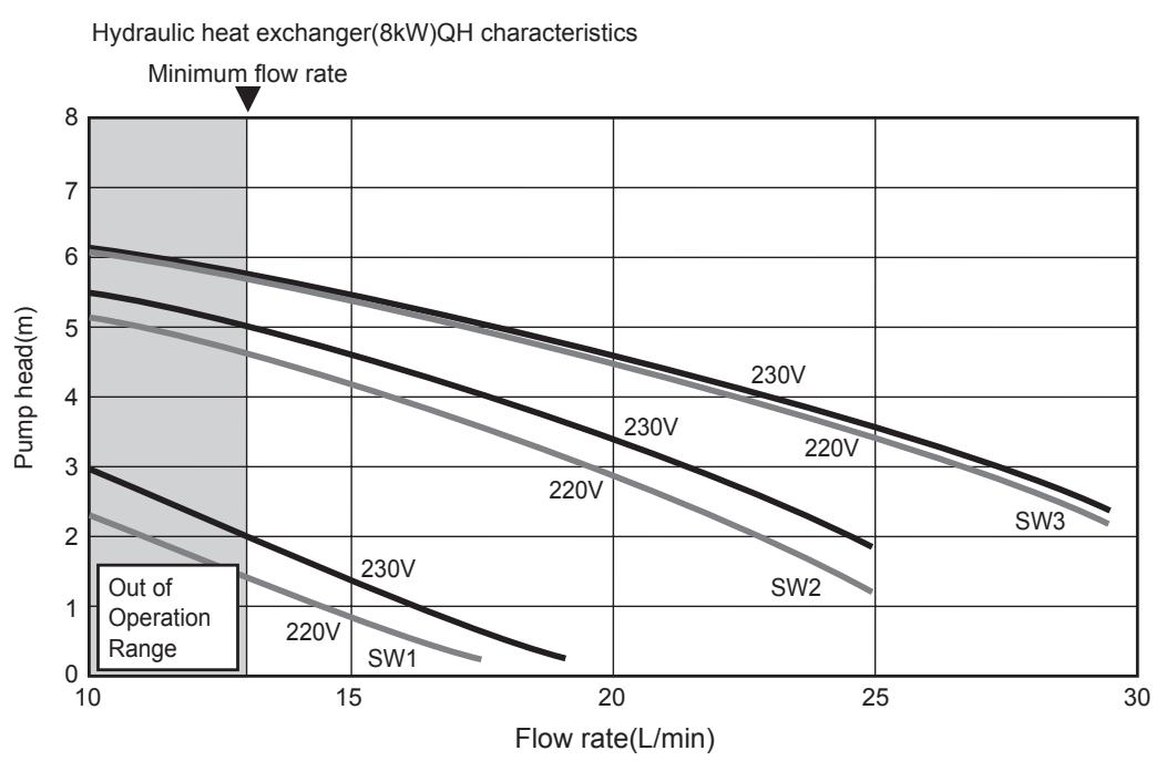
line
| Flow rate(L/min) | Pump head(m) for 220V | Pump head(m) for 230V | Pump head(m) for 230V | Pump head(m) for 220V | Pump head(m) for SW1 | Pump head(m) for SW2 | Pump head(m) for SW3 | | ---------------- | --------------------- | --------------------- | --------------------- | --------------------- | --------------------- | --------------------- | --------------------- | | 10 | 5.0 | 5.5 | 6.0 | 5.5 | 3.0 | 5.0 | 6.0 | | 15 | 1.0 | 1.5 | 2.0 | 1.5 | 0.5 | 1.0 | 1.5 | | 20 | 0.5 | 1.0 | 1.5 | 1.0 | 0.2 | 0.5 | 1.0 | | 25 | 0.2 | 0.5 | 1.0 | 0.5 | 0.1 | 0.2 | 0.5 | | 30 | 0.1 | 0.2 | 0.5 | 0.2 | 0.05 | 0.1 | 0.2 |4-6-2. HWS-1403XWHM3-E, T6-E, D6-E, T9-E
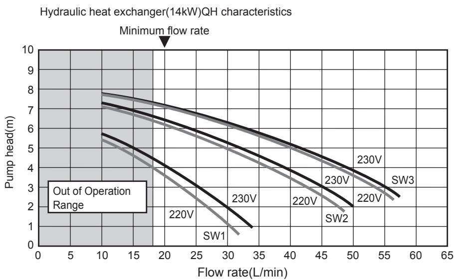
line
| Flow rate(L/min) | Pump head(m) for SW1 | Pump head(m) for SW2 | Pump head(m) for SW3 | Pump head(m) for 220V | Pump head(m) for 230V | | ---------------- | -------------------- | -------------------- | -------------------- | --------------------- | --------------------- | | 10 | 6.0 | 7.5 | 8.0 | 7.0 | 7.5 | | 30 | 1.0 | 2.0 | 3.0 | 4.0 | 5.0 | | 50 | 0.5 | 1.5 | 2.5 | 3.5 | 4.5 | | 60 | 0.2 | 1.0 | 2.0 | 3.0 | 4.0 |4-7. Options
Optional parts
| No. | Part name | Model name | Application | Remarks |
| 1 | External output board | TCB-PCIN3E | Boiler-linked output, Alarm output | Up to two boards (according to applications) |
| Defrost signal output, Compressure operation signal output | ||||
| 2 | External input board | TCB-PCMO3E | Cooling/heating thermostat input | Up to two boards (according to applications) |
| Forced-stop signal input |
▼External output board
Feature
Operation and Error monitoring is possible by using Error output control board "TCB-PCIN3E"
Function / Electric wiring diagram
Alarm output : Output enabled when the system is in alarm / fault condition.
Boiler control output : Output enabled when outdoor ambient temperature <-10 °C
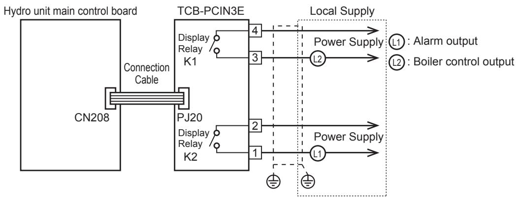
flowchart
graph LR
    A["Hydro unit main control board"] --> B["Connection Cable"]
    B --> C["TCB-PCIN3E"]
    C --> D["Display Relay K1"]
    C --> E["PJ20"]
    C --> F["Display Relay K2"]
    D --> G["Local Supply"]
    E --> G
    F --> G
    G --> H["Power Supply"]
    H --> I["L1: Alarm output"]
    H --> J["L2: Boiler control output"]
Operation output : Display relay is ON with outdoor unit compressor operation.
Defrost output : Display relay is ON when the system in defrost.
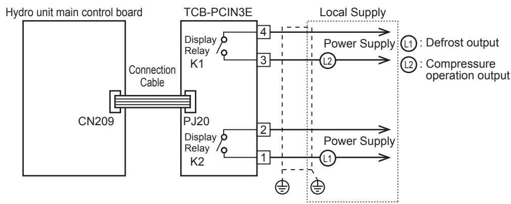
flowchart
graph LR
    A["Hydro unit main control board"] --> B["Connection Cable"]
    B --> C["TCB-PCIN3E"]
    C --> D["Local Supply"]
    D --> E["Power Supply"]
    E --> F["L1: Defrost output"]
    E --> G["L2: Compressure operation output"]
    C --> H["Display Relay K1"]
    C --> I["PJ20 Display Relay K2"]
    C --> J["4"]
    C --> K["3"]
    C --> L["2"]
    C --> M["1"]
    C --> N["Ground"]

CAUTION
- Be sure to prepare a non-voltage point for each terminal.
- Display Relay capacity of "ALERM" and "BOILER", "OPERATION" and "DEFROST"
Below AC230V 0.5A (COS ∅ =100%). when connecting load such as relay coil to "L1,L2" load, insert the noise surge absorber.
Below DC24V 1A (Non-inductive load). when connecting load such as relay coil to "L1,L2" load, insert the bypass circuit.
▼External input board
Feature
* "TCB-PCMO3E" is used for the following external master controls.
- Room thermostat input
- Emergency shutdown input
Refer to "Function/Electric wiring diagram" for feature of each control because connection is different according to the control.
Function / Electric wiring diagram
Room thermostat input
2-3 : Room thermostat input for cooling mode
1-3 : Room thermostat input for heating mode
- Output enabled when either heating or cooling mode selected on room thermostat. (locally procured)
- Volt free details :
- Connection details :
Cooling connection : Terminals 3 (COM) and 2 (COOL) on TCB-BCMO3E (See Schematic below) Heating connection : Terminals 3 (COM) and 1 (HEAT) on TCB-BCMO3E (See Schematic below)
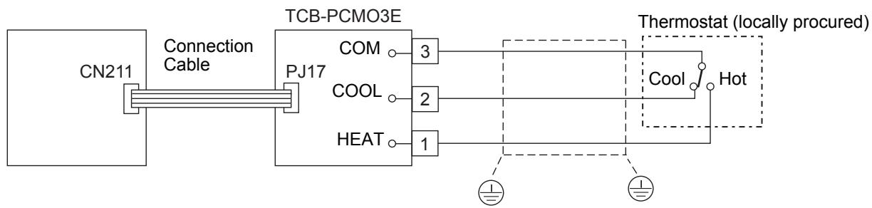
flowchart
graph LR
    A["CN211"] --> B["Connection Cable"]
    B --> C["TCB-PCMO3E"]
    C --> D["COM 3"]
    C --> E["COOL 2"]
    C --> F["HEAT 1"]
    D --> G["Cool"]
    E --> G
    F --> G
    G --> H["Hot"]
    style A fill:#f9f,stroke:#333
    style H fill:#ccf,stroke:#333
Thermostat operation
| Cooling | Heating | |||
| on | off | on | off | |
| 2 - 3 | open | close | - | - |
| 1 - 3 | - | - | close | open |
Emergency shutdown input
S2 : Emergency stop input
• Non-voltage contacts
- Connection details :
Emergency stop : Terminals 3 (COM) and 1 (HEAT) on TCB-PCMO3E (See Schematic below)
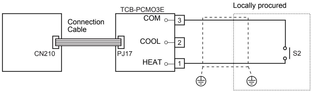

CAUTION
- Be sure to prepare non voltage continuous point of contact for each terminal.
- Supplementary Insulation must be added to user touched to user touchabel part of switches.
5. OUTDOOR UNIT
5-1. Specification
5-1-1. Outdoor unit specifications
| Outdoor unit | HWS-803H-E | HWS-1103H-E | HWS-1403H-E | ||
| Power supply | 1 ~ 220-230V 50Hz | ||||
| Compressor | Type | Twin rotary type with DC-Inverter variable speed control | |||
| Motor Output | kW | 2.0 | 3.75 | ||
| Pole | 4 | ||||
| Refrigerant charged | 1.8 | 2.7 | |||
| Refrigerant control | Pulse motor valve | ||||
| Pipe length | Minimum | m | 5 | ||
| Maximum | m | 30 | |||
| Height difference | Outdoor-Hydro unit | m | 30 | ||
| Appearance | Color | Silky shade (Muncel 1Y8.5-0.5) | |||
| Material | PCM | ||||
| Outer dimension | Height | mm | 890 | 1340 | |
| Width | mm | 900 | 900 | ||
| Depth | mm | 320 | 320 | ||
| Unit weight | kg | 63 | 93 | ||
| Packing dimension | Height | mm | 975 | 1425 | |
| Width | mm | 971 | 971 | ||
| Depth | mm | 436 | 436 | ||
| Total weight | unit and packing | kg | 69 | 100 | |
| Heat exchanger | Type | Finned tube | |||
| Fan unit | Fan | Propeller fan | |||
| Standard air flow | m^3/min | 57 | 101 | 103 | |
| Motor | W | 63 | 100+100 | ||
| Bottom plate heater | W | - | - | - | |
| Sound pressure level | Heating normal | dBA | 49 | 49 | 51 |
| Heating low noise* | dBA | 42 | 44 | 44 | |
| Cooling normal | dBA | 47 | 50 | 51 | |
| Cooling low noise* | dBA | 44 | 45 | 45 | |
| Hot water normal | dBA | 49 | 49 | 51 | |
| Hot water low noise | dBA | 42 | 44 | 44 | |
| Operation outdoor temp | Heating | °C | -20 to 25 | ||
| Cooling | °C | 10 to 43 | |||
| Hot water | °C | -20 to 43 | |||
| Refrigerant pipe | Gas | mm | 15.9 | ||
| Liquid | mm | 9.5 | |||
| Outdoor unit | HWS-1103H8-EHWS-1103H8R-E | HWS-1403H8-EHWS-1403H8R-E | HWS-1603H8-EHWS-1603H8R-E | ||
| Power supply | 3N ~ 380-400V 50Hz | ||||
| Compressor | Type | Twin rotary type with DC-Inverter variable speed control | |||
| Motor Output | kW | 3.75 | |||
| Pole | 4 | ||||
| Refrigerant charged | 2.7 | ||||
| Refrigerant control | Pulse motor valve | ||||
| Pipe length | Minimum | m | 5 | ||
| Maximum | m | 30 | |||
| Height difference | Outdoor-Hydro unit | m | 30 | ||
| Appearance | Color | Silky shade (Muncel 1Y8.5-0.5) | |||
| Material | PCM | ||||
| Outer dimension | Height | mm | 1340 | ||
| Width | mm | 900 | |||
| Depth | mm | 320 | |||
| Unit weight | kg | 93 | |||
| Packing dimension | Height | mm | 1425 | ||
| Width | mm | 971 | |||
| Depth | mm | 436 | |||
| Total weight | unit and packing | kg | 100 | ||
| Heat exchanger | Type | Finned tube | |||
| Fan unit | Fan | Propeller fan | |||
| Standard air flow | m^3/min | 101 | 103 | ||
| Motor | W | 100+100 | |||
| Bottom plate heater | W | - | - | - | |
| Sound pressure level | Heating normal | dBA | 49 | 51 | 52 |
| Heating low noise* | dBA | 44 | 44 | 44 | |
| Cooling normal | dBA | 50 | 51 | 52 | |
| Cooling low noise* | dBA | 45 | 45 | 45 | |
| Hot water normal | dBA | 49 | 51 | 52 | |
| Hot water low noise | dBA | 44 | 44 | 44 | |
| Operation outdoor temp | Heating | °C | -20 to 25 | ||
| Cooling | °C | 10 to 43 | |||
| Hot water | °C | -20 to 43 | |||
| Refrigerant pipe | Gas | mm | 15.9 | ||
| Liquid | mm | 9.5 | |||
| Outdoor unit | HWS-1103H8R-E | HWS-1403H8R-E | HWS-1603H8R-E | ||
| Power supply | 3N ~ 380-400V 50Hz | ||||
| Compressor | Type | Twin rotary type with DC-Inverter variable speed control | |||
| Motor Output | kW | 3.75 | |||
| Pole | 4 | ||||
| Refrigerant charged | 2.7 | ||||
| Refrigerant control | Pulse motor valve | ||||
| Pipe length | Minimum | m | 5 | ||
| Maximum | m | 30 | |||
| Height difference | Outdoor-Hydro unit | m | 30 | ||
| Appearance | Color | Silky shade (Muncel 1Y8.5-0.5) | |||
| Material | PCM | ||||
| Outer dimension | Height | mm | 1340 | ||
| Width | mm | 900 | |||
| Depth | mm | 320 | |||
| Unit weight | kg | 93 | |||
| Packing dimension | Height | mm | 1425 | ||
| Width | mm | 971 | |||
| Depth | mm | 436 | |||
| Total weight | unit and packing | kg | 100 | ||
| Heat exchanger | Type | Finned tube | |||
| Fan unit | Fan | Propeller fan | |||
| Standard air flow | m^3/min | 101 | 103 | ||
| Motor | W | 100+100 | |||
| Bottom plate heater | W | 75 | 75 | 75 | |
| Sound pressure level | Heating normal | dBA | 49 | 51 | 52 |
| Heating low noise* | dBA | 44 | 44 | 44 | |
| Cooling normal | dBA | 50 | 51 | 52 | |
| Cooling low noise* | dBA | 45 | 45 | 45 | |
| Hot water normal | dBA | 49 | 51 | 52 | |
| Hot water low noise | dBA | 44 | 44 | 44 | |
| Operation outdoor temp | Heating | °C | -20 to 25 | ||
| Cooling | °C | 10 to 43 | |||
| Hot water | °C | -20 to 43 | |||
| Refrigerant pipe | Gas | mm | 15.9 | ||
| Liquid | mm | 9.5 | |||
5-2. Dimension 5-2-1. HWS-803H-E
Unit: mm
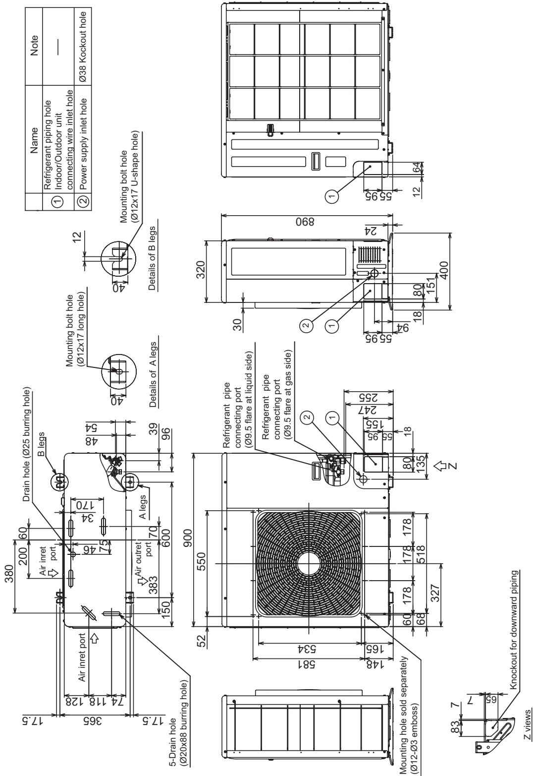
5-2-2. HWS-1103H-E, HWS-1403H-E, HWS-1603H-E HWS-1103H(R)-E, HWS-1403H(R)-E, HWS-1603H(R)-E
Unit: mm
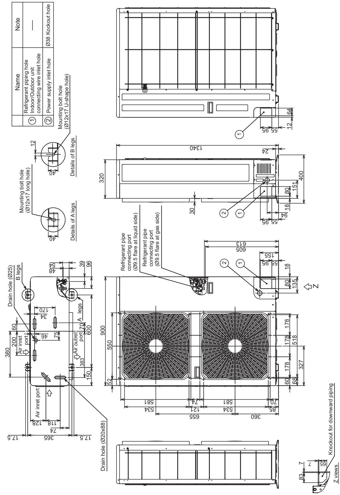
5-3. Piping Diagram
Outdoor unit
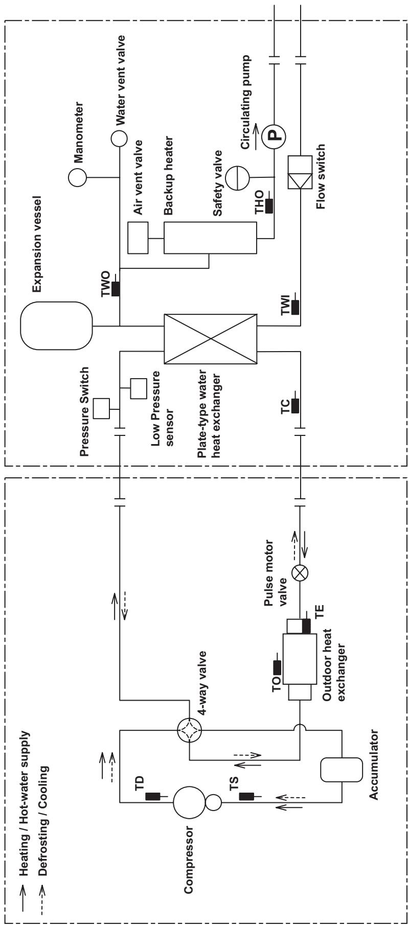
flowchart
graph TD
    A["Heating / Hot-water supply"] --> B["Compressor"]
    C["Defrosting / Cooling"] --> D["Accumulator"]
    B --> E["4-way valve"]
    D --> F["TO"]
    D --> G["TS"]
    D --> H["TO"]
    D --> I["TE"]
    D --> J["Pulse motor valve"]
    J --> K["Outdoor heat exchanger"]
    K --> L["Accumulator"]
    M["Expansion vessel"] --> N["TWO"]
    N --> O["Pressure Switch"]
    O --> P["Low Pressure sensor"]
    P --> Q["Plate-type water heat exchanger"]
    Q --> R["Flow switch"]
    S["Flow switch"] --> T["THO"]
    T --> U["Safety valve"]
    U --> V["Air vent valve"]
    V --> W["Backup heater"]
    W --> X["Water vent valve"]
    X --> Y["Manometer"]
    Y --> Z["Circulating pump"]
5-4. Wiring Diagram
5-4-1. Outdoor Unit (Single phase type)
▼HWS-803H-E, HWS-1103H-E, HWS-1403H-E
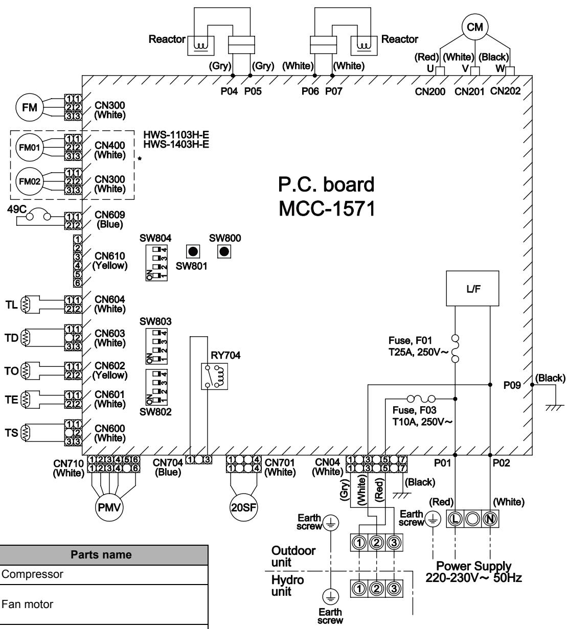
flowchart
graph TD
    A["PMV"] --> B["CN710 (White)"]
    A --> C["CN600 (White)"]
    A --> D["CN601 (White)"]
    A --> E["CN602 (Yellow)"]
    A --> F["CN603 (White)"]
    A --> G["CN604 (White)"]
    A --> H["CN610 (Yellow)"]
    A --> I["CN609 (Blue)"]
    J["PMV"] --> K["CN704 (Blue)"]
    J --> L["CN701 (White)"]
    M["PMV"] --> N["CN803"]
    O["PMV"] --> P["CN802"]
    Q["PMV"] --> R["CN804"]
    S["PMV"] --> T["CN801"]
    U["PMV"] --> V["CN804"]
    W["PMV"] --> X["CN803"]
    Y["PMV"] --> Z["CN802"]
    AA["PMV"] --> AB["CN804"]
    AC["PMV"] --> AD["CN803"]
    AE["PMV"] --> AF["CN802"]
    AG["PMV"] --> AH["CN804"]
    AI["PMV"] --> AJ["CN803"]
    AK["PMV"] --> AL["CN802"]
    AM["PMV"] --> AN["CN804"]
    AO["PMV"] --> AP["CN803"]
    AQ["PMV"] --> AR["CN802"]
    AS["PMV"] --> AT["CN804"]
    AU["PMV"] --> AV["CN803"]
    AW["PMV"] --> AX["CN802"]
    AY["PMV"] --> AZ["CN804"]
    BA["PMV"] --> BB["CN803"]
    BC["PMV"] --> BD["CN802"]
    BE["PMV"] --> BF["CN804"]
    BG["PMV"] --> BH["CN803"]
    BI["PMV"] --> BJ["CN802"]
    BK["PMV"] --> BL["CN804"]
    BM["PMV"] --> BN["CN803"]
    BO["PMV"] --> BP["CN802"]
    BQ["PMV"] --> BR["CN804"]
    BS["PMV"] --> BT["CN803"]
    BU["Fuse, F01 T25A, 250V~"] --> BV["L/F"]
    BW["Fuse, F03 T10A, 250V~"] --> BX["Fuse, F01 T25A, 250V~"]
    BY["Fuse, F03 T10A, 250V~"] --> BZ["Fuse, F01 T25A, 250V~"]
    CA["Fuse, F03 T10A, 250V~"] --> CB["Fuse, F01 T25A, 250V~"]
    CC["Fuse, F03 T10A, 250V~"] --> CD["Fuse, F01 T25A, 250V~"]
    CE["Fuse, F03 T10A, 250V~"] --> CF["Fuse, F01 T25A, 250V~"]
    DG["Fuse, F03 T10A, 250V~"] --> DH["Fuse, F01 T25A, 250V~"]
    DI["Fuse, F03 T10A, 250V~"] --> DJ["Fuse, F01 T25A, 250V~"]
    DK["Fuse, F03 T10A, 250V~"] --> DL["Fuse, F01 T25A, 250V~"]
    DM["Fuse, F03 T10A, 250V~"] --> DE["Fuse, F01 T25A, 250V~"]
    DF["Fuse, F03 T10A, 250V~"] --> DG
    DG["Fuse, F01 T25A, 250V~"] --> DG
    DG["Fuse, F03 T10A, 250V~"] --> DG
    DG["Fuse, F01 T25A, 250V~"] --> DV["Fuse, F03 T10A, 250V~"]
    DW["Fuse, F03 T10A, 250V~"] --> DX["Fuse, F01 T25A, 250V~"]
    DX["Fuse, F03 T10A, 250V~"] --> DX
    DX["Fuse, F01 T25A, 250V~"] --> DX
    DX["Fuse, F03 T10A, 250V~"] --> DX
    DX["Fuse, F01 T25A, 250V~"] --> DX
    DX["Fuse, F03 T10A, 250V~"] --> DX
    DX["Fuse, F01 T25A, 250V~"] --> DX
    DX["Fuse, F01 T25A, 250V~"] --> DX
    DX["Fuse, F03 T10A, 250V~"] --> DX
    DX["Fuse, F01 T25A, 250V~"] --> DX
    DX["Fuse, F03 T10A, 250V ~ 5Hz Power Supply 220-230V ~ 5Hz"]
| Symbol | Parts name |
| CM | Compressor |
| FM | Fan motor |
| FM01,02* | |
| PMV | Pulse motor valve |
| TD | Pipe temperature sensor (Discharge) |
| TS | Pipe temperature sensor (Suction) |
| TE | Heat exchanger sensor 1 |
| TL | Heat exchanger sensor 2 |
| TO | Outside temperature sensor |
| 20SF | 4-way valve coil |
| 49C | Compressor case thermostat |
| RY | Relay |
| L/F | Line Filter |
- ◎ indicates the terminal block. Alphanumeric characters in the cycle indicate the terminal No.
- The two-dot chain line indicates the wiring procured locally.
- □ indicates the P.C. board.
- For the hydro unit circuit, refer to the wiring diagram of the hydro unit.
5-4-2. Outdoor unit (3 phase type)
▼HWS-1103H8(R)-E, -1403H8(R)-E, -1603H8(R)-E
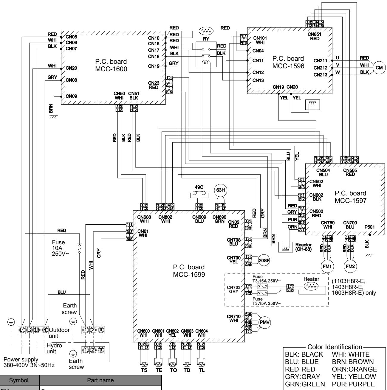
| Symbol | Part name |
| CM | Compressor |
| FM1,2 | Fan motor |
| PMV | Pulse motor valve |
| TD | Pipe temperature sensor (Discharge) |
| TS | Pipe temperature sensor (Suction) |
| TE | Heat exchanger sensor 1 |
| TL | Heat exchanger sensor 2 |
| TO | Outside temperature sensor |
| 20SF | 4-way valve coil |
| 49C | Compressor case thermostat |
| 63H | High-pressure switch |
| RY | Relay |
*HWS-1103H-E, HWS-1403H-E
- ◎ indicates the terminal block. Alphanumeric characters in the cycle indicate terminal No.
- The two-dot chain line indicates the wiring procured locally.
- □ indicates the P.C. board.
- For the hydro unit circuit, refer to the wiring diagram of the indoor unit.
5-4-3. Power line
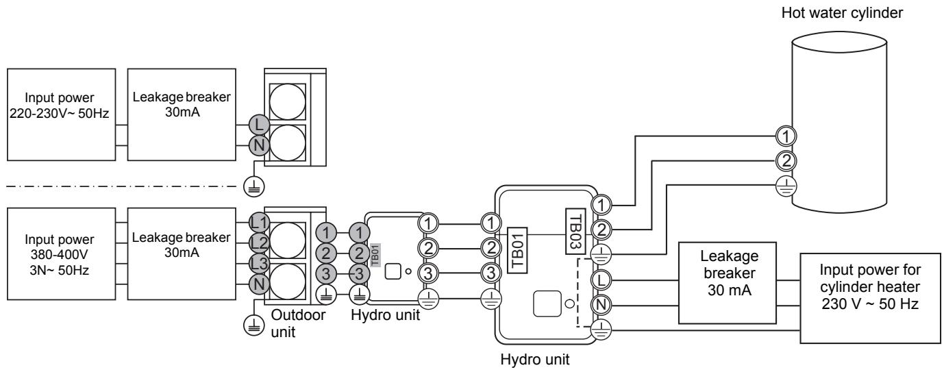
flowchart
graph LR
    A["Input power 220-230V~50Hz"] --> B["Leakage breaker 30mA"]
    C["Input power 380-400V 3N~50Hz"] --> D["Leakage breaker 30mA"]
    B --> E["Outdoor unit L1"]
    D --> F["Outdoor unit L2"]
    D --> G["Outdoor unit L3"]
    D --> H["Outdoor unit N"]
    E --> I["Hydro unit 1"]
    F --> J["Hydro unit 2"]
    G --> K["Hydro unit 3"]
    H --> L["Hydro unit 1"]
    I --> M["TB01"]
    J --> N["TB01"]
    K --> O["TB01"]
    L --> P["TB01"]
    M --> Q["TB03"]
    N --> R["TB03"]
    O --> S["TB03"]
    P --> T["TB03"]
    Q --> U["TB03"]
    R --> V["Hot water cylinder"]
    S --> W["Hot water cylinder"]
    T --> X["Hot water cylinder"]
    U --> Y["Input power for cylinder heater 230 V~50 Hz"]
    V --> Z["Input power for cylinder heater 230 V~50 Hz"]
5-4-4. Wiring between Hydro Unit and Outdoor Unit
▼ HWS-803H-E, HWS-1103H-E, HWS-1403H-E
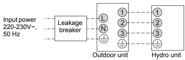
flowchart
graph LR
    A["Input power 220-230V~, 50 Hz"] --> B["Leakage breaker"]
    B --> C["Outdoor unit"]
    C --> D["Hydro unit"]
    C --> E["1"]
    C --> F["2"]
    C --> G["3"]
    C --> H["1"]
    C --> I["2"]
    C --> J["3"]
▼ HWS-1103H8-E, H8R-E
HWS-1403H8-E, H8R-E
HWS-1603H8-E, H8R-E
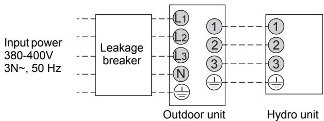
flowchart
graph LR
    A["Input power 380-400V 3N~, 50 Hz"] --> B["Leakage breaker"]
    B --> C["Outdoor unit"]
    C --> D["Hydro unit"]
    subgraph Outdoor unit
        L1["L1"] --> 1["1"]
        L2["L2"] --> 2["2"]
        L3["L3"] --> 3["3"]
        N["N"] --> 1
        I["I"] --> 2
        J["I"] --> 3
    end
▼ HWS-803H-E, HWS-1103H-E, HWS-1403H-E
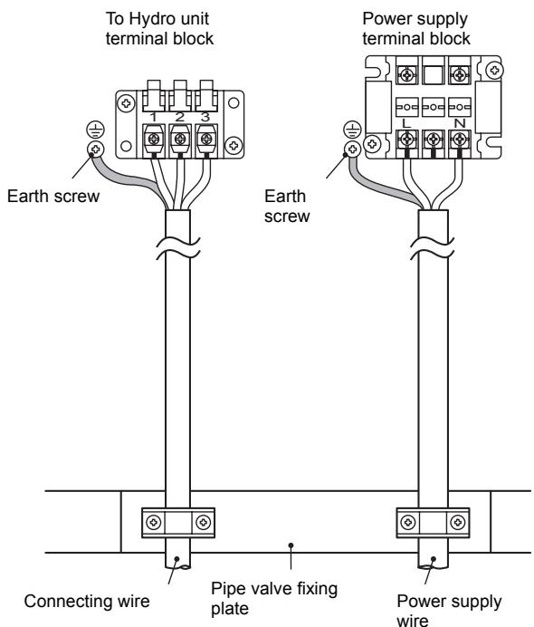
Stripping length power cord and connecting wire
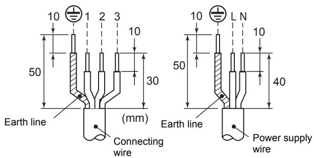
▼ HWS-1103H8-E, H8R-E
HWS-1403H8-E, H8R-E
HWS-1603H8-E, H8R-E
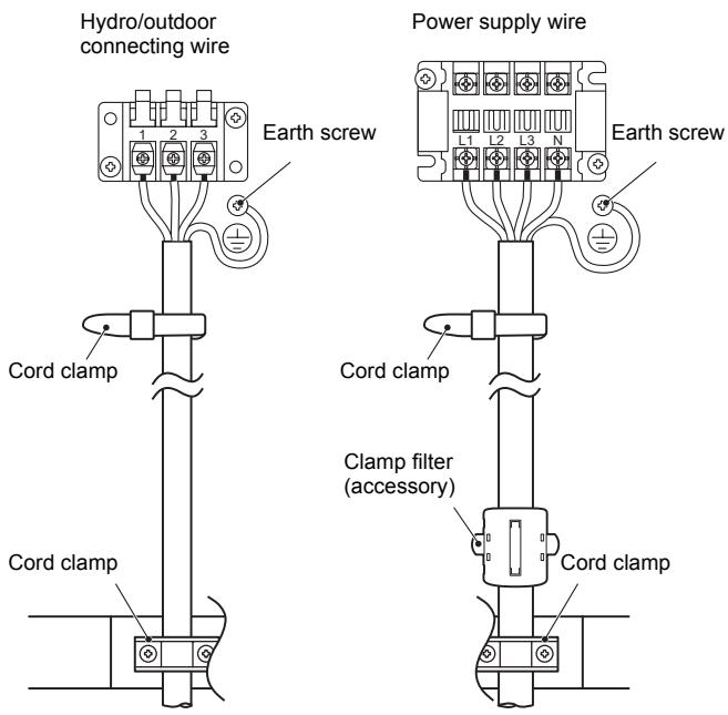
Stripping length power cord and connecting wire
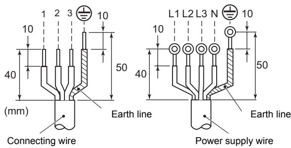
5-5. Sound Data
5-5-1. Sound pressure level measurement
▼HWS-803H-E
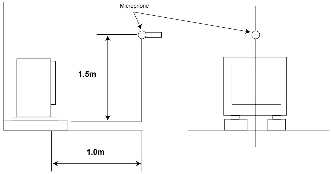
▼HWS-1103H-E, HWS-1403H-E, HWS-1103H8(R)-E, HWS-1403H8(R)-E, HWS-1603H8(R)-E
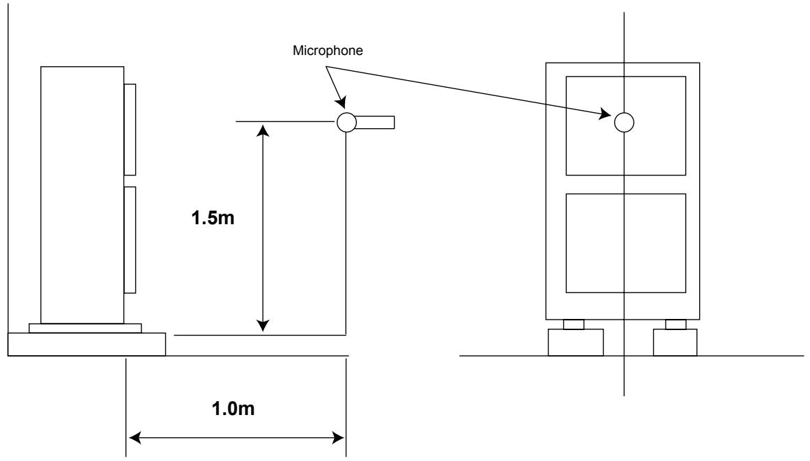
5-5-2. Sound Characteristics (NC Curve)
▼HWS-803H-E
(8 kw, 230 V \~ 50Hz)
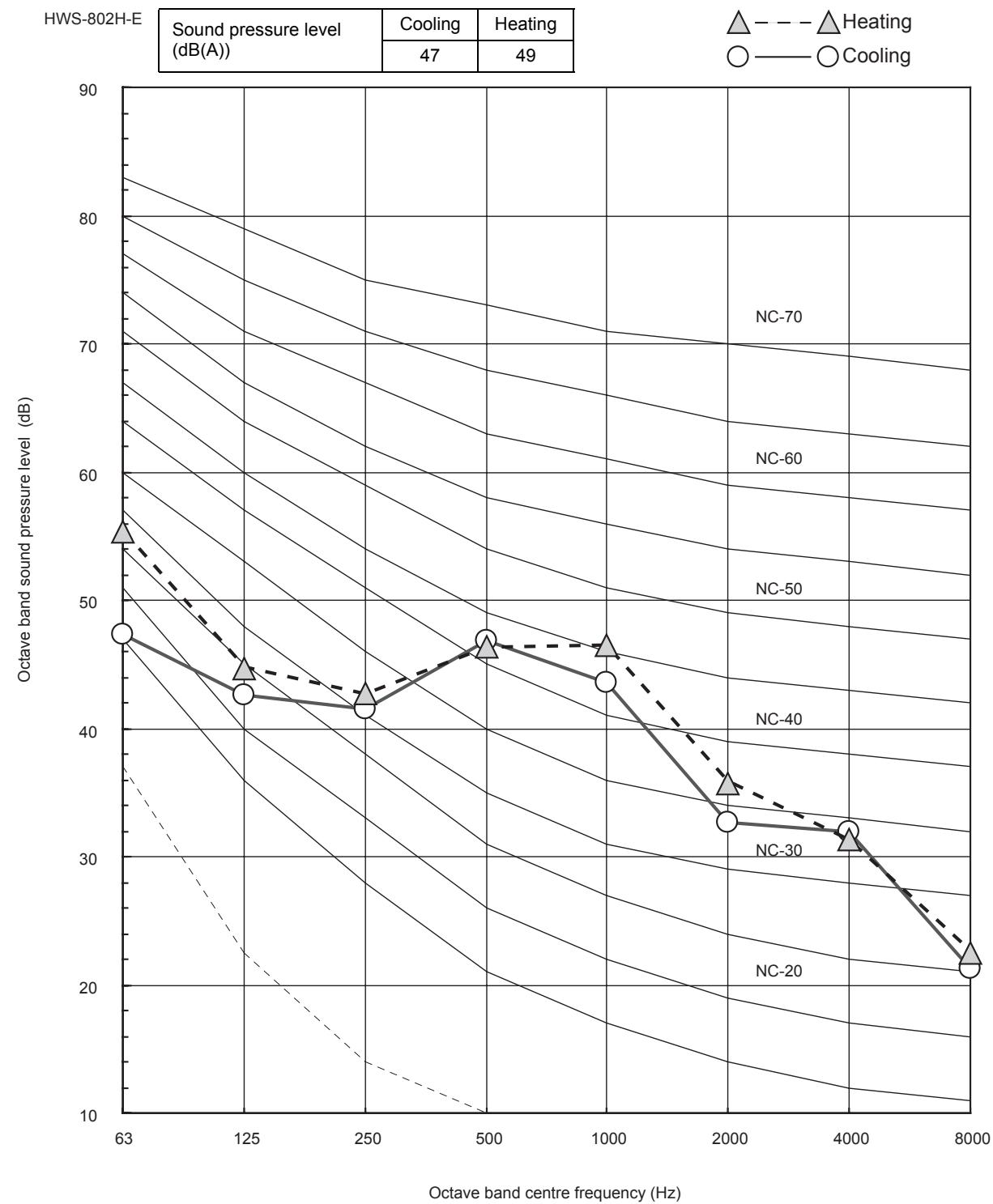
line
| Octave band centre frequency (Hz) | Cooling (dB(A)) | Heating (dB(A)) | Cooling (dB(A)) | Heating (dB(A)) | | ---------------------------------- | --------------- | --------------- | --------------- | --------------- | | 63 | 47 | 49 | 47 | 49 | | 125 | 47 | 49 | 43 | 49 | | 250 | 47 | 49 | 42 | 49 | | 500 | 47 | 49 | 47 | 49 | | 1000 | 47 | 49 | 44 | 49 | | 2000 | 47 | 49 | 33 | 49 | | 4000 | 47 | 49 | 32 | 49 | | 8000 | 47 | 49 | 22 | 49 |▼HWS-1103H-E, 1103H8(R)-E
(11 kw, 380-400V 3N\~50Hz)
HWS-1103H8-E
| Sound pressure level (dB(A)) | Cooling | Heating |
| 51 | 51 |


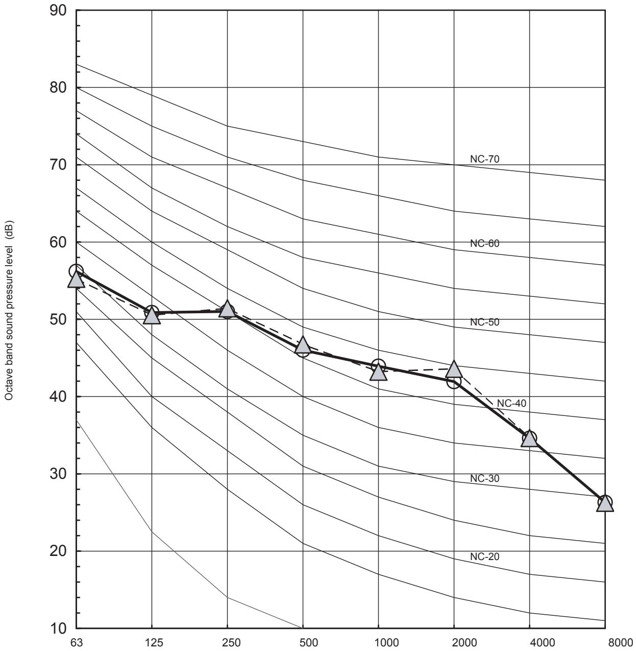
line
| Octave band sound pressure level (dB) | NC-20 | NC-30 | NC-40 | NC-50 | NC-60 | NC-70 | | ------------------------------------- | ----- | ----- | ----- | ----- | ----- | ----- | | 63 | 10 | 15 | 20 | 25 | 30 | 35 | | 125 | 15 | 20 | 25 | 30 | 35 | 40 | | 250 | 20 | 25 | 30 | 35 | 40 | 45 | | 500 | 25 | 30 | 35 | 40 | 45 | 50 | | 1000 | 30 | 35 | 40 | 45 | 50 | 55 | | 2000 | 35 | 40 | 45 | 50 | 55 | 60 | | 4000 | 40 | 45 | 50 | 55 | 60 | 65 | | 8000 | 45 | 50 | 55 | 60 | 65 | 70 |Octave band centre frequency (Hz)
▼HWS-1403H-E, 1403H8(R)-E
(14kw, 380-400V 3N\~50Hz)
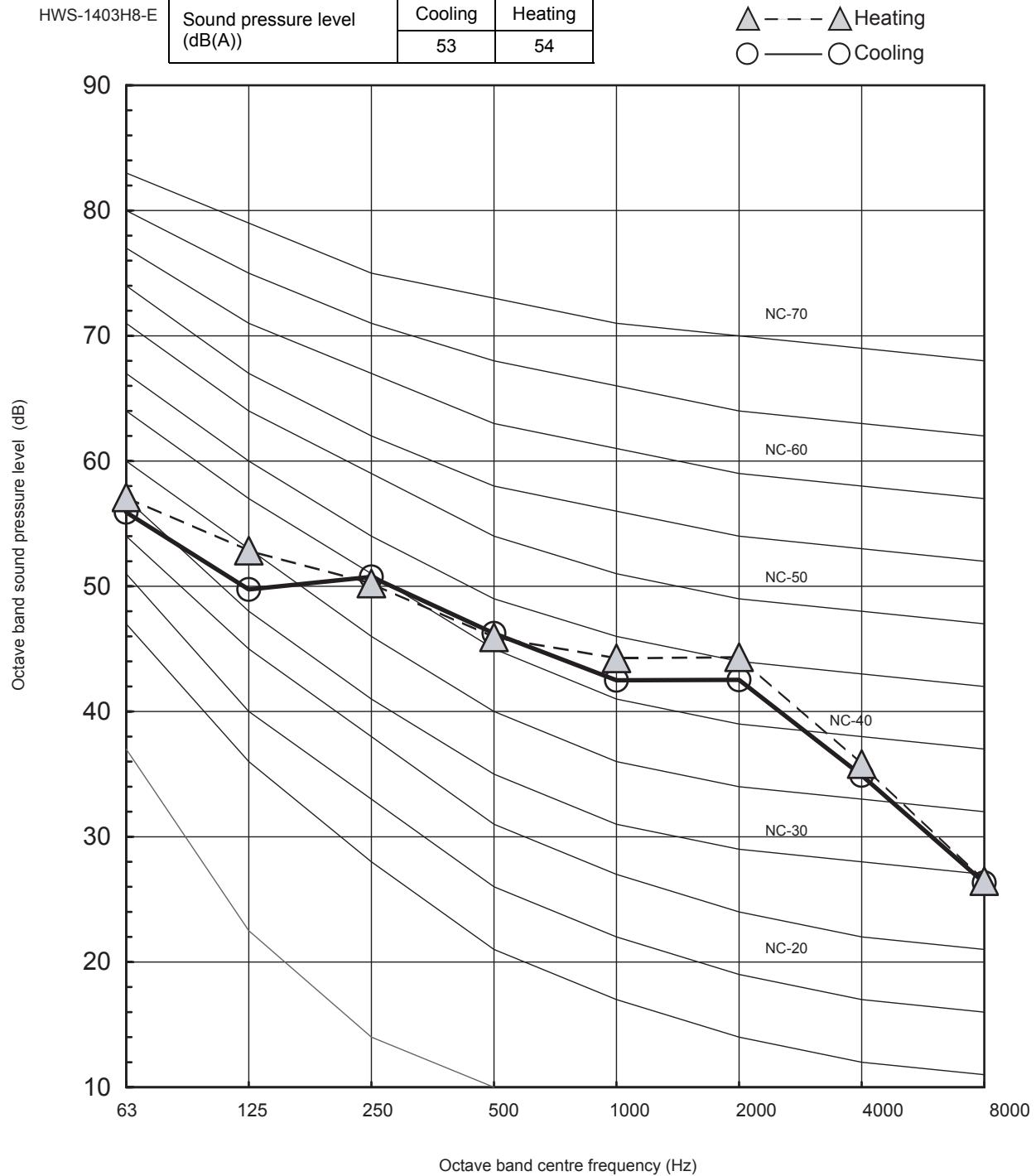
line
| Octave band centre frequency (Hz) | Cooling (dB(A)) | Heating (dB(A)) | | --------------------------------- | --------------- | --------------- | | 63 | 53 | 54 | | 125 | 53 | 50 | | 250 | 53 | 51 | | 500 | 53 | 46 | | 1000 | 53 | 43 | | 2000 | 53 | 43 | | 4000 | 53 | 35 | | 8000 | 53 | 26 |▼HWS-1603H8(R)-E
(16kw, 380-400V 3N\~50Hz)
HWS-1603H8-E
| Sound pressure level (dB(A)) | Cooling | Heating |
| 52 | 52 |
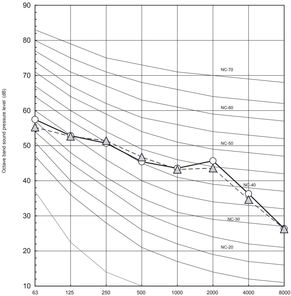
line
| Octave band sound pressure level (dB) | NC-20 | NC-30 | NC-40 | NC-50 | NC-60 | NC-70 | | ------------------------------------ | ----- | ----- | ----- | ----- | ----- | ----- | | 63 | 10 | 15 | 20 | 25 | 30 | 35 | | 125 | 15 | 20 | 25 | 30 | 35 | 40 | | 250 | 20 | 25 | 30 | 35 | 40 | 45 | | 500 | 25 | 30 | 35 | 40 | 45 | 50 | | 1000 | 30 | 35 | 40 | 45 | 50 | 55 | | 2000 | 35 | 40 | 45 | 50 | 55 | 60 | | 4000 | 40 | 45 | 50 | 55 | 60 | 65 | | 8000 | 45 | 50 | 55 | 60 | 65 | 70 |Octave band centre frequency (Hz)
5-6. Operation Range
8 kW class
Cooling operation
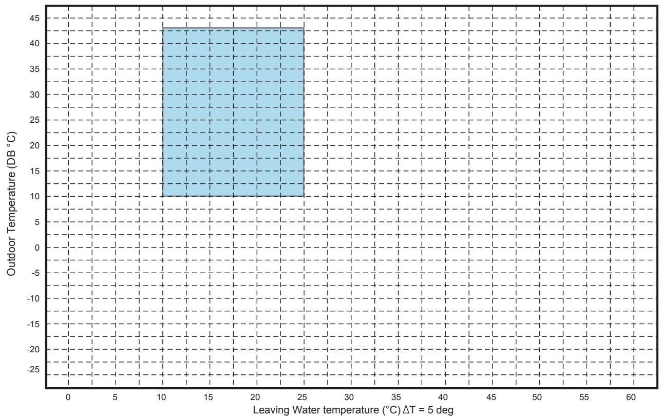
bar
| Leaving Water Temperature (°C) ΔT = 5 deg | Outdoor Temperature (DB °C) | |---|---| | 10 | 43 | | 25 | 43 |Heating and hot water operation
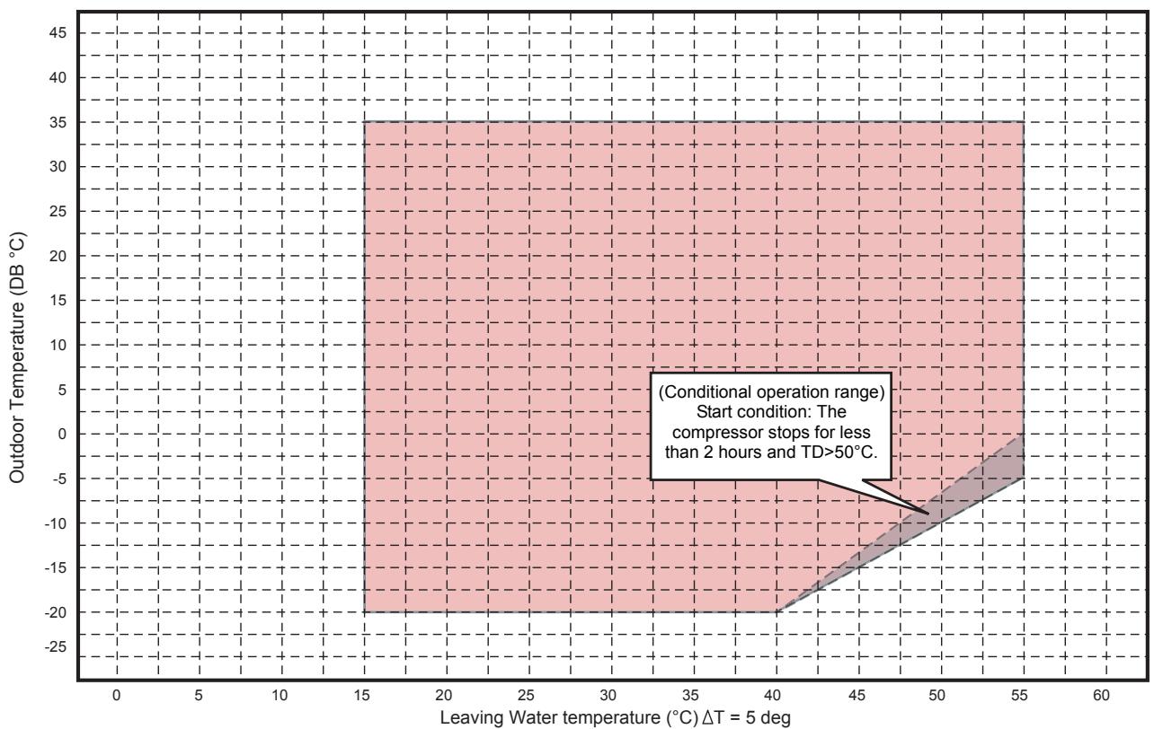
area
| Leaving Water temperature (°C) | Outdoor Temperature (DB °C) | | ------------------------------ | -------------------------- | | 15 | 35 | | 40 | -20 | | 55 | 35 |11, 14, 16 kW class
Cooling operation
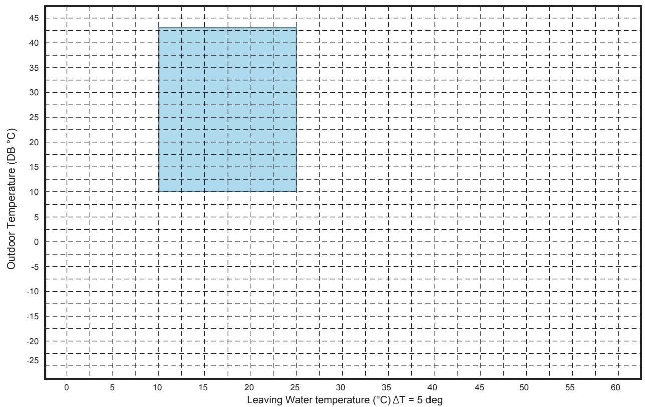
bar
| Outdoor Temperature (DB °C) | Leaving Water Temperature (°C) ΔT = 5 deg | | :--- | :--- | | 43 | 10 | | 43 | 25 |Heating and hot water operation
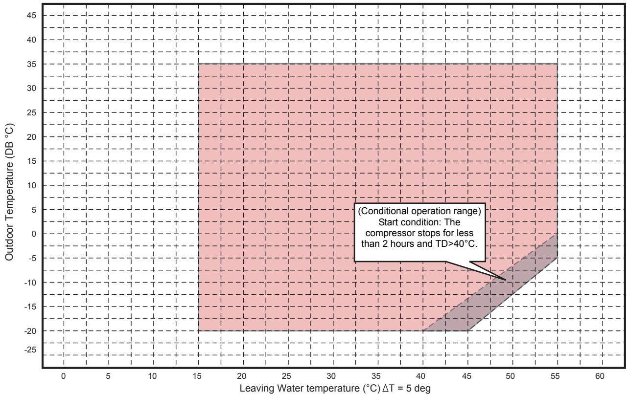
area
| Leaving Water temperature (°C) | Outdoor Temperature (DB °C) | | ------------------------------ | -------------------------- | | 15 | 35 | | 40 | -20 | | 55 | 35 |NOTE
Hot water produced only by cylinder heater when both cooling and hot water operation demanded.
6. HOT WATER CYLINDER
6-1. Specification
Hot water cylinder specifications
| Hot water cylinder | HWS-1501 CSHM3-E | HWS-2101 CSHM3-E | HWS-3001 CSHM3-E | HWS-1501 CSHM3-UK | HWS-2101 CSHM3-UK | HWS-3001 CSHM3-UK | ||
| Water volume | litres | 150 | 210 | 300 | 150 | 210 | 300 | |
| Appearance | Color | White | ||||||
| Material | Plastic coated steel | |||||||
| Cylinder | Material | Stainless steel | ||||||
| Insulation | Material | Flame retardant expanded polyurethane foam | ||||||
| Thickness | mm | 50 | ||||||
| Heat exchanger | Material | Stainless steel tube | ||||||
| Immersion heater | Type | Single straight, Alloy 825 sheathed | ||||||
| Capacity | kW | 2.75 | ||||||
| Outer dimension | Height | mm | 1,090 | 1,474 | 2,040 | 1,090 | 1,474 | 2,040 |
| Diameter | mm | 550 | ||||||
| Unit weight | kg | 31 | 41 | 59 | 31 | 41 | 56 | |
| Packing dimension | Height | mm | 1,213 | 1,781 | 2,118 | 1,406 | 1,781 | 2,118 |
| Width | mm | 576 | ||||||
| Depth | mm | 640 | ||||||
| Total weight | unit and packing | kg | 37 | 44 | 59 | 41 | 51 | 56 |
| Maximum water temperature | °C | 75 | ||||||
| Maximum water pressure | bar | 10 | ||||||
| Water pipe Hydro-cylinder | Inlet | mm | 22 | |||||
| Outlet | mm | 22 | ||||||
| Water pipe Domestic water-cylinder | Inlet | mm | 22 | |||||
| Outlet | mm | 22 | ||||||
| Standard accessories | Expansion Vessel | litres | Not included | 12 | 18 | 25 | ||
| Installation manual | Installation manual | |||||||
| Safety group NF7bar | Factory fitted T&P valve c/w insulation and housing | |||||||
| Compression nuts and olives | Compression nuts and olives | |||||||
| Cylinder heater key spanner | Cylinder heater key spanner | |||||||
| Tundish | ||||||||
| Cold water combination valve | ||||||||
6-2. Dimension
General dimensions and performance
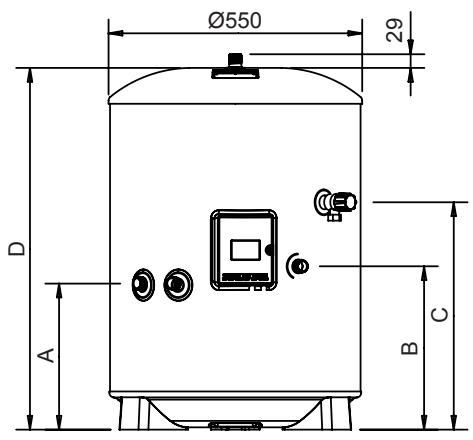

| MODEL | HWS-1501CSHM3-EHWS-1501CSHM3-UK | HWS-2101CSHM3-EHWS-2101CSHM3-UK | HWS-3001CSHM3-EHWS-3001CSHM3-UK |
| NOMINAL CAPACITY (litres) | 150 | 210 | 300 |
| A (mm) | 315 | 315 | 315 |
| B (mm) | 354 | 354 | 354 |
| C (mm) | 800 | 1184 | 1474 |
| D (mm) | 1090 | 1474 | 2040 |
| SURFACE AREA (sq.m) | 0.65 | 0.79 | 0.79 |
| HOT WATER OUTPUT AT 60°C (litres) | 102 | 163 | 254 |
| MIXED HOT WATER OUTPUT AT 40°C (litres) | 243 | 329.5 | 476 |
| HEATLOSS (kWh/24h) | 1.45 | 1.91 | 2.52 |
| HEATING TIME 15°C TO 60°C - USING ELECTRIC CYLINDER HEATER ONLY (mins) | 123 | 188 | 262 |
| CAPACITY HEATED USING ELECTRIC CYLINDER HEATER ONLY (litres) | 102 | 163 | 254 |
6-3. Piping Diagram
▼HWS-1501CSHM3-E, HWS-2101CSHM3-E, HWS-3001CAHM3-E
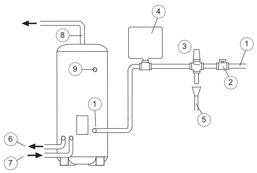
① COLD WATER INLET
② ISOLATING VALVE
(3) SAFETY GROUP NF7 BAR
④ SANITARY WATER EXPANSION VESSEL
⑤ DISCHARGE PIPE
6 PRIMARY CIRCUIT RETURI
⑦ PRIMARY CIRCUIT FLOW
⑧ HOT WATER OUTLET
⑨ SANITARY WATERRE-CIRCULATION CONNECTION
▼HWS-1501CSHM3-UK, HWS-2101CSHM3-UK, HWS-3001CSHM3-UK
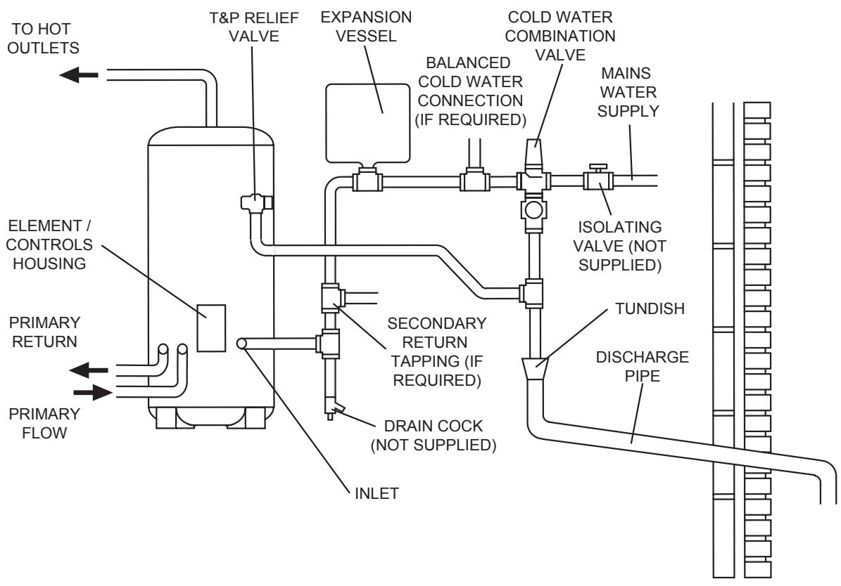
flowchart
graph TD
    A["TO HOT OUTLETS"] --> B["T&P RELIEF VALVE"]
    B --> C["EXPANSION VESSEL"]
    C --> D["BALANCED COLD WATER CONNECTION (IF REQUIRED)"]
    D --> E["COLD WATER COMBINATION VALVE"]
    E --> F["MAINS WATER SUPPLY"]
    F --> G["ISOLATING VALVE (NOT SUPPLIED)"]
    G --> H["TUNDISH"]
    H --> I["DISCHARGE PIPE"]
    I --> J["INLET"]
    J --> K["DRAIN COCK (NOT SUPPLIED)"]
    K --> L["SECONDARY RETURN TAPPING (IF REQUIRED)"]
    L --> M["PRIMARY RETURN"]
    M --> N["ELEMENT / CONTROLS HOUSING"]
    N --> O["PRIMARY FLOW"]
Typical discharge pipe arrangement (extract from Building Regulation G3 Guidance section 3.9)
Safety device
(e.g. Temperaturerelief valve)
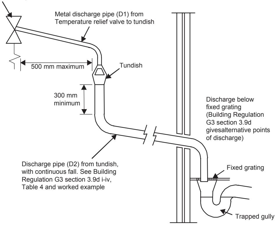
6-4. Wiring Diagram
▼HWS-1501CSHM3-E, HWS-2101CSH3-E, HWS-3001CSHM3-E HWS-1501CSHM3-UK, HWS-2101CSHM3-UK, HWS-3001CSHM3-UK Electrical Connections (Schematic)
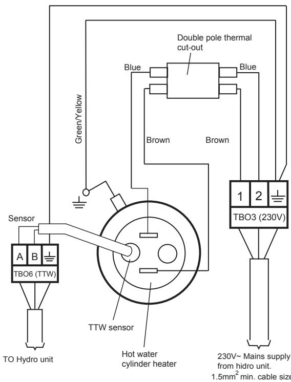
Thermal cut-out
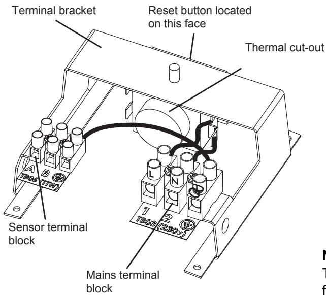
NOTE:
The cover and element assembly have been removed from this view for clarity
7. HYDRO UNIT INSTALLATION MANUAL
Hydro Unit
Model name:
HWS-803XWHM3-E
HWS-803XWHT6-E
HWS-803XWHD6-E
HWS-803XWHT9-E
HWS-1403XWHM3-E
HWS-1403XWHT6-E
HWS-1403XWHD6-E
HWS-1403XWHT9-E

natural_image
Simple line drawing of a rectangular door with a square and circular button on the side (no text or symbols)Please read this Installation Manual carefully before installing the Air to Water Heat Pump.
- This Manual describes the installation method of the hydro unit.
- For installation of the outdoor unit, follow the Installation Manual attached to the outdoor unit.
ADOPTION OF NEW REFRIGERANT
This Air to Water Heat Pump is a new type which adopts a new refrigerant HFC (R410A) instead of the conventional refrigerant R22 in order to prevent destruction of the ozone layer.
Contents
1 GENERAL INFORMATION....87
2 ACCESSORY PARTS....88
3 PREPARATIONS FOR INSTALLATION 89
4 PRECAUTIONS FOR SAFETY....90
5 EXAMPLE OF HYDRO UNIT INSTALLATION....92
6 MAIN COMPONENTS OF HYDRO UNIT 94
7 HYDRO UNIT INSTALLATION....96
8 START UP AND CONFIGURATION....114
9 TEST RUN....123
10 MAINTENANCE 123
11 SENSOR TEMPERATURE MONITORING FUNCTION....124
12 TROUBLESHOOTING 125
1 GENERAL INFORMATION
■ System Combination
| Outdoor Unit | ||||||||||
| Hydro Unit | HWS-803H-E | HWS-1103H-E | HWS-1403H-E | HWS-1103H8-E | HWS-1403H8-E | HWS-1603H8-E | HWS-1103H8R-E | HWS-1403H8R-E | HWS-1603H8R-E | Backup heater |
| HWS-803XWHM3-E | ○ | - | - | - | - | - | - | - | - | ~, 3kW |
| HWS-803XWHT6-E | ○ | - | - | - | - | - | - | - | - | 3N~, 6kW |
| HWS-803XWHD6-E | ○ | - | - | - | - | - | - | - | - | 3~, 6kW |
| HWS-803XWHT9-E | ○ | - | - | - | - | - | - | - | 3N~, 9kW | |
| HWS-1403XWHM3-E | - | ○ | ○ | ○ | ○ | ○ | ○ | ○ | ○ | ~, 3kW |
| HWS-1403XWHT6-E | - | ○ | ○ | ○ | ○ | ○ | ○ | ○ | ○ | 3N~, 6kW |
| HWS-1403XWHD6-E | - | ○ | ○ | - | - | - | - | - | - | 3~, 6kW |
| HWS-1403XWHT9-E | - | ○ | ○ | ○ | ○ | ○ | ○ | ○ | ○ | 3N~, 9kW |
| 220-230V model | 3 phase model | 3 phase with bottom plate heater | ||||||||
■ General Specifications
Outdoor Unit
Single Phase model
| Outdoor unit | HWS-803H-E | HWS-1103H-E | HWS-1403H-E | ||
| Power supply | 220-230V ~ 50Hz | ||||
| Type | INVERTER | ||||
| Function | Heating & Cooling | ||||
| Heating | Capacity (kW) | 8.0 | 11.2 | 14.0 | |
| Input (kW) | 1.82 | 2.35 | 3.11 | ||
| COP (W/W) | 4.40 | 4.77 | 4.50 | ||
| Cooling | Capacity (kW) | 6.0 | 10.0 | 11.0 | |
| Input (kW) | 2.13 | 3.52 | 4.08 | ||
| EER (W/W) | 2.82 | 2.84 | 2.70 | ||
| Refrigerant | R410A | ||||
| Dimension | HxWxD (mm) | 890x900x320 | 1,340x900x320 | ||
3 Phase model
| Outdoor unit | with bottom plate heater | |||||||
| HWS-1103H8-E | HWS-1403H8-E | HWS-1603H8-E | HWS-1103H8R-E | HWS-1403H8R-E | HWS-1603H8R-E | |||
| Power supply | 380-400V 3N~50Hz | |||||||
| Type | INVERTER | |||||||
| Function | Heating & Cooling | |||||||
| Heating | Capacity (kW) | 11.2 | 14.0 | 16.0 | 11.2 | 14.0 | 16.0 | |
| Input (kW) | 2.39 | 3.21 | 3.72 | 2.39 | 3.21 | 3.72 | ||
| COP | 4.69 | 4.36 | 4.30 | 4.69 | 4.36 | 4.30 | ||
| Cooling | Capacity (kW) | 10.0 | 11.0 | 13.0 | 10.0 | 11.0 | 13.0 | |
| Input (kW) | 3.52 | 4.08 | 4.80 | 3.52 | 4.08 | 4.80 | ||
| EER | 2.84 | 2.70 | 2.71 | 2.84 | 2.70 | 2.71 | ||
| Refrigerant | R410A | |||||||
| Dimension | HxWxD (mm) | 1,340x900x320 | ||||||
| Bottom plate heater (W) | - | 75 | ||||||
Hydro Unit
80 class
| Hydro Unit | HWS-803XWHM3-E | HWS-803XWHT6-E | HWS-803XWHD6-E | HWS-803XWHT9-E | |
| Back up heater capacity | 3.0 | 6.0 | 9.0 | ||
| Power supply | for back up heater | 220-230V ~ 50Hz | 380-400V 3N~ 50Hz | 220-230V 3~ 50Hz | 380-400V 3N~ 50Hz |
| for hot water cylinder heater (option) | 220-230V ~ 50Hz | ||||
| Leaving water temperature | Heating (°C) | 20-55 | |||
| Cooling (°C) | 10-25 | ||||
112,140,160 class
| Hydro Unit | HWS-1403XWHM3-E | HWS-1403XWHT6-E | HWS-1403XWHD6-E | HWS-1403XWHT9-E | |
| Back up heater capacity | 3.0 | 6.0 | 9.0 | ||
| Power supply | for back up heater | 220-230V ~ 50Hz | 380-400V 3N~ 50Hz | 220-230V 3~ 50Hz | 380-400V 3N~ 50Hz |
| for hot water cylinder heater (option) | 220-230V ~ 50Hz | ||||
| Leaving water temperature | Heating (°C) | 20-55 | |||
| Cooling (°C) | 10-25 | ||||
Hot Water Cylinder (option)
| Hot water cylinder (option) | HWS-1501CSHM3-EHWS-1501CSHM3-UK | HWS-2101CSHM3-EHWS-2101CSHM3-UK | HWS-3001CSHM3-EHWS-3001CSHM3-UK | |
| Water volume | (liter) | 150 | 210 | 300 |
| Power supply | 220-230V ~ 50Hz | |||
| Max water temperature | (°C) | 75 | ||
| Electric heater | (kW) | 2.75 | ||
| Height | (mm) | 1,090 | 1,474 | 2,040 |
| Diameter | (mm) | 550 | ||
| Material | Stainless steel | |||
2 ACCESSORY PARTS
| No | Parts name | Quantity | No | Parts name | Quantity |
| 1 | Installation manual (this document) | 1 | 3 | Insulator for cooling | 1 |
| 2 | Owner's manual | 1 |
3 PREPARATIONS FOR INSTALLATION
■ Parts required to connect this product (Common items)
| Category | Part | Specification | Quantity |
| Water piping | Strainer (water filter) | 1 1/4" 30 to 40 meshes | 1 |
| Drain cock | (for water charge) | 1 | |
| Isolating ball valves | 1 1/4" for service 1 1/4" | 2 | |
| Electrical system | Earth leakage breaker for main power supply | 30 mA | 1 |
| Earth leakage breaker for backup heater | 30 mA | 1 | |
| (Option) Earth leakage breaker for hot water cylinder heater | 30 mA | 1 |
■ Options required for each function
| Purpose | In the Hydro Unit | Purchased part | ||
| Part name | Model name | Part name | Prescribed specification | |
| Heating | - | - | Radiator(s), Fan coil(s), Under floor heating | |
| Heating &Cooling (all rooms) | - | - | Fan coil(s) | |
| Heating & Cooling (partly heating only) | - | - | Motorized 2-way valve (for cooling) | Refer to “Control parts specifications” on page 105. |
| Hot water supply | Hot water cylinder | Motorized 3-way valve Earth leakage breaker | Refer to “Control parts specifications” on page 105. | |
| 150 L | HWS-1501CSHM3-E | |||
| HWS-1501CSHM3-UK | ||||
| 210 L | HWS-2101CSHM3-E | |||
| HWS-2101CSHM3-UK | ||||
| 300 L | HWS-3001CSHM3-E | |||
| HWS-3001CSHM3-UK | ||||
| 2-zone control | - | - | Motorized mixing valve | Refer to “Control parts specifications” on page 105. |
| Circulator pump | Other power supply | |||
| Buffer tank | ||||
| Interlocking with boiler | Output control board kit (1) | TBC-PCIN3E | Boiler | Other power supply. Signal 12 V input function is required for boiler. |
■ Optional Parts
| No. | Part name | Model name | Application | Remarks |
| 1 | External output board | TCB-PCIN3E | Boiler-linked output, Alarm output | Up to two boards (according to applications) |
| Defrost signal output, compressor operation signal output | ||||
| 2 | External input board | TCB-PCMO3E | Cooling/heating thermostat input | Up to two boards (according to applications) |
| Emergency stop signal input. |
Use specified products for the outdoor unit, Hydro Unit, and hot water cylinder.
Do not use commercially available products.
Use parts that conform to prescribed specifications for parts to be connected to the Hydro Unit.
If unspecified products or parts are used, a malfunction, failure or fire may be caused.
4 PRECAUTIONS FOR SAFETY
■ General Safety Precautions
Ensure that all Local, National and International regulations are satisfied.
- Read the "PRECAUTIONS FOR SAFETY" carefully before installation.
- The precautions described below include the important items regarding safety – Observe them without fail.
- After the installation work has been completed, perform a trial operation to check for any problems. Follow the Owner's Manual to explain how to use and maintain the unit to the customer.
- Turn off the main power supply switch (or breaker) before unit maintenance.
- Ask the customer to keep the Installation Manual along with the Owner's Manual.
■ Refrigerant Precautions
- If a refrigerant leak is suspected contact the dealer who supplied the system, in the case of a recharge of refrigerant ask service personnel for details of the leak and confirmation of the repairs completed. The refrigerant used in the system is harmless.
- Generally the refrigerant does not leak, however, if the refrigerant should leak into a room and a heater or stove burner in the room is lit, toxic gas may be generated.
- Do not install the system in a location subject to a risk of exposure to a combustible gas. If a combustible gas leaks and stays around the unit a fire may occur.
- Install the refrigerant pipe securely during installation and before operation. If the compressor is operated with no pipe work connected and valves open the compressor will suck air which would result in over pressurization of the system which may result in bursting or injury. Observe the same precautions for refrigerant recovery work (pump back procedure to outdoor unit) and do not disconnect pipe work until refrigerant is recovered and valves closed.

WARNING
Installation Precautions
- Ask an authorized dealer or qualified installation professional to install/maintain the Air to Water Heat Pump System. Inappropriate installation may result in water leaks, electric shock or fire.
- Electrical work must be performed by a qualified electrician in accordance with the installation manual. An inappropriate power supply capacity or installation may result in fire.
- When completing any electrical works to the system ensure that all Local, National and International regulations are satisfied. Inappropriate grounding may result in electric shock.
- Ensure all electrical cables, used for the ESTIA installation, comply with all Local and National regulations. Check all electrical terminations are secure and tight.
- Earth wire connections.
- Install an earth leakage breaker without fail. Incomplete grounding can cause electric shock. Do not ground wires to gas pipes, water pipes, lightning rods or telephone cable ground wires.
- This unit must be connected to the main power supply using a circuit breaker or switch with a contact separation of at least 3 mm.
- Be sure to turn off all main power supply switches or the circuit breaker before starting any electrical work. Ensure all power switches are off, failure to do so can cause electric shock.
Use an exclusive power circuit for the Air to Water Heat Pump system using the rated voltage.
- Ensure correct connection of interconnecting wire between Outdoor Unit and Hydro Unit.
Incorrect connection of the interconnecting cable may result in the damage of electrical parts.
- Ensure refrigeration system remains sealed to external gases and air.
Should air or other gases contaminate the refrigeration circuit, high system pressures could result in burst pipes and injuries.
- Do not modify or bypass any of safety guards or switches in this system.
• After unpacking the outdoor unit, examine the unit carefully for any possible damage. - Do not install in any place that might increase the vibration of the unit.
-
To avoid personal injury (with sharp edges), be careful when handling parts.
-
Perform installation work properly in accordance with the installation manual.
Inappropriate installation may result in water leaks, electric shock or fire. - Tighten all flare nuts with a torque wrench in the specified manner.
Excessive tightening of the flare nut may result in cracking of the pipe work or flare nut which may result in a refrigerant leakage. - Wear heavy duty gloves during installation work to avoid injury.
• Install the outdoor unit securely in a location where the base can sustain the weight adequately. - In enclosed areas, if the refrigerant leaks during installation vacate and ventilate immediately.
• After installation is complete ensure and confirm that refrigerant does not leak.
If refrigerant leaks into a room and flows near a fire source noxious gas may be generated. - Do not block any drain hoses. Hoses may come off and electric shocks may occur.
- Do not hit the manometer, because it is made of glass. It is breakable.
■ Notes on System Design
- The inlet water temperature to the Hydro Unit must be 55^ or less.
Especially, be careful when there is an external heating source such as a boiler.
When hot water over 55^ C returns, it may result in a failure of the unit or water leakage. - The flow rate of the circulating water must meet the following range.
11 and 14 kW 18 L/minute or more
8 kW 13 L/minute or more
If the flow rate becomes less than the minimum, the protective device is activated to stop the operation.
To ensure the minimum flow rate of the water system, install a bypass valve on one water circuit. Please note this circuit must contain a minimum of 20 liters. Failure to do could result in premature system failure. - Do not drive water by power other than the pump built in the Hydro Unit.
- The back up heaters, in the hydro unit, are designed to assist the heat pump during periods fo low ambient conditions.
- Ensure the Hydro unit and the connecting water pipes are installed in a location that is not exposed to low ambient temperatures which could result in the water circuit freezing.
- The system operation is designed around a closed water circuit. Do not use an open circuit design.
- Circulating water must be 20 liters or more. If total water amount is not enough, the unit may not function fully due to protective operation.
5 EXAMPLE OF HYDRO UNIT INSTALLATION
■ Example of Installation for Cooling and Heating
When both cooling and heating modes are required a 2-way valve must be installed to isolate the radiator or under-floor heating circuit.
▼ Fig. 5-01
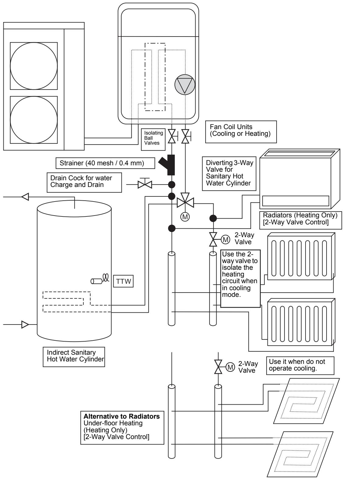
flowchart
graph TD
    A["Indirect Sanitary Hot Water Cylinder"] --> B["Drain Cock for water Charge and Drain"]
    B --> C["Strainer (40 mesh / 0.4 mm)"]
    C --> D["Isolating Ball Valves"]
    D --> E["Fan Coil Units (Cooling or Heating)"]
    E --> F["Diverting 3-Way Valve for Sanitary Hot Water Cylinder"]
    F --> G["Radiators (Heating Only) [2-Way Valve Control"]]
    G --> H["Use the 2-way valve to isolate the heating circuit when in cooling mode."]
    H --> I["2-Way Valve"]
    I --> J["Alternative to Radiators Under-floor Heating (Heating Only) [2-Way Valve Control"]]
    J --> K["Use it when do not operate cooling"]
■ Example of 2-Zone Temperature Control and Hot Water Supply System
The following shows an example of the 2-zone temperature control.
A buffer tank and a water pump are required for the 2-zone temperature control.
▼ Fig. 5-02
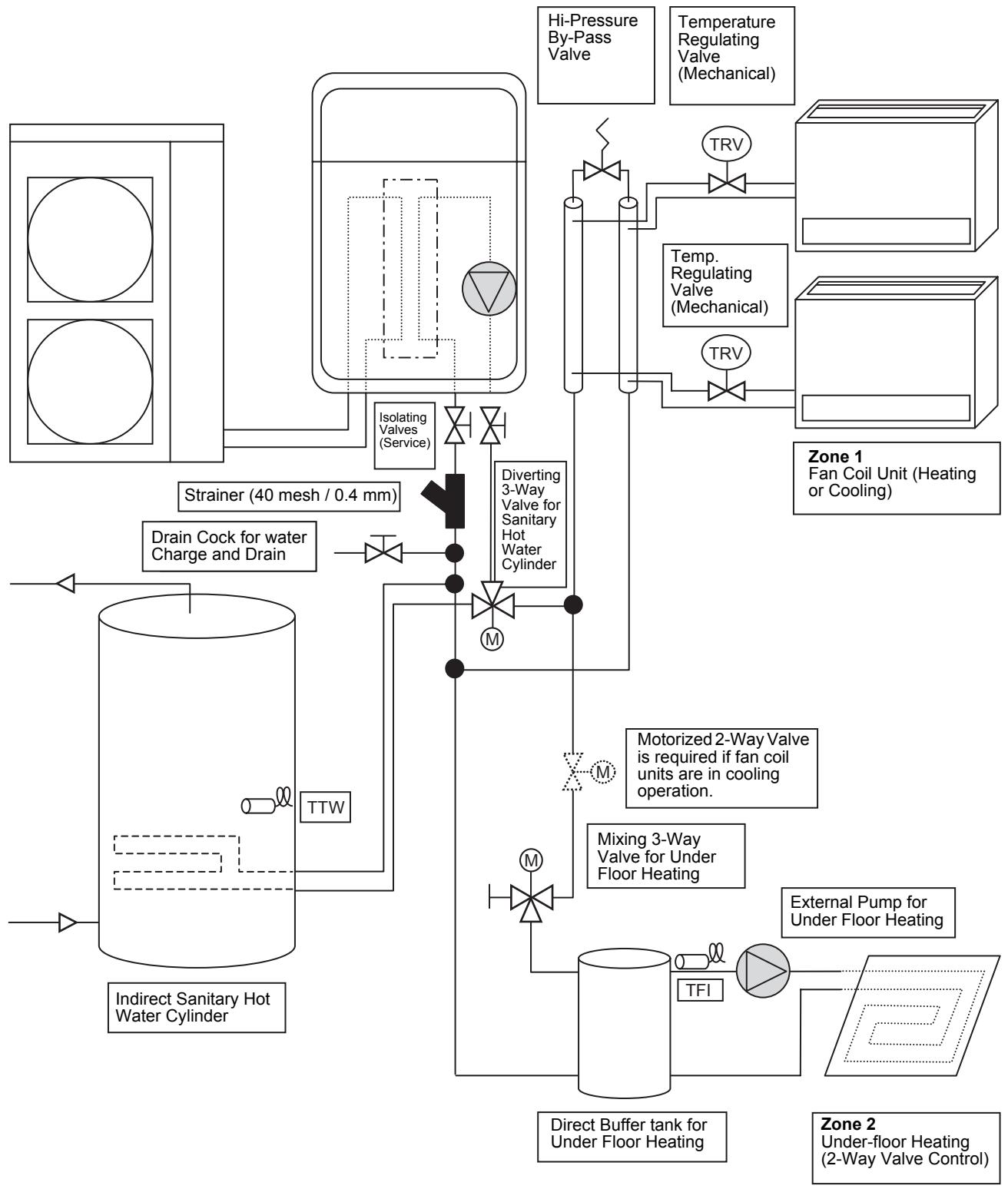
flowchart
graph TD
    A["Indirect Sanitary Hot Water Cylinder"] --> B["TTW"]
    B --> C["Isolating Valves (Service)"]
    C --> D["Diverting 3-Way Valve for Sanitary Hot Water Cylinder"]
    D --> E["Multi-Valve / Motorized 2-Way Valve"]
    E --> F["Mixing 3-Way Valve for Under Floor Heating"]
    F --> G["Direct Buffer tank for Under Floor Heating"]
    G --> H["TFI"]
    H --> I["External Pump for Under Floor Heating"]
    I --> J["Zone 2 Under-floor Heating (2-Way Valve Control)"]
    K["Strainer (40 mesh / 0.4 mm)"] --> L["Drain Cock for water Charge and Drain"]
    M["Hi-Pressure By-Pass Valve"] --> N["TRV"]
    O["Temperature Regulating Valve (Mechanical)"] --> P["TRV"]
    Q["Temp. Regulating Valve (Mechanical)"] --> R["TRV"]
    S["Zone 1 Fan Coil Unit (Heating or Cooling)"] --> T["TRV"]
    U["Motorized 2-Way Valve is required if fan coil units are in cooling operation."] --> V["Mixing 3-Way Valve for Under Floor Heating"]
    W["Indirect Sanitary Hot Water Cylinder"] --> X["TTW"]
6 MAIN COMPONENTS OF HYDRO UNIT
■ Exploded view and description for Hydro Unit
▼ Fig. 6-01
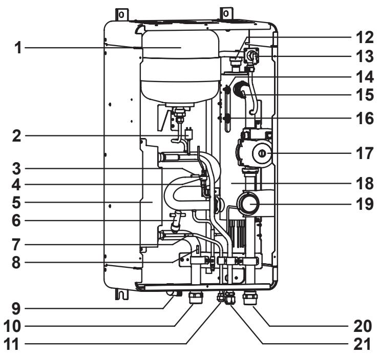
1 : Expansion vessel
2 : Pressure switch (4.15 MPa)
3 : Temperature sensor (for Heat pump outlet -TWO)
4 : Pressure sensor
5 : Heat exchanger
6 : Flow switch (13.0 L/min (8kw), 17.5 L/min (14kw))
7 : Temperature sensor (for refrigerant -TC)
8 : Temperature sensor (for water inlet -TWI)
9 : Drain nipple
10 : Water inlet connection
11 : Refrigerant liquid connection
12 : Air relief valve
13 : Pressure relief valve (0.3 MPa (3 bar))
14 : Thermal protector (auto)
15 : Temperature sensor (for water outlet THO)
16 : Thermal protector (Single operation)
17 : Water pump
18 : Backup heater (3 kW, 3 kW x 2, 3 kW x 3)
19 : Manometer
20 : Water outlet connection
21 : Refrigerant gas connection
■ E-Box layout
▼ Fig. 6-02
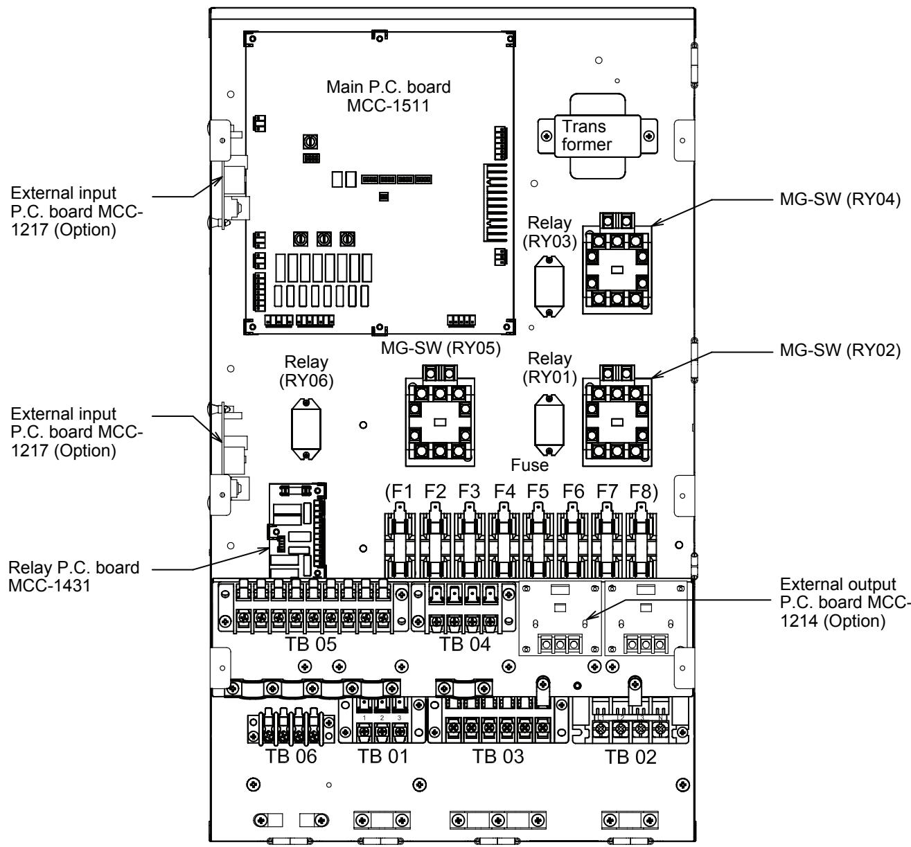
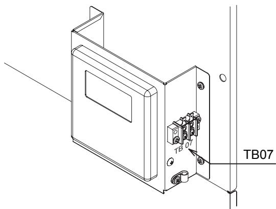
- To protect yourself from injury, always use PPE (Personal Protective Equipment), that is, wear gloves.
• Install the Hydro Unit by at least two persons. - Install the Hydro Unit in a place strong enough to withstand the following weights:
Hydro Unit weight with no water 60 kg (802) 65 kg (1402)
Hydro Unit weight with full water 80 kg (802) 85 kg (1402)

CAUTION
- Do not install the unit in a place where water freezes.
- Do not install the Hydro Unit in a place where combustible gas may leak.
- Do not install the Hydro Unit in a place exposed to rain or water.
- Do not install the Hydro Unit near equipment which generates heat.
- Do not install the Hydro Unit to a movable object.
- Do not install the Hydro Unit in a place exposed to vibration.
■ Handling, Unpacking, and Checking the Hydro Unit
- The unit should be checked when it is delivered, and any damage reported immediately to the courier claims the department.
■ Positioning
Service space
Secure a service space for the Hydro Unit.
- Do not install the Hydro Unit in a place where heat stagnates.
▼ Fig. 7-01
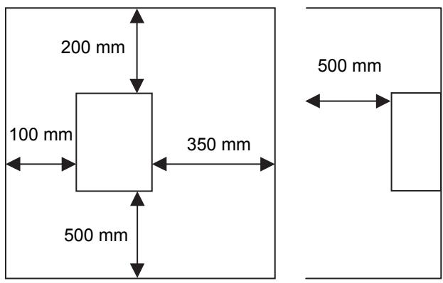
Mounting
Install M10 bolts at the positions shown below and secure them with nuts.
▼ Fig. 7-02
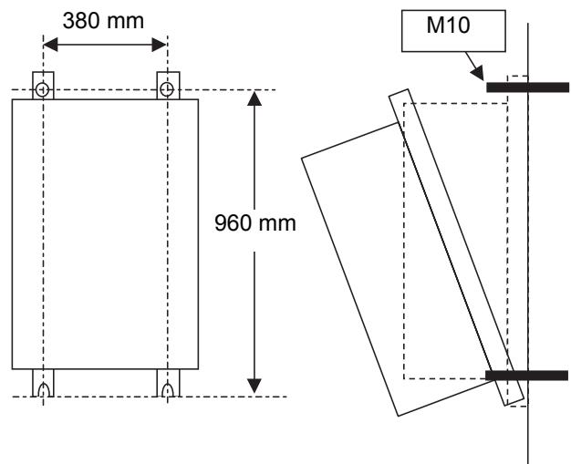
The Hydro Unit can be installed directly without using the fixing angles.
However, the back side of the Hydro Unit can be highly heated, therefore, the installing surface must be heat-resistant.
▼ Fig. 7-03
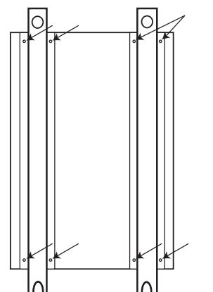
natural_image
Pure electrical circuit lines without any symbolsRemove the M5a screws to detach the fixing angles.
▼ Fig. 7-04
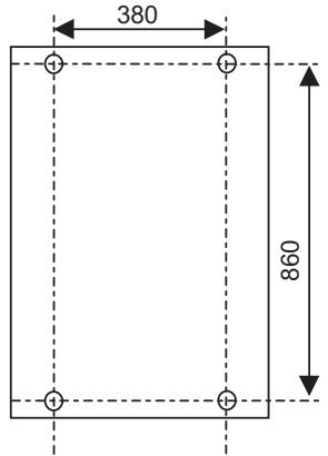
▼ Fig. 7-05
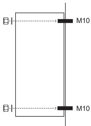
Secure the Hydro Unit with plain washers and nuts.
Install the Hydro Unit so that its tilting angle falls within the range below.
▼ Fig. 7-06
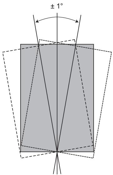
▼ Fig. 7-07
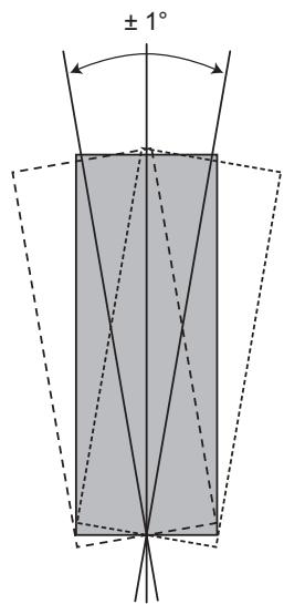
■ Refrigerant Piping

WARNING
- THIS SYSTEM ADOPTS HFC REFRIGERANT (R410A) WHICH DOES NOT DESTROY THE OZONE LAYER.
- The characteristics of R410A refrigerant are: ease to absorb water, oxidizing membrane or oil, and its pressure is approximately 1.6 times higher that of R22. Accompanied with the new refrigerant the oil has also been changed. Therefore during installation work prevention of the invasion of water, dust, former refrigerant or oil is of a paramount importance.
To prevent the charging of incorrect refrigerants into the system the service valve connection ports have also increased in size. - The use of R410A tools is required for correct installation of the system.
- The use of the correct pipe sizes and wall thicknesses of copper pipe work is required for the correct installation of the system.

CAUTION
- Ensure all refrigerant pipes are protected from the invasion of dust and water.
- Ensure all pipe work connections are tightened to the required torque settings detailed in this section.
- Perform an air tight using Oxygen Free Nitrogen (OFN) only.
- Evacuate the air in the pipe work using a vacuum pump.
- Check for refrigerant gas leaks at all connections throughout the pipe work.
NOTE
The Air to Water Heat Pump system uses R410A refrigerant. It is important that copper pipes used for refrigerant piping have the following wall thickness:
- 0.8 mm for ∅6.4 mm, ∅9.5 mm and ∅12.7 mm
• 1.0 mm for ∅15.9 mm
Refrigeration pipe
The length and height of the refrigeration pipe must be within the following values.
As long as the Hydro Unit is installed within these ranges, no additional refrigerant is required.
▼ Fig. 7-08
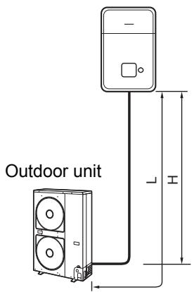
H: Max. ±30 m (above or below)
L: Max. 30 m
Min. 5 m
Refrigerant pipe sizes
| Hydro Unit Model | Gas Side (mm) | Liquid Side (mm) |
| 8 kW Hydro Unit | 15.88 | 9.52 |
| 14 kW Hydro Unit | 15.88 | 9.52 |
Flaring
- Cut the refrigerant pipes to the correct length using a pipe cutter. Remove any burrs that may be on the pipes as these may cause refrigerant leaks or component failure in the refrigeration cycle.
- Place the correct size flare nuts onto the pipes (use the flare nuts supplied with the Hydro Unit or use flare nuts designed specifically for R410A refrigerant) and then flare the pipes using the correct flaring tool.
Tightening
- Connect the refrigerant pipes, from the outdoor unit, to the Hydro Unit as shown below.
▼ Fig. 7-09
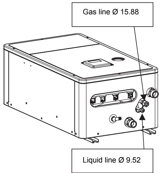
- Align the flare connection on each pipe with the corresponding outlet connection on the Hydro Unit. Tighten the flare nuts, using fingers, to secure the pipes in place.
- Tighten the flare nuts, using a torque wrench, to the tightening torques shown below:
| Outer ∅ of Copper Pipe (mm) | Tightening Torque (N/m) |
| 9.5 | 33 to 42 |
| 15.9 | 63 to 77 |
- To prevent damage, to the refrigerant pipes, use two spanners to tighten the flare nut connections to the required torque.
■ Water Pipe

WARNING
• Install water pipes according to the regulations of respective countries.
• Install water pipes in a freeze-free place.
- Make sure that water pipes have sufficient pressure resistance.
The setting value of the pressure relief valve is 0.3 MPa.

CAUTION
- Do not use zinc plated water pipes. When steel pipes are used, insulate both ends of the pipes.
- The water to be used must meet the water quality standard specified in EN directive 98/83 EC.
Water pipe
Design the water pipe length within the QH characteristics of the pump (Refer to "Fig. 7-16" and "Fig. 7-17" on page 101).
The height of the pipe must be 7 m or less.
▼ Fig.7-10
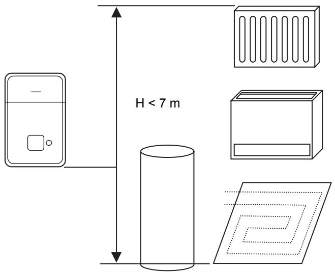
Water circuit
- Install a strainer with 30 to 40 meshes (locally procured) at the water inlet of the Hydro Unit.
• Install drain cocks (locally procured) for water charge and discharge at the lower part of the Hydro Unit. - Make the piping route a closed circuit. (An open water circuit may cause a failure.)
▼ Fig. 7-11
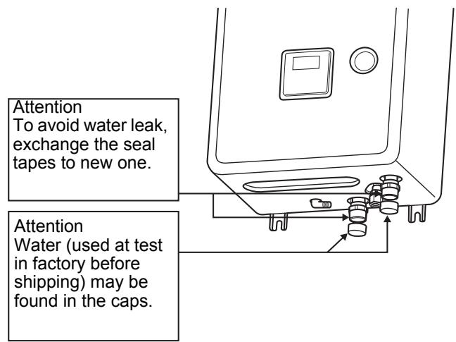
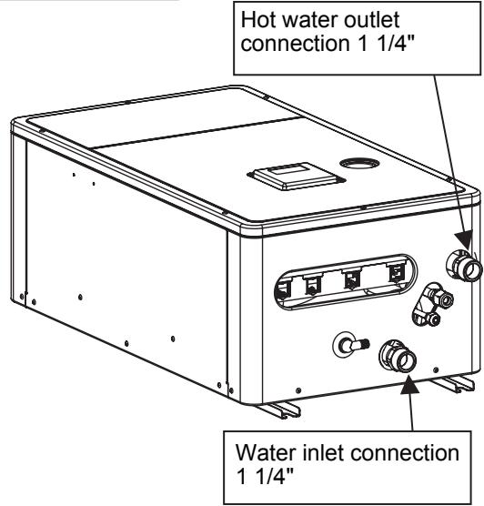
▼ Fig. 7-12
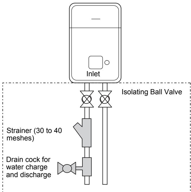
flowchart
graph TD
    A["Inlet"] --> B["Isolating Ball Valve"]
    B --> C["Strainer (30 to 40 meshes)"]
    B --> D["Drain cock for water charge and discharge"]
Local arrangement
Piping to hot water cylinder (option)
Water supplied to the hot water cylinder is branched by a motorized 3-way valve (locally procured).
For the specifications of the motorized 3-way valve, refer to "Control parts specifications" on page 105.
Connect the hot water cylinder to port A (open when energized) of the valve.
▼ Fig. 7-13
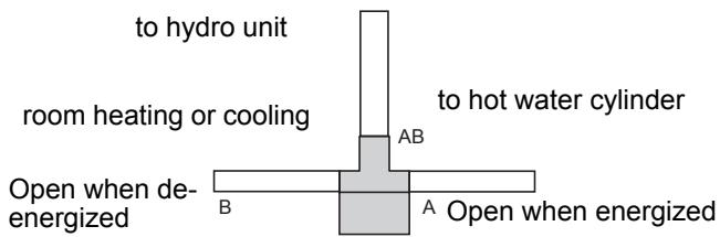
Piping to 2-zone operation
To perform 2-zone temperature control, circulate water by another pump (locally procured) through a motorized mixing valve (locally procured) and a buffer tank (locally procured).
For the specifications of the motorized mixing valve, Refer to "Control parts specifications" on page 105.
▼ Fig. 7-14

flowchart
graph LR
    A["Water pump (locally procured)"] --> B["Buffer tank (locally procured)"]
    B --> C["Motorized mixing valve (locally procured)"]
    C --> D["from hydro unit"]
    B --> E["Water pump (locally procured)"]
    style A fill:#f9f,stroke:#333
    style B fill:#ccf,stroke:#333
    style C fill:#cfc,stroke:#333
    style D fill:#fcc,stroke:#333
    style E fill:#cff,stroke:#333
Checking water volume and initial pressure of expansion vessel
The expansion vessel of the Hydro Unit has a capacity of 12 liters.
The initial pressure of the expansion vessel is 0.1 MPa (1 bar).
The pressure of the safety valve is 0.3 MPa (3 bar).
Verify whether the capacity of the expansion vessel is sufficient using the following expression. If the volume is insufficient, add the capacity locally.
Expression for expansion vessel selection
$$ V = \frac {\varepsilon \times V _ {S}}{1 - \frac {P _ {1}}{P _ {2}}} $$
V: Necessary total tank capacity ( )
ε: Water expansion coefficient at average hot water temperature
Vs: Total water amount in the system
P1: System pressure at tank setting position (MPaabs.) (Pipe inner pressure during pump operation before heating device operates = water supply pressure)
P2: Maximum pressure used during operation at tank setting position (MPaabs.) (= safety valve setting pressure)
* The absolute pressure value (abs.) is obtained by adding the atmospheric pressure (0.1 MPa (1 bar)) to the gauge pressure.
▼ Tank selection method
| Water temperature and expansion coefficient | |||
| Hot water temperature (°C) | Expansion rate | Hot water temperature (°C) | Expansion rate |
| 0 | 0.0002 | 50 | 0.0121 |
| 4 | 0.0000 | 55 | 0.0145 |
| 5 | 0.0000 | 60 | 0.0171 |
| 10 | 0.0003 | 65 | 0.0198 |
| 15 | 0.0008 | 70 | 0.0229 |
| 20 | 0.0017 | 75 | 0.0258 |
| 25 | 0.0029 | 80 | 0.0292 |
| 30 | 0.0043 | 85 | 0.0324 |
| 35 | 0.0050 | 90 | 0.0961 |
| 40 | 0.0078 | 95 | 0.0967 |
| 45 | 0.0100 | ||
▼ Fig. 7-15
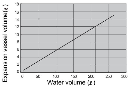
line
| Water volume (ℓ) | Expansion vessel volume(ℓ) | | ---------------- | -------------------------- | | 0 | 0 | | 50 | 2 | | 100 | 4 | | 150 | 6 | | 200 | 8 | | 250 | 10 | | 300 | 12 | | 350 | 14 | | 400 | 16 | | 450 | 18 |*Hot water temperature 55°C
Install an external expansion vessel when the capacity of the expansion vessel is insufficient.
Pump operation/configuration
▼ Fig. 7-16
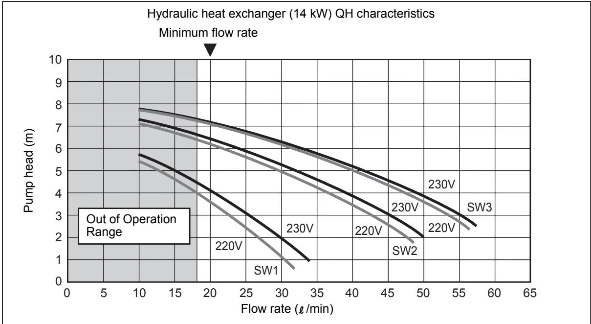
line
| Flow rate (l/min) | Pump head (m) | Voltage (V) | | ----------------- | ------------- | ----------- | | 10 | 7.5 | 220 | | 10 | 7.8 | 230 | | 10 | 7.6 | SW3 | | 10 | 7.4 | SW2 | | 10 | 7.2 | SW1 | | 25 | 6.5 | 220 | | 25 | 6.8 | 230 | | 25 | 6.6 | SW3 | | 25 | 6.4 | SW2 | | 25 | 6.2 | SW1 | | 30 | 5.5 | 220 | | 30 | 5.8 | 230 | | 30 | 5.6 | SW3 | | 30 | 5.4 | SW2 | | 30 | 5.2 | SW1 | | 35 | 4.5 | 220 | | 35 | 4.8 | 230 | | 35 | 4.6 | SW3 | | 35 | 4.4 | SW2 | | 35 | 4.2 | SW1 | | 40 | 3.5 | 220 | | 40 | 3.8 | 230 | | 40 | 3.6 | SW3 | | 40 | 3.4 | SW2 | | 40 | 3.2 | SW1 | | 45 | 2.5 | 220 | | 45 | 2.8 | 230 | | 45 | 2.6 | SW3 | | 45 | 2.4 | SW2 | | 45 | 2.2 | SW1 | | 50 | 1.5 | 220 | | 50 | 1.8 | 230 | | 50 | 1.6 | SW3 | | 50 | 1.4 | SW2 | | 50 | 1.2 | SW1 | | 55 | 0.5 | 220 | | 55 | 0.8 | 230 | | 55 | 0.6 | SW3 | | 55 | 0.4 | SW2 | | 55 | 0.2 | SW1 | | 60 | - | - | | - | - | - | | - | - | - | | - | - | - | | - | - | - | | - | - | - | | - | - | - | | - | - | - | | - | - | - | | - | - | - | | - | - | - | | - | - | - | | - | - | - | | - | - | - | | - | - | - | | - | - | - | | - | - | - | | - | - | - | | - | - | - | | - | - | - | | - | - | - | | - | - | - | | - | - | - | | - | - | - | | - | - | - | | - | - | - | | - | - | - | | - | - | - | | - | - | - | | - | - | - | | - | - | - | | - | - | - | | - | - | - | | - | - | - | | - | - | - | | - | - | - | | - | - | - | | - | - | - | | - | - | - | | - | - | - | | - | - | - | | - | - | - | | - | - | - | | - | - | - | | - | - | - | | - | - | - | | - | - | - | | - | - | - | | - | - | - | | - | - | - | | - | - | - | | - | - | - | | - | - | - | | - | - | - | | - | - | - | | - | - | - | | - | - | - | | - (out of Operation Range)▼ Fig. 7-17
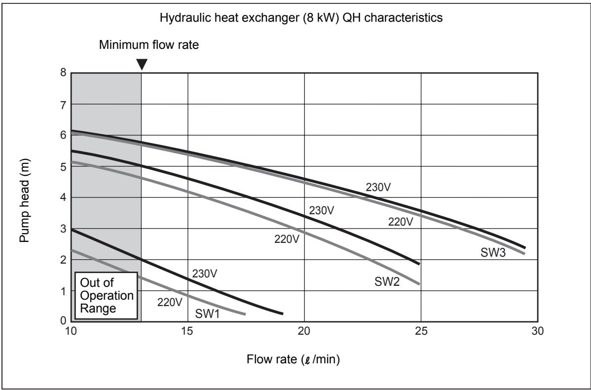
line
| Flow rate (l/min) | Pump head (m) for 220V | Pump head (m) for 230V | Pump head (m) for 230V | Pump head (m) for 220V | Pump head (m) for SW1 | Pump head (m) for SW2 | Pump head (m) for SW3 | | ----------------- | ---------------------- | ---------------------- | ---------------------- | ---------------------- | --------------------- | --------------------- | --------------------- | | 10 | 6.0 | 5.5 | 5.0 | 4.5 | 3.0 | 2.5 | 2.0 | | 15 | 5.0 | 4.5 | 4.0 | 3.5 | 1.5 | 1.0 | 0.5 | | 20 | 4.0 | 3.5 | 3.0 | 2.5 | 0.5 | 0.2 | 0.1 | | 25 | 3.0 | 2.5 | 2.0 | 1.5 | 0.1 | 0.05 | 0.02 | | 30 | 2.0 | 1.5 | 1.0 | 0.5 | 0.05 | 0.01 | 0.005 |Water charging
Charge water until the pressure gauge shows 0.2 MPa (2 bar).
Hydraulic pressure may drop when the trial run begins. In that case, add water.
Air may enter if the charged hydraulic pressure is low.
Loosen the purge valve cap by two turns to release air.
▼ Fig. 7-18
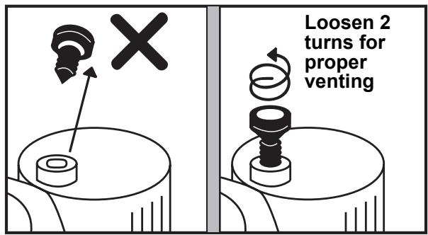
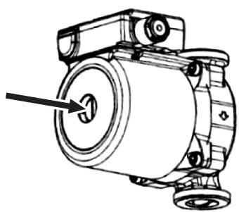
natural_image
Technical line drawing of an electric motor with a knob inserted (no text or symbols)Loosen the air vent screw of the pump, pull out air in the pump, and tighten again.
Loosen the cap of the pressure relief valve to release air.
Water may come out of the pressure relief valve.
Release the air completely from the water circuit.
Failure to do so may disable correct operation.
Water quality
The water used must satisfy EN directive 98/83 EC.
Piping insulation
It is recommended that insulation treatment be applied to all pipes. To perform optional cooling operation, apply insulation treatment of 20 t or more to all pipes.
■ Electrical Installation

WARNING
- Ensure electrical circuits are isolated before commencing the electrical installation.
- The electrical installation must be completed by a qualified electrician.
- The electrical installation must comply to all Local, National and International electrical installation regulations.
- This product must be earthed in accordance with Local, National and International electrical installation regulations.

CAUTION
- The Hydro Unit must be connected to a dedicated power supply for the back up heater circuit.
- The electrical supply must be protected by a suitably sized over current protection device (fuse, MCB etc) and an earth leakage protection device.
- The Hydro Unit must be connected to the mains power supply using a isolating switch which disconnects all poles and has a contact separation of at least 3 mm.
- The cord clamps, attached to the Hydro Unit, must be used to secure the electrical cables.
- Wrong connection of electrical cables may result in electrical component failure or fire.
- Ensure the electrical cables are sized in accordance with the installation instructions.
Control line
▼ Fig. 7-19

flowchart
graph TD
    A["Pump (local)"] --> B["Booster heater (local)"]
    B --> C["3Way-Valve for hot water cylinder"]
    C --> D["2Way-Valve for cooling stop"]
    D --> E["Max 12 m 230 V 100 mA 0.75 mm² or more"]
    E --> F["Max 12 m 230 V 1 A 0.75 mm² or more"]
    F --> G["TB04"]
    G --> H["Mixing-Valve type 2 for 2 zone control"]
    H --> I["Max 12 m 230 V 100 mA 0.75 mm² or more"]
    I --> J["Max 5 m shielded wire 0.75 mm² or more"]
    J --> K["TB06"]
    K --> L["A"]
    K --> M["B"]
    K --> N["C"]
    K --> O["D"]
    K --> P["Temp sensor in hot water cylinder"]
    P --> Q["Max 5 m shielded wire 0.75 mm² or more"]
    Q --> R["TB07"]
    R --> S["A"]
    R --> T["B"]
    R --> U["C"]
    R --> V["D"]
    R --> W["Temp sensor for 2 zone control"]
    W --> X["Max 50 m shielded wire 0.75 mm² or more"]
    X --> Y["TB09"]
    Y --> Z["A"]
    Y --> AA["B"]
    Y --> AB["C"]
    Y --> AC["D"]
    Y --> AD["Temp sensor in hot water cylinder"]
    AD --> AE["Max 12 m non voltage 0.75 mm² or more"]
    AE --> AF["TB05"]
    AF --> AG["CN208 OPTION PJ20"]
    AF --> AH["CN209 OPTION PJ20"]
    AG --> AI["Alert output (local)"]
    AH --> AJ["Boiler operation (local)"]
    AH --> AK["Defrost output (local)"]
    AH --> AL["Compressor operation output (local)"]
    AI --> AM["2nd Remote control"]
    AJ --> AN["2nd Remote control"]
    AK --> AO["2nd Remote control"]
▼ Fig. 7-20
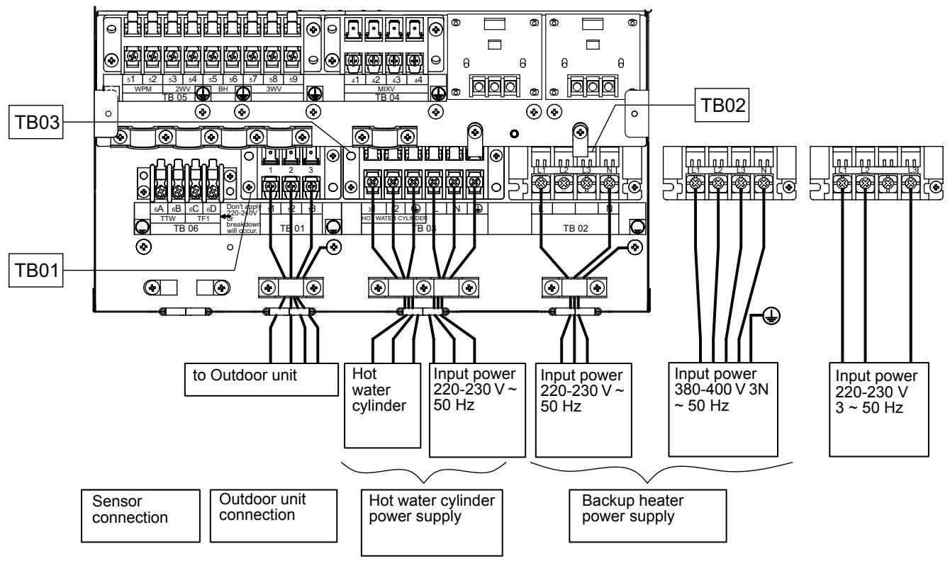
Electrical supply/cable specifications
▼ Wiring specifications
| Description | Model name HWS- | POWER SUPPLY | Maximum current | Installation fuse rating | Power wire | Connection destination | ||
| Outdoor unit power | Power input | 1403H-E | 220-230 V ~ 50 Hz | 22.8A | 25 A | 2.5 mm^2 or more | L, N | |
| 1103H-E | 220-230 V ~ 50 Hz | 22.8A | 25 A | 2.5 mm^2 or more | ||||
| 803H-E | 220-230 V ~ 50 Hz | 19.2A | 20A | 2.5 mm^2 or more | ||||
| 1603H8-E, 1603H8R-E | 380-400V 3N~ 50Hz | 14.6A | 16A | 2.5 mm^2 or more | L1, L2, L3, N | |||
| 1403H8-E, 1403H8R-E | 380-400V 3N~ 50Hz | 14.6A | 16A | 2.5 mm^2 or more | ||||
| 1103H8-E, 1103H8R-E | 380-400V 3N~ 50Hz | 14.6A | 16A | 2.5 mm^2 or more | ||||
| Hydro inlet heater power | Power input for backup heater | 1403XWHM3-E | 220-230V ~ 50Hz | 13A | 16A | 1.5 mm^2 or more | L, N | TB02 |
| 1403XWHD6-E | 220-230V 3~ 50Hz | 23A | 25A | 2.5 mm^2 or more | L1, L2, L3 | |||
| 1403XWHT6-E | 380-400V 3N~ 50Hz | 13A(13A x 2P) | 16A | 1.5 mm^2 or more | L1, L2, L3, N | |||
| 1403XWHT9-E | 380-400V 3N~ 50Hz | 13A(13A x 3P) | 16A | 1.5 mm^2 or more | ||||
| 803XWHM3-E | 220-230V ~ 50Hz | 13A | 16A | 1.5 mm^2 or more | L, N | |||
| 803XWHD6-E | 220-230V 3~ 50Hz | 23A | 25A | 2.5 mm^2 or more | L1, L2, L3 | |||
| 803XWHT6-E | 380-400V 3N~ 50Hz | 13A(13A x 2P) | 16A | 1.5 mm^2 or more | L1, L2, L3, N | |||
| 803XWHT9-E | 380-400V 3N~ 50Hz | 13A(13A x 3P) | 16A | 1.5 mm^2 or more | ||||
| Power input for cylinder heater | 220-230V ~ 50Hz | 12A | 16A | 1.5 mm^2 or more | L, N | TB03 | ||
| Outdoor-Hydro unit | Connection | 1.5 mm^2 or more | 1, 2, 3 | |||||
| Hydro -Cylinder | Connection | 1.5 mm^2 or more | 1, 2 | TB03 | ||||
▼ Wiring specifications (control line)
| Description | Line spec | Maximum current | Maximum length | Connection destination | |
| 3-way valve control | 2 line or 3 line | 100 mA | 12 m | 0.75 mm^2 or more | 7,8,9(TB05) |
| 2-way valve control | 2 line | 100 mA | 12 m | 0.75 mm^2 or more | 3,4(TB05) |
| Mixing valve control | 3 line | 100 mA | 12 m | 0.75 mm^2 or more | 1,2,3or2,3,4(TB04) |
| 2-zone thermo sensor | 2 line | 100 mA | 5 m | 0.75 mm^2 or more | C, D(TB06) |
| Cylinder thermo sensor | 2+GND(shielded wire) | 100 mA | 5 m | 0.75 mm^2 or more | A, B(TB06) |
| Second remote controller | 2 line | 50 mA | 50 m | 0.5 mm^2 or more | 1,2(TB07) |
▼ Control parts specifications
| Power | Maximum current | Type | |
| Motorized 3-way valve (for hot water) | AC 230 V | 100 mA | Default: 2-wire spring return valve or 3 wire SPST valveNote: 3 wire SPDT valve can be used by changing DIP switch 13_1. |
| Motorized 2-way valve (for cooling) | AC 230 V | 100 mA | spring return type (normally open) |
| Motorized mixing valve (for 2-zone) | AC 230 V | 100 mA | Default: Drive time = 60sec to 90°Note: 3 wire SPST or SPDT valves, with drive times between 30 and 240 seconds, can be used. Valve drive time can be changed using function code 0C |
▼ Output line specifications
| Description | Output | Maximum current | Max voltage | Maximum length | |
| External pump No.1 | AC230V | 1 A | - | 12 m | |
| External boost heater | AC230V | 1 A | - | 12 m | Output as required when outdoor air temperature is -20°C or less |
| Boiler control | Non-voltage contacts | 0.5 A | AC230 V | 12 m | Output as required when outdoor air temperature is -10°C or less. The outdoor air temperature, when the boiler output is enabled, can be changed using function code 23. |
| 1 A | DC24 V | 12 m | |||
| ALARM Output | Non-voltage contacts | 0.5 A | AC230 V | 12 m | |
| 1 A | DC24 V | 12 m | |||
| Compressor operation output | Non-voltage contacts | 0.5 A | AC230 V | 12 m | |
| 1 A | DC24 V | 12 m | |||
| Defrost Output | Non-voltage contacts | 0.5 A | AC230 V | 12 m | |
| 1 A | DC24 V | 12 m |
▼ Input line specifications
| Description | Input | Maximum length |
| Emergency stop control | Non-voltage | 12 m |
| Cooling thermostat input | Non-voltage | 12 m |
| Heating thermostat input | Non-voltage | 12 m |

CAUTION
Earthing arrangements
The Hydro Unit and related equipment must be earthed in accordance with your local and national electrical regulations. It is essential that the equipment is earthed to prevent the electric shock and damage to the equipment.
Electrical connection to hydro unit
- Remove the front cover and the electrical box cover from the Hydro Unit.
- The Hydro Unit power cable must be sized in accordance with refer to “Electrical supply/cable specifications”.
- Connect the Hydro Unit power cable to Terminal 02 as shown below.
▼ Fig. 7-21
Backup heater
220-230V \~ type
(3kW type)
Backup heater
380-400V 3N\~
type
(6,9kW type)
Backup heater
220-230V 3\~
type
(6kW type)
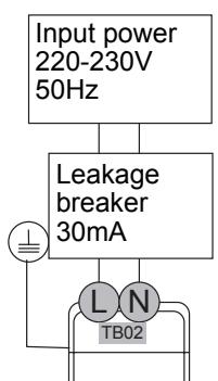
flowchart
graph TD
    A["Input power 220-230V 50Hz"] --> B["Leakage breaker 30mA"]
    B --> C["L N TB02"]
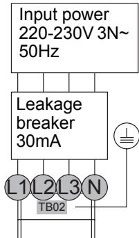
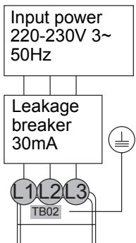
- Ensure the Hydro Unit power cable is secured using the cable clamp fitted in the electrical box.
- Ensure the Hydro Unit power cable connection terminals are tight.
Outdoor unit to hydro unit electrical connection
▼ Fig. 7-22
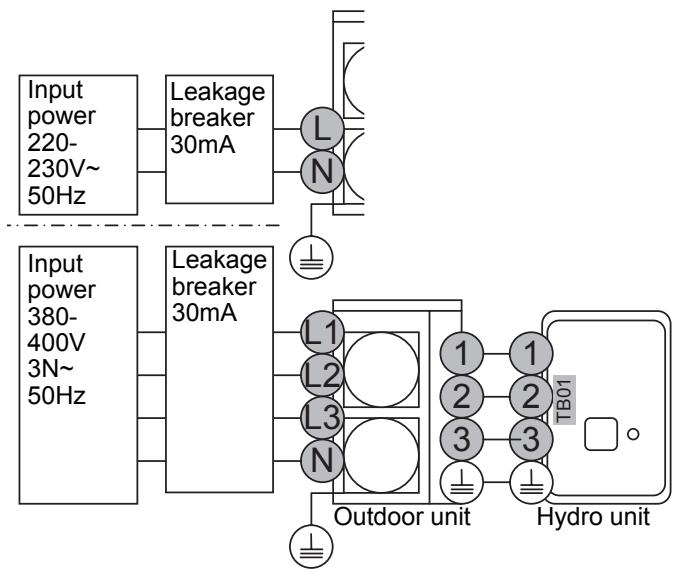
flowchart
graph TD
    A["Input power 220-230V~50Hz"] --> B["Leakage breaker 30mA"]
    C["Input power 380-400V 3N~50Hz"] --> D["Leakage breaker 30mA"]
    B --> E["L N"]
    D --> F["L1 L2 L3 N"]
    E --> G["Outdoor unit"]
    F --> G
    G --> H["TB01 Hydro unit"]
    style A fill:#f9f,stroke:#333
    style C fill:#f9f,stroke:#333
    style B fill:#ccf,stroke:#333
    style D fill:#ccf,stroke:#333
    style E fill:#cfc,stroke:#333
    style F fill:#cfc,stroke:#333
    style G fill:#fcc,stroke:#333
    style H fill:#fcc,stroke:#333
- Ensure electrical circuits are isolated before commencing work.
- The Outdoor Unit to Hydro Unit interconnecting cable must be sized in accordance with refer to "Electrical supply/cable specifications".
- Connect the Outdoor Unit to Hydro Unit interconnecting cable as shown in the diagram above.
- Ensure the Outdoor Unit to Hydro Unit interconnecting cable is secured using the cable clamp fitted in the electrical box.
- Ensure the Outdoor Unit to Hydro Unit interconnecting cable connection terminals are tight.
Electrical connection for external booster heater

CAUTION
- The maximum current available from the booster heater output is 1 A. Do not connect the booster heater directly to Terminal Block 05 on the Hydro Unit. A separate contactor, supplied locally, must be used to supply the booster heater.
- The booster heater can be installed only for room heating and cannot be used for hot water supply.
- Install the booster heater downstream of the 3-way valve on the indoor unit side. The booster heater is an external heater, supplied locally, used to assist the Hydro Unit during low ambient conditions.
- The AC230 V 1 A output from the Hydro Unit must only be used to energize an external contactor. (Supplied locally)
- The output from the Hydro Unit is only enabled when the outdoor air temperature is less than -20°C.
-
Ensure the external booster heater is installed and set up in accordance with all Local, National and International regulations.
-
Connect the external booster heater to the Hydro Unit in accordance with the diagram shown below.
- Connect the coil, of the field supplied contactor, to terminals 5 & 6 on Terminal Block 05. The contactor will energize in the event of low ambient conditions.
- A separate dedicated electrical supply must be used for the external booster heater. This must be connected through the contacts on the field supplied contactor.
▼ Fig. 7-23
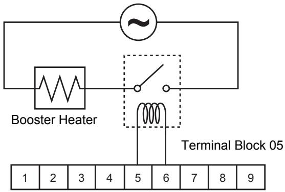
Electrical connection for external additional pumps
- The Hydro Unit has the facility to connect an additional circulating pump, if required, into the heating or cooling system.
- There is an output available from the Hydro Unit. AC230 V 1 A (maximum) is available from each output. The output for each additional pump is synchronized with the operation of the main circulating pump inside the Hydro Unit.
- Connect the additional pumps as shown in the diagram below.
- Connect external pump 1 to terminals 1 & 2 on Terminal Block 05.
- Install external pumps so that their motive power does not affect the internal pump.
▼ Fig. 7-24
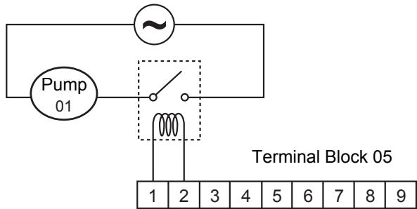
3-way valve (diverter) connection
Required Valve Specification:
Electrical Specification: 230 V; 50 Hz; <100 mA
Valve Diameters: Port A, Port B: ∅ 1 1/4"
Return Mechanism: 3 types of 3-way valve (diverter) can be used.
Set the 3-way valve in use with the DIP switch SW13-1 on the Hydro Unit board.
| SW13-1 | ||
| Type 1 | 2-wire spring return | OFF |
| Type 2 | 3-wire SPST | OFF |
| Type 3 | 3-wire SPDT | ON |
NOTE
Continuous operation of the valve motor at the fully open position is not recommended.
- The 3-way diverter valve is used to select either domestic hot water or space heating.
- Connect the 3-way diverter valve to terminals 7, 8 and 9 on Terminal Block 05.
- Connect the 3-way diverter valve in accordance with the diagram below:
▼ Fig. 7-25
Type 1: SPRING RETURN
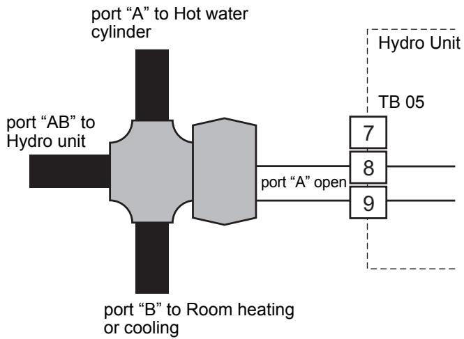
flowchart
graph TD
    A["port "A" to Hot water cylinder"] --> B["port "AB" to Hydro unit"]
    B --> C["port "B" to Room heating or cooling"]
    C --> D["port "A" open"]
    D --> E["7"]
    D --> F["8"]
    D --> G["9"]
    H["Hydro Unit"] --> I["TB 05"]
▼ Fig. 7-26
Type 2: SPST
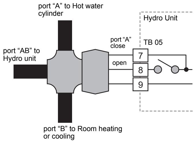
flowchart
graph LR
    A["port "AB" to Hot water cylinder"] --> B["port "A" close"]
    B --> C["7"]
    B --> D["8"]
    B --> E["9"]
    F["port "B" to Room heating or cooling"] --> G["open"]
    H["Hydro Unit"] --> I["TB 05"]
    I --> J["●"]
    I --> K["●"]
▼ Fig. 7-27
Type 3: SPDT
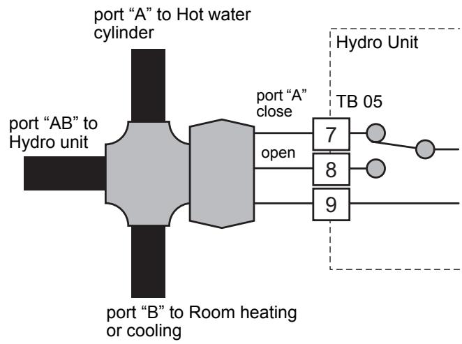
flowchart
graph TD
    A["port "AB" to Hot water cylinder"] --> B["port "A" close"]
    B --> C["7"]
    B --> D["8"]
    B --> E["9"]
    F["port "B" to Room heating or cooling"] --> G["open"]
    H["Hydro Unit"] --> I["TB 05"]
3-way mixing valve connection
Required Actuator Specification
Electrical Specification:230 V; 50 Hz; <100 mA The 3-way mixing valve is used to achieve the temperature differential needed in a 2-zone heating system.
- Connect the 3-way mixing valve to terminals 2, 3 and 4 on Terminal Block 04 (for Type 1 mixing valve) or on terminals 1, 2 and 3 on Terminal Block 04 (for Type 2 mixing valve).
- Connect the 3-way mixing valve in accordance with the diagrams below:
▼ Fig. 7-28
Type 1: SPDT
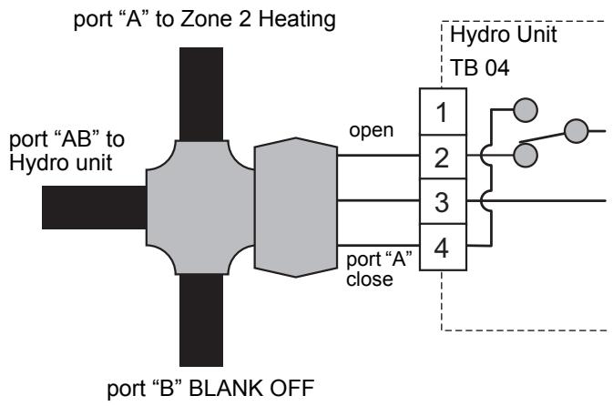
flowchart
graph LR
    A["port "A" to Zone 2 Heating"] --> B["port "AB" to Hydro unit"]
    B --> C["open"]
    C --> D["1"]
    C --> E["2"]
    C --> F["3"]
    C --> G["4"]
    H["port "B" BLANK OFF"] --> I["4"]
    J["Hydro Unit TB 04"] --> K["1"]
    J --> L["2"]
    J --> M["3"]
    J --> N["4"]
▼ Fig. 7-29
Type 2: SPST
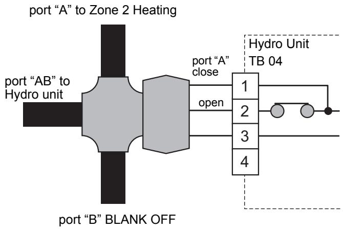
flowchart
graph LR
    A["port "A" to Zone 2 Heating"] --> B["port "AB" to Hydro unit"]
    B --> C["port "A" close"]
    C --> D["1"]
    C --> E["2"]
    C --> F["3"]
    C --> G["4"]
    D --> H["Hydro Unit TB 04"]
    E --> H
    F --> H
    G --> H
    H --> I["port "B" BLANK OFF"]
Hot water cylinder connection (optional)
- Please refer to "Electrical supply/cable specifications" for fuse/cable size and for connection details.
Electrical Connection (Hot Water Cylinder Electric Heater)
- The electric heater, incorporated in the hot water cylinder, requires a separate supply to Hydro Unit.
- Connect the hot water cylinder heater electrical supply in accordance with shown below:
Live conductor: Terminal L on Terminal Block 03 Neutral conductor: Terminal N on Terminal Block 03 Earth Conductor: Earth terminal on Terminal Block 03 - Connect the hot water cylinder heater to the Hydro Unit as shown below:
Live conductor to hot water cylinder: Terminal 1 on Terminal Block 03
Neutral conductor to hot water cylinder: Terminal 2 on Terminal Block 03
Earth conductor to hot water cylinder: Earth terminal on Terminal Block 03
▼ Fig. 7-30
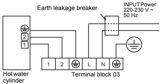
Electrical Connection (Hot Water Cylinder temperature Sensor)
- Connect the hot water cylinder temperature sensor as shown below to terminals A & B on Terminal Block 06 in the Hydro Unit.
- Please ensure that the interconnecting cable, between the Hydro Unit and the hot water cylinder, is connected to earth at both ends of the cable using the shield wire.
▼ Fig. 7-31
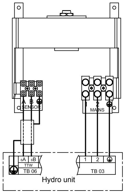
Additional hydro unit outputs
Alarm and Boiler Outputs
Alarm Output: L1: Alarm output
- Output enabled when the system is in alarm/fault condition.
- Volt free contact - specification shown below: AC230 V; 0.5 A (maximum) DC24 V; 1 A (maximum)
- Connection details: Terminals 1 and 2 (OPERATION) on MCC-1217 TB (Refer to "Fig. 7-32")
Boiler Control Output: L2: Boiler drive permission output
- Output enabled when outdoor ambient temperature < -10^ C
- Volt free contact - specification shown below: AC230 V; 0.5 A (maximum) DC24 V; 1 A (maximum)
- Connection details: Terminals 3 and 4 (EMG) on MCC-1217 TB (Refer to "Fig. 7-32")
▼ Fig. 7-32
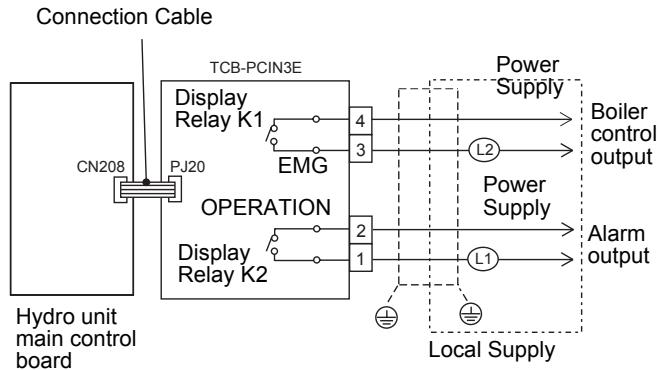
flowchart
graph TD
    A["Connection Cable"] --> B["CN208"]
    B --> C["PJ20"]
    C --> D["Display Relay K1"]
    D --> E["4"]
    D --> F["3"]
    G["Hydro unit main control board"] --> H["Display Relay K2"]
    H --> I["2"]
    H --> J["1"]
    K["POWER Supply"] --> L["Boiler control output"]
    M["Power Supply"] --> N["Alarm output"]
    O["Local Supply"] --> P["Local Supply"]
    style A fill:#f9f,stroke:#333
    style G fill:#f9f,stroke:#333
    style K fill:#f9f,stroke:#333
    style O fill:#f9f,stroke:#333
Defrost and Compressor operation Outputs Defrost output
- Display relay is ON when the system defrost.
- Volt free contact AC230 V; 0.5 A (maximum) DC24 V; 1 A (maximum)
- Connection details: Terminals 1 and 2 (OPERATION) on MCC-1217 TB (Refer to "Fig. 7-33")
Compressor operation output
- Display relay is ON with outdoor unit compressor operation.
- Volt free contact AC230 V; 0.5 A (maximum) DC24 V; 1 A (maximum)
- Connection details: Terminals 3 and 4 (EMG) on MCC-1217 TB (Refer to "Fig. 7-33")
▼ Fig. 7-33
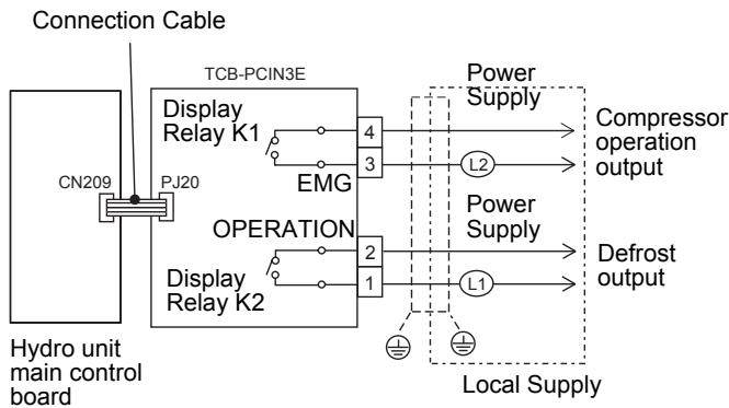
flowchart
graph TD
    A["Connection Cable"] --> B["CN209"]
    B --> C["PCN3E TCB-PCIN3E"]
    C --> D["Display Relay K1 EMG"]
    C --> E["Display Relay K2 OPERATION"]
    D --> F["4"]
    D --> G["3"]
    E --> H["2"]
    E --> I["1"]
    F --> J["Power Supply L2"]
    G --> K["Power Supply L1"]
    H --> L["Local Supply"]
    I --> L
    J --> M["Compressor operation output"]
    K --> N["Defrost output"]
    style A fill:#f9f,stroke:#333
    style B fill:#ccf,stroke:#333
    style C fill:#cfc,stroke:#333
    style D fill:#fcc,stroke:#333
    style E fill:#cff,stroke:#333
    style F fill:#ffc,stroke:#333
    style G fill:#ffc,stroke:#333
    style H fill:#ffc,stroke:#333
    style I fill:#ffc,stroke:#333
    style J fill:#fff,stroke:#333
    style K fill:#fff,stroke:#333
    style L fill:#fff,stroke:#333

CAUTION
- Be sure to prepare a non-voltage contact for each terminal.
- Display Relay capacity of "EMG" and "OPERATION". Below AC230 V 0.5 A (COS ∅ = 100 %)
When connecting loads such as relay coil to "L1, L2" load, insert noise surge absorber.
Below DC24 V 1 A (Non-inductive load)
When connecting load such as relay coil to "L1, L2" load, insert the bypass circuit.
Optional inputs to hydro unit
Room Thermostat Input:
2–3: Room thermostat input for cooling mode
1–3: Room thermostat input for heating mode
- Output enabled when either heating or cooling mode selected on room thermostat. (locally supplied)
- Volt free contacts
- Connection details:
Cooling Connection: Terminals 3 (COM) and 2 (COOL) on TCB-PCMO3E (Refer to "Fig. 7-34")
Heating Connection: Terminals 3 (COM) and 1 (HEAT) on TCB-PCMO3E (Refer to "Fig. 7-34")
▼ Fig. 7-34
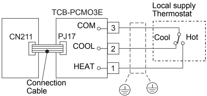
Thermostat operation
| Cooling | Heating | |||
| on | off | on | off | |
| 2 - 3 | open | close | - | - |
| 1 - 3 | - | - | close | open |

CAUTION
- Be sure to prepare a non-voltage continuous contact for each terminal.
- Supplementary Insulation must be added to user touchable part of switches.
Emergency Shutdown input
S2: Emergency stop input, Tempo* control input This function can be switched over with FC21 and FC61.
• Non-voltage contacts
- Connection details:
Emergency stop, Tempo* control ON: Terminals 3 (COM) and 1 (HEAT) on TCB-PCMO3E (Refer to "Fig. 7-35")
* a price contract provided by French electric power company EDF
▼ Fig. 7-35
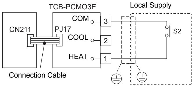
flowchart
graph TD
    A["CN211"] --> B["Connection Cable"]
    B --> C["TCB-PCMO3E"]
    C --> D["COM"]
    C --> E["COOL"]
    C --> F["HEAT"]
    D --> G["Local Supply"]
    E --> G
    F --> G
    G --> H["S2"]

CAUTION
- Be sure to prepare a non-voltage continuous contact for each terminal.
- Supplementary Insulation must be added to user touchable part of switches.
Electrical safety checks
The electrical safety checks must be completed before turning on the electrical supplies to the Air to Water heat pump system. The electrical safety checks should be completed by a qualified electrician. All results measured should comply with your local/national electrical installation regulations.
Earth continuity test
On completion of the electrical installation a resistance test should be completed on the earth conductor to ensure continuity between all pieces of equipment on the earth conductor.
Insulation resistance test
This test must be completed using a 500 V D.C. insulation resistance tester. Insulation resistance tests should be completed between each live terminal and earth.
■ Second remote controller
Installation place
- Install the remote controller 1 m - 1.5 m above floor level (average room temperature area).
- Do not install the remote controller in a place exposed to direct sunlight or outside air (such as a window, etc.).
- Do not install the remote controller where ventilation is poor.
- Do not install the remote controller in a freezing or refrigerated area - the remote controller is not water or splash-proof.
• Install the remote controller in a vertical position.
Remote controller installation dimension
Be sure to follow the installation dimension as shown in the figure 1 when you install the remote controller on the wall.
(mm)
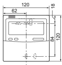
Remote controller installation
NOTE
- The remote controller wire should not be bundled with other wires (mains, etc.), or installed with other wires in the same conduit, as malfunction may result.
• Install the remote controller away from sources of electrical interference and electromagnetic fields. - If electrical interference is unavoidable, countermeasures such as appropriate filtering should be employed.
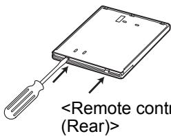
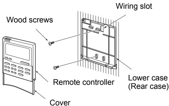
- For removal of the remote controller's lower case (rear case), insert the tip of a straight blade screwdriver, or the like, into the two openings at the bottom of the remote controller to open the lower case.
- Fix the remote controller's rear case by wood screws (2 pcs.). Do not over tighten, as it may damage the rear case.
- Connect the wires from the Hydro unit to the remote controller terminal block. (Refer to "How to wire the remote controller".) Connect the wires of the remote controller following the terminal numbering convention of the Hydro unit to prevent miss wiring. (Do not apply AC 208-230V mains voltage to the remote controller as it will be damaged).
Remote controller wiring
Connection diagram
* Use 0.5 mm2 wire
* Can not use the closed end wire joint.
Wood screws
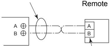
flowchart
graph TD
    A["A ⊕"] --> E["Oval"]
    B["B ⊕"] --> E
    E --> C["A"]
    E --> D["B"]
    C --> E
    D --> E
    style E fill:#f9f,stroke:#333,stroke-width:2px
    note right of E "Remote"
Terminal block (TB07) for remote controller wiring in Hydro unit
Remote controller
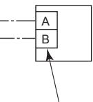
Remote controller wiring (Locally procured)
* Terminals A and B are non-polar.
Second remote controller installation requirements
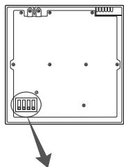
natural_image
Pure electrical circuit lines without any symbolsRemote controller (inside, rear)
DIP switch
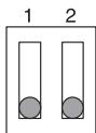
Header remote control/Hot water temperature
DIP switch
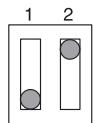
Header remote control/Room temperature
DIP switch
Second remote control/Hot water temperature
DIP switch
Second remote control/Room temperature
Installation
For a dual remote controller system, install the remote controllers in the following way.
- Set one of remote controllers as the header remote controller. (Remote control of hydro unit is preset as Header (DIP SW1 = OFF).)
-
Set the DIP switch on all other remote controller P.C. boards to Second. (Optional remote control is preset as Second (DIP SW1 = ON).)
-
Set DIP SW2 to ON (Room temperature) on the remote control which you will control the room temperature with.
DIP SW2 of optional remote control is preset to ON (Room temperature).
Either one of header or second remote control must be set as room temperature control.
- To control room temperature instead of water temperature with this remote control, set function code "40" of hydro unit to "1".
8 START UP AND CONFIGURATION
Set the DIP switches and function codes.
■ Setting DIP Switches on the Board in the Hydro Unit
- Detach the front cover and the electric parts box cover of the Hydro Unit.
- Set the DIP switches on the main board.
▼ Fig. 8-01
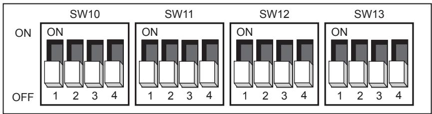
| SW No. | DIP No. | Description | Default | After Commissioning | Change 1 | Change 2 | Change 3 |
| 02 | 1 | Boiler install positionOFF = Heating side after 3 way valveON = Before 3 way valve | OFF | ||||
| 2 | Not Used | - | - | - | - | - | |
| 3 | Not Used | - | - | - | - | - | |
| 4 | Used to when an external room thermostat is connectedOFF = No external room thermostat;ON = External room thermostat connected | OFF | |||||
| 10 | 1 | P1 Pump operation for hot waterOFF = synchronised with heat pumpON = Normally run | OFF | ||||
| 2 | P1 Pump operation for heatingOFF = Normally runON = Stopped at the outside temperature over 20°C | OFF | |||||
| 3 | Synchronisation of Pump P2.OFF = P2 continuous operation (pump off when remote controller switched off)ON = P1 synchronised with pump P1 | OFF | |||||
| 4 | Not Used | - | - | - | - | - | |
| 11 | 1 | Used to activate Hydro Unit back up heaters.OFF = Back up heaters activated;ON = back up heaters de-activated | OFF | ||||
| 2 | Used to activate hot water cylinder electrical heater.OFF = hot water cylinder heater activated;ON = hot water cylinder heater de-activated | OFF | |||||
| 3 | Used to activate external booster heater output.OFF = external booster heater output activated;ON = external booster heater output de-activated | OFF | |||||
| 4 | Not Used | - | - | - | - | - | |
| 12 | 1 | Used when a hot water cylinder is connected to system.OFF = hot water cylinder connected;ON = hot water cylinder not connected | OFF | ||||
| 2 | Used to activate Zone 1 Operation.OFF = Zone 1 activated;ON = Zone 1 de-activated | OFF | |||||
| 3 | Used to activate Zone 2 Operation.OFF = Zone 2 de-activated;ON = Zone activated | OFF | |||||
| 4 | Not Used | - | - | - | - | - | |
| 13 | 1 | Used to determine type of 3 way diverting valve used on system.OFF = 2 SPST type valve;ON = SPDT type valve | OFF | ||||
| 2 | Used to activate external boiler output.OFF = external boiler output de-activated;ON = external boiler output activated | OFF | |||||
| 3 | Used to activate system auto restart after power failure.OFF = auto restart activated;ON = auto restart de-activated | OFF | |||||
| 4 | Not Used | - | - | - | - | - |
■ Setting DIP Switches on the Board in Second Remote controller (option)
- Detach the front cover of the Remote controller.
- Set the DIP switches on the main board
| DIP No. | Description | Default | After Commissioning | Change 1 | Change 2 | Change 3 |
| 1 | Used to when a second remote controller is connected OFF=Header remote control; ON=Second remote control | OFF | - | - | - | - |
| 2 | Used to determine control target when use second remote controllerOFF=water temperature;ON;room temperature | OFF | - | - | - | - |
| 3 | Not Used | - | - | - | - | - |
| 4 | Not Used | - | - | - | - | - |
■ Setting Function Codes for Hydro Unit and Remote Controller
Set function codes for various operation modes with the remote controller.
There are two types of setting.
1) Hydro Unit function code setting
2) Remote controller function code setting
Setting remote controller mode
1 Press the TEST ⏻ + SET ○ + SELECT buttons for four seconds or more to enter the remote controller function code setting mode.

2 Set the function code (CODE No.) with the TEMP. ▼ ▲ buttons. (CODE No.: 01 to 91)
3 Set data (DATA) with the TIME ▼ ▲ buttons.
4 Press the SET ○ button to determine the settings.
5 The CL ○ button is enabled only before the SET ○ button is pressed and the function code is changed.
6 Press the TEST ⏻ button to end the settings.
1 Press the TEST ⬆ + CL ○ + TEMP. ▼ buttons for four seconds or more to enter the remote controller function code setting mode.
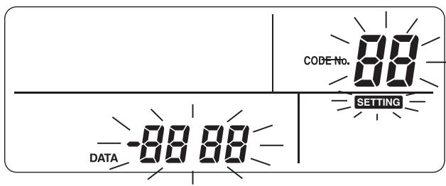
2 Set the function code (CODE No.) with the TEMP. ▼ ▲ buttons. (CODE No.: 01 to 13)
3 Set data (DATA) with the TIME ▼ ▲ buttons.
4 Press the SET ○ button to determine the settings.
5 The CL ○ button is enabled only before the SET ○ button is pressed and the function code is changed.
6 Press the TEST ⏻ button to end the settings.
Main setting items
(1) Setting Hot Water Temperature Range (function code 18 to 1F)
- Set the temperature range for heating (zone 1, zone 2), cooling, and hot water.
- The upper-limit and lower-limit temperatures of each mode can be set.
(2) Setting Heat Pump Operation Conditions for Hot Water Supply (function code 20 and 21)
- Set the heat pump start water temperature and heat pump stop water temperature.
- The heat pump starts working when the water temperature lowers below the set start water temperature. It is recommended that the default value be used.
(3) Compensating Hot Water Temperature (function code 24 and 25)
- Compensate the target temperature from the remote controller set temperature when the hot water temperature lowers below the set outside air temperature.
(4) Setting Hot Water Boost (function code 08 and 09)
- Set the control time and target temperature when the HOT WATER BOOST button on the remote controller is pressed.
(5) Setting Anti-Bacteria
- Set the control for the hot water cylinder when ANTI BACTERIA is set with the remote controller.
- Set the target temperature, control period, start time (24-hour notation), and target temperature retention period.
- Make this control setting according to regulations and rules of respective countries.
(6) Setting Priority Mode Temperature
- Set the outside air temperature that changes the preferred operation mode.
- Hot Water - Heating Switching Temperature Heating operation takes precedence when the temperature lowers the set temperature.
- Boiler HP Switching Temperature When the temperature lowers the set temperature the external boiler output is made.
(7) Setting Heating Auto Mode Temperature (function code 27 to 31)
- Compensate the target temperature when Auto is set for temperature setting on the remote controller.
- The outside air temperature can be set to one of three points (T1 and T3) within a range of -15 to 15°C.
- The target temperature can be set to a value from 20 to 55^ .
• However, A > B > C > D > E.
▼ Fig. 8-02
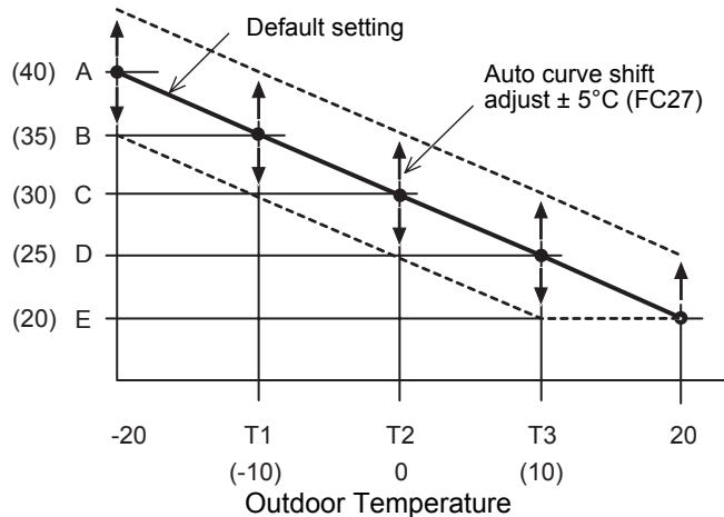
line
| Outdoor Temperature | Value | | ------------------- | ----- | | -20 | 40 | | T1 | 35 | | T2 | 30 | | T3 | 25 | | 20 | 20 |- The entire curve can be adjusted plus and minus 5°C by function code 27.
(8) Setting Frost Protection Temperature (function code 3A to 3B)
- Set the function when the FROST PROTECTION Ⓤ button on the remote controller is pressed.
- Set enabling/disabling of this function and the target water temperature.
- If disabling is set, the frost protection operation is not performed even when the FROST PROTECTION Ⓤ button is pressed.
(9) Setting Frequency of Output to Internal Heater (function code 33 to 34)
- The increase/decrease time is used to set the response time.
(10)Setting Night Setback (function code 26. remote controller function code 0E to 0F)
- Set the function when the NIGHT button on the remote controller is pressed.
- Set enabling/disabling of this function, reduction temperature, start time, and end time.
- If disabling is set, the night setback operation is not performed even when the NIGHT button is pressed.
(12)Hydro 2-Way Diverting valve operation. control
- When using both cooling and heating operations and there is an indoor unit only for heating (such as floor heating), install the 2-way valve and set this function code.
(13)Setting 3way Valve Operation (function code 54)
- This setting is not necessary for normal installation. Make this setting to invert the logic circuit in case ports A and B of the 3-way valve are wrongly attached and it cannot be rectified on site.
(14)Mixing valve operation setting
- Set the time period from full close to full open of the 2-zone control mixing valve. Set a value that is 1/10 of the actual time. And, setting the interval control time. (minutes)
(15)Setting Heating/Hot Water Switching when Boiler Is Used (function code 3E)
- When boiler is used, make this setting to operate the Hydro Unit by the instruction from the boiler.
(16)Setting Heat Pump Operating Time for Hot Water Supply Operation
- Set the time period from the start of heat pump run to the start of heater energization at the beginning of hot water supply operation. If a long period is set, it takes long time for heating water.
(17)Setting Cooling ON/OFF
- Set this function when performing cooling operation.
(18)Remote controller time indication
- 24-hour or 12-hour notation is selected for the timer.
(19)Setting Nighttime Quiet Operation
- Issue an instruction for low-noise mode operation to the outdoor unit. Enabling/disabling of this function, start time, and end time can be set.
(20)Setting Alarm Tone
- The remote controller alarm tone can be set.
(21)Selection of mode of operation by external input.
- Select the logic of an external input signal (option)
Function code settings
| FC Description | Location & FC Number | ||||||||
| Hydro | RC | Range | Default | After Commissioning | Change 1 | Change 2 | |||
| 1 | Setting Temperature Range | Heating Upper Limit - Zone 1 | 1A | - | 37~55°C | 55°C | |||
| Heating Lower Limit - Zone 1 | 1B | - | 20~37°C | 20 | |||||
| Heating Upper Limit - Zone 2 | 1C | - | 37~55°C | 55 | |||||
| Heating Lower Limit - Zone 2 | 1D | - | 20~37°C | 20 | |||||
| Cooling - Upper Limit | 18 | - | 18~30°C | 25 | |||||
| Cooling - Lower Limit | 19 | - | 10~20°C | 10 | |||||
| Hot Water - Upper limit | 1E | - | 60~75°C | 75 | |||||
| Hot Water - Lower limit | 1F | - | 40~60°C | 40 | |||||
| 2 | Hot Water Operation | Heat Pump Start Temperature | 20 | - | 20~45°C | 38 | |||
| Heat Pump Stop Temperature | 21 | - | 40~50°C | 45 | |||||
| 3 | Hot Water Temperature Compensation | Temperature Compensation Outside Air Temperature (°C) | 24 | - | -20~10°C | 0 | |||
| Compensation Temperature (°C) | 25 | - | 0~15°C | 3 | |||||
| 4 | Hot Water Boost | Operation Time (x10 min) | 08 | - | 3~18 | 6 | |||
| Setting Temperature (°C) | 09 | - | 40~75°C | 75 | |||||
| 5 | Anti Bacteria | Setting Temperature (°C) | 0A | - | 65~75°C | 75 | |||
| Start Cycle (Day) | - | 0D | 1~10 | 7 | |||||
| Start Time (Hour) | - | 0C | 0~23 | 22 | |||||
| Operation Time (min) | 0B | - | 0~60 | 30 | |||||
| 6 | Priority Mode | Hot Water & Heating Switching Temperature (°C) | 22 | - | -20~20 | 0 | |||
| Boiler & Heat Pump Switching Temperature (°C) | 23 | - | -20~20 | -10 | |||||
| 7 | Heating Auto Curve Settings | Outside Temperature T1 (°C) | 29 | - | -15~0°C | -10 | |||
| Outside Temperature T2 (°C) | - | - | 0 | 0 | |||||
| Outside Temperature T3 (°C) | 2B | - | 0~15°C | 10 | |||||
| Setting Temperature A @ OAT -20°C (°C) | 2C | - | 20~55°C | 40 | |||||
| Setting Temperature B @ OAT T1 (°C) | 2D | - | 20~55°C | 35 | |||||
| Setting Temperature C @ OAT T2 (°C) | 2E | - | 20~55°C | 30 | |||||
| Setting Temperature D @ OAT T3 (°C) | 2F | - | 20~55°C | 25 | |||||
| Setting Temperature E @ OAT 20°C (°C) | 30 | - | 20~55°C | 20 | |||||
| Ratio Of Zone 2 In Zone 1 Auto Mode (%) | 31 | - | 0~100% | 80 | |||||
| Auto Curve - Temperature Shift (°C) | 27 | - | -5~5°C | 0 | |||||
| 8 | Frost Protection | Function 0=Invalid; 1=Valid | 3A | - | 0~1 | 1 | |||
| Frost Protection Setting Temperature (°C) | 3B | - | 10~20°C | 15 | |||||
| Schedule date (days) | - | 12 | 0~20 | 0 | |||||
| Schedule time (hours) | - | 13 | 0~23 | 0 | |||||
| 9 | Back Up Heater Control | Downtime Back Up Heater 0=5min; 1=10min;2=15min;3=20min | 33 | - | 0~3 | 1 | |||
| Uptime Back Up Heater 0=10min; 1=20min; 2=30min; 3=40min | 34 | - | 0~3 | 0 | |||||
| 10 | Night Setback | Change Setback Temperature | 26 | - | 3~20°C | 5 | |||
| Zone selection 0=Zone 1 & 2; 1= Zone 1 Only | 58 | - | 0~1 | 1 | |||||
| Start Time (Hour) | - | 0E | 0~23 | 22 | |||||
| End Time (Hour) | - | 0F | 0~23 | 06 | |||||
| 12 | Hydro 2 Way Valve Operation Control | Cooling 2 Way Valve - Operation Logic 0=Activated during cooling; 1=Not activated during cooling | 3C | - | 0~1 | 0 | |||
| 13 | Hydro 3 Way Diverting Valve Operation Control | 3 Way Diverting Valve Operation Logic 0=Activated during hot water operation; 1=not activated during hot water operation | 54 | - | 0~1 | 0 | |||
| 14 | 2 Zone Mixing Valve Drive Time | Specified Drive Time for Mixing Valve (x10sec) | 0C | - | 3~24 | 6 | |||
| Mixing valve OFF (control time - mins) | 59 | - | 1~30 | 4 | |||||
| 15 | Boiler/Heat Pump Synchronisation | External Boiler/Heat Pump Synchronisation 0=Synchronised; 1=Not synchronised | 3E | - | 0~1 | 0 | |||
| 16 | Maximum Operation Time Of Hot Water Heat Pump | Maximum Heat Pump Operation Time In Hot Water Operation Priority Mode (minutes) | 07 | - | 1~120 | 30 | |||
| 17 | Cooling Operation | 0=Cooling & Heating Operation; 1=Heating Only Operation | 02 | - | 0~1 | 1 | |||
| 18 | Remote Controller Indication | 24h or 12h Time Indication 0=24h; 1=12h | - | 05 | 0~1 | 0 | |||
| 19 | CDU Night Time Low Noise Operation | Low Noise Operation 0=Invalid; 1=Valid | - | 09 | 0~1 | 0 | |||
| Start Time (Hour) | - | 0A | 0~23 | 22 | |||||
| End Time (Hour) | - | 0B | 0~23 | 06 | |||||
| 20 | Alarm Tone | Tone Switching 0=OFF; 1=ON | - | 11 | 0~1 | 1 | |||
| 21 | E-Stop Switch Logic | 0 = Contacts low > high system stop. System restart with remote controller 1 = Contacts high > low system stop. System restart with remote controller 2 = Contacts high > low system stop. Contacts low > high system restart 3 = Contacts low > high system stop. Contacts low > high (second time) system restart | 52 | - | 0~3 | 0 | |||
| 0 = Restart hot water and heating 1 = Restart in the mode when stopping 2 = Restart hot water 3 = Restart heating 4 = Tempo control 1; without heater 5 = Tempo control 2; without HP and heater | 61 | - | 0~5 | 0 | |||||
| 22 | Hydro Unit Capacity Setting | 0012 = 80*XWH**E 0017 = 140*XWH**E Factory set but function code is needed for PCB replacement or function code reset procedure has been completed. | 01 | - | 0012 or 0017 | Depends on Hydro Unit | |||
| 23 | Second Remote Controller Target temperature Setting | 0=Water temperature1=Room thermo temperature | 40 | - | 0~1 | 0 | |||
| 24 | Room Temperature Sensor Setting | Temperature shift for heating | - | 02 | -10~10 | -1 | |||
| Temperature shift for cooling | - | 03 | -10~10 | -1 | |||||
| 25 | Synchronization control at low outside temperature | 0 = HP + Boiler1 = Boiler2 = Backup heater | 5B | - | 0~2 | 0 | |||
■ Settings by Purpose
Settings when hot water supply function is not used
- When the hot water supply function is not used, set DIP SW12-1 on the Hydro Unit board to ON. (Refer to page 114.)
Setting for cooling
- For Hydro Units that do not perform cooling (those for floor heating, etc.), procure a motorized 2-way valve (for cooling) (refer to “Control parts specifications” on page 105 for the details.) locally and attach it to the water pipe that is not used for cooling. Connect the valve cables to terminals TB05 (3) and (4) of the Hydro Unit.
- Press long the TEST ⬇ + SET ○ + SELECT ◀ ▶ switches on the remote controller to change the Hydro Unit function code, and change address 02 to 0, and then press the SET ○ button to enable the function. Press the TEST ⬇ button to exit the setting mode.
- Stick the optional insulator for cooling to the bottom of the Hydro Unit.
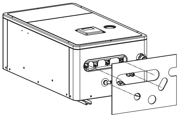
natural_image
Technical line drawing of a device housing with internal components and mounting holes (no text or symbols)Settings for hot water supply
• Prepare the optional hot water cylinder.
- Procure a motorized 3-way valve (refer to “Control parts specifications” on page 105 for the details.) locally and perform piping. Connect the valve cables to terminals TB05 (7), (8) and (9) of the Hydro Unit.
- Set DIP SW12-1 on the Hydro Unit board to OFF. (Refer to page 114.)
- Connect the power supply unit for the hot water cylinder heater to terminals TB03 L and N of the Hydro Unit.
- Connect cables between the Hydro Unit and the hot water cylinder as follows:
Hydro Unit terminals TB03 (1), (2), and earth — Hot water cylinder (1), (2), and earth
TB06 A, B, and earth — Hot water cylinder A, B, and earth
Settings for 2-zone temperature control
- Procure a motorized mixing valve (refer to “Control parts specifications” on page 105 for the details.) locally and perform piping. Connect the valve cables to terminals TB04 (1), (2), (3) and (4) of the Hydro Unit.
- Procure a buffer tank locally.
- Procure a water pump locally, and connect its cables to terminals TB05 (1) and (2) of the Hydro Unit. To inhibit interlocking the water pump with the internal pump of the Hydro Unit, set DIP SW10-3 on the Hydro Unit board to OFF.
- Set DIP SW12-3 on the Hydro Unit board to ON. (Refer to page 114.) Attach the temperature sensor (TFI) connected to terminals TB06 C and D of the Hydro Unit near the hot water inlet of the Hydro Unit.
- Fix TFI sensor on the room heating supply pipe by using the connector procured in locally.
- Cover the cables with insulation tube (minimum 1 mm) or conduit so that the user cannot touch them directly.
- Cover the TFI sensor's cables and sensor with insulation tube (minimum 1 mm) shown in the diagram on the right.
▼ Fig. 8-03
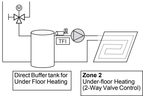
flowchart
graph TD
    A["Direct Buffer tank for Under Floor Heating"] --> B["TF1"]
    B --> C["TF1 Valve"]
    C --> D["Main Plate"]
    style A fill:#f9f,stroke:#333
    style D fill:#ccf,stroke:#333
▼ Fig. 8-04
Insulation tube (minimum 1 mm)
TFI Sensor
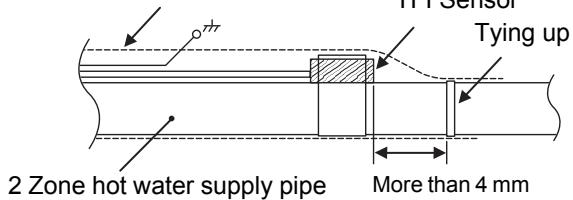
Setting for second remote controller
• Prepare the optional second remote controller.
- Connect the cable to terminals TB07 A,B of theHydro unit and remote controller.
- Set dip switch1 on the second remote controller board to ON.
-
9 TEST RUN
Use operation buttons usually to conduct a test run. If the outside air temperature or water temperature is outside the setting value range, press the TEST 🔍 button on the remote controller and then start a test run. Since the protection setting is disabled in the TEST mode, do not continue a test run longer than 10 minutes.
- Press the TEST ⏻ button on the remote controller. An indication “TEST” appears on the remote controller.
- Press the ZONE1, 2 ⏻ button and select "heating" with the OPERATE MODE ⚙️/💡 button. The pump is activated in 30 seconds. If air is not released completely, the flow rate switch is activated to stop operation. Release air again according to the piping procedure. Little air bite is discharged from the purge valve.
- Check that the air bite sound disappears.
- Check that the hydraulic pressure has become the predetermined pressure 0.1 to 0.2 MPa (1 to 2 bar). If the hydraulic pressure is insufficient, replenish water.
- Heating operation starts. Check that the hydro unit starts heating.
- Press the OPERATE MODE 📞/💡 button and select “cooling.”
- Cooling operation starts. Check that the hydro unit starts cooling and that the floor heating system is not cooled.
- Press the ZONE1, 2 ⏻ button to stop operation.
- Press the HOT WATER ⏻ button to start hot water supply operation.
- Check that there is no air bite.
- Check that hot water is present at the connection port of the hot water cylinder.
- Press the HOT WATER ⏻ button to stop the hot water supply operation.
- Press the TEST ⏻ button to exit the test mode.
10 MAINTENANCE
Execute periodic maintenance at least once a year.
Check points
- Check all electrical connections and make adjustments if they are necessary.
- Check the water pipes of the heating systems in particular any evidence of leakage.
- Check the expansion tank inner pressure. If it is insufficient, enclose nitrogen or dry air in the tank.
- Check that the hydraulic pressure is 0.1 MPa (1 bar) or more with a water manometer. If it is insufficient, replenish tap water.
- Pull the lever of the pressure relief valve and check operation.
- Clean the strainer.
- Check the pump for an abnormal sound or other abnormalities.
11 SENSOR TEMPERATURE MONITORING FUNCTION
The sensor sensing temperature is displayed on the remote controller.
This function allows you to make sure whether the sensor is installed properly.
Press the TEST ⏻ + CL ○ buttons for four seconds or more.
Select the function code with the TEMP. ▼ ▲ buttons.
Press the TEST ⏻ button to exit the test mode.
| Hydro unit data | Item code | Data name | Unit |
| 00 | Control temperature (Hot water cylinder) | °C | |
| 01 | Control temperature (Zone1) | °C | |
| 02 | Control temperature (Zone2) | °C | |
| 03 | Remote controller sensor temperature | °C | |
| 04 | Condensed temperature (TC) | °C | |
| 06 | Water inlet temperature (TWI) | °C | |
| 07 | Water outlet temperature (TWO) | °C | |
| 08 | Water heater outlet temperature (THO) | °C | |
| 09 | Floor inlet temperature (TFI) | °C | |
| 0A | Hot water cylinder temperature (TTW) | °C | |
| 0B | Mixing valve position | step | |
| OE | Low pressure (Ps) × 100 | MPa |
| Hydro unit data | Item code | Data name | Unit |
| F0 | Micro computer energized accumulation time | × 100h | |
| F1 | Hot water compressor ON accumulation time | × 100h | |
| F2 | Cooling compressor ON accumulation time | × 100h | |
| F3 | Heating compressor ON accumulation time | × 100h | |
| F4 | Built-in AC pump operation accumulation time | × 100h | |
| F5 | Hot water cylinder heater operation accumulation time | × 100h | |
| F6 | Backup heater operation accumulation time | × 100h | |
| F7 | Booster heater operation accumulation time | × 100h | |
| 09 | Floor inlet temperature (TFI) | ^ | |
| 0A | Hot water cylinder temperature (TTW) | ^ | |
| 0B | Mixing valve position | step | |
| OE | Low pressure (Ps) × 100 | MPa |
| Outdoor unit data | Item code | Data name | Unit |
| 60 | Heat exchange temperature (TE) | °C | |
| 61 | Outside air temperature (TO) | °C | |
| 62 | Discharge temperature (TD) | °C | |
| 63 | Suction temperature (TS) | °C | |
| 65 | Heat sink temperature (THS) | °C | |
| 6A | Current | A | |
| 6D | Heat exchanger coil temperature (TL) | °C | |
| 70 | Compressor operation Hz | Hz | |
| 72 | Number of revolutions of outdoor fan (lower) | rpm | |
| 73 | Number of revolutions of outdoor fan (upper) | rpm | |
| 74 | Outdoor PMV position × 1/10 | pls |
12 TROUBLESHOOTING
■ Fault Symptoms
| Symptom | Possible cause | Corrective action |
| Room is not heated or cooled.Water is not hot enough. | Incorrect remote controller setting | Check remote controller operation and temperature setting |
| Incorrect function code setting | Check function code setting with the function code table. | |
| Backup heater disconnected | Check backup heater and bimetal thermostat. | |
| Insufficient capacity | Check selection of equipment. | |
| Sensor defect | Check whether temperature sensor is installed at the normal position. | |
| Nothing is displayed on the remote controller. | Power is not supplied. | Check power supply wiring. |
| Incorrect setting | Check DIP switch setting on the Hydro Unit board.Check the setting with the function code table. | |
| Flow rate switch is activated.Error code [A01] | Air bite in the pump | Release air completely according to the procedure. |
| Low hydraulic pressure | Set hydraulic pressure considering pipe height, and replenish water until manometer shows a value of set hydraulic pressure or more. | |
| Strainer is clogged. | Clean the strainer. | |
| Large resistance on the hydro side | Widen water path to the hydro unit or adopt a bypass valve. | |
| Malfunction of motorized 3-way valve for hot water supply | Check wiring and parts. | |
| Hot water leaks from pressure relief valve. | Excessive hydraulic pressure | Set hydraulic pressure considering pipe height, and replenish water until manometer shows a value of set hydraulic pressure or more. |
| Insufficient capacity of expansion tank | Check expansion tank capacity compared to total water amount. If it is insufficient, install another expansion tank. | |
| Expansion tank failure | Check the air pressure. |
Defect mode detected by the water heat exchange
O ... Possible
× .... Not possible
| Check code | Diagnostic functional operation | Determination and action | ||
| Operational cause | Backup present | Automatic reset | ||
| A01 | Pump or flowing quantity error1) Detected by TC sensor (TC ≥ 63°C) | × | × | 1. Almost no or little water flow.· Not enough vent air· Dirt clogging in the water piping system.· The water piping is too long.· Installation of buffer tank and secondary pump |
| 2)Detected by flow switch abnormality | ||||
| 3)Detection of chattering abnormality in the flow switch input | ||||
| 4)Disconnection of the flow switch connector | 1. Disconnection of the flow switch connector.2. Defect of the flow switch. | |||
| A02 | Temperature increase error (heating)(TWI, TWO, THO) | HeatingOHot water× | O | 1. Check the water inlet, water outlet and heater outlet (TWI, TWO, THO) sensors.2. Defect of the backup heater (defect automatic reset thermostat). |
| A03 | Temperature increase error (hot water supply)(TTW) | HeatingOHot water× | O | 1. Check the hot water cylinder sensor (TTW).2. Check the hot water cylinder thermal cut-out. |
O ... Possible
× .... Not possible
| Check code | Diagnostic functional operation | Determination and action | ||
| Operational cause | Backup present | Automatic reset | ||
| A04 | Antifreeze operation | O | × | 1. Almost no or little water flow.• Dirt clogging in the water piping system.• The water piping is too long.2. Check the heater power circuit.• Power supply voltage, breaker, power supply connection3. Set the presence of the backup heater.4. Check the water inlet, water outlet and heat exchange (TWI, TWO, TC) sensors. |
| A05 | Piping antifreeze operation | O | O | 1. Check the heater power circuit.• Power supply voltage, breaker, power supply connection2. Check the water inlet, water outlet and heater outlet sensors (TWI, TWO, THO).3. Disconnection of the backup heater. |
| A07 | Pressure switch operation | O | × | 1. Almost no or little water flow.2. Defect of the flow switch.3. On-load operation under the above conditions.4. Defect in the pressure switch. |
| A08 | Low pressure sensor operation error | O | × | 1. Almost no or little water flow.2. Defect of the flow switch.3. On-load cooling or prolonged defrosting (a lot of frost formation) under the above conditions. |
| 4. Defect in the low pressure sensor. | ||||
| A09 | Overheat protection operation (Thermostat of the backup heater) | O | × | 1. No water (heating without water) or no water flow.2. Defect of the flow switch. |
| 3. Defect of the backup heater (poor automatic reset thermostat). | ||||
| A11 | Operation of the release protection | Heating Cooling × Hot water O | × | 1. Almost no water flow.2. Defect of the flow switch.3. Check the water outlet temperature sensor (TWO). |
| A12 | Heating, hot water heater error | O | O | 1. Activated by a large load of heating or hot water supply.2. Check the heater power circuit (backup or hot water cylinder heater).• Power supply voltage, breaker, power supply connection |
| E03 | Regular communication error between hydro unit and remote controller | × | O | 1. Check remote control connection.2. Defect in the remote control. |
| E04 | Regular communication error between hydro unit and outdoor unit | O | O | 1. Check the serial circuit.• Miswiring of the crossover between the water heat exchanger and the outdoor unit |
| F03 | TC sensor error | O | O | 1. Check the resistance value and connection of the heat exchange temperature sensor (TC). |
| F10 | TWI sensor error | O | O | 1. Check the resistance value and connection of the water inlet temperature sensor (TWI). |
| F11 | TWO sensor error | × | O | 1. Check the resistance value and connection of the water outlet temperature sensor (TWO). |
O ... Possible
× .... Not possible
| Check code | Diagnostic functional operation | Determination and action | ||
| Operational cause | Backup present | Automatic reset | ||
| F14 | TTW sensor error | × | O | 1. Check the resistance value and connection of the hot water cylinder sensor (TTW). |
| F17 | TFI sensor error | × | O | 1. Check the resistance value and connection of the floor-inlet temperature sensor (TFI). |
| F18 | THO sensor error | × | O | 1. Check the resistance value and connection of the heater outlet temperature sensor (THO). |
| F19 | Detection of THO disconnection error | × | × | 1. Check for any disconnection of the heater outlet temperature sensor (THO). |
| F20 | TFI sensor error | × | × | 1. Check the connection of the floor-inlet temperature sensor (TFI). |
| F23 | Low pressure sensor error | O | O | 1. Check the connection (body or connection wiring) of the low pressure sensor.2. Check the resistance value of the low pressure sensor. |
| F29 | EEROM error | × | × | 1. Replace the water heat exchange control board. |
| F30 | Extended IC error | × | × | 1. Replace the water heat exchange control board. |
| L07 | Communication error | × | × | 1. Replace the water heat exchange control board. |
| L09 | Communication error | × | × | 1. Check the setting of the FC01 capability specifications.HWS-803xx-E = 0012HWS-1403xx-E = 0017 |
| L16 | Setting errorWhen ZONE1 has not been set, while ZONE2 has been set. | × | × | 1. Check the body DP-SW12_2,3. |
Defect mode detected by the water heat exchange
| Check code | Diagnostic functional operation | Determination and action | ||
| Operational cause | Backup present | Automatic reset | ||
| F04 | TD sensor error | O | × | 1. Check the resistance value and connection of the discharge sensor (TD). |
| F06 | TE sensor error | O | × | 1. Check the resistance value and connection of the heat exchange temperature sensor (TE). |
| F07 | TL sensor error | O | × | 1. Check the resistance value and connection of the heat exchange temperature sensor (TL). |
| F08 | TO sensor error | O | × | 1. Check the resistance value and connection of the outdoor temperature sensor (TO). |
| F12 | TS sensor error | O | × | 1. Check the resistance value and connection of the suction temperature sensor (TS). |
| F13 | TH sensor error | O | × | 1. Check the resistance value and connection of the heat-sink temperature sensor (TH). |
| F15 | TE, TS sensors error | O | × | 1. Check for any wrong installation of the heat exchange temperature sensor (TE) and the suction temperature sensor (TS). |
| F31 | EEPROM error | O | × | |
| H01 | Compressor breakdown | O | × | 1. Check the power supply voltage.2. Over-loaded condition of the refrigeration cycle.3. Check that the service valve is fully open. |
| H02 | Compressor lock | O | × | 1. Defect of compressor (lock)– Replace the compressor.2. Defect of compressor wiring (open phase). |
| H03 | Defect in the current detection circuit | O | × | 1. Replace the outdoor inverter control board. |
| H04 | Operation of case thermostat | O | × | 1. Check the refrigeration cycle (gas leak).2. Check the case thermostat and connector.3. Check that the service valve is fully open.4. Defect of the pulse motor valve.5. Check for kinked piping. |
| L10 | Unset service PC board jumper Jumpers have not been cut. | O | × | 1. Cut outdoor PC board jumper wire (for service). |
| L29 | The communication between the outdoor PC board MUCs error | O | × | 1. Replace the outdoor control board. |
| P03 | The outlet temperature error | O | × | 1. Check the refrigeration cycle (gas leak).2. Defect of the pulse motor valve.3. Check the resistance value of the discharge temperature sensor (TD). |
| P04 | The high pressure switch error | O | × | |
| P05 | The power supply voltage error | O | × | 1. Check the power supply voltage. |
| P07 | Overheating of heat-sink error | O | × | 1. Check the thread fastening and heat-sink grease between the outdoor control board and the heat-sink.2. Check the heat-sink fan duct.3. Check the resistance value of the heat-sink temperature sensor (TH). |
| P15 | Detection of gas leak | O | × | 1. Check the refrigeration cycle (gas leak).2. Check that the service valve is fully open.3. Defect of the pulse motor valve.4. Check for kinked piping.5. Check the resistance value of the discharge temperature sensor (TD) and the suction temperature sensor (TS). |
| P19 | The 4-way valve inversion error | O | × | 1. Check the operation of the 4-way valve unit or the coil characteristics.2. Defect of the pulse motor valve.3. Check the resistance value of the heat exchange temperature sensor (TE) and the suction temperature sensor (TS). |
| P20 | High pressure protection operation | O | × | 1. Check that the service valve is fully open.2. Defect of the pulse motor valve.3. Check the outdoor fan system (including clogging).4. Over-filling of refrigerant.5. Check the resistance value of the heat exchange temperature sensor (TL) and the water outlet temperature sensor (TWO). |
| P22 | Outdoor fan system error | O | × | 1. Check the lock status of the motor fan.2. Check the connection of the fan motor cable connector.3. Check the power supply voltage. |
| P26 | Short circuit of the compressor driver element error | O | × | 1. Abnormality occurs when operating with the compressor wiring disconnected ... Check the control board.2. No abnormality occurs when operating with the compressor wiring disconnected ... Compressor rare short. |
| P29 | Compressor rotor position error | O | × | 1. Even if the connection lead wire of the compressor is disconnected, it stops due to an abnormality in the position detection ... Replace the inverter control board.2. Check the wire wound resistor of the compressor. Short circuit... Replace the compressor. |
Defect mode detected by the remote control
| Check code | Diagnostic functional operation | Determination and action | ||
| Operational cause | Status of air-conditioning | Condition | ||
| Not displaying at all (cannot operate by the remote control) | No communication between hydro unit an remote controller | Stop | - | Defect in the remote control power supply1. Check the remote controller wiring.2. Check the remote controller.3. Check the hydro unit power supply wiring.4. Check the water heat exchange control board. |
| E01 | No communication between hydro unit and remote controller | Stop (Automatic reset) | Displayed when the abnormality is detected. | Defect in the reception of the remote control1. Check the remote control crossover.2. Check the remote control.3. Check the hydro power supply wiring.4. Check the water heat exchanger board. |
| E02 | Defect in the signal transmission to the hydro unit.(Detected on the remote control side) | Stop (Automatic reset) | Displayed when the abnormality is detected. | Defect in the transmission of the remote control1. Check the transmitter circuit inside the remote control... Replace the remote control. |
| E09 | Several remote control base units(Detected on the remote control side) | Stop (The handset continues) | Displayed when the abnormality is detected. | 1.2 Check several base units with the remote control... The base unit is only one, and others are handsets. |
MEMO
8. OUTDOOR UNIT INSTALLATION MANUAL
TOSHIBA
Leading Innovation >>>

AIR TO WATER HEAT PUMP
Installation manual
HFC
R410A
Outdoor Unit
Model name:
HWS-803H-E
HWS-1103H-E
HWS-1403H-E
HWS-1103H8-E
HWS-1403H8-E
HWS-1603H8-E
HWS-1103H8R-E
HWS-1403H8R-E
HWS-1603H8R-E
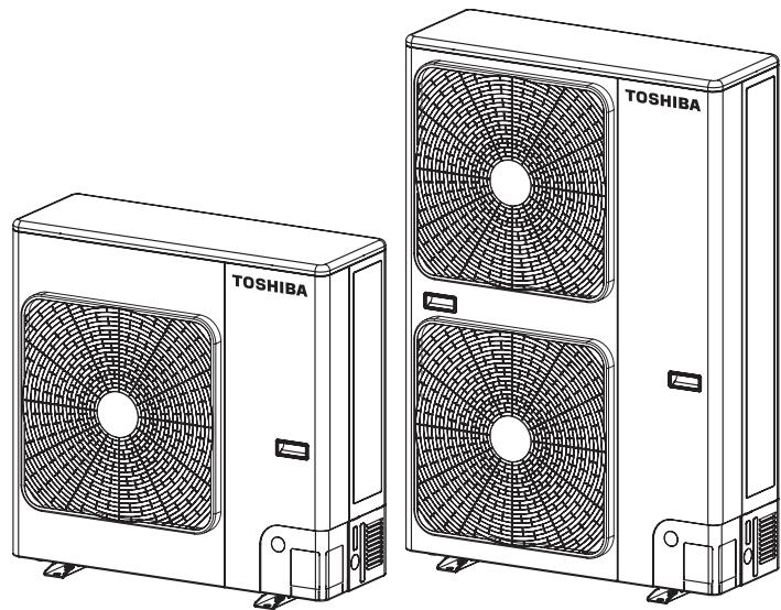
natural_image
Line drawings of two TOSHIBA air conditioning units with fan blades (no text or symbols)Please read this Installation Manual carefully before installing the Air to Water Heat Pump.
- This Manual describes the installation method of the outdoor unit.
- For installation of the hydro unit, follow the Installation Manual attached to the hydro unit.
Original instruction
ADOPTION OF NEW REFRIGERANT
This Air to water heat pump is a new type that has adopted a new refrigerant HFC (R410A) instead of the conventional refrigerant R22 in order to prevent destruction of the ozone layer.
▼ HWS-803H-E, HWS-1103H-E, HWS-1403H-E
Equipment complying with IEC 610003-12.
▼ HWS-1103H8-E, HWS-1103H8R-E HWS-1403H8-E, HWS-1403H8R-E HWS-1603H8-E, HWS-1603H8R-E
This equipment complies with IEC 61000-3-12 provided that the short-circuit power Ssc is greater than or equal to Ssc (*1) at the interface point between the user's supply and the public system. It is the responsibility of the installer or user of the equipment to ensure, by consultation with the distribution network operator if necessary, that the equipment is connected only to a supply with a short-circuit power Ssc greater than or equal to Ssc (*1).
Furthermore, when similar equipment or other equipment which may cause harmonic current emissions are to be connected to the same interface point with this equipment, to reduce the risk of possible problems which may be caused from addition of those harmonic current emissions, it is recommended to make sure that the short-circuit power Ssc at the interface point is greater than the sum of the minimum Ssc required by all the equipment which will be connected to the interface point.
Ssc (*1)
| Model | Ssc (MVA) |
| HWS-1103H8-E, HWS-1103H8R-E | 0.71 |
| HWS-1403H8-E, HWS-1403H8R-E | 0.71 |
| HWS-1603H8-E, HWS-1603H8R-E | 0.71 |
Contents
1 PRECAUTIONS FOR SAFETY.... 138
2 ACCESSORY PARTS AND REFRIGERANT....140
3 INSTALLATION OF NEW REFRIGERANT AIR TO WATER HEAT PUMP ..... 141
4 INSTALLATION CONDITIONS....142
5 REFRIGERANT PIPING 146
6 AIR PURGING....149
7 ELECTRICAL WORK....151
8 EARTHING 154
9 FINISHING....154
10 TEST RUN....154
11 ANNUAL MAINTENANCE 154
12 AIR TO WATER HEAT PUMP OPERATING CONDITIONS ..... 154
13 FUNCTIONS TO BE IMPLEMENTED LOCALLY.... 155
14 TROUBLESHOOTING 156
15 APPENDIX 158
■ Generic Denomination: Air to water heat pump
■ Definition of Qualified Installer or Qualified Service Person
The air to water heat pump must be installed, maintained, repaired and removed by a qualified installer or qualified service person. When any of these jobs is to be done, ask a qualified installer or qualified service person to do them for you.
A qualified installer or qualified service person is an agent who has the qualifications and knowledge described in the table below.
| Agent | Qualifications and knowledge which the agent must have |
| Qualified installer | The qualified installer is a person who installs, maintains, relocates and removes the air to water heat pumps made by Toshiba Carrier Corporation. He or she has been trained to install, maintain, relocate and remove the air to water heat pump made by Toshiba Carrier Corporation or, alternatively, he or she has been instructed in such operations by an individual or individuals who have been trained and is thus thoroughly acquainted with the knowledge related to these operations.The qualified installer who is allowed to do the electrical work involved in installation, relocation and removal has the qualifications pertaining to this electrical work as stipulated by the local laws and regulations, and he or she is a person who has been trained in matters relating to electrical work on the air to water heat pump made by Toshiba Carrier Corporation or, alternatively, he or she has been instructed in such matters by an individual or individuals who have been trained and is thus thoroughly acquainted with the knowledge related to this work.The qualified installer who is allowed to do the refrigerant handling and piping work involved in installation, relocation and removal has the qualifications pertaining to this refrigerant handling and piping work as stipulated by the local laws and regulations, and he or she is a person who has been trained in matters relating to refrigerant handling and piping work on the air to water heat pump made by Toshiba Carrier Corporation or, alternatively, he or she has been instructed in such matters by an individual or individuals who have been trained and is thus thoroughly acquainted with the knowledge related to this work.The qualified installer who is allowed to work at heights has been trained in matters relating to working at heights with the air to water heat pump made by Toshiba Carrier Corporation or, alternatively, he or she has been instructed in such matters by an individual or individuals who have been trained and is thus thoroughly acquainted with the knowledge related to this work. |
| Qualified service person | The qualified service person is a person who installs, repairs, maintains, relocates and removes the air to water heat pump made by Toshiba Carrier Corporation. He or she has been trained to install, repair, maintain, relocate and remove the air to water heat pump made by Toshiba Carrier Corporation or, alternatively, he or she has been instructed in such operations by an individual or individuals who have been trained and is thus thoroughly acquainted with the knowledge related to these operations.The qualified service person who is allowed to do the electrical work involved in installation, repair, relocation and removal has the qualifications pertaining to this electrical work as stipulated by the local laws and regulations, and he or she is a person who has been trained in matters relating to electrical work on the air to water heat pump made by Toshiba Carrier Corporation or, alternatively, he or she has been instructed in such matters by an individual or individuals who have been trained and is thus thoroughly acquainted with the knowledge related to this work.The qualified service person who is allowed to do the refrigerant handling and piping work involved in installation, repair, relocation and removal has the qualifications pertaining to this refrigerant handling and piping work as stipulated by the local laws and regulations, and he or she is a person who has been trained in matters relating to refrigerant handling and piping work on the air to water heat pump made by Toshiba Carrier Corporation or, alternatively, he or she has been instructed in such matters by an individual or individuals who have been trained and is thus thoroughly acquainted with the knowledge related to this work.The qualified service person who is allowed to work at heights has been trained in matters relating to working at heights with the air to water heat pump made by Toshiba Carrier Corporation or, alternatively, he or she has been instructed in such matters by an individual or individuals who have been trained and is thus thoroughly acquainted with the knowledge related to this work. |
■ Definition of Protective Gear
When the air to water heat pump is to be transported, installed, maintained, repaired or removed, wear protective gloves and “safety” work clothing.
In addition to such normal protective gear, wear the protective gear described below when undertaking the special work detailed in the table below.
Failure to wear the proper protective gear is dangerous because you will be more susceptible to injury, burns, electric shocks and other injuries.
| Work undertaken | Protective gear worn |
| All types of work | Protective gloves“Safety” working clothing |
| Electrical-related work | Gloves to provide protection for electricians and from heatInsulating shoesClothing to provide protection from electric shock |
| Work done at heights (50 cm or more) | Helmets for use in industry |
| Transportation of heavy objects | Shoes with additional protective toe cap |
| Repair of outdoor unit | Gloves to provide protection for electricians and from heat |
Warning Indications on the Air to water heat pump Unit
| Warning indication | Description | |
 | WARNING | WARNING ELECTRICAL SHOCK HAZARD Disconnect all remote electric power supplies before servicing. |
| ELECTRICAL SHOCK HAZARD Disconnect all remote electric power supplies before servicing. | ||
 | WARNING | WARNING Moving parts.Do not operate unit with grille removed.Stop the unit before the servicing. |
| Moving parts.Do not operate unit with grille removed.Stop the unit before the servicing. | ||
 | CAUTION | CAUTIONHigh temperature parts.You might get burned when removing this panel. |
| High temperature parts.You might get burned when removing this panel. | ||
 | CAUTION | CAUTIONDo not touch the aluminum fins of the unit.Doing so may result in injury. |
| Do not touch the aluminum fins of the unit.Doing so may result in injury. | ||
 | CAUTION | CAUTIONBURST HAZARDOpen the service valves before the operation, otherwise there might be the burst. |
| BURST HAZARD | ||
1 PRECAUTIONS FOR SAFETY
- Ensure that all Local, National and International regulations are satisfied.
- Read this "PRECAUTIONS FOR SAFETY" carefully before Installation.
- The precautions described below include the important items regarding safety. Observe them without fail.
- After the installation work, perform a trial operation to check for any problem. Follow the Owner's Manual to explain how to use and maintain the unit to the customer.
- Turn off the main power supply switch (or breaker) before the unit maintenance.
- Ask the customer to keep the Installation Manual together with the Owner's Manual.

WARNING
- Ask an authorized dealer or qualified installation professional to install/maintain the Air to Water Heat Pump. Inappropriate installation may result in water leakage, electric shock or fire.
- Be sure to connect earth wire. (grounding work) Incomplete grounding cause an electric shock. Do not connect ground wires to gas pipes, water pipes, lightning rods or ground wires for telephone wires.
- Turn off the main power supply switch or breaker before attempting any electrical work. Make sure all power switches are off. Failure to do so may cause electric shock. Use an exclusive power circuit for the Air to Water Heat Pump. Use the rated voltage.
- Connect the connecting wire correctly. If the connecting wire is connected in a wrong way, electric parts may be damaged.
- When moving the Air to Water Heat Pump for the installation into another place, be very careful not to enter any gaseous matter other than the specified refrigerant into the refrigeration cycle. If air or any other gas is mixed in the refrigerant, the gas pressure in the refrigeration cycle becomes abnormally high and it may resultingly causes pipe burst and injuries on persons.
- Do not modify this unit by removing any of the safety guards or by by-passing any of the safety interlock switches.
• After unpacking the unit, examine it carefully if there are possible damage. - Do not install in a place that might increase the vibration of the unit.
- To avoid personal injury (with sharp edges), be careful when handling parts.
- Perform installation work properly according to the Installation Manual. Inappropriate installation may result in water leakage, electric shock or fire.
- When the Air to Water Heat Pump hydro unit is installed in a small room, provide appropriate measures to ensure that the concentration of refrigerant leakage occur in the room does not exceed the critical level.
- Tighten the flare nut with a torque wrench in the specified manner. Excessive tightening of the flare nut may cause a crack in the flare nut after a long period, which may result in refrigerant leakage.
- Wear heavy gloves during the installation work to avoid injury.
• Install the Air to Water Heat Pump securely in a location where the base can sustain the weight adequately. - Perform the specified installation work to guard against an earthquake. If the Air to Water Heat Pump is not installed appropriately, accidents may occur due to the falling unit.
- If refrigerant gas has leaked during the installation work, ventilate the room immediately. If the leaked refrigerant gas comes in contact with fire, noxious gas may generate.
- After the installation work, confirm that refrigerant gas does not leak. If refrigerant gas leaks into the room and flows near a fire source, such as a cooking range, noxious gas might generate.
- Electrical work must be performed by a qualified electrician in accordance with the Installation Manual. Make sure the Air to Water Heat Pump uses a dedicated power supply.
An insufficient power supply capacity or inappropriate installation may cause fire.
- Use the specified wires for wiring connect the terminals securely fix. To prevent external forces applied to the terminals from affecting the terminals.
- When the Air to Water Heat Pump cannot cool or heat water well, contact the dealer from whom you purchased the Air to Water Heat Pump as refrigerant leakage is considered as the cause. In the case of repair that requires refill of refrigerant, ask service personnel about details of the repair.
The refrigerant used in the Air to Water Heat Pump is harmless.
Generally, the refrigerant does not leak. However, if the refrigerant leaks in a room and a heater or stove burner in the room catches fire, it may generate toxic gas.
When you ask service personnel for repairing refrigerant leakage, confirm that the leakage portion has been completely repaired.
- Conform to the regulations of the local electric company when wiring the power supply.
Inappropriate grounding may cause electric shock. - Do not install the Air to Water Heat Pump in a location subject to a risk of exposure to a combustible gas. If a combustible gas leaks, and stays around the unit, a fire may occur.
- Install the refrigerant pipe securely during the installation work before operating the Air to Water Heat Pump. If the compressor is operated with the valve open and without the refrigerant pipe, the compressor sucks air and the refrigeration cycle is overpressurized, which may cause a burst or injury.
- For the refrigerant recovery work (collection of refrigerant from the pipe to the compressor), stop the compressor before disconnecting the refrigerant pipe.
If the refrigerant pipe is disconnected while the compressor is working with the valve open, the compressor sucks air and the refrigeration cycle is overpressurized, which may cause a burst or injury.

CAUTION
New Refrigerant Air to Water Heat Pump Installation
- THIS AIR TO WATER HEAT PUMP ADOPTS THE NEW HFC REFRIGERANT (R410A) WHICH DOES NOT DESTROY OZONE LAYER.
- The characteristics of R410A refrigerant are; easy to absorb water, oxidizing membrane or oil, and its pressure is approx. 1.6 times higher than that of refrigerant R22. Accompanied with the new refrigerant, refrigerating oil has also been changed. Therefore, during installation work, be sure that water, dust, former refrigerant, or refrigerating oil does not enter the refrigerating cycle.
- To prevent charging an incorrect refrigerant and refrigerating oil, the sizes of connecting sections of charging port of the main unit and installation tools are changed from those for the conventional refrigerant.
- Accordingly the exclusive tools are required for the new refrigerant (R410A).
- For connecting pipes, use new and clean piping designed for R410A, and please care so that water or dust does not enter.
To Disconnect the Appliance from Main Power Supply
- This appliance must be connected to the main power supply by means of a switch with a contact separation of at least 3 mm.
- The installation fuse must be used for the power supply line of this unit.
2 ACCESSORY PARTS AND REFRIGERANT
■ Accessory Parts
| Part name | Q'ty | Shape | Usage |
| Outdoor unit installation manual | 1 | [0245] | Hand this directly to the customer.(For other languages that do not appear in this Installation Manual, please refer to the enclosed CD-R.) |
| Drain nipple | 1 |  | |
| Waterproof rubber cap | 5 |  | |
| Protective bush | 1 |  | For protecting wires (pipe cover) |
| Guard material for passage part | 1 | [7ZW] | For protecting passage part (pipe cover) |
| Clamp filter | (1)* |  | For conforming to EMC standards(Used for power wire) |
* HWS-1103H8-E, 1103H8R-E
HWS-1403H8-E, 1403H8R-E
HWS-1603H8-E, 1603H8R-E
3 INSTALLATION OF NEW REFRIGERANT AIR TO WATER HEAT PUMP
- The R410A refrigerant is more susceptible to impurities such as water, oxide membranes, oils, and fats. With the adoption of the new refrigerant, the refrigerating oil has also been changed. Be careful not to let water, dust, conventional refrigerant, and/or conventional refrigerating oil enter the refrigerating cycle of the new refrigerant air to water heat pump.
- To prevent different refrigerant or refrigerating oil from becoming mixed, the sizes of the charging port of the unit and the installation tool connection sections are different from those of the conventional refrigerant. Accordingly, the following exclusive tools are required for the new refrigerant R410A.
■ Required Tools/Equipment and Precautions for Use
Prepare the tools and equipment listed in the following table before starting the installation work.
Newly prepared tools and equipment must be used exclusively.
Legend
△ : Prepared newly (Use for R410A only. Do not use for refrigerant R22 or R407C etc.)
◎ : Conventional tools/equipment are available
| Tools/equipment | Use | How to use tools/equipment |
| Gauge manifold | Vacuuming/charging refrigerant and operation check | Prepared newly for R410A only |
| Charging hose | Prepared newly for R410A only | |
| Charging cylinder | Can not be used | Unusable (Use the refrigerant charging measure instead.) |
| Gas leak detector | Gas leak check | Prepared newly |
| Vacuum pump | Vacuum drying | Unusable |
| Vacuum pump with backflow prevention function | Vacuum drying | R22 (Conventional tools) |
| Flare tool | Flare machining of pipes | Usable if dimensions are adjusted. |
| Bender | Bending pipes | R22 (Conventional tools) |
| Refrigerant recovery equipment | Refrigerant recovery | For R410A only |
| Torque wrench | Tightening flare nuts | Exclusive for 12.7 mm and 15.9 mm |
| Pipe cutter | Cutting pipes | R22 (Conventional tools) |
| Welding machine and nitrogen cylinder | Welding pipes | R22 (Conventional tools) |
| Refrigerant charging measure | Charging refrigerant | R22 (Conventional tools) |
■ Refrigerant Piping
New refrigerant (R410A)
When using the conventional piping kit
- When using the conventional piping kit with no indication of applicable refrigerant types, be sure to use it with a wall thickness of 0.8 mm for ∅6.4 mm, ∅9.5 mm, and ∅12.7 mm, and with a wall thickness of 1.0 mm for ∅15.9 mm. Do not use the conventional piping kit with a wall thickness less than these thicknesses due to insufficient pressure capacity.
When using general copper pipes
- Use general copper pipes with a wall thickness of 0.8 mm for ∅6.4 mm, ∅9.5 mm, and ∅12.7 mm, and with a wall thickness of 1.0 mm for ∅15.9 mm. Do not use any copper pipes with a wall thickness less than these thicknesses.
Flare nuts and flare machining
- The flare nuts and flare machining are different from those for the conventional refrigerant. Use the flare nuts supplied with the air to water heat pump or those for R410A. - Before performing flare machining, carefully read “REFRIGERANT PIPING”.
4 INSTALLATION CONDITIONS
■ Before installation
Be sure to prepare to the following items before installation.
Length of refrigerant pipe
| Length of refrigerant pipe connected to indoor/outdoor unit | Item |
| 5 to 30 m | Addition of refrigerant is unnecessary at the local site. |
- Do not connect a refrigerant pipe that is shorter than 5 m. This may cause a malfunction of the compressor or other devices.
■ Airtight test
- Before starting an airtight test, further tighten the spindle valves on the gas and liquid sides.
- Pressurize the pipe with nitrogen gas charged from the service port to the design pressure (4.15 MPa) to conduct an airtight test.
- After the airtight test is completed, evacuate the nitrogen gas.
Air purge
- To purge air, use a vacuum pump.
- Do not use refrigerant charged in the outdoor unit to purge air. (The air purge refrigerant is not contained in the outdoor unit.)
Electrical wiring
- Be sure to fix the power wires and hydro/outdoor connecting wires with clamps so that they do not come into contact with the cabinet, etc.
Earthing
- Proper earthing can prevent charging of electricity on the outdoor unit surface due to the presence of a high frequency in the frequency converter (inverter) of the outdoor unit, as well as prevent electric shock. If the outdoor unit is not properly earthed, you may be exposed to an electric shock.
- Be sure to connect the earth wire. (grounding work)
Incomplete earthing can cause an electric shock. Do not connect earth wires to gas pipes, water pipes, lightning rods or earth wires for telephone wires.
Test Run
Turn on the leakage breaker at least 12 hours before starting a test run to protect the compressor during startup.
■ Installation Location

CAUTION
Install the outdoor unit in a location that meets the following conditions after the customer's consent is obtained.
- A well-ventilated location free from obstacles near the air inlets and air outlet
- A location that is not exposed to rain or direct sunlight
- A location that does not increase the operating noise or vibration of the outdoor unit
- A location that does not produce any drainage problems from discharged water
Do not install the outdoor unit in the following locations.
- A location with a saline atmosphere (coastal area) or one that is full of sulfide gas (hot-spring area) (Special maintenance is required.)
- A location subject to oil, vapor, oily smoke, or corrosive gases
• A location in which organic solvent is used - A location where high-frequency equipment (including inverter equipment, private power generator, medical equipment, and communication equipment) is used (Installation in such a location may cause malfunction of the air to water heat pump, abnormal control or problems due to noise from such equipment.)
- A location in which the discharged air of the outdoor unit blows against the window of a neighboring house
- A location where the operating noise of the outdoor unit is transmitted
- When the outdoor unit is installed in an elevated position, be sure to secure its feet.
-
A location in which drain water poses any problems.
-
Install the outdoor unit in a location where the discharge air is not blocked.
- When an outdoor unit is installed in a location that is always exposed to strong winds like a coast or on the high stories of a building, secure normal fan operation by using a duct or wind shield.
- When installing the outdoor unit in a location that is constantly exposed to strong winds such as on the upper stairs or rooftop of a building, apply the windproofing measures referred to in the following examples.
1) Install the unit so that its discharge port faces the wall of the building.
Keep a distance 500 mm or more between the unit and wall surface.
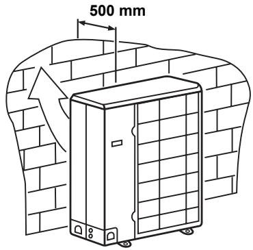
2) Consider the wind direction during the operational season of the Air to water Heat Pump, and install the unit so that the discharge port is set at a right angle relative to the wind direction.
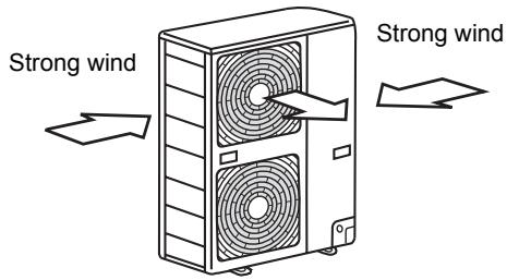
- When installing the unit in an area where snowfalls may be heavy, take steps to prevent the unit from being adversely affected by the fallen or accumulated snow.
- Either make the foundation higher or install a stand (which is high enough to ensure that the unit will be above the fallen or accumulated snow) and place the unit on it.
- Attach a snow shield (locally procured).
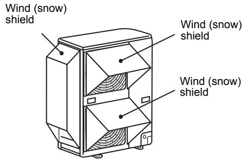
■ Necessary Space for Installation
(Unit: mm)
Obstacle at rear side
Upper side is free
- Single unit installation
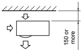
- Obstacles on both right and left sides
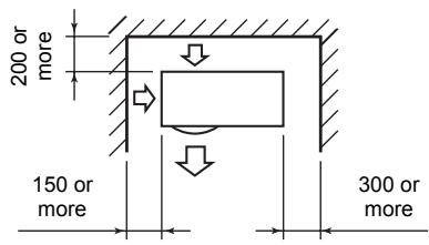
The height of the obstacle should be lower than the height of the outdoor unit.
- Serial installation of two or more units
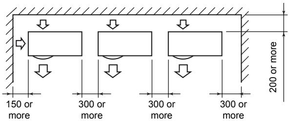
The height of the obstacle should be lower than the height of the outdoor unit.
Obstacle also above unit
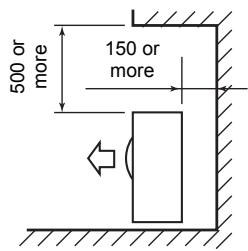
Obstacle in front
Above unit is free
- Single unit installation
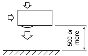
- Serial installation of two or more units
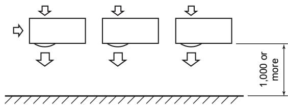
Obstacle also at the above unit
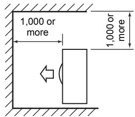
Obstacles in both front and rear of unit
Open above and to the right and left of the unit.
The height of an obstacle in both the front and rear of the unit, should be lower than the height of the outdoor unit.
Standard installation
- Single unit installation
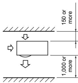
2. Serial installation of two or more units
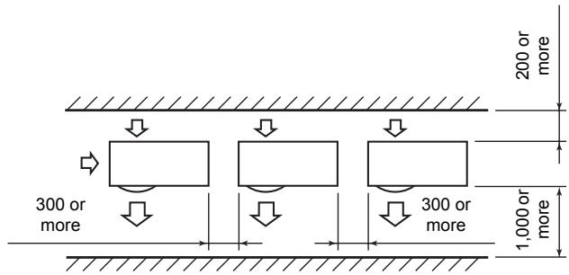
Serial installation in front and rear
Open above and to the right and left of the unit.
The height of an obstacle in both the front and rear of the unit should be lower than the height of the outdoor unit.
Standard installation
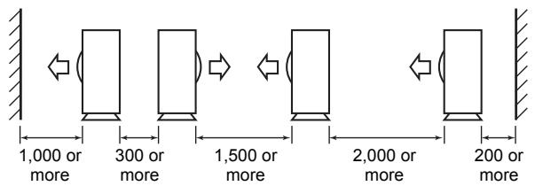
■ Installation of Outdoor Unit
- Before installation, check the strength and horizontalness of the base so that abnormal sounds do not emanate.
- According to the following base diagram, fix the base firmly with the anchor bolts.
- (Anchor bolt, nut: M10 x 4 pairs)
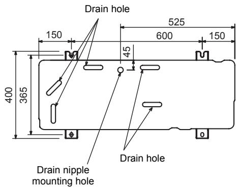
- As shown in the figure below, install the foundation and vibration-proof rubber pads to directly support the bottom surface of the fixing leg that is in contact with and underneath the bottom plate of the outdoor unit.
* When installing the foundation for an outdoor unit with downward piping, consider the piping work.
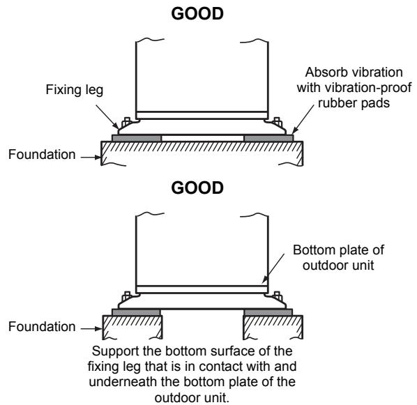
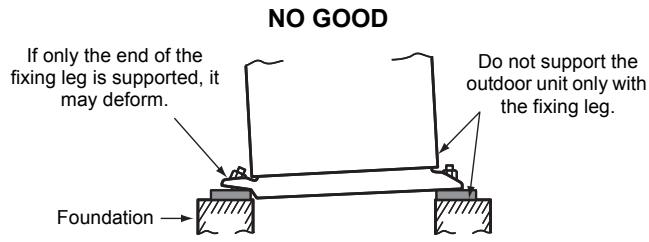
Set the out margin of the anchor bolt to 15 mm or less.
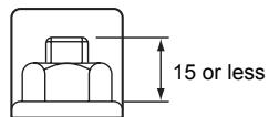
- When water is to be drained through the drain hose, attach the following drain nipple and waterproof rubber cap, and use the drain hose (Inner diam: 16 mm) sold on the market. Also seal knockout hole and the screws securely with silicone material, etc., to prevent water from leaking.
Some conditions may cause dewing or dripping of water.
- When collectively draining discharged water completely, use a drain pan.

Drain nipple
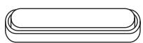
Waterproof rubber cap
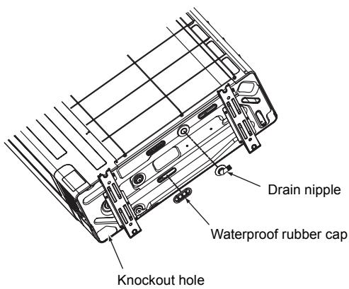
■ For Reference
If a heating operation is to be continuously performed for a long time under the condition that the outdoor temperature is 0 °C or lower, draining defrosted water may be difficult due to the bottom plate freezing, resulting in trouble with the cabinet or fan.
It is recommended to procure an anti-freeze heater locally in order to safely install the air to water heat pump.
For details, contact the dealer.
5 REFRIGERANT PIPING
■ Knockout of Pipe Cover
Knockout procedure
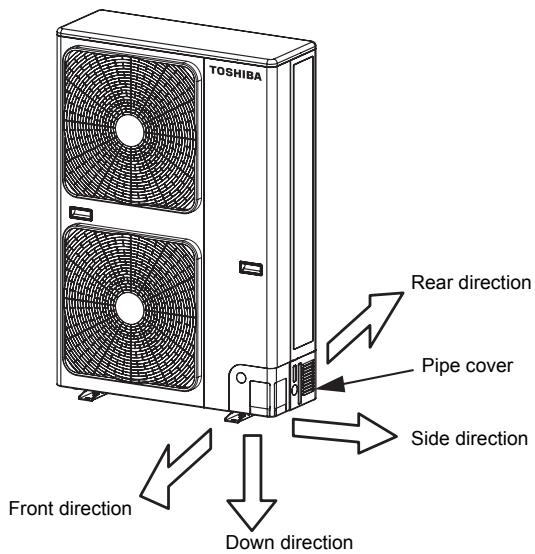
- The indoor/outdoor connecting pipes can be connected in 4 directions.
Take off the knockout part of the pipe cover through which pipes or wires will pass through the base plate. - Detach the pipe cover and tap on the knockout section a few times with the shank of a screwdriver. A knockout hole can easily be punched.
- After punching out the knockout hole, remove burrs from the hole and then install the supplied protective bush and guard material around the passage hole to protect wires and pipes.
Be sure to attach the pipe covers after pipes have been connected. Cut the slits under the pipe covers to facilitate the installation.
After connecting the pipes, be sure to mount the pipe cover. The pipe cover is easily mounted by cutting off the slit at the lower part of the pipe cover.
natural_image
Line drawing of hands using a tool to apply or install a device (no text or symbols present)* Be sure to wear heavy work gloves while working.
■ Optional Installation Parts (Locally procured)
| Parts name | Q'ty | |
| A | Refrigerant pipingLiquid side: ∅9.5 mmGas side: ∅15.9 mm | One each |
| B | Pipe insulating material(polyethylene foam, 10 mm thick) | 1 |
| C | Putty, PVC tape | One each |
■ Refrigerant Piping Connection

CAUTION
TAKE NOTE OF THESE 4 IMPORTANT POINTS BELOW FOR PIPING WORK
- Keep dust and moisture away from inside the connecting pipes.
- Tightly connect the connection between pipes and the unit.
- Evacuate the air in the connecting pipes using a VACUUM PUMP.
- Check for gas leaks at connection points.
Piping connection
| Liquid side | |
| Outer diameter | Thickness |
| ∅9.5 mm | 0.8 mm |
| Gas side | |
| Outer diameter | Thickness |
| 15.9 mm | 1.0 mm |
Flaring
- Cut the pipe with a pipe cutter.
Be sure to remove burrs that may cause a gas leak. - Insert a flare nut into the pipe, and then flare the pipe. Use the flare nuts supplied with the air to water heat pump or those for R410A.
Insert a flare nut into the pipe, and flare the pipe.
As the flaring sizes of R410A differ from those of refrigerant R22, the flare tools newly manufactured for R410A are recommended.
However, the conventional tools can be used by adjusting the projection margin of the copper pipe.
Projection margin in flaring: B (Unit: mm)
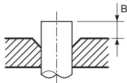
Rigid (Clutch type)
| Outer diam. of copper pipe | R410A tool used | Conventional tool used |
| R410A | 1.0 to 1.5 | |
| 9.5 | 0 to 0.5 | |
| 15.9 |
Flaring diameter size: A (Unit: mm)
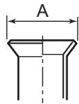
| Outer diam. of copper pipe | A_-0.4^+0 |
| 9.5 | 13.2 |
| 15.9 | 19.7 |
* In case of flaring for R410A with the conventional flare tool, pull the tool out approx. 0.5 mm more than that for R22 to adjust it to the specified flare size. The copper pipe gauge is useful for adjusting the projection margin size.
Piping necessary to change the flare nut/machining size due to pipe compression
▼ Flare nut width: H and flare matching size: A.
Flare nut width: H
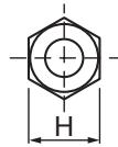
(mm)
| Copper pipe outer dia. | ∅6.4 | ∅9.5 | ∅12.7 | ∅15.9 | ∅19.0 |
| For R410A | 17 | 22 | 26 | 29 | 36 |
| For R22 | Same as above | 24 | 27 | Same as above | |
Flare machining size: A
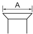
(mm)
| Copper pipe outer dia. | 6.4 | 9.5 | 12.7 | 15.9 | 19.0 |
| For R410A | 9.1 | 13.2 | 16.6 | 19.7 | 24.0 |
| For R22 | 9.0 | 13.0 | 16.2 | 19.4 | 23.3 |
Becomes a little larger for R410A
Do not apply refrigerator oil to the flare surface.
■ Tightening of Connecting Part
- Align the centers of the connecting pipes and fully tighten the flare nut with your fingers. Then fix the nut with a wrench as shown in the figure and tighten it with a torque wrench.
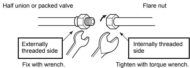
- As shown in the figure, be sure to use two wrenches to loosen or tighten the flare nut of the valve on the gas side. If you use a single crescent, the flare nut cannot be tightened to the required tightening torque.
On the other hand, use a single crescent to loosen or tighten the flare nut of the valve on the liquid side.
(Unit: N•m)
| Outer dia. of copper pipe | Tightening torque |
| 9.5 mm (diam.) | 33 to 42 (3.3 to 4.2 kgf•m) |
| 15.9 mm (diam.) | 68 to 82 (6.8 to 8.2 kgf•m) |
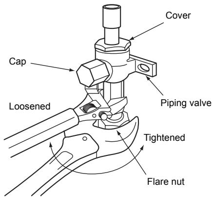
Valve at gas side

CAUTION
- Do not put the crescent wrench on the cap or cover.
The valve may break. - If applying excessive torque, the nut may break according to some installation conditions.
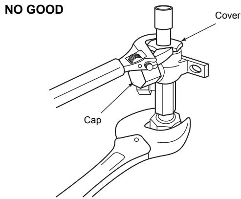
- After the installation work, be sure to check for gas leaks of the pipe connections with nitrogen.
- Pressure of R410A is higher than that of R22 (Approx. 1.6 times). Therefore, using a torque wrench, tighten the flare pipe connecting sections that connect the indoor/outdoor units at the specified tightening torque. Incomplete connections may cause not only a gas leak, but also trouble with the refrigeration cycle.
Do not apply refrigerating machine oil to the flared surface.
■ Refrigerant Pipe Length
Refrigeration pipe
H: max. ±30 m (above/below)
L: max. 30 m, min 5 m
30 m chargeless
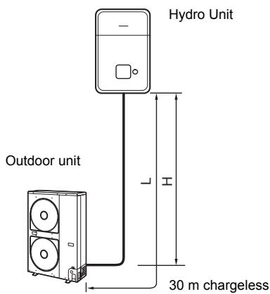
6 AIR PURGING
■ Airtight test
Before starting an airtight test, further tighten the spindle valves on the gas side and liquid side.
Pressurize the pipe with nitrogen gas charged from the service port to the design pressure (4.15 MPa) to conduct the airtight test.
After the airtight test is completed, evacuate the nitrogen gas.
Air Purge
With respect to the preservation of the terrestrial environment, adopt “Vacuum pump” to purge air (Evacuate air in the connecting pipes) when installing the unit.
- Do not discharge the refrigerant gas to the atmosphere to preserve the terrestrial environment.
- Use a vacuum pump to discharge the air (nitrogen, etc.) that remains in the set. If air remains, the capacity may decrease.
For the vacuum pump, be sure to use one with a backflow preventer so that the oil in the pump does not backflow into the pipe of the air to water heat pump when the pump stops.
(If oil in the vacuum pump is put in an air to water heat pump including R410A, it may cause trouble with the refrigeration cycle.)
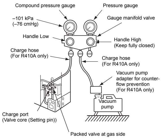
Vacuum pump
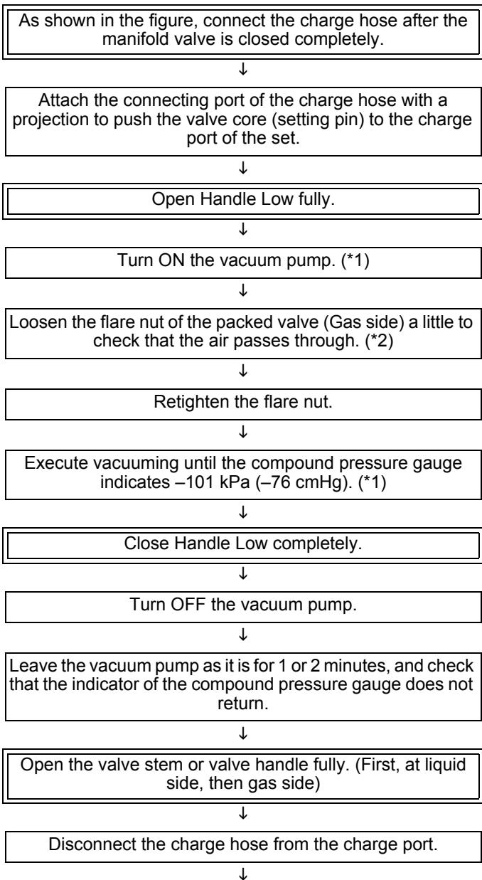
flowchart
graph TD
    A["As shown in the figure, connect the charge hose after the manifold valve is closed completely."] --> B["Attach the connecting port of the charge hose with a projection to push the valve core (setting pin) to the charge port of the set."]
    B --> C["Open Handle Low fully."]
    C --> D["Turn ON the vacuum pump. (*1)"]
    D --> E["Loosen the flare nut of the packed valve (Gas side) a little to check that the air passes through. (*2)"]
    E --> F["Retighten the flare nut."]
    F --> G["Execute vacuuming until the compound pressure gauge indicates -101 kPa (-76 cmHg). (*1)"]
    G --> H["Close Handle Low completely."]
    H --> I["Turn OFF the vacuum pump."]
    I --> J["Leave the vacuum pump as it is for 1 or 2 minutes, and check that the indicator of the compound pressure gauge does not return."]
    J --> K["Open the valve stem or valve handle fully. (First, at liquid side, then gas side)"]
    K --> L["Disconnect the charge hose from the charge port."]
Tighten the valve and caps of the charge port securely.
*1 Use the vacuum pump, vacuum pump adapter, and gauge manifold correctly referring to the manuals supplied with each tool before using them.
Check that the vacuum pump oil is filled up to the specified line of the oil gauge.
*2 When air is not charged, check again whether the connecting port of the discharge hose, which has a projection to push the valve core, is firmly connected to the charge port.
■ How to open the valve
Open or close the valve.
Liquid side
Open the valve with a 4 mm hexagon wrench.
Gas side
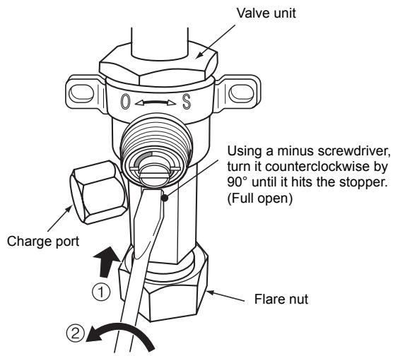
Handle position
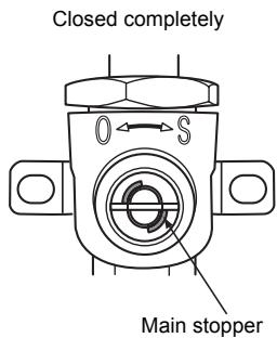
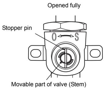
- While the valve is fully opened, after the screwdriver has reached the stopper, do not apply torque exceeding 5 N·m. Applying excessive torque may damage the valve.
Valve handling precautions
- Open the valve stem until it strikes the stopper. It is unnecessary to apply further force.
- Securely tighten the cap with a torque wrench.
Cap tightening torque
| Valve size | ∅9.5 mm | 33 to 42 N•m(3.3 to 4.2 kgf•m) |
| ∅15.9 mm | 20 to 25 N•m(2.0 to 2.5 kgf•m) | |
| Charge port | 14 to 18 N•m(1.4 to 1.8 kgf•m) | |
■ Replenishing refrigerant
This model is a 30 m chargeless type that does not need to have its refrigerant replenished for refrigerant pipes up to 30 m.
Refrigerant replenishing procedure
- After vacuuming the refrigerant pipe, close the valves and then charge the refrigerant while the air to water heat pump is not working.
- When the refrigerant cannot be charged to the specified amount, charge the required amount of refrigerant from the charge port of the valve on the gas side during cooling.
Requirement for replenishing refrigerant
Replenish liquid refrigerant.
When gaseous refrigerant is replenished, the refrigerant composition varies, which disables normal operation.
Adding additional refrigerant
- The refrigerant need not be reduced for a 30 meter (or less) refrigerant pipe.
7 ELECTRICAL WORK

WARNING
- Using the specified wires, ensure that the wires are connected, and fix wires securely so that the external tension to the wires does not affect the connecting part of the terminals.
Incomplete connection or fixation may cause a fire, etc.
- Be sure to connect the earth wire. (grounding work)
Incomplete grounding may lead to electric shock.
Do not connect ground wires to gas pipes, water pipes, lightning rods or ground wires for telephone wires.
- The appliance shall be installed in accordance with national wiring regulations.
Capacity shortages of the power circuit or an incomplete installation may cause an electric shock or fire.

CAUTION
- Wrong wiring may cause a burn-out of some electrical parts.
- Be sure to use the cord clamps attached to the product.
- Do not damage or scratch the conductive core or inner insulator of the power and inter-connecting wires when peeling them.
-
Use the power and Inter-connecting wires with specified thicknesses, specified types and protective devices required.
-
Remove the panel, and you can see electric parts on the front side.
- A metal pipe can be installed through the hole for wiring. If the hole size does not fit the wiring pipe to be used, drill the hole again to an appropriate size.
- Be sure to clamp the power wires and indoor/outdoor connecting wires with a banding band along the connecting pipe so that the wires do not touch the compressor or discharge pipe.
- (The compressor and the discharge pipe become hot.)
Ensure all wires are secured using the cord clamps on the pipe valve fixing plate located inside the unit
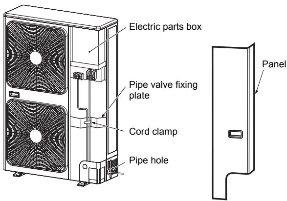
■ Wiring between Hydro Unit and Outdoor Unit
The dashed lines show on-site wiring.
Connect the indoor/outdoor connecting wires to the identical terminal numbers on the terminal block of each unit. Incorrect connection may cause a failure.
HWS-803H-E HWS-1103H-E HWS-1403H-E
Input power 220-230V \~,50Hz
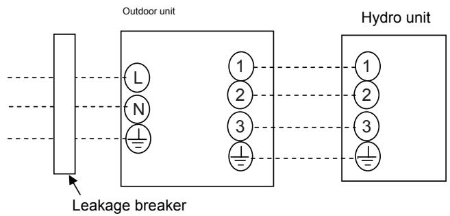
flowchart
graph LR
    A["Leakage breaker"] --> B["Outdoor unit"]
    B --> C["Hydro unit"]
    subgraph Outdoor unit
        L["L"]
        N["N"]
        E["⊕"]
    end
    subgraph Hydro unit
        1["1"]
        2["2"]
        3["3"]
        E["⊕"]
    end
    L --> E
    N --> E
    1 --> 2
    2 --> 3
    3 --> E
HWS-1103H8-E, H8R-E HWS-1403H8-E, H8R-E HWS-1603H8-E, H8R-E
Input power 380-400V 3N\~,50Hz
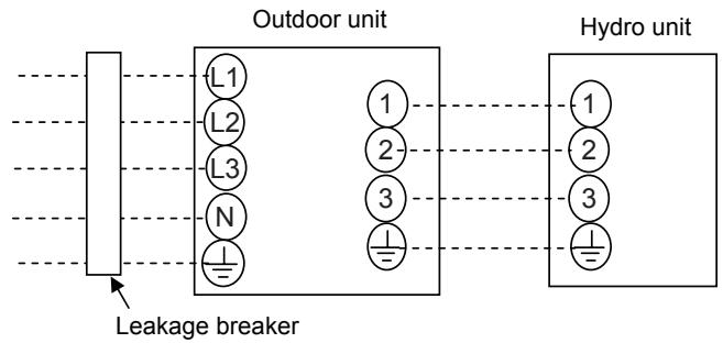
flowchart
graph LR
    A["Leakage breaker"] --> B["L1"]
    A --> C["L2"]
    A --> D["L3"]
    A --> E["N"]
    B --> F["1"]
    C --> G["2"]
    D --> H["3"]
    E --> I["4"]
    F --> J["Hydro unit"]
    G --> J
    H --> J
    I --> J
For the air to water heat pump, connect a power wire with the following specifications.
| Model HWS- | 803H-E | 1103H-E | 1403H-E | 1103H8-E1103H8R-E | 1403H8-E1403H8R-E | 1603H8-E1603H8R-E |
| Power supply | 220-230V ~50 Hz | 380-400V 3N~50 Hz | ||||
| Maximum running current | 19.2A | 22.8A | 14.6A | |||
| Recommended field fuse | 20A | 25A | 16A | |||
| Power supply wire* | 3 × 2.5 mm^2 or more(H07 RN-F or 60245 IEC 66) | 5 × 2.5 mm^2 or more(H07 RN-F or 60245 IEC 66) | ||||
| Hydro/outdoor connecting wires* | 4 × 1.5 mm^2 or more(H07 RN-F or 60245 IEC 66) | |||||
* Number of wire × wire size
How to wire
- Connect the connecting wire to the terminal as identified with their respective numbers on the terminal block of the Hydro and outdoor units. H07 RN-F or 60245 IEC 66 (1.5 mm ^2 or more)
- When connecting the connecting wire to the outdoor unit terminal, prevent water from coming into the outdoor unit.
- Insulate the unsheathed cords (conductors) with electrical insulation tape. Process them so that they do not touch any electrical or metal parts.
- For interconnecting wires, do not use a wire joined to another on the way.
Use wires long enough to cover the entire length.

CAUTION
- An installation fuse must be used for the power supply line of this air to water heat pump.
- Incorrect/incomplete wiring may lead to an electrical fire or smoke.
- Prepare a dedicated power supply for the air to water heat pump.
- This product can be connected to the mains power. Fixed wire connections:
A switch that disconnects all poles and has a contact separation of at least 3 mm must be incorporated in the fixed wiring.
▼ HWS-803H-E, HWS-1103H-E, HWS-1403H-E
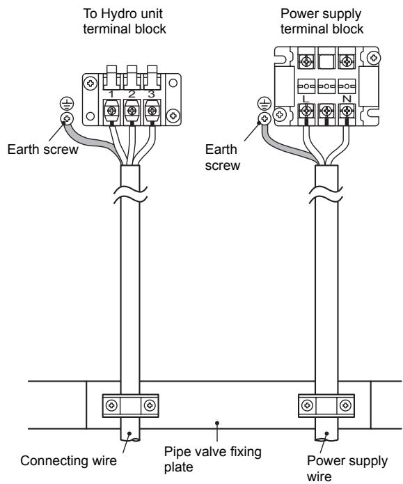
Stripping length power cord and connecting wire
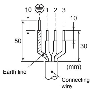
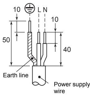
▼ HWS-1103H8-E, H8R-E
HWS-1403H8-E, H8R-E
HWS-1603H8-E, H8R-E

Stripping length power cord and connecting wire
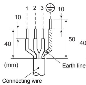
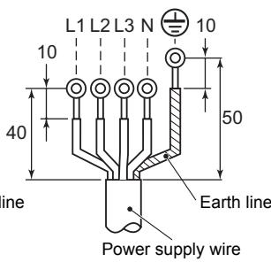

WARNING
Be sure to attach the provided clamp filter to the power supply wire in order to conform to EMC standards.
8 EARTHING
Connect the earth line properly following applicable technical standards.
Connecting the earth line is essential to preventing electric shock and to reducing noise and electrical charges on the outdoor unit surface due to the high-frequency wave generated by the frequency converter (inverter) in the outdoor unit.
If you touch the charged outdoor unit without an earth line, you may experience an electric shock.
9 FINISHING
After the refrigerant pipe, Hydro/Outdoor connecting wires have been connected, cover them with finishing tape and clamp them to the wall with off-the-shelf support brackets or their equivalent.
Keep the power wires and Hydro/outdoor connecting wires off the valve on the gas side or pipes that have no heat insulator.
10TEST RUN
- Turn on the leakage breaker at least 12 hours before starting a test run to protect the compressor during startup.
-
Check the following before starting a test run:
-
That all pipes are connected securely without leaks.
• That the valve is open.
If the compressor is operated with the valve closed, the outdoor unit will become overpressurized, which may damage the compressor or other components.
If there is a leak at a connection, air can be sucked in and the internal pressure further increases, which may cause a burst or injury.
- Operate the air to water heat pump in the correct procedure as specified in the Owner's Manual.
Please refer to the Hydro unit installation manual for the detail of the test run.
- For an air to water heat pump system that is operated on a regular basis, cleaning and maintenance of the Hydro/outdoor units are strongly recommended.
As a general rule, if an Hydro unit is operated for about 8 hours daily, the Hydro/outdoor units will need to be cleaned at least once every 3 months. This cleaning and maintenance should be carried out by a qualified service person.
Failure to clean the Hydro/outdoor units regularly will result in poor performance, icing, water leaking and even compressor failure.
12 AIR TO WATER HEAT PUMP OPERATING CONDITIONS
For proper performance, operate the air to water heat pump under the following temperature conditions:
| Cooling operation | 10°C to 43°C |
| Heating operation | -20°C to 25°C |
| Hot water operation | -20°C to 43°C |
If air to water heat pump is used outside of the above conditions, safety protection may work.
13 FUNCTIONS TO BE IMPLEMENTED LOCALLY
■ Handling Existing Pipe
When using the existing pipe, carefully check for the following:
• Wall thickness (within the specified range)
- Scratches and dents
• Water, oil, dirt, or dust in the pipe
- Flare looseness and leakage from welds
• Deterioration of copper pipe and heat insulator
Cautions for using existing pipe
- Do not reuse a flare nut to prevent gas leaks. Replace it with the supplied flare nut and then process it to a flare.
- Blow nitrogen gas or use an appropriate means to keep the inside of the pipe clean. If discolored oil or much residue is discharged, wash the pipe.
- Check welds, if any, on the pipe for gas leaks.
When the pipe corresponds to any of the following, do not use it. Install a new pipe instead.
- The pipe has been opened (disconnected from Hydro unit or outdoor unit) for a long period.
- The pipe has been connected to an outdoor unit that does not use refrigerant R22, R410A or R407C.
- The existing pipe must have a wall thickness equal to or larger than the following thicknesses.
| Reference outside diameter (mm) | Wall thickness (mm) |
| ∅9.5 | 0.8 |
| ∅15.9 | 1.0 |
| ∅19.0 | 1.0 |
- Do not use any pipe with a wall thickness less than these thicknesses due to insufficient pressure capacity.
■ Recovering Refrigerant
- Use refrigerant recovery switch SW801 on the P.C. board of the outdoor unit to recover refrigerant when the Hydro or outdoor unit is moved.
- Before recovering the refrigerant in the existing system, perform a cooling operation for at least 30 minutes.
Procedure
- Drain off the water in the Hydro unit.
- Turn on the power of the air to water heat pump.
- Set SW804 on the P.C. board of the outdoor unit to all OFF, and then press SW801 for 1 second or more. The air to water heat pump enters the forced cooling mode for up to 10 minutes. Operate or handle the valve to recover refrigerant during this time period.
- Upon completion of refrigerant recovery, close the valve and press SW801 for at least 1 second to stop operation.
- Turn off the power.
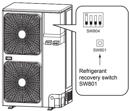

DANGER
Be careful of electric shock because the P.C. board has an electrical current running through it.
14 TROUBLESHOOTING
You can perform fault diagnosis of the outdoor unit with the LEDs on the P.C. board of the outdoor unit in addition to using the check codes displayed on the wired remote controller of the indoor unit.
Use the LEDs and check codes for various checks. Details of the check codes displayed on the wired remote controller of the indoor unit are described in the Installation Manual of the Hydro unit.
Verifying current abnormal status
- Check that DIP switch SW803 is set to OFF.
- Jot down the states of LED800 to LED804. (Display mode 1)
- Press SW800 for at least 1 second. The LED status changes to display mode 2.
- Check the code whose display mode 1 equals the LED states jotted down and display mode 2 equals the current flashing status of LED800 to LED804 from the following table to identify the cause.
Verifying an abnormal state in the past although the abnormal state no longer occurs
- Set bit 1 of DIP switch SW803 to ON.
- Jot down the states of LED800 to LED804. (Display mode 1)
- Press SW800 for at least 1 second. The LED status changes to display mode 2.
- Find an error whose display mode 1 equals the LED states jotted down and display mode 2 equals the current flashing states of LED800 to LED804 from the following table to identify the error.
- An outside air temperature (TO) sensor error can be checked only while it occurs.
(●: OFF ○: ON ◎: Flashing)
* The LEDs and DIP switches are located on the lower left of the P.C. board of the outdoor unit.
| No. | Cause | Display mode 1 | Display mode 2 | ||||||||
| D800 | D801 | D802 | D803 | D804 | D800 | D801 | D802 | D803 | D804 | ||
| 1 | Normal | ● | ● | ● | ● | ● | ● | ● | ● | ● | ● |
| 2 | Discharge (TD) sensor error | ○ | ○ | ● | ● | ○ | ● | ● | ◎ | ● | ● |
| 3 | Heat exchanger (TE) sensor error | ○ | ○ | ● | ● | ○ | ● | ◎ | ◎ | ● | ● |
| 4 | Heat exchanger (TL) sensor error | ○ | ○ | ● | ● | ○ | ◎ | ◎ | ◎ | ● | ● |
| 5 | Outside air temperature (TO) sensor error | ○ | ○ | ● | ● | ○ | ● | ● | ● | ◎ | ● |
| 6 | Suction (TS) sensor error | ○ | ○ | ● | ● | ○ | ● | ● | ◎ | ◎ | ● |
| 7 | Heat sink (TH) sensor error | ○ | ○ | ● | ● | ○ | ◎ | ● | ◎ | ◎ | ● |
| 8 | Outdoor temperature sensor (TE/TS) connection error | ○ | ○ | ● | ● | ○ | ◎ | ◎ | ◎ | ◎ | ● |
| 9 | Outdoor EEPROM error | ○ | ○ | ● | ● | ○ | ◎ | ◎ | ◎ | ◎ | ◎ |
| 10 | Compressor breakdown | ● | ● | ○ | ● | ○ | ◎ | ● | ● | ● | ● |
| 11 | Compressor lock | ● | ● | ○ | ● | ○ | ● | ◎ | ● | ● | ● |
| 12 | Current detection circuit error | ● | ● | ○ | ● | ○ | ◎ | ◎ | ● | ● | ● |
| 13 | Thermostat for compressor activated | ● | ● | ○ | ● | ○ | ● | ● | ◎ | ● | ● |
| 14 | Model data not set (on the service P.C. board) | ● | ○ | ○ | ● | ○ | ● | ◎ | ● | ◎ | ● |
| 15 | MCU-MCU communication error | ● | ○ | ○ | ● | ○ | ◎ | ● | ◎ | ◎ | ◎ |
| 16 | Discharge temperature error | ○ | ○ | ○ | ● | ○ | ◎ | ◎ | ● | ● | ● |
| 17 | Abnormal power (open phase detected or abnormal voltage) | ○ | ○ | ○ | ● | ○ | ◎ | ● | ◎ | ● | ● |
| 18 | Heat sink overheat | ○ | ○ | ○ | ● | ○ | ◎ | ◎ | ◎ | ● | ● |
| 19 | Gas leak detected | ○ | ○ | ○ | ● | ○ | ◎ | ◎ | ◎ | ◎ | ● |
| 20 | 4-way valve reverse error | ○ | ○ | ○ | ● | ○ | ◎ | ◎ | ● | ● | ◎ |
| 21 | High pressure release operation | ○ | ○ | ○ | ● | ○ | ● | ● | ◎ | ● | ◎ |
| 22 | Outdoor fan motor error | ○ | ○ | ○ | ● | ○ | ● | ◎ | ◎ | ● | ◎ |
| 23 | Compressor driver short-circuit protection | ○ | ○ | ○ | ● | ○ | ● | ◎ | ● | ◎ | ◎ |
| 24 | Position detection circuit error in one-line display | ○ | ○ | ○ | ● | ○ | ◎ | ● | ◎ | ◎ | ◎ |
| 25 | High pressure SW error | ○ | ○ | ○ | ● | ○ | ● | ● | ◎ | ● | ● |
▼ HWS-803H-E, HWS-1103H-E, HWS-1403H-E
* The LEDs and DIP switches are located at the lower left of the P.C. board of the outdoor unit.
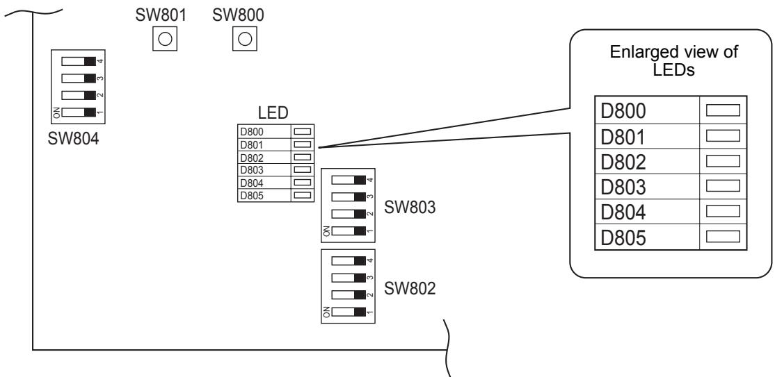
▼ HWS-1103H8-E, H8R-E
HWS-1403H8-E, H8R-E
HWS-1603H8-E, H8R-E
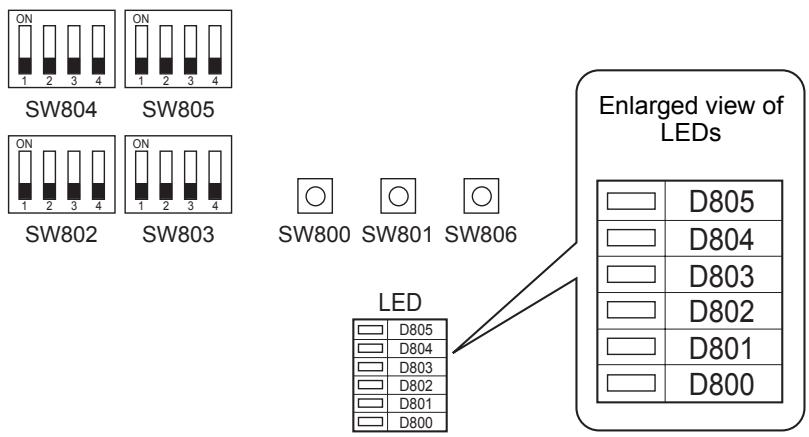
15APPENDIX
■ Work instructions
The existing R22 and R407C piping can be reused for our digital inverter R410A product installations.

WARNING
Confirming the existence of scratches or dents on the existing pipes and confirming the reliability of the pipe strength are conventionally referred to the local site. If the specified conditions can be cleared, it is possible to update existing R22 and R407C pipes to those for R410A models.
Basic conditions needed to reuse existing pipes
Check and observe the presence of three conditions in the refrigerant piping works.
- Dry (There is no moisture inside of the pipes.)
- Clean (There is no dust inside of the pipes.)
- Tight (There are no refrigerant leaks.)
Restrictions for use of existing pipes
In the following cases, the existing pipes should not be reused as they are. Clean the existing pipes or exchange them with new pipes.
- When a scratch or dent is heavy, be sure to use new pipes for the refrigerant piping works.
- When the existing pipe thickness is thinner than the specified "Pipe diameter and thickness," be sure to use new pipes for the refrigerant piping works.
- The operating pressure of R410A is high (1.6 times that of R22 and R407C). If there is a scratch or dent on the pipe or a thinner pipe is used, the pressure strength may be inadequate, which may cause the pipe to break in the worst case.
* Pipe diameter and thickness (mm)
| Pipe outer diameter | ∅6.4 | ∅9.5 | ∅12.7 | ∅15.9 | ∅19.0 | |
| Thickness | R410A | 0.8 | 0.8 | 0.8 | 1.0 | 1.0 |
- In case the pipe diameter is ∅12.7 mm or less and the thickness is 0.8 mm, be sure to use new pipes for the refrigerant piping works.
- When the outdoor unit was left with the pipes disconnected, or the gas leaked from the pipes and the pipes were not repaired and refilled.
- There is the possibility of rain water or air, including moisture, entering the pipe.
- When refrigerant cannot be recovered using a refrigerant recovery unit.
- There is the possibility that a large quantity of dirty oil or moisture remains inside the pipes.
- When a commercially available dryer is attached to the existing pipes.
- There is the possibility that copper green rust has been generated.
- When the existing air to water heat pump is removed after refrigerant has been recovered.
Check if the oil is judged to be clearly different from normal oil.
- The refrigerator oil is copper rust green in color: There is the possibility that moisture has mixed with the oil and rust has been generated inside the pipe.
- There is discolored oil, a large quantity of residue, or a bad smell.
-
A large quantity of shiny metal dust or other wear residue can be seen in the refrigerant oil.
-
When the air to water heat pump has a history of the compressor failing and being replaced.
- When discolored oil, a large quantity of residue, shiny metal dust, or other wear residue or mixture of foreign matter is observed, trouble will occur.
- When temporary installation and removal of the air to water heat pump are repeated such as when leased etc.
- If the type of refrigerator oil of the existing air to water heat pump is other than the following oil (Mineral oil), Suniso, Freol-S, MS (Synthetic oil), alkyl benzene (HAB, Barrel-freeze), ester series, PVE only of ether series.
- The winding-insulation of the compressor may deteriorate.
NOTE
The above descriptions are results have been confirmed by our company and represent our views on our air to water heat pump, but do not guarantee the use of the existing pipes of air to water heat pump that have adopted R410A in other companies.
Curing of pipes
When removing and opening the Hydro or outdoor unit for a long time, cure the pipes as follows:
- Otherwise rust may be generated when moisture or foreign matter due to condensation enters the pipes.
- The rust cannot be removed by cleaning, and new pipes are necessary.
| Placement location | Term | Curing manner |
| Outdoors | 1 month or more | Pinching |
| Less than 1 month | Pinching or taping | |
| Hydro | Every time |
| This product contains fluorinated greenhouse gases covered by the Kyoto Protocol | |
| Chemical Name of Gas | R410A |
| Global Warming Potential (GWP) of Gas | 1 975 |

CAUTION
- Paste the enclosed refrigerant label adjacent to the charging and/or recovering location.
- Clearly write the charged refrigerant quantity on the refrigerant label using indelible ink. Then, place the included transparent protective sheet over the label to prevent the writing from rubbing off.
- Prevent emission of the contained fluorinated greenhouse gas. Ensure that the fluorinated greenhouse gas is never vented to the atmosphere during installation, service or disposal. When any leakage of the contained fluorinated greenhouse gas is detected, the leak shall be stopped and repaired as soon as possible.
- Only qualified service personnel are allowed to access and service this product.
- Any handling of the fluorinated greenhouse gas in this product, such as when moving the product or recharging the gas, shall comply under (EC) Regulation No. 842/2006 on certain fluorinated greenhouse gases and any relevant local legislation.
- Periodical inspections for refrigerant leaks may be required depending on European or local legislation.
- Contact dealers, installers, etc., for any questions.
natural_image
Symbol of a trash bin crossed out by diagonal lines, representing no waste or discharge (no text or labels)CE
IMPORTANT INFORMATION AND WARNING:
READ BEFORE INSTALLING THE UNIT. KEEP IN A SAFE PLACE. THE INFORMATION IN THIS BOOKLET IS NEEDED FOR END OF LIFE, DISPOSAL OR REUSE OF THE UNIT.
• We are very sensitive to environment and welcome the 2002/96/EC Directive WEEE (Waste Electrical and Electronic Equipment).
- This product is compliant with EU directive 2002/96/EC. It must be collected separately after its use is completed, and cannot be disposed of as unsorted municipal waste.
- The objectives of EU directive 2002/96/EC are to tackle the fast increasing waste stream of electrical and electronic equipment, increase recycling of electric & electronic equipment ("EEE"), and to limit the total quantity of waste EEE ("WEEE") going to final disposal.
- The crossed-out wheeled bin symbol 📋 that is affixed to the product means that this product falls under the Directive.
- The user is responsible for returning the product to the appropriate collection facility, as specified by your municipality or the distributor. In case of a new product installation, it may be possible to have the distributor pick up old WEEE directly.
- The producer, importer and distributor of the product are responsible for collection and treatment of waste, either directly or through a collective system.
The list of our distributor in each country is shown below.
• In case of a violation of the Directive, sanctions are set in each country.
- We are in general following the "CECED interpretation," and consider the WEEE applicable to Portable units, Dehumidifiers, WRACs (Window Room air to water heat pumps), Split Systems up to 12 kW, plug in refrigerators and freezers.
- Nevertheless, there may be differences among member state laws. In case country laws exclude some products from WEEE scope, country law must be followed, and WEEE obligations do not have to be followed for products that fall out of country low scope.
- This directive does not apply to products sold outside European Community. In case the product is sold outside the EU, WEEE obligations do not have to be followed, while compliance with local regulations must be ensured.
- For additional information, please contact the municipal facility, the shop/dealer/installer that sold the product, or the producer.
① Country
② Name of Company responsible for WEEE.
| 1 | 2 |
| Austria | AIRCOND, Klimaanlagen Handelsgesellschaft m.b.H Petesgasse 45, A-8010 Graz Austria |
| Belgium | DOLPHIN NV, Fotografi elaan 12, B-2610, Antwerpen Belgium |
| Cyprus | Carrier Hellas Airconditioning S.A.- 4g Andersen street-11525 Athens, Greece |
| Denmark | GIDEX A/S, Korshoj 10, 3600 Frederikssund, Denmark |
| Estonia | Carrier OY Linnavuorentie 28A 00950 Helsinki, Finland |
| Finland | Carrier OY Linnavuorentie 28A 00950 Helsinki, Finland |
| France | Carrier S.A. Route de Thil BP 49 01122 Montiuel Cedex France |
| Germany | Carrier GmbH & Co. KG Edisonstrasse 2 85716 Unterschleissheim |
| Greece | Carrier Hellas Airconditioning S.A.- 4g Andersen street-11525 Athens, Greece |
| Holland | INTERCOOL Technics BV Nikkelstraat 39, Postbus 76 2980 AB Ridderkerk Netherlands |
| 1 | 2 |
| Ireland | GT Phelan Unit 30 Southern Cross Business Park Bray Co Wicklow, Ireland |
| Italy | Carrier SpA Via R. Sanzio, 9 20058 Villasanta (Milano), Italy |
| Latvia | Carrier OY Linnavuorentie 28A 00950 Helsinki, Finland |
| Lithuania | Carrier OY Linnavuorenlie 28A 00950 Helsinki, Finland |
| Luxembourg | DOLPHIN NV Fotografi elaan 12, B-2610, Antwerpen Belgium |
| Malta | CUTRICO Services Ltd, Cutrico Building Psala Street, Sta Venea HMR 16, Malta |
| Norway | Carrier AB - P.O.BOX 8946-Arods Industrivag 32. S-402 73 Gothenburg, Sweden |
| Poland | Carrier Polska Sp. Z.o.o. Postepu 14 02-676 Warsaw Poland |
| Portugal | Carrier Portugal - AR Condicionado LDA Avenida do Forte, Nr. 3 Editi cio Suecia I,Piso 1 Camaxide 2794-043 Portugal |
| 1 | 2 |
| UK | Toshiba Carrier UK Ltd Porsham Close, Belliver Ind. Est. Plymouth, Devon, PL6 7DB |
| Czech Republic | AIRCOND, , Klimaanlagen Handelsgesellschaft m.b.H Petersgasse 45, A-8010 Graz Austria |
| Slovakia | AIRCOND, , Klimaanlagen Handelsgesellschaft m.b.H Petersgasse 45, A-8010 Graz Austria |
| Slovenia | AIRCOND, , Klimaanlagen Handelsgesellschaft m.b.H, Petersgasse 45, A-8010 Graz Austria |
| Spain | Carrier Espana S.L. - Paseo Castellana 36-38, 28046 Madrid |
| Sweden | Carrier AB - P.O.BOX 8946-Arods Industrivag 32 . S-402 73 Gothenburg |
| Hungary | AIRCOND, Klimaanlagen Handelsgesellschaft m.b.H Petersgasse 45, A-8010 Graz Austria |
The manufacturer reserves the right to change any product specifications without notice.
MEMO
9. OWNER'S MANUAL
Hydro Unit
Model name:
HWS-803XWHM3-E
HWS-803XWHT6-E
HWS-803XWHD6-E
HWS-803XWHT9-E
HWS-1403XWHM3-E
HWS-1403XWHT6-E
HWS-1403XWHD6-E
HWS-1403XWHT9-E

natural_image
Simple line drawing of a rectangular door with a square and circular button on the side (no text or symbols)Thank you very much for purchasing TOSHIBA Air to Water Heat Pump.
Please read this owner's manual carefully before using the system.
- Be sure to obtain the “Owner’s manual” and “Installation manual” from constructor (or dealer).
Request to constructor or dealer
- Please clearly explain the contents of the Owner's manual before handing it over to the Customer.
ADOPTION OF NEW REFRIGERANT
This Air to Water Heat Pump is a new type which adopts a new refrigerant HFC (R410A) instead of the conventional refrigerant R22 in order to prevent destruction of the ozone layer.
Contents
1 SAFETY PRECAUTIONS....165
2 NAMES AND FUNCTIONS OF PARTS 167
3 HOW TO USE FUNCTIONS .... 170
4 USER MAINTENANCE....175
5 AIR TO WATER HEAT PUMP OPERATIONS AND PERFORMANCE ..... 175
6 TROUBLESHOOTING 177
1 SAFETY PRECAUTIONS

DANGER
• DO NOT ATTEMPT TO INSTALL THIS UNIT YOURSELF.
• THIS UNIT REQUIRES A QUALIFIED INSTALLER.
• DO NOT ATTEMPT TO REPAIR THE UNIT YOURSELF.
• THIS UNIT HAS NO COMPONENTS WHICH YOU CAN REPAIR.
• OPENING OR REMOVING THE COVER WILL EXPOSE YOU TO DANGEROUS VOLTAGES.
• TURNING OFF THE POWER SUPPLY WILL PREVENT POTENTIAL ELECTRIC SHOCK.

WARNING
INSTALLATION WARNINGS
- Be sure to ask a dealer or a store specialized in electrical work to install the Air to Water Heat Pump.
- The Air to Water Heat Pump should be installed by a suitably qualified installer, if not; this may lead to problems such as water leaks, electric shock, fire, etc.
- Ensure the correct grounding procedures are applied when installing the Air to Water Heat Pump.
- Do not connect the ground wire to gas pipes, water pipes, lightning rods or telephone ground wires.
- Should the Air to Water Heat Pump be improperly grounded, this could lead to an electric shock.
- Serious damage can occur if there is water leak. Therefore, the Hydro Unit is recommended to be installed in a room with waterproof flooring and drainage systems.
- Products and parts to be used in combination with this product must be specified products and parts that meet prescribed specifications. If unspecified products or parts are used, a failure, smoke, fire, or electric shock may be caused.
OPERATION WARNINGS
- Avoid injury or damage to the outdoor unit by never inserting fingers or sticks into the air outlet or air inlet of the outdoor unit, during operation the fans run at a high speed.
- Should you notice something unusual with the Air to Water Heat Pump (such as a burning smell or weak heating power), immediately turn off the main switch and circuit breaker from the main power supply to stop the Air to Water Heat Pump, and contact the dealer.
- If there is a suspected problem with the operation of the Air to Water Heat Pump, continuous operation is not recommended, operational failures may lead to machine breakdown, electric shock, a fire, etc.
- Do not spill water or other liquid onto the Hydro Unit.
- If the unit is wet, it could cause an electric shock.
WARNINGS AT MOVEMENT AND REPAIR
- Do not attempt to move or repair the unit yourself.
- Due to the presence of high voltage, removal of any covers may result in an electric shock.
- Should there be any requirements for the Air to Water Heat Pump to be moved, always consult the dealer or qualified installer.
- Should the Air to Water Heat Pump be improperly installed, it may lead to electric shock or fire.
- Whenever the Air to Water Heat Pump requires repair, request assistance from the dealer.
- Should the Air to Water Heat Pump be improperly repaired, the result may lead to electric shock or fire.

CAUTION
This appliance is not intended for use by person (including children) with reduced physical sensory or mental capabilities, or lack of experience and knowledge, unless they have been given supervision or instruction concerning use of the appliance by a person responsible for their safety.
TO DISCONNECT THE APPLIANCE FROM THE MAIN POWER SUPPLY
This appliance must be connected to the main power supply using a circuit breaker or switch with a contact separation of at least 3 mm.
INSTALLATION CAUTIONS
- Be sure to connect the Air to Water Heat Pump to a dedicated power supply using the rated voltage. Failure to do so may cause the unit to break down or cause a fire.
- Do not install the unit in a place where there is a risk that flammable gas may leak.
- An accumulation of flammable gases around the unit may result in a fire.
OPERATION CAUTIONS
- To ensure satisfactory performance, please read this manual carefully before operating the Air to Water Heat Pump system.
- Do not install the Air to Water Heat Pump in special-purpose rooms such as a ship or any kind of vehicle.
Doing so could harm machine performance. - When the Air to Water Heat Pump is operated together with a combustion device in the same place, pay careful attention to ventilation and let fresh air into the room.
Poor ventilation can cause an oxygen shortage. - When the Air to Water Heat Pump is used in a closed room, pay careful attention to the ventilation of the room. Poor ventilation can cause an oxygen shortage.
- Do not put a container with water, such as a vase, on the unit, should water enter the unit the result may lead to an electric shock, this would be due to deterioration in the electric insulation.
- Perform occasional checks to the concrete supports underneath the outdoor unit. If the base is left damaged or deteriorated, the unit may topple over which could result in possible injury.
- Check from time to time that the unit mounts are not damaged. If the mounts are left damaged, the unit may drop or topple over, resulting in possible injury.
- Do not wash the unit with water. This could cause an electric shock.
- Do not use alcohol, benzene, thinner, glass cleaner, polishing powder, or other solvent for cleaning the unit because they can deteriorate and damage the Air to Water Heat Pump.
- Before cleaning the unit, be sure to turn off the main switch or circuit breaker.
- Do not place anything, or step, on the unit, this could cause the unit to fall or topple over which may result in possible injury.
- To achieve maximum performance, the Air to Water Heat Pump must operate within the temperature range specified in the instructions.
Failure to do so may cause malfunction, break down, or water to leak from the unit. - Clear away snow before it accumulates on the outdoor unit.
Accumulated snow can lead to malfunction and damage. - Do not locate other electric appliances or furniture underneath the unit.
Water may drip from the unit, which could lead to rust, unit failure and damage to property. - Do not allow the obstruction of air flow around the outdoor unit; place any items within the specified installation service space requirements.
Obstructed air flow can lower performance and cause damage. - Check for water leaks. In communal housing, leaking water may damage lower floors.
Check for water leaks everyday. - Do not touch the water pipes, refrigerant pipes, or joints. These may become extremely hot.
Do not drink water produced by the Air to Water Heat Pump. - After extended use, fresh water may become contaminated by the Hydro Unit, due to deterioration of pipe materials, etc.
- If fresh water contains solid matter, is discolored, turbid or smells, DO NOT DRINK IT.
- Call for equipment inspection immediately.
- Use source water that satisfies water quality standard.
- When the unit will not be used for a long period of time, ask your dealer or a qualified service shop to drain the water inside the Hydro Unit in order to prevent the water quality from changing.
- When restarting use, ask your dealer or a qualified service shop to charge the unit with water and perform a trial operation.
- Ask your dealer or a qualified service shop to periodically clean the strainer.
- Ask your dealer or a qualified service shop to confirm that the relief valve is operating correctly.
- Do not hit the manometer, because it is made of glass. It is breakable.
2 NAMES AND FUNCTIONS OF PARTS
■ Buttons
▼ Fig. 2-01
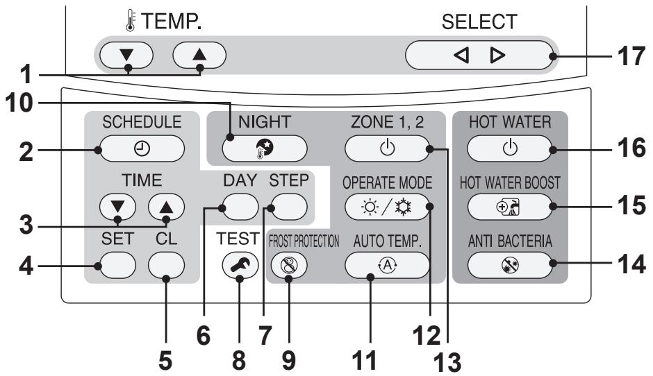
flowchart
graph TD
    A["TEMP."] --> B["SCHEDULE"]
    B --> C["TIME"]
    C --> D["SET CL"]
    D --> E["6"]
    E --> F["8"]
    F --> G["7"]
    G --> H["9"]
    H --> I["11"]
    I --> J["12"]
    J --> K["13"]
    K --> L["14"]
    L --> M["15"]
    M --> N["HOT WATER BOOST"]
    N --> O["16"]
    O --> P["17"]
    P --> Q["SELECT"]
1. TEMP. button: | Changes the set temperature for each operation mode (ZONE1/2 hot water) by 1°C step. |
2. SCHEDULE button: | Sets the current time and scheduled weekly operation. |
3. TIME button: | Changes time for current time setting and scheduled weekly operation setting with ▼ and▲ buttons. |
4. SET button: | Determines the entered current time setting and scheduled weekly operation setting. |
5. CL button: | Clears settings for the current time and scheduled weekly operation. Cancels audible alarm in the event of a system fault. |
6. DAY button: | Sets days of the week for current time setting and scheduled weekly operation setting. |
7. STEP button: | Specifies switching STEP number in a day for weekly schedule. |
8. TEST button: | Used for test run or service. |
9. FROST PROTECTION button: | Controls minimum operation for unused period (going out, absence, etc.) for anti freezing. |
10. NIGHT button: | Controls the night set back operation. |
11. AUTO TEMP. button:  | Switches setting temperature automatically according to outside temperature. (Pressing this button long changes the mode to data setting mode.) |
12. OPERATE MODE button:  | Selects ZONE1/2 operation mode (heating or cooling). |
13. ZONE1, 2 button:  | Turns on/off the zone (floor heating/radiator/Fan Coil Unit) operation. |
14. ANTI BACTERIA button:  | Regularly increases the hot water temperature in the tank for sterilization. (Pressing this button long changes the mode to data setting mode.) |
15. HOT WATER BOOST button:  | Boosts boiling when high tapping temperature is required temporarily. |
16. HOT WATER button:  | Turns on/off hot water operation. |
17. SELECT button:  | Selects an operation mode when changing the set temperature of each operation mode. |
NOTE
Some functions are not provided depending on the system specifications in use.
For details, contact the installation company.
■ Meaning of Indication
▼ Fig. 2-02
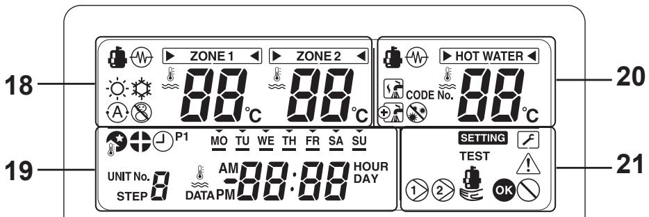
| Heating side [ZONE1, 2] | Hot water side | ||
| 18. Indication | Description | 20. Indication | Description |
| ZONE 1 | Lights when floor heater or radiator is connected (when the system has floor heater or radiator). | HOT WATER | Lights when hot water supply system is connected (when the system has hot water supply). |
| ZONE 2 | Lights when controlling the second temperature.(It may not light depending on the system) | ||
| The [▶◀] mark lights for operation mode for which temperature is to be changed. | |||
 | Lights during heating or cooling operation using the heat pump. | [4ZWY] | Lights when hot water supply operation is performed by heat pump. |
 | Lights when the electric heater, inside the hydro unit, is energised during a heating operation. |  | Lights when the electric cylinder heater is energised during hot water operation. |
| [BCW8] | Lights when heating is selected. |  | Lights during hot water supply operation. |
 | Lights when cooling is selected. |  | Lights while hot water boost is activated. |
| [BOKA] | Lights when the FROST PROTECTION button is pressed and goes out when the button is pressed again. |  | Lights when the ANTI BACTERIA button is pressed and goes out when the button is pressed again. |
| [BSAK] | Lights when Auto operation is selected. | ||
| [YCS4] | Displays heating/cooling set temperature.(Heating: 20 to 55°C, factory setting: Auto, cooling: 10 to 30°C)Goes out when Auto operation is selected.When room temperature control is selected with optional second remote control, it displays set room temperature.* |  | Displays hot water set temperature.(40 to 75°C, factory setting: 65°C) |
| °C | Lights when the set temperature or sensor's water temperature is displayed with the 7-segment indicator. | ||
* Ask your installer about room temperature control setting.
| 19. Indication | Description |
 | Clock: Displays the current time (AM or PM). |
 | Displays days of the week (Sunday to Saturday). |
 | Lights when the NIGHT button is pressed and goes out when the button is pressed again. |
 | Lights when nighttime quiet operation is set. |
| P1 | Indicates scheduled operation 1 status (including setting time). |
 | Displays the scheduled operation step when the scheduled operation STEP1-5 program is set. |
 | Lights during time setting and scheduled operation setting. |
| 21. Indication | Description |
 | Lights while internal pump (pump 1) or expansion pump (pump 2) is driven. |
 | Lights when the auxiliary boiler or external booster heater supports the heat pump operation. |
 | Lights when the unit enters the data set mode and goes out when the unit exits the data set mode. |
 | Lights when the unit enters the service mode and goes out when the unit exits the service mode. |
 | Lights when an error occurs and goes out when the error is cleared. |
 | Lights for two seconds when settings are completed. |
 | Lights for two seconds when settings failed. |
3 HOW TO USE FUNCTIONS
■ Timer setting
Function not available on second remote controller
First, set the current time on the remote controller.
Procedure to set the current time and day of the week (If day/time is not set, the indication of time and day of the week blinks.)
(1) Press the TIME ▲ or ▼ button for 4 seconds or more to enable the time setting mode.
- The SETTING SETTING segment blinks.
(2) Set the current day of the week with the DAY ○ button.
- Each time the button is pressed, the ▼ segment shifts cyclically pointing MO → TU →...→ SU → MO.
(3) Set the current time with the TIME ▲ and ▼ buttons.
- If you press the buttons long, the current time can be set in units of 10 minutes.
(4) Press the SET ○ button to determine the setting.
■ Heating or cooling operation
Performing heating or cooling operation
- Press the ZONE1, 2 ⏻ button to start heating or cooling operation.
The set temperature appears under ☐ ZONE 1 on the remote controller. (When ZONE2 is provided, the set temperature appears simultaneously under ☐ ZONE 2 .) - During the heat pump operation or while the internal heater or backup heater is energized, 📄 is displayed.
- Use the OPERATE MODE 📋/💡 button to select cooling operation or heating operation.
Each time this button is pressed, heating ⚙️ and ⚙️ cooling are switched alternately. - To stop heating or cooling, press the ZONE1, 2 button. The set temperature and go out and the heating or cooling operation stops.
Setting temperature
- Press the SELECT ▶ button to move ▶ and select ▶ ZONE 1 ▶ or ▶ ZONE 2 ▶.
- Change the set temperature with the TEMP. ▶ ▲ button.
- The ZONE2 setting temperature must be equal to or lower than the ZONE1 setting temperature.
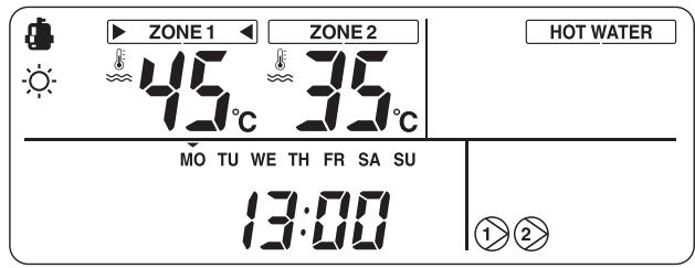
When room temperature control is selected with second remote control, the set temperature will be set room temperature.
Performing Auto mode operation
- The setting temperature can be set automatically according to the outside temperature.
- Press the AUTO TEMP. Ⓐ button.
- The temperature indication changes to “A” and the water temperature is automatically set according to the outside temperature.
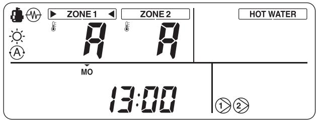
To correct the set value for the Auto mode
- Press the AUTO TEMP. Ⓐ button for 4 seconds or more to enter the auto curve adjusting mode.
- The function code setting screen appears. Press the TIME ▼ ▲ button to display a temperature between -5 to +5°C.
In this case, temperature is displayed as -5, -4, -3, -2, -1, 0, 1, 2, 3, 4, or 5.
Only ZONE1 temperature is displayed.
When the SET ○ button is pressed after the temperature is changed, the set temperature is registered.
- When the TEST ⏻ button is pressed, the registered data is determined. The unit exits the function code setting mode and “A” appears on the display.
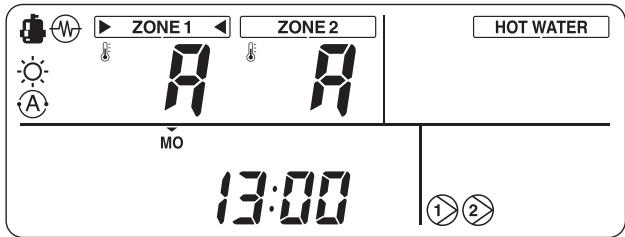
- Each time AUTO TEMP. Ⓐ button is pressed, the mode changes as follows:
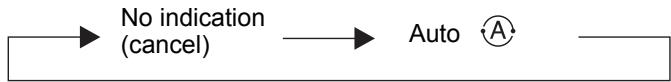
flowchart
graph LR
    A["No indication (cancel)"] --> B["Auto"]
    B --> C[" "]
■ Hot water
Performing hot water supply operation
- Press the HOT WATER ⏻ button to start the hot water supply operation.
- The set temperature appears under HOT WATER on the remote controller, and lights.
- During the heat pump operation or while the internal heater is energized, 📁 or ⏻ is displayed.
Setting temperature
- Press the SELECT ▶ button to move ▶ and select ▶ HOT WATER ◀.
- Change the set temperature with the TEMP. ☑ ▲ button.
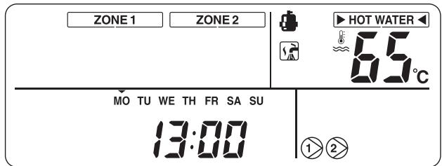
■ Useful functions
Frost protection
This function performs operation with the minimum capacity to prevent pipes from freezing in case the unit is not used for a long period due to absence.
- When the FROST PROTECTION Ⓧ button is pressed during heating (ZONE1 or ZONE2), Ⓧ appears on the remote controller and the temperature indication changes to “F”. The frost protection operation starts with the set minimum capacity (target water temperature: 15°C).
- The frost protection mode can be stopped by either setting the end day and time using function codes or by pressing the FROST PROTECTION Ⓧ button again on the remote controller.
- This function takes precedence over the Night setback quiet operation that are set separately. Ask the installation company for the minimum capacity setting.
- Cancel schedule timer to start frost protection operation. When frost protection is operated with schedule timer on, it may stop during its operation.
Setting the end days and time for the frost protection operation
Press the FROST PROTECTION Ⓧ button for 4 seconds or more while the frost protection operation is enabled (⊗ is displayed on the remote controller), to enter the setting mode.
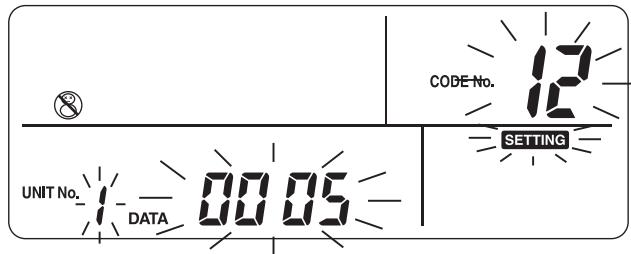
- The setting mode is indicated on the remote controller.
- Select the code number to be set with the TEMP. ☑ ▲ buttons, and set the start time and end time with the TIME ▼ ▲ buttons.
Code No. 12: End days (default 00)
13: End times (default 00)
ex)
Code No. 12: 05
13: 13 = 5 days 13 hours
- Press the SET ○ button to determine the end time and end time.
- Press the TEST ⏻ button to exit the setting mode.
Night setback
This function is used to save heating operation during specified time zone (sleeping hours, etc.) at night.
- When the NIGHT button is pressed during heating (ZONE1 or ZONE2), appears on the remote controller and the night setback operation is reserved. The set temperature is lowered by 5°C between the set start time and end time.
- To stop the night setback operation, press the NIGHT button again to delete the ⚙️ mark on the remote controller.
Setting the start time and end time for the night setback operation
Press the NIGHT button for 4 seconds or more while the night setback operation is enabled (is displayed on the remote controller), to enter the setting mode.
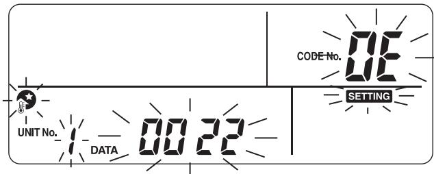
- The setting mode is indicated on the remote controller.
- Select the code number to be set with the TEMP.
▼ ▲ buttons, and set the start time and end time with the TIME ▼ ▲ buttons.
Code No. 0E: Start time (default 22)
OF: End time (default 06) - Press the SET ○ button to determine the start time
and end time. - Press the TEST ⏻ button to exit the setting mode.
Hot water boost
This function is used when temporarily giving priority to the hot water supply operation.
The hot water supply operation is performed in preference to other operations with a target of the preset time (60 minutes) or the preset temperature (75°C). Use this function when hot water is not used for a long time or before using a large amount of hot water.
- When the HOT WATER BOOST button is pressed, the + mark appears on the remote controller and the hot water boost operation starts. When the set time period has passed or the water temperature has reached the set temperature, the hot water boost operation ends automatically.
- The preferential time and temperature settings can be changed to values within a range of 30 to 180 minutes and 40 to 80°C. Ask the installation company for the setting change.
Anti bacteria
This function performs anti-bacteria operation of the hot water tank.
- When the ANTI BACTERIA 📍 button is pressed, the Ⓧ mark appears on the remote controller and the anti-bacteria operation is reserved.
- The anti-bacteria operation is performed to maintain the preset temperature (75°C) for the set time period (30 minutes) when the preset start time (22:00) comes according to the preset interval (7 days).
- The settings of these interval, start time, and temperature maintaining time period can be changed, but ask the installation company for the setting change.
■ Schedule timer
(Disable with second remote control)
Operations can be scheduled in eight STEPs for each day of the week.
(Example)
- Monday
| STEP1 | 04:00 ZONE1 | Heating 45°C, hot water 50°C |
| STEP2 | 07:00 ZONE1 | Heating 50°C, hot water 45°C |
| STEP3 | 10:00 ZONE1 | Heating disabled, hot water 45°C |
| STEP4 | 16:00 ZONE1 | Heating 50°C, hot water 50°C |
| STEP5 | 23:00 ZONE1 | Heating 40°C, hot water 45°C |
• Tuesday to Saturday: Same as Monday
- Sunday
| STEP1 | 04:00 ZONE1 | Heating 45°C, hot water 50°C |
Setting the schedule function
Press the SCHEDULE ⏻ button and press the SET ○ button within five seconds while the ⏻ mark is blinking. The ⏻ mark changes to lighting and the schedule function starts working.
Cancelling the schedule function
Press the SCHEDULE ⏻ button and press the CL ○ button within five seconds while the ⏻ mark is blinking. The ⏻ mark disappears and the schedule function is cancelled.
Setting schedule
Press the SCHEDULE ⏻ button for 4 seconds or more to enter the schedule setting mode.
Perform the following procedure to set the schedule
- First schedule setting
Procedure: 1 2 3 4 5 6
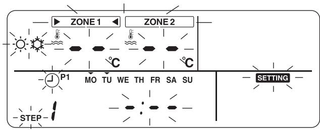
• Existing schedule setting
Procedure: 2 3 4 5 6
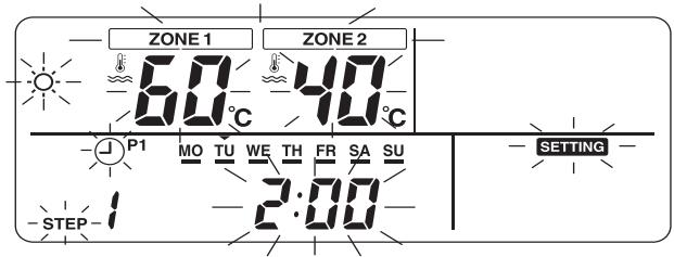
1 Set days of the week.
- Each time the DAY ○ button is pressed, the ▼ mark blinking on the current day of the week at intervals of 1 Hz shifts sequentially.
- When all days are set at a time, all days (MO to SU) blink.
- Press the SET ○ button to determine the set days of the week.
- When the setting is completed, the ▼ mark changes to lighting.
2 Set STEP.
- Select a STEP to be set with the STEP ○ button, and press the SET ○ button to determine the selected STEP.
•1 to 8: Operation program STEP number
•C (Copy): Set s the operation mode for a day (0:00 to 23:59) simultaneously.
•L (Deletion): Deletes all the current program operation settings (for entire week).
$$ \begin{array}{l} 1 \to 2 \to 3 \to 4 \to 5 \to 6 \to 7 \to 8 \to C \to L \to \ 1 \to \dots . \end{array} $$
3 Set the start time.
- Set the start time with the TIME ▼ ▲ buttons.
- When the preset start time is retained, the start time is displayed.
- If no start time is set, “--’-- --” is displayed.
4 Set temperature.
- Set the temperature for ZONE1 or ZONE2 with the SELECT ◀ ▶ button and TEMP. ▼ ▲ buttons.
- Press the SELECT ▶ button so that the ▶ mark lights for the zone to be changed.
- Enter setting temperature with the TEMP. ▼ ▲ buttons.
5 Set operation mode.
- Set the operation mode (heating or cooling) with the OPERATE MODE 📋/💡 button.
6 Determine the settings.
- Press the SET ○ button to determine the settings.
- The “____” mark lights under the set day of the week and the “OK” mark appears on the display for 4 seconds.
- Press the SCHEDULE ⏻ button to end the settings.
Copying data
When “C” is selected during the STEP setting, the setting of the specified day of the week can be copied.
- Press the SET ○ button to determine the copy mode.
- Specify the day of the week of copy destination with the DAY ○ button.
- Each time the DAY ○ button is pressed, the ▼ mark on the specified day of the week blinks sequentially. When all days of the week are blinked, the data can be copied to all days of the week.
- Press the SET ○ button. When the “ok” mark appears on the remote controller for 4 seconds, the setting is completed.
4 USER MAINTENANCE
Periodic maintenance (once a year) is necessary for this product. Consult the installation company.
If a problem occurs, contact the installation company or dealer.
5 AIR TO WATER HEAT PUMP OPERATIONS AND PERFORMANCE
3 minutes protection function
3-minutes protection function prevents the air to water heat pump from starting for initial 3 minutes after the main power switch/circuit breaker is turned on for re-starting the air to water heat pump.
Power failure
Power failure during operation will stop the unit completely.
- To restart the operation, push the ZONE1, 2/HOT WATER button on the remote controller.
Heating characteristics
Defrosting operation
If the outdoor unit is frosted during the heating or hot water supply operation, defrosting starts automatically (for approximately 2 to 10 minutes) to maintain the heating capacity.
- During the defrosting operation, the defrosted water will be drained from the bottom plate of the outdoor unit.
Heating capacity
In the heating operation, the heat is absorbed from the outside and brought into the room. This way of heating is called heat pump system. When the outside temperature is too low, it is recommended to use another heating apparatus in combination with the air to water heat pump.
Attention to snowfall and freeze on the outdoor unit
- In snowy areas, the air inlet and air outlet of the outdoor unit are often covered with snow or frozen up. If snow or freeze on the outdoor unit is left as it is, it may cause machine failure or poor warming.
- In cold areas, pay attention to the drain hose so that it perfectly drains water without water remaining inside for freeze prevention. If water freezes in the drain hose or inside the outdoor unit, it may cause machine failure or poor warming.
Air to water heat pump operating conditions
For proper performance, operate the air to water heat pump under the following temperature conditions:
| Cooling operation | Outdoor temperature : 10°C to 43°C |
| Room temperature : 18°C to 32°C (Dry valve temp.) | |
| Hot water | Outdoor temperature : -20°C to 43°C |
| Room temperature : 5°C to 32°C | |
| Heating operation | Outdoor temperature : -20°C to 25°C |
| Room temperature : 5°C to 32°C |
If air to water heat pump is used outside of the above conditions, safety protection may work.
■ General Specifications
Single Phase model
| Outdoor unit | HWS-803H-E | HWS-1103H-E | HWS-1403H-E | ||
| Power supply | 220-230V ~ 50Hz | ||||
| Type | INVERTER | ||||
| Function | Heating & Cooling | ||||
| Heating | Capacity (kW) | 8.0 | 11.2 | 14.0 | |
| Input (kW) | 1.82 | 2.35 | 3.11 | ||
| COP | 4.40 | 4.77 | 4.50 | ||
| Cooling | Capacity (kW) | 6.0 | 10.0 | 11.0 | |
| Input (kW) | 2.13 | 3.52 | 4.08 | ||
| EER | 2.82 | 2.84 | 2.70 | ||
| Refrigerant | R410A | ||||
| Dimension | HxWxD (mm) | 890x900x320 | 1,340x900x320 | ||
3 Phase model
| Outdoor unit | with bottom plate heater | |||||||
| HWS-1103H8-E | HWS-1403H8-E | HWS-1603H8-E | HWS-1103H8R-E | HWS-1403H8R-E | HWS-1603H8R-E | |||
| Power supply | 380-400V 3N~50Hz | |||||||
| Type | INVERTER | |||||||
| Function | Heating & Cooling | |||||||
| Heating | Capacity (kW) | 11.2 | 14.0 | 16.0 | 11.2 | 14.0 | 16.0 | |
| Input (kW) | 2.39 | 3.21 | 3.72 | 2.39 | 3.21 | 3.72 | ||
| COP | 4.69 | 4.36 | 4.30 | 4.69 | 4.36 | 4.30 | ||
| Cooling | Capacity (kW) | 10.0 | 11.0 | 13.0 | 10.0 | 11.0 | 13.0 | |
| Input (kW) | 3.52 | 4.08 | 4.80 | 3.52 | 4.08 | 4.80 | ||
| EER | 2.84 | 2.70 | 2.71 | 2.84 | 2.70 | 2.71 | ||
| Refrigerant | R410A | |||||||
| Dimension | HxWxD (mm) | 1,340x900x320 | ||||||
| Bottom plate heater (W) | - | 75 | ||||||
80 class
| Hydro Unit | HWS-803XWHM3-E | HWS-803XWHT6-E | HWS-803XWHD6-E | HWS-803XWHT9-E | |
| Back up heater capacity | 3.0 | 6.0 | 9.0 | ||
| Power supply | for back up heater | 220-230V~50Hz | 380-400V 3N~50Hz | 220-230V 3~50Hz | 380-400V 3N~50Hz |
| for hot water cylinder heater (option) | 220-230V~50Hz | ||||
| Leaving water temperature | Heating (°C) | 20-55 | |||
| Cooling (°C) | 10-25 | ||||
112,140,160 class
| Hydro Unit | HWS-1403XWHM3-E | HWS-1403XWHT6-E | HWS-1403XWHD6-E | HWS-1403XWHT9-E | |
| Back up heater capacity | 3.0 | 6.0 | 9.0 | ||
| Power supply | for back up heater | 220-230V~50Hz | 380-400V 3N~50Hz | 220-230V 3~50Hz | 380-400V 3N~50Hz |
| for hot water cylinder heater (option) | 220-230V~50Hz | ||||
| Leaving water temperature | Heating (°C) | 20-55 | |||
| Cooling (°C) | 10-25 | ||||
| Hot water cylinder (option) | HWS-1501CSHM3-EHWS-1501CSHM3-UK | HWS-2101CSHM3-EHWS-2101CSHM3-UK | HWS-3001CSHM3-EHWS-3001CSHM3-UK | ||
| Power supply | 220-230V~ 50Hz | ||||
| Water volume | (liter) | 150 | 210 | 300 | |
| Max water temperature | (°C) | 75 | |||
| Electric heater | (kW) | 2.75 | |||
| Height | (mm) | 1,090 | 1,474 | 2,040 | |
| Diameter | (mm) | 550 | |||
| Material | Stainless steel | ||||
6 TROUBLESHOOTING
If a problem occurs, contact the installation company or dealer.
| Problem Check | Action |
| Nothing is displayed on the remote controller. | Check whether power is supplied.Is the circuit breaker switch turned on? |
| Time indication is blinking. | Date/time setting is not made.Set date and time. |
| An error code is displayed on the remote controller. | Contact the installation company. |
| Room is not cooled or heated. | Is scheduled operation set?Check whether scheduled operation is set. |
| Is night setback operation set?Check the setting on the remote controller. | |
| Is the air to water heat pump operating in Auto mode?In Auto mode, the target value is set automatically according to the outdoor unit temperature.The Auto mode can be adjusted. Contact the installation company. | |
| Hot water is not supplied. | Is the main water supply cock closed?Check valves. |
| Are you using too much hot water?If hot water exceeding the storage capacity is used, water at a temperature lower than the set hot water temperature is supplied. |
If you have any questions, contact the installation company.
Air to Water Heat Pump Engineering Data Book
- Engineering Data Book
- Air to Water Heat Pump
- Hydro Unit
- Outdoor Unit
- Hot Water Cylinder
- Contents
- INTRODUCTION
- Air to water
- Heat Pump System
- Advantages
- World-leading energy efficiency - COP of 4.77\*
- Easy to install
- Environment conscious
- One system, multiple solutions
- The right temperature at the right time
- One system, full combination flexibility
- SYSTEM OVERVIEW
- 2-1. System Combination
- 2-2. Hydro Unit
- 2-3. Outdoor Unit
- 2-4. Hot Water Cylinder
- SYSTEM SPECIFICATION
- HYDRO UNIT
- 4-1. Specification
- 4-1-1. Hydro unit specifications
- 4-2. Dimension
- ▼External output board (TCB-PCIN3E)
- ▼External input board (TCB-PCMO3E)
- 4-3. Piping Diagram
- Water system diagram
- Refrigeration cycle system diagram
- 4-4. Wiring Diagram
- 4-4-1. Hydro unit
- 4-4-2. Power line
- Electrical connection to hydro unit
- 4-4-4. External Device
- 3-way valve (diverter) connection
- Required Valve Specification:
- 3-way mixing valve connection
- Required Actuator Specification
- 4-5. Capacity Tables
- ▼Outdoor unit HWS-803H-E Hydro unit HWS-803XWH\*\*-E
- Heating capacity and input specifications
- ▼Outdoor unit HWS-1103H-E Hydro unit HWS-1403XWH\*\*-E
- Cooling capacity and input specifications
- ▼Outdoor unit HWS-1403H-E Hydro unit HWS-1403XWH\*\*-E
- ▼Outdoor unit HWS-1103H8-E, HWS-1103H8R-E Hydro unit HWS-1403XWH\*\*-E
- ▼Outdoor unit HWS-1403H8-E, HWS-1403H8R-E Hydro unit HWS-1403XWH\*\*-E
- ▼Outdoor unit HWS-1603H8-E, HWS-1603H8R-E Hydro unit HWS-1403XWH\*\*-E
- 4-6. Q-H characteristics of hydro unit 4-6-1. HWS-803XWHM3-E, T6-E, D6-E, T9-E
- 4-6-2. HWS-1403XWHM3-E, T6-E, D6-E, T9-E
- 4-7. Options
- Optional parts
- ▼External output board
- Feature
- Function / Electric wiring diagram
- CAUTION
- ▼External input board
- Room thermostat input
- Emergency shutdown input
- OUTDOOR UNIT
- 5-1. Specification
- 5-2. Dimension 5-2-1. HWS-803H-E
- 5-2-2. HWS-1103H-E, HWS-1403H-E, HWS-1603H-E HWS-1103H(R)-E, HWS-1403H(R)-E, HWS-1603H(R)-E
- 5-3. Piping Diagram
- 5-4. Wiring Diagram
- 5-4-1. Outdoor Unit (Single phase type)
- 5-4-2. Outdoor unit (3 phase type)
- 5-4-3. Power line
- 5-4-4. Wiring between Hydro Unit and Outdoor Unit
- 5-5. Sound Data
- 5-5-1. Sound pressure level measurement
- 5-5-2. Sound Characteristics (NC Curve)
- ▼HWS-803H-E
- ▼HWS-1103H-E, 1103H8(R)-E
- ▼HWS-1403H-E, 1403H8(R)-E
- ▼HWS-1603H8(R)-E
- 5-6. Operation Range
- kW class
- Cooling operation
- NOTE
- HOT WATER CYLINDER
- 6-2. Dimension
- General dimensions and performance
- 6-3. Piping Diagram
- Typical discharge pipe arrangement (extract from Building Regulation G3 Guidance section 3.9)
- 6-4. Wiring Diagram
- Thermal cut-out
- NOTE:
- HYDRO UNIT INSTALLATION MANUAL
- ADOPTION OF NEW REFRIGERANT
- GENERAL INFORMATION
- ■ General Specifications
- ACCESSORY PARTS
- PREPARATIONS FOR INSTALLATION
- PRECAUTIONS FOR SAFETY
- ■ General Safety Precautions
- ■ Refrigerant Precautions
- WARNING
- Installation Precautions
- ■ Notes on System Design
- EXAMPLE OF HYDRO UNIT INSTALLATION
- ■ Example of Installation for Cooling and Heating
- ■ Example of 2-Zone Temperature Control and Hot Water Supply System
- MAIN COMPONENTS OF HYDRO UNIT
- ■ Exploded view and description for Hydro Unit
- ■ E-Box layout
- ■ Handling, Unpacking, and Checking the Hydro Unit
- ■ Positioning
- Service space
- Mounting
- ■ Refrigerant Piping
- Refrigeration pipe
- Flaring
- Tightening
- ■ Water Pipe
- Water pipe
- Water circuit
- Piping to hot water cylinder (option)
- Piping to 2-zone operation
- Checking water volume and initial pressure of expansion vessel
- Expression for expansion vessel selection
- Pump operation/configuration
- Water charging
- Water quality
- Piping insulation
- ■ Electrical Installation
- Control line
- Electrical supply/cable specifications
- Earthing arrangements
- Outdoor unit to hydro unit electrical connection
- Electrical connection for external booster heater
- Electrical connection for external additional pumps
- Hot water cylinder connection (optional)
- Electrical Connection (Hot Water Cylinder Electric Heater)
- Electrical Connection (Hot Water Cylinder temperature Sensor)
- Additional hydro unit outputs
- Alarm and Boiler Outputs
- Alarm Output: L1: Alarm output
- Boiler Control Output: L2: Boiler drive permission output
- Defrost and Compressor operation Outputs Defrost output
- Compressor operation output
- Optional inputs to hydro unit
- Room Thermostat Input:
- Electrical safety checks
- Earth continuity test
- Insulation resistance test
- ■ Second remote controller
- Installation place
- Remote controller installation dimension
- Remote controller installation
- Remote controller wiring
- Connection diagram
- Second remote controller installation requirements
- Installation
- START UP AND CONFIGURATION
- ■ Setting DIP Switches on the Board in the Hydro Unit
- ■ Setting DIP Switches on the Board in Second Remote controller (option)
- ■ Setting Function Codes for Hydro Unit and Remote Controller
- Setting remote controller mode
- Main setting items
- (14)Mixing valve operation setting
- (15)Setting Heating/Hot Water Switching when Boiler Is Used (function code 3E)
- (16)Setting Heat Pump Operating Time for Hot Water Supply Operation
- (17)Setting Cooling ON/OFF
- (18)Remote controller time indication
- (19)Setting Nighttime Quiet Operation
- (20)Setting Alarm Tone
- (21)Selection of mode of operation by external input.
- ■ Settings by Purpose
- Settings when hot water supply function is not used
- Setting for cooling
- Settings for hot water supply
- Settings for 2-zone temperature control
- Setting for second remote controller
- TEST RUN
- MAINTENANCE
- Check points
- SENSOR TEMPERATURE MONITORING FUNCTION
- TROUBLESHOOTING
- MEMO
- OUTDOOR UNIT INSTALLATION MANUAL
- TOSHIBA
- Original instruction
- ▼ HWS-803H-E, HWS-1103H-E, HWS-1403H-E
- ▼ HWS-1103H8-E, HWS-1103H8R-E HWS-1403H8-E, HWS-1403H8R-E HWS-1603H8-E, HWS-1603H8R-E
- ■ Generic Denomination: Air to water heat pump
- ■ Definition of Qualified Installer or Qualified Service Person
- ■ Definition of Protective Gear
- Warning Indications on the Air to water heat pump Unit
- PRECAUTIONS FOR SAFETY
- New Refrigerant Air to Water Heat Pump Installation
- To Disconnect the Appliance from Main Power Supply
- ACCESSORY PARTS AND REFRIGERANT
- INSTALLATION OF NEW REFRIGERANT AIR TO WATER HEAT PUMP
- ■ Required Tools/Equipment and Precautions for Use
- Legend
- New refrigerant (R410A)
- When using the conventional piping kit
- When using general copper pipes
- Flare nuts and flare machining
- INSTALLATION CONDITIONS
- ■ Before installation
- ■ Airtight test
- Air purge
- Electrical wiring
- Earthing
- Test Run
- ■ Installation Location
- Install the outdoor unit in a location that meets the following conditions after the customer's consent is obtained.
- Do not install the outdoor unit in the following locations.
- ■ Necessary Space for Installation
- Obstacle at rear side
- Upper side is free
- Obstacle also above unit
- Obstacle in front
- Above unit is free
- Obstacle also at the above unit
- Obstacles in both front and rear of unit
- Standard installation
- Serial installation of two or more units
- Serial installation in front and rear
- ■ Installation of Outdoor Unit
- ■ For Reference
- REFRIGERANT PIPING
- ■ Knockout of Pipe Cover
- ■ Optional Installation Parts (Locally procured)
- ■ Refrigerant Piping Connection
- TAKE NOTE OF THESE 4 IMPORTANT POINTS BELOW FOR PIPING WORK
- Projection margin in flaring: B (Unit: mm)
- Flaring diameter size: A (Unit: mm)
- Piping necessary to change the flare nut/machining size due to pipe compression
- ▼ Flare nut width: H and flare matching size: A.
- ■ Tightening of Connecting Part
- ■ Refrigerant Pipe Length
- AIR PURGING
- Vacuum pump
- Tighten the valve and caps of the charge port securely.
- ■ How to open the valve
- Liquid side
- Valve handling precautions
- ■ Replenishing refrigerant
- Refrigerant replenishing procedure
- Requirement for replenishing refrigerant
- Adding additional refrigerant
- ELECTRICAL WORK
- ■ Wiring between Hydro Unit and Outdoor Unit
- How to wire
- EARTHING
- FINISHING
- 10TEST RUN
- AIR TO WATER HEAT PUMP OPERATING CONDITIONS
- FUNCTIONS TO BE IMPLEMENTED LOCALLY
- ■ Handling Existing Pipe
- Cautions for using existing pipe
- ■ Recovering Refrigerant
- Procedure
- DANGER
- TROUBLESHOOTING
- Verifying current abnormal status
- Verifying an abnormal state in the past although the abnormal state no longer occurs
- ▼ HWS-1103H8-E, H8R-E
- 15APPENDIX
- ■ Work instructions
- Basic conditions needed to reuse existing pipes
- Restrictions for use of existing pipes
- Curing of pipes
- CE
- IMPORTANT INFORMATION AND WARNING:
- OWNER'S MANUAL
- SAFETY PRECAUTIONS
- INSTALLATION WARNINGS
- OPERATION WARNINGS
- WARNINGS AT MOVEMENT AND REPAIR
- TO DISCONNECT THE APPLIANCE FROM THE MAIN POWER SUPPLY
- INSTALLATION CAUTIONS
- OPERATION CAUTIONS
- NAMES AND FUNCTIONS OF PARTS
- ■ Buttons
- ■ Meaning of Indication
- HOW TO USE FUNCTIONS
- ■ Timer setting
- First, set the current time on the remote controller.
- ■ Heating or cooling operation
- Performing heating or cooling operation
- Setting temperature
- Performing Auto mode operation
- To correct the set value for the Auto mode
- ■ Hot water
- Performing hot water supply operation
- ■ Useful functions
- Frost protection
- Setting the end days and time for the frost protection operation
- Night setback
- Setting the start time and end time for the night setback operation
- Hot water boost
- Anti bacteria
- ■ Schedule timer
- (Example)
- Setting the schedule function
- Cancelling the schedule function
- Setting schedule
- Perform the following procedure to set the schedule
- Set days of the week.
- Set STEP.
- Set the start time.
- Set temperature.
- Set operation mode.
- Determine the settings.
- Copying data
- USER MAINTENANCE
- AIR TO WATER HEAT PUMP OPERATIONS AND PERFORMANCE
- minutes protection function
- Power failure
- Heating characteristics
- Defrosting operation
- Heating capacity
- Attention to snowfall and freeze on the outdoor unit
- Air to water heat pump operating conditions
- TROUBLESHOOTING
- Air to Water Heat Pump Engineering Data Book
Brand : TOSHIBA
Model : HWS-1403H-E
Category : Heat pump