
A-10-K - Audio Amplifier PIONEER - Free user manual and instructions
Find the device manual for free A-10-K PIONEER in PDF.
| Product type | Integrated stereo audio amplifier |
| Brand | Pioneer |
| Model | A-10-K |
| Output power | 50 W + 50 W (4 Ω, 0.1% THD); 30 W + 30 W (8 Ω, 0.05% THD) |
| Dimensions (W x H x D) | 435 mm x 128 mm x 360 mm |
| Weight (net) | 6.7 kg |
| Power supply | 220–230 V AC, 50 Hz |
| Power consumption | 135 W (in operation); 0.3 W (standby) |
| Speaker impedance | 4 Ω to 16 Ω (A or B alone); 8 Ω to 32 Ω (A+B); 4 Ω to 16 Ω (bi-wiring) |
| Audio inputs | Phono (MM), Tuner, SACD/CD, AUX, Network, Recorder IN |
| Audio outputs | Speakers A and B, headphones (PHONES), Recorder OUT |
| Main functions | Direct, Loudness, tone control (Bass, Treble, Balance), auto power down (APD) |
| Supplied accessories | Power cord, warranty card, user manual |
| Remote control | Not supplied (A-10 model without remote control) |
| Operating temperature | +5 °C to +35 °C |
| Operating humidity | Less than 85% RH (no condensation) |
| Ventilation | Clearance: 30 cm above, 10 cm at rear and sides |
| Maintenance and cleaning | Dry cloth; do not use solvents or chemicals |
| Safety | Disconnect before any connection; do not expose to water; do not obstruct ventilation slots |
| Warranty | Refer to supplied warranty card |
Frequently Asked Questions - A-10-K PIONEER
User questions about A-10-K PIONEER
0 question about this device. Answer the ones you know or ask your own.
Ask a new question about this device
Download the instructions for your Audio Amplifier in PDF format for free! Find your manual A-10-K - PIONEER and take your electronic device back in hand. On this page are published all the documents necessary for the use of your device. A-10-K by PIONEER.
USER MANUAL A-10-K PIONEER
The lightning flash with arrowhead symbol, within an equilateral triangle, is intended to alert the user to the presence of uninsulated "dangerous voltage" within the product's enclosure that may be of sufficient magnitude to constitute a risk of electric shock to persons.
CAUTION
RISK OF ELECTRIC SHOCK DO NOT OPEN
CAUTION:
TO PREVENT THE RISK OF ELECTRIC SHOCK,DO NOT REMOVE COVER (OR BACK).NO USER-SERVICEABLE PARTS INSIDE.REFER SERVICING TO QUALIFIED SERVICE PERSONNEL.

The exclamation point within an equilateral triangle is intended to alert the user to the presence of important operating and maintenance (servicing) instructions in the literature accompanying the appliance.
D3-4-2-1-1_A1_En
European model only
Information for users on collection and disposal of old equipment and used batteries
Symbol for equipment

(Symbol examples) for batteries


These symbols on the products, packaging, and/or accompanying documents mean that used electrical and electronic products and batteries should not be mixed with general household waste.
For proper treatment, recovery and recycling of old products and used batteries, please take them to applicable collection points in accordance with your national legislation.
By disposing of these products and batteries correctly, you will help to save valuable resources and prevent any potential negative effects on human health and the environment which could otherwise arise from inappropriate waste handling.
For more information about collection and recycling of old products and batteries, please contact your local municipality, your waste disposal service or the point of sale where you purchased the items.
These symbols are only valid in the European Union.
For countries outside the European Union:
If you wish to discard these items, please contact your local authorities or dealer and ask for the correct method of disposal.
K058a_A1_En
WARNING
This equipment is not waterproof. To prevent a fire or shock hazard, do not place any container filled with liquid near this equipment (such as a vase or flower pot) or expose it to dripping, splashing, rain or moisture.
D3-4-2-1-3_A1_En
WARNING
Before plugging in for the first time, read the following section carefully.
The voltage of the available power supply differs according to country or region. Be sure that the power supply voltage of the area where this unit will be used meets the required voltage (e.g., 230 V or 120 V) written on the rear panel.
D3-4-2-1-4*A1En
WARNING
To prevent a fire hazard, do not place any naked flame sources (such as a lighted candle) on the equipment.
D3-4-2-1-7a_A1_En
VENTILATION CAUTION
When installing this unit, make sure to leave space around the unit for ventilation to improve heat radiation (at least 30~cm at top, 10~cm at rear, and 10~cm at each side).
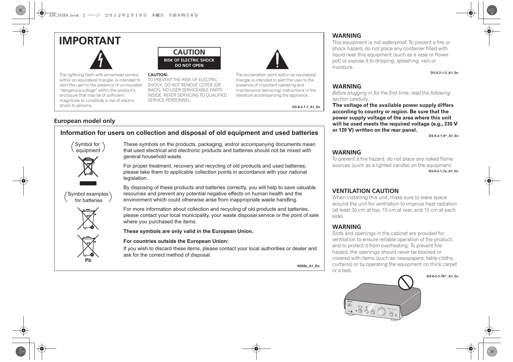
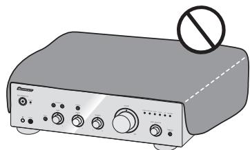
WARNING
Slots and openings in the cabinet are provided for ventilation to ensure reliable operation of the product, and to protect it from overheating. To prevent fire hazard, the openings should never be blocked or covered with items (such as newspapers, table-cloths, curtains) or by operating the equipment on thick carpet or a bed.
D3-4-2-1-7b*A1En
Operating Environment
Operating environment temperature and humidity: +5 C to +35 C ( +41 ~F to +95 ~F ); less than 85 % RH (cooling vents not blocked)
Do not install this unit in a poorly ventilated area, or in locations exposed to high humidity or direct sunlight (or strong artificial light)
D3-4-2-1-7c*A1_EN
If the AC plug of this unit does not match the AC outlet you want to use, the plug must be removed and appropriate one fitted. Replacement and mounting of an AC plug on the power supply cord of this unit should be performed only by qualified service personnel. If connected to an AC outlet, the cut-off plug can cause severe electrical shock. Make sure it is properly disposed of after removal. The equipment should be disconnected by removing the mains plug from the wall socket when left unused for a long period of time (for example, when on vacation).
D3-4-2-2-1a_A1_En
CAUTION
The / STANDBY/ON switch on this unit will not completely shut off all power from the AC outlet. Since the power cord serves as the main disconnect device for the unit, you will need to unplug it from the AC outlet to shut down all power. Therefore, make sure the unit has been installed so that the power cord can be easily unplugged from the AC outlet in case of an accident. To avoid fire hazard, the power cord should also be unplugged from the AC outlet when left unused for a long period of time (for example, when on vacation).
D3-4-2-2-2a*A1En
This product is for general household purposes. Any failure due to use for other than household purposes (such as long-term use for business purposes in a restaurant or use in a car or ship) and which requires repair will be charged for even during the warranty period.
K041_A1_En
POWER-CORD CAUTION
Handle the power cord by the plug. Do not pull out the plug by tugging the cord and never touch the power cord when your hands are wet as this could cause a short circuit or electric shock. Do not place the unit, a piece of furniture, etc., on the power cord, or pinch the cord. Never make a knot in the cord or tie it with other cords. The power cords should be routed such that they are not likely to be stepped on. A damaged power cord can cause a fire or give you an electrical shock. Check the power cord once in a while. When you find it damaged, ask your nearest PIONEER authorized service center or your dealer for a replacement.
S002*A1_EN
(A-30 only)

CAUTION: HOT SURFACE. DO NOT TOUCH.
The top surface over the internal heatsink may become hot when operating this product continuously.
Thank you for buying this Pioneer product.
Please read through these operating instructions so that you will know how to operate your model properly. After you have finished reading the instructions, put them in a safe place for future reference.
Contents
01 Before you start
What's in the box. 4
Loading the batteries in the remote control (Except A-10). 4 Using the remote control. 4
Installing the amplifier. 4
02 Connecting up
Making cable connections. 5
About "Bi-wiring" 5
Connecting speaker cables 6
Connecting audio cables.. 6
Using centralized control with other Pioneer components (Except A-10). 6
Plugging in 6
03 Controls and displays
Front panel 7
Rear panel. 8
Remote control (Except A-10) 9
04 Operation
Playback 10
Set the power to Standby. 10
When using the unit as a power amplifier (A-30 only). 10
Making an audio recording 11
To set for automatic standby status (Auto Power Down) 11
Restoring all the settings to the factory default settings 11
05 Additional information
Troubleshooting. 12
Cleaning the unit. 12
Specifications 13
Chapter 1:
Before you start
What's in the box
Please confirm that the following accessories are in the box when you open it.
Remote control (Except A-10)
- AAA/IEC R03 dry cell batteries x2 (Except A-10)
Power cord
Warranty card
- Operating instructions (This document)

Note
- Illustrations featured in the Operating Instructions may have been modified or simplified for ease of explanation, and may therefore differ from the actual product appearance.
The illustrations used here are mainly of the A-30.
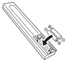
Loading the batteries in the remote control (Except A-10)
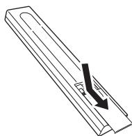
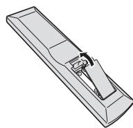
1 Open the rear lid.
A-30
A-20
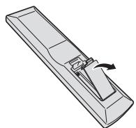
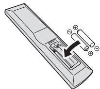
2 Insert the new batteries, matching the polarities as indicated inside the case.
A-30
A-20
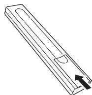
3 Close the rear lid.
A-30
A-20
The batteries included with the unit have been provided to allow you check product operation and may not last long. We recommend using alkaline batteries that have a longer life.

WARNING
- Do not use or store batteries in direct sunlight or other excessively hot place, such as inside a car or near a heater. This can cause batteries to leak, overheat, explode or catch fire. It can also reduce the life or performance of batteries.

Caution
Incorrect use of batteries may result in such hazards as leakage and bursting. Observe the following precautions:
-
When inserting the batteries, make sure not to damage the springs on the battery's terminals.
-
Do not use any batteries other than the ones specified. Also, do not use a new battery together with an old one.
- When loading the batteries into the remote control, set them in the proper direction, as indicated by the polarity marks (⊕ and ⊙).
- Do not heat batteries, disassemble them, or throw them into flames or water.
- Batteries may have different voltages, even if they are the same size and shape. Do not use different types of batteries together.
- To prevent leakage of battery fluid, remove the batteries if you do not plan to use the remote control for a long period of time (1 month or more). If the fluid should leak, wipe it carefully off the inside of the case, then insert new batteries. If a battery should leak and the fluid should get on your skin, flush it off with large quantities of water.
- When disposing of used batteries, please comply with governmental regulations or environmental public institution's rules that apply in your country/area.
Using the remote control
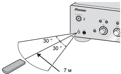
The remote has a range of about 7 m at an angle of about 30^ from the remote sensor.
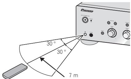
Keep in mind the following when using the remote control:
- Make sure that there are no obstacles between the remote and the remote sensor on the unit.
- Remote operation may become unreliable if strong sunlight or fluorescent light is shining on the unit's remote sensor.
- Remote controllers for different devices can interfere with each other. Avoid using remotes for other equipment located close to this unit.
- Replace the batteries when you notice a fall off in the operating range of the remote.
Installing the amplifier
When installing this unit, make sure to put it on a level and stable surface.
-on a color TV (the screen may distort)
- near a cassette deck (or close to a device that gives off a magnetic field). This may interfere with the sound.
- Don't install it on the following places:
-in direct sunlight
-in damp or wet areas - in extremely hot or cold areas
- in places where there is vibration or other movement
- in places that are very dusty
- in places that have hot fumes or oils (such as a kitchen)
- Do not mount the unit on a sofa or other object or material with absorbent qualities, since sound quality may be adversely affected.
Chapter 2:
Connecting up
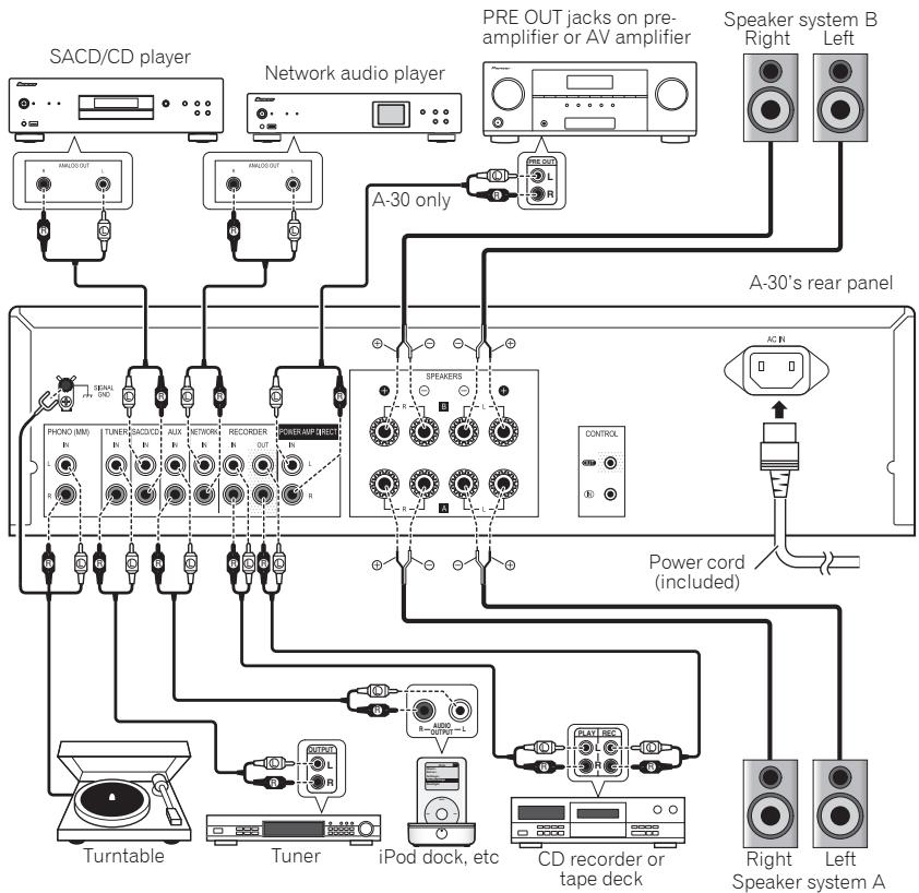
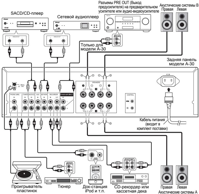
Making cable connections

Caution
Before making or changing the connections, switch off the power and disconnect the power cord from the AC outlet.
- Connect the power cord after all the connections between devices have been completed.

Caution
- The SIGNAL GND terminal is provided to reduce noise when connecting the unit to components such as an analog turntable.
- Do not connect the PHONO (MM) terminals to any component other than a turntable; also, do not connect to a turntable equipped with built-in equalizer. An excessively high sound output may be produced, resulting in damage to your speakers or other devices.
- The unit's PHONO (MM) terminals are designed to be used with turntables equipped with MM (moving-magnet) type cartridges. Turntables equipped with MC (moving-coil) cartridges cannot be used.
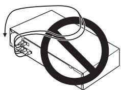
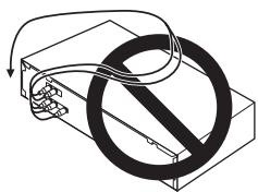
- Make sure not to bend the cables over the top of this unit (as shown in the illustration). If this happens, the magnetic field produced by the transformers in this unit may cause a humming noise from the speakers.
- The unit's POWER AMP DIRECT terminals should never be connected to any other component's connectors except PRE-AMP OUT.
- If your turntable has a grounding wire, secure it to the ground terminal on this amplifier.

Note
- When connecting a tape cassette deck, playback noise may be heard, depending on the installation location. This noise is caused by leakage flux from the amplifier's transformer. In this event, change the installation location, or move the deck farther from the amplifier.
- iPod is a trademark of Apple Inc., registered in the U.S. and other countries.
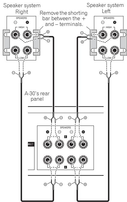
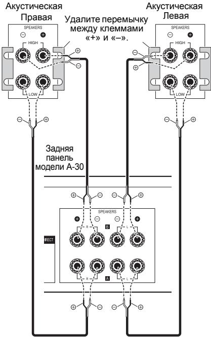
About "Bi-wiring"
This unit can be used with speakers that support biwiring. Be sure to connect the high-frequency and low-frequency connections correctly.
- During playback, be sure that both the SPEAKERS A button and SPEAKERS B button are set to ON (page 7).

Caution
- When using bi-wiring to connect speakers, avoid adverse affects on the amplifier by being sure to remove the HIGH and LOW short bars provided with the speakers. For detailed information, consult the instructions provided with the speakers.
- When using speakers with removable network circuits, note that if the network is removed, no effect will be produced and damage may be caused to the speaker.
- Another method of connection is to connect the SPEAKERS A terminals to HIGH and the SPEAKERS B terminals to LOW (reverse that shown in the illustration).
Connecting speaker cables
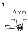
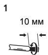
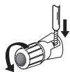
1 Twist the cable cores.
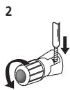
2 Loosen the nut on the SPEAKERS terminal, and insert the speaker cable into the exposed hole in the terminal shaft.
3 Retighten the terminal nut.

Caution
- When using only one set of speaker terminals (SPEAKERS A or SPEAKERS B), or when utilizing bi-wiring connections, the speaker used should have a nominal impedance between 4 Ω and 16 Ω. When using both sets of terminals, the connected speakers should have nominal impedance between 8 Ω and 32 Ω. Consult the instructions accompanying your speakers for details regarding the impedance value.
- Make sure the positive and negative (+/-) terminals on the amplifier match those on the speakers.
- These speaker terminals carry HAZARDOUS live voltage. To prevent the risk of electric shock when connecting or disconnecting the speaker cables, disconnect the power cord before touching any uninsulated parts.
- Make sure that all the bare speaker wire is twisted together and inserted fully into the speaker terminal. If any of the bare speaker wire touches the back panel it may cause the power to cut off as a safety measure.
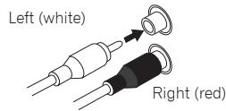
Connecting audio cables
Connect the white plug to the left (L) jack, and the red plug to the right (R) jack. Be sure to insert the plugs fully into the jacks.
Using centralized control with other Pioneer components (Except A-10)
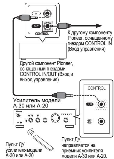
Multiple Pioneer components equipped with CONTROL IN/OUT jacks can be connected to the A-30/A-20 unit, allowing centralized control of the components via the remote sensor on the A-30/A-20. This also allows remote control of components not equipped with a remote sensor, or installed in places where the component's remote sensor cannot be accessed.
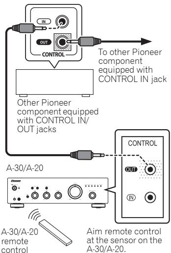

Note
For connections use a commercially available monaural miniplug cord (without resistor).
- When connecting the CONTROL IN/OUT jacks, commercially available audio cords must also be used to make analog connections. Merely connecting the CONTROL IN/OUT jacks alone will not allow proper system control.
- When a control cord is connected to the A-30/A-20's CONTROL IN jack, the unit cannot be controlled by pointing the remote control at the A-30/A-20 (the remote sensor is automatically disabled).
Plugging in

Important
- When going on a trip or otherwise not using the unit for an extended period, always disconnect the power cord from its outlet. Note that various internal settings will not be lost even if the power cord is disconnected from its outlet for an extended time.
- If it is necessary to detach the power cord, first be sure to press the O/I STANDBY/ON button on the front panel of the unit so the A-30/A-20 is turned OFF or the A-10 is in standby mode before detaching the cord.

Caution
- The use of a power cord other than the one provided will invalidate the warranty, since Pioneer will not be responsible for any damage incurred. (The power cord provided with the model A-30 has a rated current capacity of 10 A, while the cord provided with the A-20/A-10 has a rated current capacity of 2.5 A.)
- Do not use any power cord other than the one supplied with this unit.
- Do not use the supplied power cord for any purpose other than that described below.
After you've finished making all connections, plug the unit into an AC outlet.
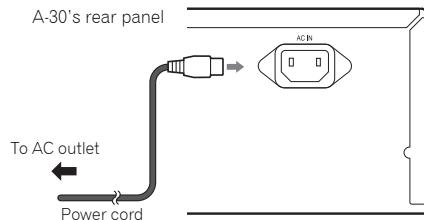
1 Plug the supplied power cord into the AC IN socket on the rear panel of the unit.
2 Plug the other end into an AC outlet.
Chapter 3:
Controls and displays
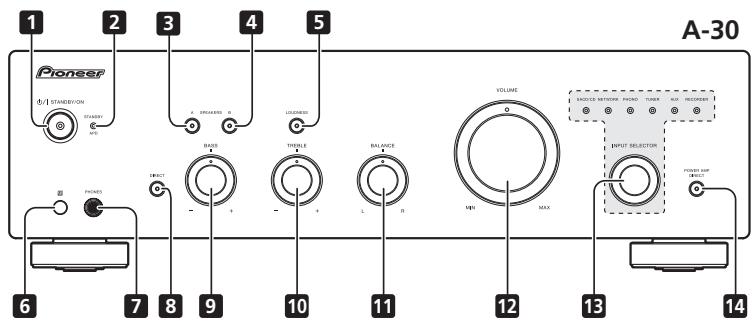
Front panel
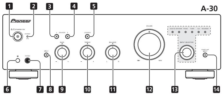
1 /STANDBY/ON
Switches the amplifier between off and on. When power is turned on, the power indicator center of the button will light.
- On the A-10 model, this switches the amplifier between standby and on.
2 STANDBY/APD indicator
When power is set to standby, the indicator lights red. When the Auto Power Down (APD) function is on, the indicator lights green (page 11).
3 SPEAKERS A button/indicator
Use this button to listen to the speaker system connected to SPEAKERS A terminals.
On : The indicator lights. Sound is heard from the speaker system. (Sound will also be produced from the PHONES jack.)
Off : The indicator goes off. No sound is heard from the speaker system. Set to this position when listening with headphones.
4 SPEAKERS B button/indicator
Use this button to listen to the speaker system connected to SPEAKERS B terminals.
On : The indicator lights. Sound is heard from the speaker system. (Sound will also be produced from the PHONES jack.)
Off: The indicator goes off. No sound is heard from the speaker system. Set to this position when listening with headphones.
5 LOUDNESS button/indicator
Use when listening at low volume levels.
On: The indicator lights: Boosts low and high frequencies to give added punch to playback even at a low volume level.
Off: The indicator goes off: Should normally be left in this position.
- This button does not operate when the DIRECT button is in the on position.
- When sound volume is raised, the amount of change produced by the LOUDNESS circuit is reduced.
6 Remote sensor (Except A-10)
Receives the signals from the remote control (page 4).
7 PHONES jack
Use to connect headphones. No sound is produced when the POWER AMP DIRECT button is ON.
8 DIRECT button/indicator
On: The indicator lights: When this button is set to ON, sound signals are output directly, without being passed through the various adjustment circuits (BASS, TREBLE, BALANCE, LOUDNESS). This allows reproduction of the signals with greater fidelity, but it disables any settings made with the BASS, TREBLE, BALANCE or LOUDNESS controls.
Off: The indicator goes off: The signal passes through the various frequency adjusting circuits. When the indicator is OFF, adjustments can be made with the BASS, TREBLE, BALANCE, and LOUDNESS controls.
9 BASS tone control
Use to adjust the low-frequency tone. The center position is the flat (normal) position. When turned to the right, low-frequency tones are emphasized; when turned to the left, low-frequency tones are de-emphasized.
- This button does not operate when the DIRECT button is in the on position.
10 TREBLE tone control
Use to adjust the high-frequency tone. The center position is the flat (normal) position. When turned to the right, high-frequency tones are emphasized; when turned to the left, high-frequency tones are de-emphasized.
- This button does not operate when the DIRECT button is in the on position.
11 BALANCE control
Should normally be left in the center position. Adjust balance if the sound is louder from one of the speakers. If the right side is louder, turn toward the L (left) position and if the left side is louder, turn toward the R (right) position.
- This button does not operate when the DIRECT button is in the on position.
12 VOLUME control
Use to adjust the volume level. (Also allows adjustment of the headphone sound volume.)
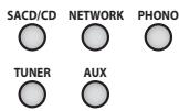
13 INPUT SELECTOR knob/indicators
Turn the knob clockwise or counterclockwise so that the indicator lights for your desired input source. Turning the knob clockwise causes the lit indicator to right. Turning counterclockwise causes it to left. When the remote control's MUTE button is pressed to mute the sound, the indicator for the input source selected with the INPUT SELECTOR knob flashes.
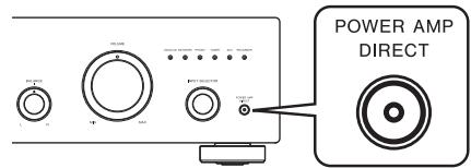
14 POWER AMP DIRECT button/indicator (A-30 only)
Press this button when the A-30 is to be used as a power amplifier (page 10).
Rear panel
See pages 5-6 for details regarding connections.
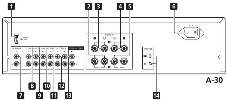
1 GND (Turntable ground) terminal
This ground terminal is designed to help reduce noise when a turntable is connected. It is not a safety ground.
2 SPEAKERS A terminals (Right channel)
3 SPEAKERS B terminals (Right channel)
4 SPEAKERS B terminals (Left channel)
5 SPEAKERS A terminals (Left channel)
6 AC IN jack
Connect power cord to here and an AC wall socket.
7 PHONO (MM) IN terminals
8 TUNER IN terminals
9 SACD/CD IN terminals
10 AUX IN terminals
11 NETWORK IN terminals
12 REORDER IN/OUT terminals
13 POWER AMP DIRECT IN terminals (A-30 only)
When using the A-30 as a power amplifier, connect the pre-amplifier here (page 10).
14 CONTROL IN/OUT jack (Except A-10)
Remote control (Except A-10)
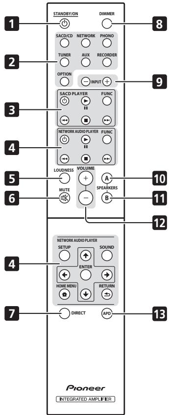
A-30
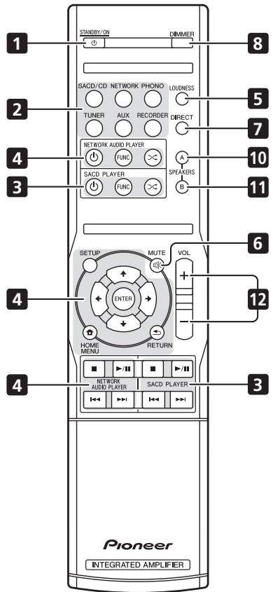
A-20
1 STANDBY/ON
Switches the amplifier between standby and on.
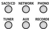
2 Input selector buttons
Press to select an input source. These select the component connected to the corresponding input on the rear panel.
- When the A-30 is connected, the OPTION button is disabled.
3 SACD PLAYER control buttons
Use to control Pioneer SACD player.
(Cannot be used to perform playback/pause on the PD-D6/PD-D6MK2/PD-D9/PD-D9MK2 models.)
4 NETWORK AUDIO PLAYER control buttons
Use to control Pioneer network audio player.
5 LOUDNESS
Use to set the loudness circuit ON/OFF (page 7).
6 MUTE
Mutes/unmates the sound.
7 DIRECT
Press to access Direct listening (page 7).
8 DIMMER
This button allows the illumination of the unit's front panel indicators to be set in three levels (does not affect the STANDBY indicator).
9 INPUT + / -
Use to change the input source. The source changes as below.
SACD/CD NETWORK PHONO TUNER
AUX RECORDER Return to the beginning.
10 SPEAKERS A button/indicator
Use this button to listen to the speaker system connected to SPEAKERS A terminals.
11 SPEAKERS B button/indicator
Use this button to listen to the speaker system connected to SPEAKERS B terminals.
12 VOLUME + / -
Use to set the listening volume.
13 APD
Use to set the Auto Power Down function to ON/OFF (page 11).
Chapter 4:
Operation

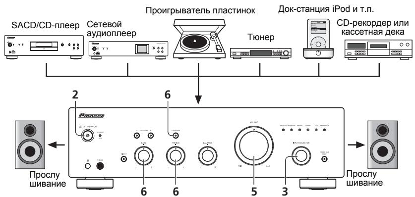
Playback
1 Turn on the power of the playback component.
2 Turn power ON to the unit.
- If the unit is in the standby mode, press the remote control's STANDBY/ON button.

3 Select the source you want to playback.
Select the playback component.
- When using the A-30's remote control, the INPUT +/- button can be used to select the component.
- When using the front panel controls, rotate the INPUT SELECTOR knob.
4 Start playback of the component you selected in step 1.
5 Adjust playback volume with VOLUME control.

6 Adjust the tone to your preference using the BASS and TREBLE controls, and LOUDNESS button.
If the DIRECT button has been set to ON, these controls are disabled.
Set the power to Standby
1 Press the remote control's STANDBY/ON button.

The next time you wish to turn on the power, press the remote control's STANDBY/ON button.
- In the case of the A-30/A-20, if the front panel's STANDBY/ON button is pressed, the power will be turned off. In this case, if the power is off, pressing the remote control's STANDBY/ON button will not turn on the power. To turn on the power again, press the front panel's STANDBY/ON button.

Note
- If the power cord is disconnected when the unit is in the standby mode the unit will turn off, but when the cord is then reconnected, the unit will not automatically turn on. After reconnecting the power cord, press the remote control's
STANDBY/ON button to turn the power on.
When using the unit as a power amplifier (A-30 only)
When a pre-amplifier is connected to the unit's POWER AMP DIRECT terminals, the unit can be used as a power amplifier.
1 Press the POWER AMP DIRECT button on the front panel of the unit.
The POWER AMP DIRECT indicator will light.

Caution
- When the POWER AMP DIRECT indicator is lighted, operations change as follows:
- The unit's front-panel VOLUME, BASS, TREBLE and BALANCE controls are disabled. These adjustments are controlled by the component connected to the unit's POWER AMP DIRECT terminals.
-
When the POWER AMP DIRECT indicator is lighted, sound volume from the A-30 will automatically be fixed at its maximum output. When using this unit as a power amplifier, check the output level of the component connected to the POWER AMP DIRECT terminals and set it to a low level as appropriate before turning on the POWER AMP DIRECT indicator. If the sound volume of the component connected to the POWER AMP DIRECT terminals is initially set to a high output level, loud sound may suddenly be output when the POWER AMP DIRECT indicator lights.
Sound is not produced from the PHONES jack and REORDER OUT terminals. -
For more information, consult the operating instructions for the component connected to the A-30's POWER AMP DIRECT terminals.
Making an audio recording
You can make an audio recording from any audio source connected to the amplifier.
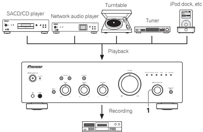
Audio recording component (CD recorder, tape deck, etc.)
1 Select the source you want to record.
2 Start recording, then start playback of the source component.
To set for automatic standby status (Auto Power Down)
When this condition is set, if no input signal is detected for 30 minutes, the unit will automatically enter standby status.
1 If the unit's power is ON, hold the unit's front-panel DIRECT button and LOUDNESS button depressed simultaneously for three seconds.
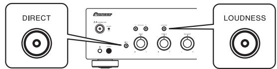
When this condition is set to ON, the STANDBY/APD indicator on the unit's front panel will light green. Press the buttons again to disable the setting.
This condition can also be set by means of the APD button on the A-30's remote control.
The factory default setting is ON.

Note
- Depending on the device connected, excessive noise produced by the device may be interpreted as an audio signal, thus preventing the Automatic Power-Down function from operating.
Restoring all the settings to the factory default settings
1 When power is in standby mode, hold the front-panel's DIRECT button and SPEAKERS A button depressed simultaneously for five seconds.
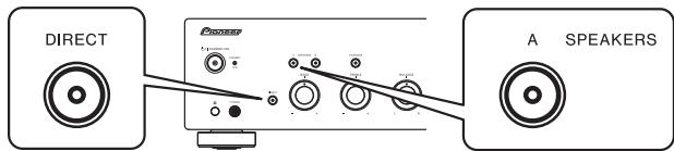
2 Turn power ON to the unit.
Chapter 5:
Additional information
Troubleshooting
Incorrect operations are often mistaken for trouble and malfunctions. If you think that there is something wrong with this component, check the points below. Sometimes the trouble may lie in another component. Investigate the other components and electrical appliances being used. If the trouble cannot be rectified even after exercising the checks listed below, ask your nearest Pioneer authorized service center or your dealer to carry out repair work.
- If the unit does not operate normally due to external effects such as static electricity disconnect the power plug from the outlet and insert again to return to normal operating conditions.
| Problem | Remedy |
| The power does not turn on. | ·Is the power plug disconnected from the power outlet? Connect the power plug correctly to its outlet (page 6). ·Is the power cord disconnected from the AC IN connector? Connect the power cord correctly (page 6). |
| Power turns off. | ·Is the Auto Power Down function turned ON? If you do not want the power to turn off automatically, disable the Auto Power Down function (page 11). |
| During playback, sound stops, and the STANDBY/APD indicator flashes red at about 1 second intervals. | ·The unit's internal temperature has risen and the safety circuit has operated. - Turn power OFF, and allow the unit to cool before turning the power ON again. - Install the unit in a location with better ventilation. - Confirm that the unit is installed correctly, if the unit is turned on again without being allowed to cool, the same symptoms may appear (page 4). |
| During playback, sound stops, and the STANDBY/APD indicator flashes red at about 2 second intervals. | ·Are you using speakers with impedance values not supported by this unit? Confirm the speaker's nominal impedance value (page 6). ·Are any speaker cables loose from the SPEAKERS terminals and touching other wires or the surface of the rear panel? Disconnect the power cord and reconnect the speaker cables correctly (page 6). |
| When power is turned on, the STANDBY/APD indicator flashes at irregular intervals. | ·The unit's circuitry is damaged. Disconnect the power cord and consult your dealer or nearest Pioneer authorized service center. |
| No sound is output when a function is selected. | ·A connection cable is disconnected or connected improperly. Check your connections (page 5). ·Connectors or pin plugs on a cable are dirty. Wipe off any dirt from connectors and pin plugs. ·Confirm that the unit's input selector is set to the desired playback component. Set selector correctly (page 10). ·In the case of the A-30/A-20, press MUTE on the remote control to turn muted off (page 9). |
| No sound from one speaker. | ·Are the connection cables or speaker cables disconnected on one side? Reconnect securely (page 5). |
| Problem | Remedy |
| Can't operate the remote control. | •Replace the battery (page 4). •Operate within 7 m, 30° of the remote sensor on the front panel (page 4). •Remove the obstacle or operate from another position. •Avoid exposing the remote sensor on the front panel to direct light. •Is the control cord for one component connected improperly? Confirm correct connections (page 6). |
| Can't change input source on A-30. | •Check whether POWER AMP DIRECT function is ON. If so, press the front panel's POWER AMP DIRECT button to turn the function OFF (page 10). |
Cleaning the unit
- Use a polishing cloth or dry cloth to wipe off dust and dirt.
- When the surface is dirty, wipe with a soft cloth dipped in some neutral cleanser diluted five or six times with water, and wrung out well, and then wipe again with a dry cloth. Do not use furniture wax or cleansers.
- Never use thinners, benzine, insecticide sprays or other chemicals on or near this unit, since these will corrode the surface.
Specifications
Amplifier section
Power output specification is for when power supply is 230V
Continuous power output (both channels driven at 20Hz to 20kHz
A-30 .70W+70W
A-20,A-10 .50W+50W
(THD 0.1%, 4 Ω)
A-30 40W+40W
A-20,A-10 30W+30W
(THD 0.05%, 8 Ω)
Audio section
Input (Sensitivity/Impedance)
SACD/CD, NETWORK, TUNER, AUX, REORDER 200 mV/50 kΩ
POWER AMP DIRECT (A-30 only). 1 V/10 kΩ
PHONO (MM) 2.8 mV/50 kΩ
Output (Level/Impedance)
RECORDER OUT .200 mV/2.2 kΩ
PHONES 250 mV/32 Ω
Frequency response
SACD/CD, NETWORK, TUNER, AUX, REORDER .5 Hz to 100 kHz +03 dB PHONO (MM). .20 Hz to 20 kHz ±0.5 dB
- Measured with DIRECT button switched on.
- Tone control
(When VOLUME is set to -30dB
Bass. ± 10 dB (100 Hz)
Treble. ± 10 dB (10 kHz)
Signal-to-Noise Ratio (IHF SHORTED, A-NETWORK)
SACD/CD, NETWORK, TUNER, AUX, REORDER
105 dB*
PHONO (MM, 2.8 mV input) 77 dB*
- Measured with DIRECT button switched on.
- Speaker load impedance
A,B 4Ωto16Ω
A+B. 8Ωto32Ω
Bi-wiring 4 Ω to 16 Ω
Miscellaneous
Power requirements
AC 220 V to 230 V, 50 Hz
Power consumption
A-30 175W
A-20/A-10. 135 W
In standby. 0.3 W
Dimensions
435 mm (W) x 128 mm (H) x 360 mm (D)
Weight (without package)
A-30 7.9 kg
A-20 7.2 kg
A-10 6.7 kg
Accessories
Remote control (Except A-10) 1
AAA/IEC R03 dry cell batteries (Except A-10) 2
Power cord
Warranty card
Operating instructions (This document)

Note
- Specifications and the design are subject to possible modifications without notice, due to improvements.
Corporation and product names mentioned herein are trademarks or registered trademarks of the respective corporations.
IMPORTANT

A propos de "bi-câblage (bi-wiring)"
14 Bouton/indicateur POWER AMP DIRECT (A-30 unquipment)
© 2012 PIONEER CORPORATION.
3 Pulsante/spia SPEAKERS A
10 Pulsante/spia SPEAKERS A
A-30 .70 W + 70 W
A-20,A-10 .50 W + 50 W (THD 0.1% ,4Ω)
A-30 .40 W + 40 W
A-20,A-10 .30 W + 30 W (THD 0.05% ,8Ω)
Sezione audio
- Ingresso (sensibilità/impedenza)
SACD/CD, NETWORK, TUNER, AUX, RECORDER 200 mV/50 kΩ
POWER AMP DIRECT (solo A-30) 1 V/10 kΩ
PHONO (MM) 2.8 mV/50 kΩ - Uscita (livello/impedenza)
RECORDER OUT 200 mV/2,2 kΩ
PHONES 250 mV/32 Ω
Risosta in frequenza SACD/CD, NETWORK, TUNER, AUX, REORDER Da 5 Hz a 100 kHz ^± 0_-3 dB* PHONO (MM). Da 20 Hz a 20 kHz ± 0,5 dB* Misurato con il tasto DIRECT acceso. - Comando di tonalità (Quando VOLUME è impostato su -30 dB)
Bassi ± 10 dB (100 Hz)
Alti ± 10 dB (10 kHz)
Rapporto disturbi (IHF IN CORTO, RETE-A)
SACD/CD, NETWORK, TUNER, AUX, RECORDER 105 dB
PHONO (MM, ingresso da 2.8 mV) 77 dB - Misurato con il tasto DIRECT acceso.
Impedenza del carico dell'altoparlante A,B Da 4Ω a 16Ω A+B. Da 8Ω a 32Ω Biwiring. Da 4Ω a 16Ω
Varie
Requisiti di potenza AC da 220 V a 230 V,50 Hz Consumo energetico A-30 .175 W A-20/A-10 .135 W In standby .0.3 W Dimensioni .435 mm (L) x 128 mm (H) x 360 mm (P) Peso (senza imballaggio) A-30 .7,9 kg A-20 .7,2 kg A-10 .6,7 kg
Accessori
© 2012 PIONEER CORPORATION.
WAARSCHUWING NETSNOER
2 STANDBY/APD-indicator
A-30 .70 W + 70 W
A-20,A-10 .50 W + 50 W (THD 0,1%,4Ω)
A-30 .40 W + 40 W
A-20,A-10 .30 W + 30 W (THD 0.05%,8Ω)
Audiopedelte
He yctanabnBaIte n3dene B nloxo
PpOBeTpNBaEMOM NOMEUeHIN INN B MeCTe C BbICOKOJ
BlaXHOCTbIO,OTKpbITOMIJI pIpyMOrO COHHeuHOrO
CBeTa (IIN CNJIbHORO NCKYCCTBEHHORO CBeTa).
D3-4-2-1-7c*A1Ru
EcnBnIka shHypa nItaHnI n3dJIeNHe
COOTBeTCTByeI NMeIoUeIcRgJIeKtropo3eTKe, BUNKy CLeJeYeT 3aMeHnB Ha NOxOJaIyU K PO3eTKe.
3aMeHa N yCTaHOBKa BUNIKI DOJNXHbI pON3BOIDtBcR TOIbKO KBaJIINΦUINPOBaHHbIM TEXHNKOM.
OTcoeHNHeHHa OT Ka6eBnKa, NpOKnHoueHHa K
pO3eTke,MOxET BbI3BaT TjXKeJIoE IopaxHeHne 3JIeKTPnueckm TOKOM. PocJe ydaJIeHnBUNKn yTuINu3npyTe ee DoJXHbIM o6pa30M.
O6opydoBaHne cIeJyET OTKIIOHaTb OT 3NeKTPoCeTn, n3BNEkA BnIKy Ka6EJI NITAHNIA I3 po3EtKN, ecNI OHO He 6yDet NcNOJIb3OBAtbcra B TeHeHne DoIrTO BpeMeHH (HaNPImep, ecNI Bbl ye3kaete B OTnyCK).
D3-4-2-2-1a_A1_Ru
BHIMAHNE
BbIKHouaTeNb /I STANDBY/ON daHHoro
yctpoiCTBa He nolnoctbIO OTKIIIOUaET erOOT 3NEkTPOCeTI. YTO6bl NOLHOCTbIO OTKIIIOuHTb NNtAHHe yCTPOIcTBa, BbITaUNTe BnIKy Ka6eJIa NNtAHnI N3 3NEkTropo3eTKN. I03TOMy yCTPOIcTB O CNe dyET YCTaHABINBaTb TaK, YTO6bl BNkY Ka6eJIa NNtAHnI MOXHO 6blIO JERKO BbITaUNTb N3 PO3ETKN B Upe3BbUaHbIX O6CTOaTeNbCTbax. Bo n36ExKaHHe NOxapa Cne dyET N3BNEKATb BNkY Ka6eJIa NNtAHnI N3 PO3ETKN, ecNI yCTPOIcTBo He 6bYdET NCNOlb3OBaTbCBy TeHeHne DOnlro BVpeMeHN (HaNPIMep, ecNI Bbl Ye3KaTe B OTnyCK).
D3-4-2-2-2a*A1Ru
Данhoe Иденипраздаимауноьзовань В ошиххоясгвьхця.В clyuae BO3ннбовниюненсравнoctи,CB3aHHOИ C hCNoIb3OBaHem BДpyrnx,HexeJIN XO3ЯСТБЕньхцялax (Takx,KakДInteьhoe ИсNoIb3OBaHne B KOMMepuecknxцяnxВ pectopahENB aBTOMoBnle, HnHa Kopa6JI) n Tpe6yIoUe peMOHTa,TaKoi pemont OcyujectBlaTeTc4a ПaTy,JaXeB TeeuHHe rapaHTHNOHor cPoka.
K041_A1_Ru
MEPbI IPEIOCTOPOXHOCTN IPN OBPAUENC CETEBBIM SHHYPOM
Держпге сеевошнур 3а Влку. He Bытасьвайсь вилку,ВЗЯВиись 3a WHyp,ИнКогда He KacayTeCb ceteberoшнур,ecnB瓦иpyк Влaxньile,Tak кak 3TO MOЖET пивесгки КОКОТКOMY 3amblkaHINIO nIIN nopaxhenIO 3JeKTPnueckm TOkOM. He CTabbTe annapat,праздметы мeбели n.T.D. Na CeteBOI shHyp, He 3aximmaite erO. He 3abryBaBAITE y3IOB ha shHype n He CBzryBaIte erO cdpyHMn SHypAMN. CeteBbIe shHypbIdoJIxHbI JekaTb TAK,чTOБы Ha HIX HeNb3Я 6bINo HAcTyNtB. ПOBpeXdENHbI CeteBOI shHyp MOЖET cTaTb prUnHoi BO3NHKHOBEHЯ NOJapa nIIN npa3ntb Bac 3NeKTPnueckm TOKOM. Bpemr ot BpemeHnpOBepraIte ceteBOI WHyp. B cnyuae obHapuyKeHnIA NobpeKdEHHa ObaPITcB 3a ZAMHoB B 6lnkaWIIOn OphiuaJIbHbI cepBnCHbI ceHTp Фпмы PIONEER nIIn K BaUeMy dIJIepy.
S002*A1Ru
PENDyIPEKeJDEHNE
Bo n36exkane noxkapa He np6nkaite K o6opydoBaHIO nCTOCHNI OTKpbIToro ORHr
(Hanpimep,3axkkeHHbIe CBeuN).
D3-4-2-1-7a_A1_Ru
(TOJIbKOДЛЯМоDEЛN A-30)

ПЕДОCTЕРЖЕнUE: ГорячА NOBEPXHOCTb. HE ПИКACAITECb.
BepxHra nOBepxHoCTb paDnAtopa MoKet HarpeTbCpI npIpoDOnJXnteJIbHOM IcNoIb3OBAHN DaHHoro N3dEJIa.
01 Pered nauanom pa6oTbI
KoIIeKtaIa. 4
YcTaHOBka 6aTapeeK B IyIbT Dv
(Кроме модень A-10) 4
HnOIOI3OBAHNE PnyIbTa NIOCTAHINHOHORO ynpabJIeHHN 4
UcTaHOBka yCHJIInTeJIa 4
02 Podknoyehne
IIOJIIOUeHHe Ka6eJIeI 5
O“BbYxIPOBOJHOM COeINHeHHN” 5
IIokluohne ka6eJIe AC 6
IIOKJIIOUeHHe ayIOHOka6eJe. 6
HIOJIb3OBAHHe IeHTpaJIH3OBAHHOro yIpaBJIeHNc IIOMOJIbIO npYrHx KOMIOHEHTOB Pioneer
(КрOME модали A-10) 6
IIokluohene KJIeKtpnueckoCtH 6
03 OpraHbI ynpaBnEnHa INHdkaTOpbl
Ipeenra IaHeJIb 7
3aHnaHeJIb 8
IyIbT IY (KpOMe MoJeJIH A-10) 9
04 Θκπληγαταίη
IIpocIyIHHBaHHe 10
IpekeJIOueHHe yCHJIHTeJI BpeKHM OKeJHaHHa.10
HcIOJIb3OBAHHe yChJIHTeJI B KaueCTBe yChJIHTeJI MoIHOCTH (TOJIbKO IJIA MOJeIIH A-30) 10
3aIINsb ayIIO cnHnla
(Ha BHeIiHee 3aIIncbIbAIOIIee ycTpoIcTBO) .11
AKTHBaunH yHKHH ABTomaHTueckoro
Ipepxoia BpeKIM OxHnHaHH
(aBTOMaTHueCKOTo BbIKJIHOeHHN) 11
BocctaHOBJeHHe 3aBOJCKHX HAcTpoek .11
05DOnOHnHTeNbHaNnHΦopMaun
YctpaHHe HEnCnPaBHoCTei. 12
UHCTka yctpoiCTBa 12
TexHHueckHe xapaKTepeHCTKN 13
IcnoB3ObaHne npbTa nctaHnOHHO
UnpaBJeHna
IyIbT IINCTaIHIOHHOYIpyABJIeHHN HmEt dJIbHoCTb DeICTBnO KOIO 7 M pH yIgE OTKIOHeHHN O t cEHcopa 30^
YctpoictBO HyKHO yCTaHOBHTb Ha POBHyo H yCTOHNOBEPXHOCTb.
He yctanabIINBAITE eroB CJIeDyUOuHMe cMeTA- Ha TeJIeBn3Op (3TO MOKET BbI3BaTb HcKaJKeHHc H3O6paKeHHa)
-Bo3JI KaccetTHOJLeKN (HIN B6IHN3YcTPOHCTBA, rerehpnyioero MaHHTHOe POJIe).TO MOKET Bb3BATb HsCKAKeHHe 3yBuKa.
- Ha IIpyMbIX COJIHeUHbIX JIyax
-B CbIPbIX H BJIaJXHbIX MecTAX
B Yupe3MepHO XOIOIbIX HJIN TOpRyHX MeCTaX
-B MECTAX, IJDE HMEET MECTO BVHbpaiaa HIN JpyTOE DBIKENHE
-BOeHbIbJIbHBIX MECTAX
B-MECTAX,JIPEHCYTCTBYOTOPRHYE HCNAPENHHIHN MACHA(HANPHMEK,HA KXUYE)
He yctahabIbHae TaHHoe yctpoCTBO Ha IINBaH INIpyTOIpeIMet HmMATEpHnAICNFOJIIOaIOIHMH CBOIChBAMH, TAK KAc 3TO MoKTe He6JaToPiPrTHO NOIBHtHa KaueCTBO 3Byka.
TJaba2:
Поклоченье
PoiKJIIOUeHne Ka6eJIeI

OctopoxHo
- IIpeJke, Yem IpoH3BOOHTb KaKHe-JIHOIOKJIIOHcEHHa, BbIKIOOHte IITaHHe N OTKIOOHte CeTeBOI HYP oT p03eTKH.
-ПлдкшаьКабьltнганьКЗIEKtpHueckoiPo3eTkeCJIeIyETIOcJIeBbIIIOJIHeHHNcoEINHeHHMeKJyBCEMH yctpoHCTBAHM.

Octo3poxHo
KJIeMma SIGNAL GND (3a3eMJIeHHe cHrHaJa) IpeIHa3aHcHEnI DII CHNKeHHy UypOBH IIUMOB IIPIIIOJIHOueHHYcHITJIeT K TAKMH YcTOPOCTBAM,KAIPIOHPRTbBAteJIb BHNHIJOLBXI IIaCTHNOK.
He cIeJeYerIOJIKIOHATb KBXOy PHONO (MM)
KAKHe-ILHO yCTPOHCTBA,KPOMe IPOHPBtBaTeJI
BHINIOBbIX IIaCTHHoK.TaKKe He cIeJeYer
IOJIKIOHATb K 3OTMy BXOy IPOHPBtBaTeJI,
OCHaueHHb BCTPOEHnMb 3KBaJIaIIePOM.3To MOKeT JPNBEcTH N KBIOy 3BvKa C Upe3MePHo BIVCOKHM yPOBHeM rPoMKoCTn H Bpe3yIbTaTe -IOpBeJdeHHo AC HIN dpyrIcx TcPOHCTB.
BxODPHONO (MM) ycnHHTeJI ppeHa3aHueen IJIIOKJIOUENHHIPOHPTbATEJIeO,ochaHEHbIXTOILOBKOB 3BkyKOCHMATEJIc CIOBHKBbHM MAtHNTOM(MM).He cJIeYET KJIOHNOATb IPOHPTbATEJI,OCHAHEHbIE TOILOBKOB 3BkyKOCHMATEJIc CIOBbHKHOI KATyIKoM (MC).
He npereH6aIte Ka6eJIIN NIOBepx yctpoIcTbA (KaK Ioka3aHO HA IIIOHcOtpaIHH).B 30m cIyae co3daBaEMOE TpaHcΦopMatOpAMn yctpoIcTBA 3IKeKpOMaHIHTHOIe MOKeT Bb3BaTbΦOHOBH bIM Y B INAHMkAAC.
K BxOyU POWER AMP DIRECT cyuHntTe He cIeJeTIOKIIHOaTbkKe-1b0BbXoBb, KpOme bXoDa PRE-AMP OUT (BxOJIOpeCyHnTeT).
Ecn y Baunero npoHrpBbateIe bc7 3a3eMJIHOIIINI pOBOJIOKJIOHNOHTe E0 K 3a3eMJIHOIIeK JcEMMe ycNJITTEJ.

Примechане
-Пин ПОДКИОЧЕНС KACCEТHоД ДЕКИ мОERT bIbT cIbIshEN IYIM BOCIPINOBDEHIN,В 3BABCHMOCHT ON MecTA yCTAHOBKH.3OT YIM mOERT bIbIBAH NOTOKOM paccseHnO rT pAncfoMpAToPA yCJIHITeJI.B 3OM CJIyUaYe yCTAHOBHte yCJIHITeJI B.IpyTOm MecTe HII INIpeMeCTHrde KeY Ha 6OJIbIeE paCCtOHHe OY CJIHITeJI.
- iPod Альперета Товарьим 3нakом KMПаннн Apple Inc., Зерпсгтphpоварьим B СИАн И дугх страх.
O "DByxnpoBOqHOM coeINHeHH"
ДаньусиHTeJIb moKHO hCIOJIb3ObaTb c AC, IIOJIepKHeBaOIIHmI DByXIIpoBOJHoe COeJIHHeHne. Heo6xOJHMo IOIcoEJIHHb Ka6JIeHN H3K0UaCTOTbIx H bICOKOCACTOTbIX ChnHaJIOB COOTBeTCTBYIOHM 6op3OM.
- Bo Bpemr IpoClyuHbAHnKhoIKN SPEAKERS A (AkyctHueckne CnCTeMbI A) n SPEAKERS B (AkyctHueckne CnCTeMbI B)doJIKnHb HaxoIHTbcB a noIOJKeHHN (BkII.1), ctp. 7.

OctopoxHo
IpnHcNoJIb3OBaHHn DByXIPoBOHOrO cOeJIHNHeHNA ECIO6xoJIMHO ydaJIHTIbepeMboYHK n KJIEMMHIGH》(B)H<LOW》(H)AAC JDAIINPEIOITRAPUeHHN He6IaIopnPIHTHO R03JIeICTBnHa cyJIHTeJIb.IIOpO6HbIe CBeJIENm CB.N HbCTpyKuIIHX, BXOJIHIX B COMJIIEKT NIOCTBAK IC.
- IIPIH HcIOJIb3OBAHH AC cOTKJIHOaEMbIMH pA3JIeJIteJIbHMn fHbIbTPAMn IOMNHTE, TTO eJIH fHbIbTp OTKJIIOueH, 3dffeKT 6ydtETCytCTBOBAT h MOKET IIPOIH3OH NOBpeJKeHNE AC.
Takke MoKHO IIOJKIOHHTIPOBOJa OT KJIEMM SPEAKERS A (AkyCTHueCkHe CnCTeMb IA) K KJIEMMAM «HIGH» (BU), a OT KJIEMM SPEAKERS B (AkyCTHueCkHe CnCTeMb IB) - K JIEMMAM «LOW» (H4) (ipOTHBOIOJIOXHM o6pa3OM TOM, KaK IOKa3aHo Ha pHCyHKe).
IopknHouHenkeKabene AC
1 CkpyTte Xnbl npoBODKa6eJIA.
2 Ocna6bTe raKy KEmMbI SPEAKERS (AkyCTnueckne CnCTembl) N BCTaBbTe npoBOD AC B OTKpbIBWeecr OTBepTne B wTbIpe KEmMbI.
3aTAHHTe raKy KJIeMMbl.
2

Octopokho
- Pn INcNoB3OBoAHIn TOJbKO OndHoro Habopa KIeMM AC SPEAKERS A (AkyctNueckne CnCTeMb A)/SPEAKERS B (AkyctNueckne CnCTeMb B) INn pRn INcNoB3OBoAHn DByxnpoBDhIX CoedHEnHm AkcyTneckne CnCTeMb DOnjXhbl IMeTB HOMHaJIbHOe CONpOTNbEHe N BdnaIa3OHe 04 Ω do 16 Ω. Pn INcNoB3OBoAHn DByx HApobOB KIeMM AC DOJXhbl IMeTB HOMHaJIbHOe CONpOTNbEHe N DnIa3OHe 08 Ω do 32 Ω. CBeDeHn O HOMHaJIbHOm CONpOTNbEHN CM. B INhCTpyKuINx No kcnlnyatauIN AC.
Плбжгдьнгсиоу STNRIATeJIbHmKJIeMMbI (+/-) NauchЛHTeДоJIKHbI b6tIb coeINHeHbI ccoOTBcETbYIOUHMKJIeMMMAMHnA HC.
Ha KJIEMMAX JIJI NOJIKIOHEnA kYCTNueCKOCHCTeMbI HmEeTcONAOHEДJI KUN3HNHANPKeHHe.Bo NT6BeKaHIne NopAKHe 3JIeKTPnueckHM TOKOM IPIH IOJIOCoEINHeHH INOTCOOEINHeHH IPOBOD AC OTcoEINHITRE Ka6eJIbTIaHHa, IpeKeJe CEm PnHKoCHyTBcK KaKHM-JIb60HEN3OJIPOBAHBBM DTeJIAM.
BceKJIbI OJIoJIeHHOrIO IpOBoJaIOJIJKHb6blTb CkpyueHb, a IPOBOJ OJIoJIeKb6blTb POJIHOCTbO BCTaJIeB H KJIeMcy AC.EcII KAKOI-JIb6 OJIOJIeHHb IPOBOAC 6bETKaCtBa3aIHeiPiAEJI,MOKet cpaOToBt 3aIHTHb BbIKJIOUOATEJI bIHTAHIN.
PoiKJIuChHe aynokabeJe
IIOcoeDHHTE 6JIJI tKeK R H3E3y JEBORO KAHAJA (L), a Kacshn I tKeK - K H3E3y npABORO KAHAJA (R). IIItKeKbI OJIKHb6BtIb IOJIIOCTbO BCTABJIEM b R H3E3a.

IcnoJIb3OBAHnE cHTpaII3OBAHHoro ynpaBHeHnC nOMoUbIO pyrNk KompoHENTOB Pioneer (Kpome moJen A-10)
K ychJIHTeIIO MoJIeJIH A-30 HJIN A-20 MOJHO IOJIJKIIIOUaTH bAJIYNHbE KOMIOHEHTb PioneER, OCHIaeHHeBIE THe3dAM CONTROL IN/OUT (BXoI H bXoI YIpaJIeHn), YTO IOIIOBJeIeHTpAJIIO3OBAHNO YIpaJIbTIy KOMIOHEHTAMN IocpeIcTBOM pIphEMHHKa DY na cYchJIHTeJIeMOJIeHn A-30 HJIN A-20. BlaOJApAR 3OTMy MOKHO TAKKe IcCTaHIOnHO YIpaJIbTIb YcPoJIcTBAmH, HE OCHaJIeHHbIM pIphEMHHKOM DY HJIN yctAHOBIEHHbIM B MecTax, rIe pIphEMHHk D KOMIOHEHTHa HeIOCTuYHn.

PpMueaHne
Ди IOДКЛIOHUEHIN yCTPOI8CT HCSIOJIb3yIHe HMEIOUIHecB I PpOdaJMe KOHOJOHNIEcKHe Kae6JIeH C MHHIIITTEKEPAMH (6e3 pe3HcToppa).
PnPiIOJIKJIOHcENHHyCTPOHCTB K THe3dAM CONTROL IN/OUT (BXoI H BYXoI YpnpABJIeHNH) HeO6xoJIMHO TaKae HCIOJIb3OaBT HMeIOUHNEB I npOJaKe ayIbIOKa6EiN JIAAHOJORBOxH CoeIHNEHN. PIOJIIOHcHHe ToIbKO C HIOJIb3OBAHEm THe3D CONTROL IN/OUT (BXoI H BYXoI YpnpABJIeHNH) He 6oeCIEeHT Bo3MOKHOCTb HaJIeKaIeO ynpABJIeHNH cHCTeMoI.
EciN KaBefIy npuBaJIeHHIOIooeiHHK rHc3yD CONTROL IN (BxOJ npuBaJIeHH) yChIHTeJIy moJIeA-30 HnA-20,BeHOzMOHooY npuBaJIbTb YCNHTeJIeM,HaNPaBB NpIbT DY HaCyHInTeJIb MOJIeA-30 HnA-20 (PnHemNK Dy ABTOmatHueckn OTKIIuOaETC).
PoiKJIuOHeHne K 3JIeKTpIuYeCKoCetn

BHHMaHne
OTnpabIaBbIy B IyTeIEeCTBHe IINIO KAKoJI-NIb6HOHIO PPnHHe IIaHpy He HcNOIb3ObAt yChJIteB I TeUeHNHe IInITeBbHOrO BpeMeH, BCJTa OToKIOuHTe KaBeIb IIITAHNo ITOEKTPhueCKoPozETKn. PIIpMaehueA: PAaJIHHe BByTupHeHn HAcPOrKe H 6yDyt UdJeHb,IaKe eCIN KaBeIb IIITAHNo 6yDyt OTkIOuHeNOT EIKTPhueCKoPozETKn B TeUeHNHe IINITeBbHOrO BpeMeH.
EJIIN HeO6OJHMOI OTKJOUOHIT KaJEb IINTAHINOT 3JIeKTpHueCKoB PO3ETKN, CHaJAA YIOCTOBpeTcB, TTO HIXAKATA KHOIIKA O/ISTANDBY/ON (CtB- TeKHM OJHKDAHN/BLK) Na IpeJdHn PAHeIN yCNHIITEJI, YTOb6 YCJHNTJIteM oMeJIHn A-30 HNn A-20 6bl BbIKJIIOUeH, a cHyJIteJIb MoJeHn A-10 IpeJIeH n B pEKHM OJHKDAHN, H ToJIbKO IOCE J3TO rO tKJIOuHaTe KaJEb IIITAHIN.

OctopoxHo
- Икплбоване Кабелгп.TOTORO TO TOTOKBOTY BXOJNT B KOMIIJIeKT NOCTABKN,ПИРБЕТК
ПИЕКРДЕЦHNO RAPTAHN,ТAK KAK COMIIJIAHN PIONEHT HE HECET OBTERTCTBEHNCHT 3A KAKHE-ПИБО NOBPEKDEHINHA,
HAHECEHNEHBY B TOMC LyUAE. (HomHaJIbHoe 3HaIeHne
TOKOBH NAPrty3K KAbELI INITAHAN, BXOJIIMERO B
COMIIJIeKT NOCTABKH MOneIIN H-A-30,CocTBIAJIeT 10 A,a
Kabela IIITAHNIA,ПиЛЯагоMuIeROG K A-20/A-10,
CocTBIAJIeT 2.5 A.)
He cIeIyET HcIOJIb3OaBt bKaoiJiU6 IOHNO Ka6eIb IIHTAHIN, KpOME BxOJaIIeTO B KOMJIeKT IOCTABKN DAHHORO yCTPOIcTBA.
3aIpeHaeTcHIOJIb3OBAbBXOJIAIIH B KOMIIeKTHoCTABKH Ka6EJIbIHITAHINI JI KAKHX-JH60 HINbIXIeJIH, KPOME YK3a3HHbIX HNIXe.
IIOJIe BIIIOJIHIIIE CEXC COOEIIHHIIOIJIHOHHTE YCUHJITJIb K pO3EKe 3JIKETPHYECCKI CET hEPMEHBOHTO KA
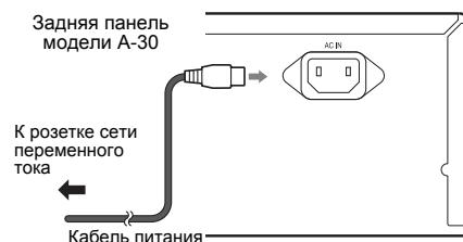
1 Pódklnochite Bxodjün B KOMnJIeKT Ka6enb Ntahmɪ K rHe3y AC IN (Bxod NtAHnInepeMeHHOrO TOK) Ha 3aJHéN naHEn yCunlnteJIA.
2 BctaBbTe 5tTencelbHyu BnIky Bpo3eKty 3JekTpnuueckOn cetn nepemehHoro Toka.
Глaba 3:
OprahbI ynpaBJeHnI n HndIkAtOpbl
Ipeedna naheB
1 KhoNka /I STANDBY/ON (CeTb - PexKIM OxuJaHn/BykJ.)
們 kHIOJI CJIyKHT DJIY BbIKIHOeHHN H KBIIOeHHN YCJHITJIJA.
IIpn BkJIOueHHOM IIHTaHHH IopHT HJINKaTOP IIHTaHHB CEHTpe KHOIIKN.
Ha cnHHTte moIeHN A-10 c NMOUIIO TOTI KHOIIKN OcuIIECTBJIETcTpeBEOJ yCHINTEJI B pekHM OKJIADHn I erO BKIOUHeH.
2 INDkaTop STANDBY/APD (Pekim OxuaHra/abTOBkiuOyeHne)
EcIy uChIHTeJIb haxOHTC T BpeKHMe OxHJdHAn, 3OT HnIKaTOp ROpHT KpAchIM CBtEOM. EcIJ yHKiINr ABOTMATuHECKoR BbIKIOUeHNr (APD) BKIOUeHa, 3OT HnIKaTOp ROpHT 3eJIeHbIM CBTNr (ctp.11).
3 KhoNka C HnDnKaTOpom SPEAKERS A (Akyctnueckne cnCTembl A)
HaKMMTE3Y KHOIIKUYIINPPOCSUYIINBAHINAC, IIOJIKJIIOUeHHbIX KJIEMMAMSEALKERSA(AKcyCTHueCKe HcCTeMbIA).
On (BkJ.): INHINKATOP roRHT. AkyCTHNECKHe cNCTEMbBOcIPOH3BDIT3yKb. (3ByK TAKKe BOcIIPOH3BOIHTCpe3BbIXoL PHONES (HayuHnKN))
Off (BbKJ): HINHkATOP he roPTJ. AKyCTHueCKeH CHTeMbI He BOCPHOH3BOJET 3yK. YcTahOBITE KHOIIKY B 3TO IIOJIeONHe IIPI pOcIyUHBAHH 3ByKa Upe3 HauYHINHK.
4 KhoNka C HnDnKaTOpom SPEAKERS B (AkyCTnueckne CnCTeMbI B)
HaKMMte 37y KhoNkIy IJy npocIyIHHaBHn AC, IIOJIKIIOueHbIX KJIeMMaM SPEAKERS B (AkyctHueckHe cshCTeMb A).
On (BkJ): HNIIHKATOP rOHT. AKyCTHueckne CHCTeMJI BOCIPOH3BOJAT 3ByK. (3BYK TAKKe BOICIOH3BOIHTCpe3 BbIXoON PHONES (HayIHHKN))
Off (BbKl.): HNIIKHATOP he Iorpt. AKCYTHeCKeH CHTeMbI He BOCIOPH3BOJAT 3Bky. UCTAHOBITE KHOINKY B 3TO IIOJIOJEHNIE PII NPOJIUYBAHHN 3BkyA ue3 HauHHNK.
5 KhoNka C nHnKaTOpOM LOUDNESS (AkyCTnueckne cncTeMbI A)
HcnoJIb3yIte 3ry KhoIky Iprn IpocIyIHHBaHH 3Byka HnH3KOJ TpOMKoCTH.
On (BkI). HnHdkATOP rOHT. IpoHcxoJNT yCINHeHNE HnKHHN H BepxHHN 3ByKOBbX bact OIT JyUyHHeHHBOcIPNOHBeDEHHa H N3KOHrPOMKoTH.
Off(BbIKI):HnDnKATOp He roptt.KHOIIKa 06bUHNO DoJIJkHa HAXOINTBcB B3TOM IOJIOKeHHN.
IIpHHHMaTe CnHnHaJIb C nIyTa DY (cTp. 4).
7 The3DO PHONES
TOI H3IO CJIYKHT IJIPOIKJIOUOHeHNAUYIHKNOB.3yKHE BOCIPNOH3BOITTC, cIIH KOHNKA POWER AMP DIRECT (PiPMOeIOKJIOUoHeHNE K yCJIHTeHIO MOIHOCTH) HAXOJDCTB IN POLOKeHHN BKI
8 KhoNka c HnDnKaTOpOM DIRECT (PpRMOe PNOKJIIOUHeHne)
On (BkI.): HnHnKaTOp FopHT. Ecln 37a KhoNka HaxoJntcB NoIOJokHeHH «BkJI.》,38KOBbEs CnHnJIbNoIaOHTcH Na BbXoD HAIpNMyB,06xOIpaIiHNHbIXxCem peryUHPOBKN:BASS (Tem6pHU),TREBLE (Tem6pBQ),BALANCE (BaJAnC), LOUDNESS (ToHOMeHecAuaII). BlaTOJaep 3OTMY DoTHaETcBA BtCOKOTOHoe BocPONIHBeHene 3B2HO OTKIoHuAOTcB 3ce HAcTpoHH,BbIOJIHeHHeIc b NOMoiIbO peryJITopoB BASS (Tem6pHU),TREBLE (Tem6pBQ), BALANCE (BaJAnC) HIN KhoNKn LOUDNESS (ToHOKomHecAuaII).
Off (BbKlI): HNIIHkATOp He roptn. CnHai IpoXoJNT chepe3 pa3INHbIe cxmbI qaTOTHOJ KOPpeKuHH. EcIn HNIIHkATOp He roptn, BO3MOxHO BmIOJIHeHne HAcTPOeK c NMOUBo peYJIaTOpOB BASS (Tem6p HU), TREBLE (Tem6p BU), BALANCE (BaJIaHc) N KhoIKN LOUDNESS (ToHKOMIIeHcaIIHa).
9 PerynlaTop BASS (Tem6p H4)
3OTPeyJIaTOp CUYKNT JIINHACrPOHN TEmoPA HNKHINX 3BYKOBbX qACTo. IeHTpaJIbHO nIOJKeHnE 3TORE peryJIaTOp COOTBETCTByET INIIeHHOH (obSyHInO) AQUX.Ipn NBOPoTe peryJIaTOp BnPABO yCHJIeHne HNKHINX qACTo NOBbIIaTaC; pINp NOBoPte BJIeBO yCHJIeHne HNKHINX qACTo CHNIKAeTCs.
C I N O M O I B H O 3 T O H K H O I N K B K I N O U A E T C R N O T K I N O U A E T C R F YH K I N A B A T O M A T H N E C K O T O B B K I N O U H E H N (cTp.11).
TnaBa 4:
3KcPnyatauia
PpocnyuBbHne
1 BkIIOUHTe NITaHne KOMNoHEHTa, CnIHan cKOTOPOrO 6yDet HcNOnb3OBaTbCra.
2 BkInouTe nItaHne ycInnteJra.
EchinyuchHJIteJIb HaxOJIHTcB vpeKHM OKHJUHINHAHXMHTe HnIbTe IV KhoIKNy STANDBY/ON (PeKHM OKHJDAHNH/BKJ).

3 BbI6epNTe NCTOCHNK, CnHaN C KOTOPOROBblXOTNTBEBOCnpON3BecTN.

Bb6epHTe KOMIOHEnT DIII pOcJIyINBaHHa.
IcnoIb3ObaHne ycInTeJI B KaueCTBe ycInTeJI MOUHOCTN (TolbKO IJI MOnEn A-30)
Bxod (yBCTBNTeJIbHOCTb/CoNPOTnBJIeHne)
SACD/CD, NETWORK, TUNER, AUX, REORDER 200mB / 50k
POWER AMP DIRECT (TOLIbKO JINMOJELN A-30) 1 B/10 kΩ PHONO (MM) 2.8 mB/50 kΩ
- BbIXoIyypOBeHb/conpOTnBJIeHne) RECORDER OUT 200 MB,2,2 KΩ PHONES 250 MB,32 Ω
-ДиANA3OH BOCPON3BedeHnAчaTOT SACD/CD, NETWORK, TUNER, AUX, REORDER 5Пиdo100KПи,+0 _3 nB PHONO (MM) 20Пиdo20КПи, ±0.5 nB
-
H3mepeno npu haKamou kHonke DIRECT.
-
Perúniropobka Temópa (Pfn VOLUME-30 dE)
Hn3KHe qacToTbI 10 b (100 I)
BbCOKHe YactOTbI. ± 10日 (10kT)
- OTHOWeHne CnRHaN-WhM (3aKOpOeHHbI BxOd B4, ypOBeHb WhMa no WkaJe A)
SACD/CD, NETWORK, TUNER, AUX, REORDER 105 dB*
POWERAMP DIRETC PHONO (MM, BXOHOH CNHJAH 2,8 MB) .77 dB*
- H3mepeno npu haKamou kHonke DIRECT.
ConpotBnHeAkyctuYeCKNX CnCTEm A,B 4Ωdo16Ω
A+B. 8Ωdo32Ω
IbByxipOBoHoe coeHHHeHne 4Ωdo16Ω
Почи napametpbI
HannpaeHHe HnTAHn 220Bdo230BnepeMeHHoroToKa,50u
Iotppe6JIeMaMA MoIOHOCTB
A-30. 175BT
A-20/A-10 135 Br
BpeKHeOxHuaHHa 0,3BT
a 435 MM (III) x 128 MM (B) x 360 MM (Γ)
Bec(6e3 yIaKOBKN)
A-30. 7,9 K
A-20. 7,2Kr
A-10. 6,7 kT
PpinaJdxHocTn
IIyIbT IV (KpOMe MoJeJIH A-10) 1
Cuxhe 6atapeiAAA/IEC R03 (KpOme moaen A-10) 2
Ka6eJIb IITAHIN
TapaHTnHbI TaIOH
HnctpykuHHIO KcHIIyatauHH (TOT DOKymeHT)

Приимеанно
B C83Hn CIOCTOHHHbM COBpeHHTBOAHNHE M3JIENH texHHueckne XapaKTepHCTKNH KOHCTpyKIIIN MoryT 6bIb M3MeHNHeB 63 nePdeBaHPteJIbHOr yBEJOMLeHNH.
- YIOMHHaEMbIe B HACTOIIeM JOKyMeHTe Ha3BaHHaN KOpnapaui N H3JIeIN YBIAJOTc TOBAPHbIMN 3HaKAMNH IIN 3aPeIrCTprPbOAHbIMN TOBABHbIMN 3HaKaAMn COOTBETCTBHyOuIHX KOpnapaui.
Примechanical:
B COOTBCTBM co CTbE 5 3aKaONa PocnckoΦeepaun "O 3aunite npab notpebnte" n YkaaHnEM IpaNTbCTBa PocnckoΦeepaun N 720 ot 16 noHa 1997 roda kopnpauia Pioneer Europe NV yctahabnaMaT yCNOBE na cIeDyUOyI npdoOpknTebHOCT cbpoka cnYkbl oPhiuaNbHO noctabnEmbx Ha Pocsnckn pbIHOK TOBAPOB.
Aydno n BvdeooobopyoBaHne: 7 let
Ipehenochoe aydnooobopydobaHne:6 let
Друго оборудане (Hayшнки, Мкрфони T.D.): 5 lat
ABTomo6nIbHa 3JNeKtpOnHka:6JeT
D3-7-10-6_A1_Ru
PIONEER CORPORATION, 2012
Bce npaba 3aunuiehbl.
Discover the benefits of registering your product online at http://www.pioneer.co.uk (or http://www.pioneer.eu).
Ummnoptep: OOO "TMOHEP PUC"
125040, Poccsia, r. MockBa, yn. PpaBdbI, d.26 TeI.: +7(495) 956-89-01
PIONEER ELECTRONICS (USA) INC.
P.O. BOX 1540, Long Beach, California 90801-1540, U.S.A. TEL: (800) 421-1404
PIONEER ELECTRONICS OF CANADA, INC.
340 Ferrier Street, Unit 2, Markham, Ontario L3R 2Z5, Canada TEL: 1-877-283-5901, 905-479-4411
PIONEER EUROPE NV
Haven 1087, Keetberglaan 1, B-9120 Melsele, Belgium TEL: 03/570.05.11
PIONEER ELECTRONICS ASIACENTRE PTE. LTD.
253 Alexandra Road, #04-01, Singapore 159936 TEL: 65-6472-7555
PIONEER ELECTRONICS AUSTRALIA PTY. LTD.
5 Arco Lane, Heatherton, Victoria, 3202, Australia, TEL: (03) 9586-6300
PIONEER ELECTRONICS DE MEXICO S.A. DE C.V.
Blvd.Manuel Avila Camacho 138 10 piso Col.Lomas de Chapultepec, Mexico, D.F. 11000 TEL: 55-9178-4270
K002_B4_Ru
© 2012 PIONEER CORPORATION.
All rights reserved.
© 2012 PIONEER CORPORATION.

- CAUTION
- CAUTION:
- European model only
- Information for users on collection and disposal of old equipment and used batteries
- WARNING
- VENTILATION CAUTION
- Operating Environment
- POWER-CORD CAUTION
- (A-30 only)
- CAUTION: HOT SURFACE. DO NOT TOUCH.
- Contents
- Before you start
- Connecting up
- Controls and displays
- Operation
- Additional information
- Chapter 1:
- Before you start
- What's in the box
- Note
- Loading the batteries in the remote control (Except A-10)
- Open the rear lid.
- Insert the new batteries, matching the polarities as indicated inside the case.
- Close the rear lid.
- Using the remote control
- Installing the amplifier
- Chapter 2:
- Connecting up
- Making cable connections
- About "Bi-wiring"
- Connecting speaker cables
- Connecting audio cables
- Using centralized control with other Pioneer components (Except A-10)
- Plugging in
- Important
- Chapter 3:
- Controls and displays
- Front panel
- /STANDBY/ON
- STANDBY/APD indicator
- SPEAKERS A button/indicator
- SPEAKERS B button/indicator
- LOUDNESS button/indicator
- Remote sensor (Except A-10)
- PHONES jack
- DIRECT button/indicator
- BASS tone control
- TREBLE tone control
- BALANCE control
- VOLUME control
- INPUT SELECTOR knob/indicators
- POWER AMP DIRECT button/indicator (A-30 only)
- Rear panel
- Remote control (Except A-10)
- STANDBY/ON
- Input selector buttons
- SACD PLAYER control buttons
- NETWORK AUDIO PLAYER control buttons
- LOUDNESS
- MUTE
- DIRECT
- DIMMER
- INPUT + / -
- SPEAKERS A button/indicator
- SPEAKERS B button/indicator
- VOLUME + / -
- APD
- Chapter 4:
- Operation
- Set the power to Standby
- When using the unit as a power amplifier (A-30 only)
- Press the POWER AMP DIRECT button on the front panel of the unit.
- Making an audio recording
- To set for automatic standby status (Auto Power Down)
- Restoring all the settings to the factory default settings
- Chapter 5:
- Additional information
- Troubleshooting
- Cleaning the unit
- Specifications
- Amplifier section
- Continuous power output (both channels driven at 20Hz to 20kHz
- Audio section
- Input (Sensitivity/Impedance)
- Output (Level/Impedance)
- Frequency response
- - Tone control
- (When VOLUME is set to -30dB
- Signal-to-Noise Ratio (IHF SHORTED, A-NETWORK)
- - Speaker load impedance
- Miscellaneous
- Accessories
- A propos de "bi-câblage (bi-wiring)"
- Bouton/indicateur POWER AMP DIRECT (A-30 unquipment)
- Pulsante/spia SPEAKERS A
- Pulsante/spia SPEAKERS A
- Sezione audio
- Varie
- Accessori
- WAARSCHUWING NETSNOER
- STANDBY/APD-indicator
- Audiopedelte
- BHIMAHNE
- MEPbI IPEIOCTOPOXHOCTN IPN OBPAUENC CETEBBIM SHHYPOM
- PENDyIPEKeJDEHNE
- ПЕДОCTЕРЖЕнUE: ГорячА NOBEPXHOCTb. HE ПИКACAITECb.
- Pered nauanom pa6oTbI
- Podknoyehne
- OpraHbI ynpaBnEnHa INHdkaTOpbl
- Θκπληγαταίη
- 05DOnOHnHTeNbHaNnHΦopMaun
- IcnoB3ObaHne npbTa nctaHnOHHO
- UnpaBJeHna
- TJaba2:
- Поклоченье
- PoiKJIIOUeHne Ka6eJIeI
- OctopoxHo
- Octo3poxHo
- Примechане
- O "DByxnpoBOqHOM coeINHeHH"
- IopknHouHenkeKabene AC
- Octopokho
- PoiKJIuChHe aynokabeJe
- IcnoJIb3OBAHnE cHTpaII3OBAHHoro ynpaBHeHnC nOMoUbIO pyrNk KompoHENTOB Pioneer (Kpome moJen A-10)
- PpMueaHne
- PoiKJIuOHeHne K 3JIeKTpIuYeCKoCetn
- BHHMaHne
- Глaba 3:
- OprahbI ynpaBJeHnI n HndIkAtOpbl
- Ipeedna naheB
- KhoNka /I STANDBY/ON (CeTb - PexKIM OxuJaHn/BykJ.)
- INDkaTop STANDBY/APD (Pekim OxuaHra/abTOBkiuOyeHne)
- KhoNka C HnDnKaTOpom SPEAKERS A (Akyctnueckne cnCTembl A)
- KhoNka C HnDnKaTOpom SPEAKERS B (AkyCTnueckne CnCTeMbI B)
- KhoNka C nHnKaTOpOM LOUDNESS (AkyCTnueckne cncTeMbI A)
- The3DO PHONES
- KhoNka c HnDnKaTOpOM DIRECT (PpRMOe PNOKJIIOUHeHne)
- PerynlaTop BASS (Tem6p H4)
- 3KcPnyatauia
- IcnoIb3ObaHne ycInTeJI B KaueCTBe ycInTeJI MOUHOCTN (TolbKO IJI MOnEn A-30)
- Почи napametpbI
- PpinaJdxHocTn
- Приимеанно
- Примechanical:
- Ummnoptep: OOO "TMOHEP PUC"
- PIONEER ELECTRONICS (USA) INC.
- PIONEER ELECTRONICS OF CANADA, INC.
- PIONEER EUROPE NV
- PIONEER ELECTRONICS ASIACENTRE PTE. LTD.
- PIONEER ELECTRONICS AUSTRALIA PTY. LTD.
- PIONEER ELECTRONICS DE MEXICO S.A. DE C.V.
Brand : PIONEER
Model : A-10-K
Category : Audio Amplifier