
S-DJ08 - Studio Monitors PIONEER - Free user manual and instructions
Find the device manual for free S-DJ08 PIONEER in PDF.

User questions about S-DJ08 PIONEER
0 question about this device. Answer the ones you know or ask your own.
Ask a new question about this device
Download the instructions for your Studio Monitors in PDF format for free! Find your manual S-DJ08 - PIONEER and take your electronic device back in hand. On this page are published all the documents necessary for the use of your device. S-DJ08 by PIONEER.
USER MANUAL S-DJ08 PIONEER
Active Reference Speakers for DJ/Producer
Discover the benefits of registering your product online at http://www.pioneer.co.uk (or http://www.pioneer.eu).
The Pioneer website shown above offers FAQs, information on software and various other types of information and services to allow you to use your product in greater comfort.
Operating Instructions
Mode d'emploi
Bedienungsanleitung
The lightning flash with arrowhead symbol, within an equilateral triangle, is intended to alert the user to the presence of uninsulated "dangerous voltage" within the product's enclosure that may be of sufficient magnitude to constitute a risk of electric shock to persons.
CAUTION
RISK OF ELECTRIC SHOCK
DO NOT OPEN
CAUTION:
TO PREVENT THE RISK OF ELECTRIC SHOCK,DO NOT REMOVE COVER (OR BACK).NO USER-SERVICEABLE PARTS INSIDE.REFER SERVICING TO QUALIFIED SERVICE PERSONNEL.

The exclamation point within an equilateral triangle is intended to alert the user to the presence of important operating and maintenance (servicing) instructions in the literature accompanying the appliance.
D3-4-2-1-1_A1_En
WARNING
This equipment is not waterproof. To prevent a fire or shock hazard, do not place any container filled with liquid near this equipment (such as a vase or flower pot) or expose it to dripping, splashing, rain or moisture.
D3-4-2-1-3_A1_En
WARNING
Before plugging in for the first time, read the following section carefully.
The voltage of the available power supply differs according to country or region. Be sure that the power supply voltage of the area where this unit will be used meets the required voltage (e.g., 230 V or 120 V) written on the rear panel.
D3-4-2-1-4*A1En
WARNING
To prevent a fire hazard, do not place any naked flame sources (such as a lighted candle) on the equipment.
D3-4-2-1-7a_A1_En
Operating Environment
Operating environment temperature and humidity:
+5 °C to +35 °C (+41 °F to +95 °F); less than 85 % RH (cooling vents not blocked)
Do not install this unit in a poorly ventilated area, or in locations exposed to high humidity or direct sunlight (or strong artificial light)
D3-4-2-1-7c*A1_EN
If the AC plug of this unit does not match the AC outlet you want to use, the plug must be removed and appropriate one fitted. Replacement and mounting of an AC plug on the power supply cord of this unit should be performed only by qualified service personnel. If connected to an AC outlet, the cut-off plug can cause severe electrical shock. Make sure it is properly disposed of after removal. The equipment should be disconnected by removing the mains plug from the wall socket when left unused for a long period of time (for example, when on vacation).
D3-4-2-2-1a_A1_En
This product is for general household purposes. Any failure due to use for other than household purposes (such as long-term use for business purposes in a restaurant or use in a car or ship) and which requires repair will be charged for even during the warranty period.
K041_A1_En
POWER-CORD CAUTION
Handle the power cord by the plug. Do not pull out the plug by tugging the cord and never touch the power cord when your hands are wet as this could cause a short circuit or electric shock. Do not place the unit, a piece of furniture, etc., on the power cord, or pinch the cord. Never make a knot in the cord or tie it with other cords. The power cords should be routed such that they are not likely to be stepped on. A damaged power cord can cause a fire or give you an electrical shock. Check the power cord once in a while. When you find it damaged, ask your nearest PIONEER authorized service center or your dealer for a replacement.
S002*A1En
WARNING
This product equipped with a three-wire grounding (earthed) plug - a plug that has a third (grounding) pin. This plug only fits a grounding-type power outlet. If you are unable to insert the plug into an outlet, contact a licensed electrician to replace the outlet with a properly grounded one. Do not defeat the safety purpose of the grounding plug.
D3-4-2-1-6_A1_En
VENTILATION CAUTION
When installing this unit, make sure to leave space around the unit for ventilation to improve heat radiation (at least 30cm at top, 30cm at rear, and 30cm at each side).
WARNING
Slots and openings in the cabinet are provided for ventilation to ensure reliable operation of the product, and to protect it from overheating. To prevent fire hazard, the openings should never be blocked or covered with items (such as newspapers, table-cloths, curtains) or by operating the equipment on thick carpet or a bed.
CAUTION
The switch on this unit will not completely shut off all power from the AC outlet. Since the power cord serves as the main disconnect device for the unit, you will need to unplug it from the AC outlet to shut down all power. Therefore, make sure the unit has been installed so that the power cord can be easily unplugged from the AC outlet in case of an accident. To avoid fire hazard, the power cord should also be unplugged from the AC outlet when left unused for a long period of time (for example, when on vacation).
D3-4-2-2-2a*A1_EN
Before making or changing the connections, switch off the power and disconnect the power cord from the AC outlet.
D44-9-3_A1_En
Magnetically Shielded Speaker System
SGK001a_A1_En
This speaker system is magnetically shielded. However, depending on the installation location, color distortion may occur if the speaker system is installed extremely close to the screen of a television set. If this happens, turn the power switch of the television set OFF, and turn it ON after 15 to 30 minutes. If the problem persists, place the speaker system away from the television set.
SGK002a_A1_En
Do not attach these speakers to the wall or ceiling, as they may cause injury in the event of a fall.
SGK007*A1En
Pioneer is not responsible for any accidents or damage that result from improper installation, misuse or modification of the product, or natural disasters.
SGK008_A1_EN
Introduction
Main Features
This product allows you to use a single set of speakers for all your music needs, from DJ performances to production, and ordinary music enjoyment.
Audio response can be adjusted to perfectly match all situations, from DJ performances to production and ordinary music enjoyment.
Frequently used controls such as sound LEVEL, MUTE ON/OFF, Power ON/Standby, EQ ON/OFF and source INPUT can be set with the hand-held controller simultaneously for both right and left speakers.
Confirm All Accessories
Power cords (2)
- Link cable (1)
Controller (1)
Rubber feet (8)
Warranty
- Operating Instructions (this document)
Installation
How to Install
A speaker's playback sound is delicately influenced by conditions in the listening room. To produce optimum listening conditions, take due consideration of the conditions of your installation location before beginning actual installation.
CAUTION
- To promote proper cooling, please assure that sufficient space is preserved between the speakers and nearby walls or other components (minimum 30cm or more above, behind, and to right and left sides of each speaker). Leaving insufficient space between the speaker and walls or other components may lead to rising interior temperatures, leading to malfunction or damage.
Install at ear level.
- For natural stereo effect, the right and left speakers should be installed in symmetrical and equidistant positions from the listening position.
- Speakers should ideally be located at 30^ angles from the listening position (together forming a total 60^ angle), and rotated inward to face the listening position.
Note:
- To promote proper cooling, speakers should be separated 30 cm or more from walls. Locating the speakers too close to walls could also cause a disruption of the speakers' frequency response.
Installation and Dimensions of Mounting Fixtures
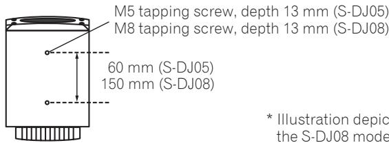
-
These speakers are provided with no accessory speaker stands, mounting fixtures, or screws. If such facilities are desired, please provide your own as required.
-
As shown in the accompanying illustration, two screw holes are provided on the bottom of each speaker to allow attachment to speaker mounting fixtures. When using such a mounting fixture, consult the usage instructions provided with the fixture and be sure it is capable of supporting the weight of the speaker. An improperly supported speaker could fall, causing serious damage or personal injury.
- Pioneer accepts no responsibility for any damages or other issues arising from the use of speaker mounting fixtures, including mistaken or insufficient assembly, improper installation, insufficient ability to support speaker weight, misuse, modification, or accidents.
Note:
- Over tightening of screws could cause stripping of threads and damage to the product. Take proper precautions when tightening.
Attaching the rubber feet
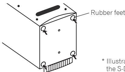
- Illustration depicts the S-DJ08 model.
The provided rubber feet may be used in accordance with the needs of the installation. Attach one rubber foot to each corner of the bottom of the speaker. Note that insufficient slip-resistance may be provided by the rubber feet in some locations, so they should not be used on slippery surfaces.
Note:
- Never attempt to attach the rubber feet while holding the speaker in a tilted attitude. Place a soft cloth or blanket on the floor, and lay the speaker on its side when attaching the feet.
Names and Functions of Parts
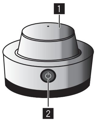
Front Panel Facilities
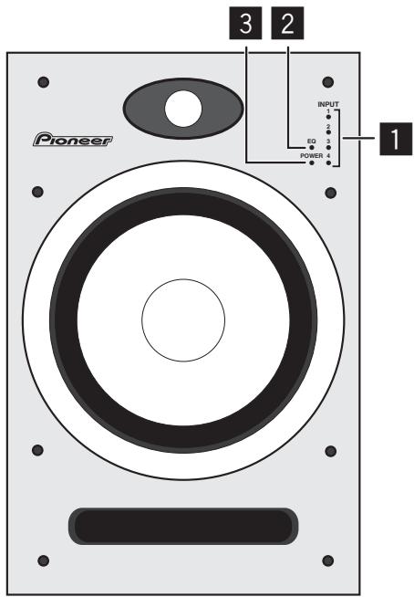
INPUT 1-4 indicators
Indicator lights for selected INPUT. During MUTE, the selected INPUT indicator flashes.
2 EQ indicator
Lights when equalizer function is ON.
3 POWER indicator/clipping indicator
Standby : Lights red.
Power ON Lights blue.
Power OFF : Indicator light is OFF.
During clipping : flashes or lights steadily pink.
If the amplifier generates signal clipping, this indicator flashes (or lights steadily) pink. In normal use, the speakers should be used so that the indicator does not flash or light steadily pink. In the event this indicator flashes (or lights steadily) pink, either lower the sound volume (LEVEL dial) on the unit's rear panel, or else lower the level of the signal input to this unit from the connected source component. Allowing excessive signal clipping may damage this unit.
CAUTION
This product has been designed so that all indicator lights will turn off when the user switches the appropriate controls on the speaker body, or switches on the controller (when a controller is provided as accessory). This condition makes it appear the same as though the speaker has been disconnected (unplugged) from its power source, but even at such times, electrical power is still being supplied to the unit. In order to completely turn off all electrical power to the unit, it is necessary to physically disconnect the unit's power plug from its power outlet. As a fire-prevention measure, the product should be installed within easy reach of its power outlet so that the power plug can be disconnected whenever you go on a trip or are otherwise not using the unit for an extended period of time.
Rear Panel Facilities
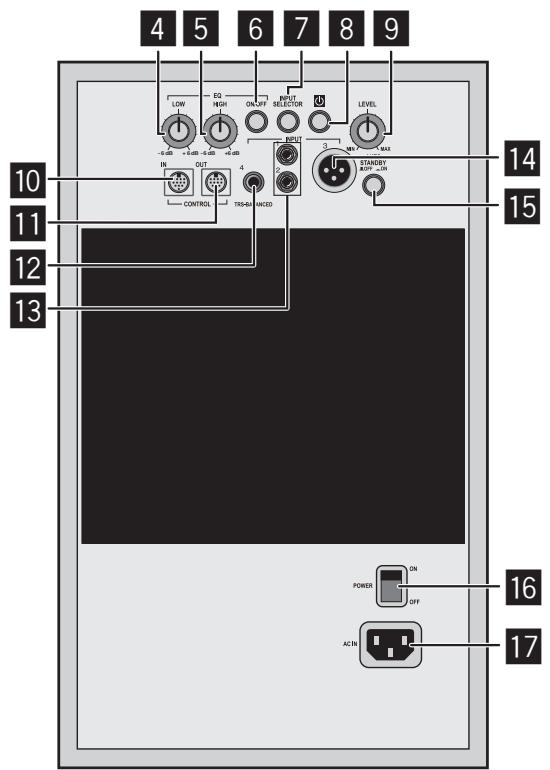
* Illustration depicts the S-DJ08 model.
4 EQ LOW dial
Use to adjust low-frequency sounds. This dial functions only when the EQ ON/OFF button is set to ON.
5 EQ HIGH dial
Use to adjust high-frequency sounds. This dial functions only when the EQ ON/OFF button is set to ON.
6 EQ ON/OFF button
Use to turn equalizer ON and OFF.
7 INPUT SELECTOR button
Each time button is pressed, the input alternates in the order INPUT 1 2 3 4
8 Power ON/Standby button ()
Use to switch unit between power ON and Standby modes. When the button is pressed, power is turned on; when the button is pressed again, the unit enters the standby mode.
LEVEL dial
Use to adjust the sound level (volume). This dial operates when no controller is connected.
10 CONTROL IN connector
Use to connect the accessory controller or accessory Link cable.
11 CONTROL OUT connector
Use to connect the accessory Link cable.
12 INPUT 4
Balanced-input phone jack.
Note:
- Unbalanced-type cables with phone plugs can also be used, but the volume of sound will be reduced. When you desire higher volumes of sound, use a balanced cable equipped with a TRS phone plug.
13 INPUT 1, INPUT 2
RCA pin-type unbalanced input jacks.
14 INPUT 3
XLR type balanced input connector. The connector's pin array is as follows: No. 1 Ground, No. 2 Hot, and No. 3 Cold.
15 AUTO STANDBY ON/OFF switch
Use to turn the power save function ON/OFF.
16 Main POWER switch
Use to turn main power ON and OFF.
17 ACIN
Connect the accessory power cord here and to an AC power outlet. Do not plug in the power cord until all other connections have been completed. Use only the furnished accessory power cord.
Controller front surface
LEVEL dial
Use to control sound level (volume).
2 Power ON/Standby button ()
Use to switch unit's power between ON and Standby modes. When the button is pressed, power is turned on; when the button is pressed again, the unit enters the Standby mode.
Controller rear surface
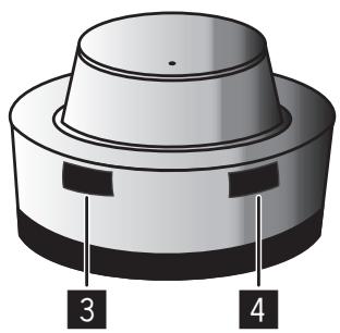
3 INPUT SELECTOR button
Each time the button is pressed, the input selector alternates in the order INPUT 1 2 3 4 .
4 MUTE/EQ button
Each time the button is pressed, the mute function switches ON/OFF. Hold the button depressed for one second or more to switch the equalizer function ON/OFF.
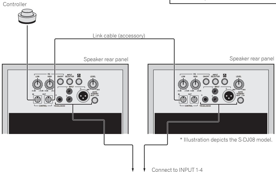
Connections
When making or changing connections, always turn off the power and disconnect the power cord from its outlet.
Also, be sure to read the operating instructions for the other components to which you are connecting these speakers.
Do not connect the power cord until all other connections are completed.
Use only the furnished accessory power cord.
In the event that the desired installation requires a longer Link cable than the one provided, purchase a commercially available MINI DIN 8a extension cable and connect it to the furnished Link cable.

Do not use a commercially available MINI DIN 8a extension cable alone; always connect it to the Link cable furnished as an accessory with this unit, since malfunctions, fire, or electric shock could result if the furnished cable is not used.
Note:
- When controller and Link cable are connected, set the speaker's main LEVEL dial fully counterclockwise to the MIN position, since an unexpected loud sound could be emitted from the speaker in the event the controller and Link cable are suddenly detached.
- When connecting the controller, set the controller's LEVEL dial fully counterclockwise to the MIN position, then adjust the sound level as desired after the connection is complete. If the connection is performed when the controller's LEVEL dial is at a high setting, an unexpected loud sound could be emitted from the speaker.
When the controller is connected, the speaker's main LEVEL dial function is disabled.
If the controller is connected to one speaker's CONTROL IN connector, use the Link cable to connect that speaker's CONTROL OUT connector to the other speaker's CONTROL IN connector.
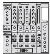
DJ mixer

TV
Portable audio
Operation
Turn on main power.
Set the main POWER switch on speaker rear panel to ON.
Set power ON/Standby.
Press the power ON/Standby button (on the controller or speaker rear panel).
Select the desired input.
Press the INPUT SELECTOR button (on the controller or speaker rear panel) to select the desired input source.
Adjust the sound volume.
If controller is connected: Slowly rotate the controller's LEVEL dial to adjust the sound volume as desired.
If controller is not connected: Slowly rotate the LEVEL dial on the speaker's rear panel to adjust the sound volume as desired.
Note:
- When two or more audio sources are connected: When changing the INPUT SELECTOR setting, the sound volume produced by the speakers may change greatly due to differences in output settings on the different audio sources. To avoid this, rotate the LEVEL dial fully counterclockwise (MIN) before changing the INPUT SELECTOR setting, the readjust the sound level as desired.
- Sound from speakers may be distorted, depending on the output level of the connected audio device. In this case, lower the output level of the device.
- If the equalizer control is adjusted toward the "+" side while the sound volume is raised, distortion may occur. In this event, lower the sound volume, or adjust the equalizer to a level that does not cause distortion.
- This unit is equipped with a self-resetting protection circuit. In the event of an potentially damaging signal input, the protection circuit may operate to prevent sound from being generated from the woofer or the tweeter; if this happens, either lower the sound volume (LEVEL dial) on the unit's rear panel, or lower the level of the signal input to this unit from the connected source component, and wait for a few minutes. The protection circuit will self-reset, and sound will be restored. If the sound does not return to its original volume, the unit may be damaged; in this event, consult one of the service stations, or consult your dealer.
Using the MUTE function
Press the controller's MUTE/EQ button to set the MUTE function to ON.
Setting the Equalizer
On the rear panel of the speaker, set the EQ ON/OFF button to ON, then use the EQ LOW and EQ HIGH dials to adjust the tone quality as desired.
Using the Equalizer
To set the equalizer to ON, press the controller's MUTE/EQ button and hold depressed for one second or more, or else press the EQ ON/OFF button on the rear panel of the speaker.
Power Save Function
Set the AUTO STANDBY ON/OFF switch (on speaker rear panel) to ON.
When the following conditions are met for 60 minutes, the unit will automatically switch to standby mode:
The LEVEL dial, control buttons, and other dials and controls are not operated.
The speaker receives no input signal of -40dB or greater.
Additional Information
Troubleshooting
If you think you are experiencing a malfunction with this unit, check the following items. Also check other devices connected to the unit. If the problem persists, consult your dealer for service.
- On occasion, the unit may fail to operate properly due to static electricity or other external conditions. In this event, disconnect the power cord and wait for five minutes or more, then reconnect the power cord and check for proper operation.
| Symptom | Items to Check | Remedy |
| No power | Is power cord connected properly? | Connect power cord to outlet (page 6). |
| No sound from connected audio devices, or sound is very small. | Has connected audio device been set properly? | Set device's output selector and sound volume properly. |
| Is connection cable connected properly? | Connect cables properly (page 8). | |
| Are connectors or plugs dirty? | Clean connectors and plugs before connecting. | |
| Is sound level set properly? | Slowly rotate LEVEL dial (on controller if connected, otherwise or speaker rear panel) clockwise. | |
| Does the selected input match the type of input connector for the connected device? | Select the input connector matching the desired device's type of input. | |
| Is the MUTE function set to ON? | Press the controller's MUTE/EQ button. | |
| Is the power turned ON? | Press the main POWER switch and power ON/Standby button. | |
| Sound is distorted. | Is sound volume set to proper level? | Slowly rotate LEVEL dial (on controller if connected, otherwise or speaker rear panel) counterclockwise to reduce the sound volume. |
| Is the output level of the connected audio device set properly? | Adjust the output level of the connected audio device properly. | |
| Feedback (continuous howling sound) | Is sound volume set properly? | Slowly rotate LEVEL dial (on controller if connected, otherwise or speaker rear panel) counterclockwise to reduce the sound volume. |
| Controller doesn't respond. | Is controller cable connected properly? | Connect controller cable properly. |
| Right/Left speakers don't produce same sound volume when using controller. | Is controller cable connected properly? | Connect controller cable properly. |
| Is Link cable connected properly? | Connect Link cable properly. | |
| Input selector doesn't operate. | Is controller cable connected properly? | Connect controller cable properly. |
| Is Link cable connected properly? | Connect Link cable properly. | |
| MUTE function doesn't operate. | Is controller cable connected properly? | Connect controller cable properly. |
| Is Link cable connected properly? | Connect Link cable properly. | |
| Can't set EQ ON/OFF. | Is controller cable connected properly? | Connect controller cable properly. |
| Is Link cable connected properly? | Connect Link cable properly. | |
| Equalizer (EQ) function doesn't operate. | Is EQ set to ON? | Press the EQ ON/OFF button on the speaker's rear panel. Alternately, hold the controller's MUTE/EQ button depressed one second or more. |
Specifications
S-DJ08
Type....... Magnetically shielded bi-amp 2-way active speaker
Amplifier
Dynamic power (HF/LF). 70 W/170 W
Input connectors (balanced input)
XLR x 1, TRS (1/4 inch Phone) x 1
Input connectors (unbalanced input). RCA x 2
Input sensitivity/impedance
6 dBu/10 kΩ (XLR, TRS (1/4 inch Phone)) -3 dBu/10 kΩ (RCA)
Speaker
Enclosure. Bass reflex
Woofer 20 cm PP cone
Tweeter 2.5 cm soft dome
Playback response 43 Hz to 26 kHz (-10 dB)
Power unit/other
Crossover frequency. 5.8 kHz
Power consumption. 100 W
External dimensions.... 250 mm (W) x 391 mm (H) x 328 mm (D)
(not including heat sink) 371 mm (D)
(including heat sink)
Weight (each) 13.5 kg
Functions
Input selector, mute mode, clipping indicator, EQ Low -6 dB to +6 dB, EQ High -6 dB to +6 dB, EQ ON/OFF button
S-DJ05
Type....... Magnetically shielded bi-amp 2-way active speaker
Amplifier
Dynamic power (HF/LF) 30 W/50 W
Input connectors (balanced input)
XLR x 1, TRS (1/4 inch Phone) x 1
Input connectors (unbalanced input) RCA x 2
Input sensitivity/impedance
6 dBu/10 kΩ (XLR, TRS (1/4 inch Phone)) -3 dBu/10 kΩ (RCA)
Speaker
Enclosure. Bass reflex
Woofer 13 cm PP cone
Tweeter 2.5 cm soft dome
Playback response .50 Hz to 25 kHz (-10 dB)
Power unit/other
Crossover frequency. 3.0 kHz
Power consumption. .45 W
External dimensions.... 185 mm (W) x 301 mm (H) x 220 mm (D) (not including heat sink) 258 mm (D) (including heat sink)
Weight (each) 6.7 kg
Functions
Input selector, mute mode, clipping indicator, EQ Low -6 dB to +6 dB, EQ High -6 dB to +6 dB, EQ ON/OFF button
Common Specifications
Power.. AC 230 V, 50 Hz/60 Hz Power consumption during standby mode. .0.5 W or less
Accessories
Power cords. 2
Link cable. 1
Controller. 1
Rubber feet.. 8
Warranty
Operating Instructions (this document)
Specifications and design subject to possible modification without notice, due to improvements.
Published by Pioneer Corporation. Copyright © 2010 Pioneer Corporation. All rights reserved.
IMPORTANT

Publication de Pioneer Corporation. © 2010 Pioneer Corporation.
WAARSCHUWING NETSNOER
1 INPUT 1-4 indicators
16 Interruptor POWER principal
Published by Pioneer Corporation.
Copyright © 2010 Pioneer Corporation.
All rights reserved.
Publication de Pioneer Corporation.
© 2010 Pioneer Corporation.
PIONEER ELECTRONICS (USA) INC.
P.O. BOX 1540, Long Beach, California 90801-1540, U.S.A. TEL: (800) 421-1404
PIONEER ELECTRONICS OF CANADA, INC.
300 Allstate Parkway, Markham, Ontario L3R 0P2, Canada TEL: 1-877-283-5901, 905-479-4411
PIONEER EUROPE NV
Haven 1087, Keetberglaan 1, B-9120 Melsele, Belgium TEL: 03/570.05.11
PIONEER ELECTRONICS ASIACENTRE PTE. LTD.
253 Alexandra Road, #04-01, Singapore 159936 TEL: 65-6472-7555
PIONEER ELECTRONICS AUSTRALIA PTY. LTD.
5 Arco Lane, Heatherton, Victoria, 3202, Australia, TEL: (03) 9586-6300
PIONEER ELECTRONICS DE MEXICO S.A. DE C.V.
Blvd.Manuel Avila Camacho 138 10 piso Col.Lomas de Chapultepec, Mexico, D.F. 11000 TEL: 55-9178-4270
K002_B2_En