USER MANUAL DJM-800 PIONEER
Operating Instructions
Mode d'emploi
Bedienungsanleitung
Thank you for buying this Pioneer product.
Please read through these operating instructions so you will know how to operate your model properly. After you have finished reading the instructions, put them away in a safe place for future reference.
In some countries or regions, the shape of the power plug and power outlet may sometimes differ from that shown in the explanatory drawings. However the method of connecting and operating the unit is the same.
IMPORTANT

The lightning flash with arrowhead symbol, within an equilateral triangle, is intended to alert the user to the presence of uninsulated "dangerous voltage" within the product's enclosure that may be of sufficient magnitude to constitute a risk of electric shock to persons.
CAUTION
RISK OF ELECTRIC SHOCK DO NOT OPEN

CAUTION:
TO PREVENT THE RISK OF ELECTRIC SHOCK,DO NOT REMOVE COVER (OR BACK).NO USER-SERVICEABLE PARTS INSIDE.REFER SERVICING TO QUALIFIED SERVICE PERSONNEL.
The exclamation point within an equilateral triangle is intended to alert the user to the presence of important operating and maintenance (servicing) instructions in the literature accompanying the appliance.
D3-4-2-1-1 En-A
Replacement and mounting of an AC plug on the power supply cord of this unit should be performed only by qualified service personnel.
IMPORTANT: THE MOULDED PLUG
This appliance is supplied with a moulded three pin mains plug for your safety and convenience. A 3 amp fuse is fitted in this plug. Should the fuse need to be replaced, please ensure that the replacement fuse has a rating of 3 amps and that it is approved by ASTA or BSI to BS1362.
Check for the ASTA mark or the BSI mark on the body of the fuse.
If the plug contains a removable fuse cover, you must ensure that it is refitted when the fuse is replaced. If you lose the fuse cover the plug must not be used until a replacement cover is obtained. A replacement fuse cover can be obtained from your local dealer.
If the fitted moulded plug is unsuitable for your socket outlet, then the fuse shall be removed and the plug cut off and disposed of safely. There is a danger of severe electrical shock if the cut off plug is inserted into any 13 amp socket.
If a new plug is to be fitted, please observe the wiring code as shown below. If in any doubt, please consult a qualified electrician.
IMPORTANT: The wires in this mains lead are coloured in accordance with the following code:
Blue: Neutral Brown:Live
As the colours of the wires in the mains lead of this appliance may not correspond with the coloured markings identifying the terminals in your plug, proceed as follows ;
The wire which is coloured BLUE must be connected to the terminal which is marked with the
letter N or coloured BLACK
The wire which is coloured BROWN must be connected to the terminal which is marked with the
letter L or coloured RED
How to replace the fuse: Open the fuse compartment with a screwdriver and replace the fuse.
D3-4-2-1-2-B_En
Operating Environment
Operating environment temperature and humidity: +5^ + + 35^(+41^ + + 95^) less than 85% R (cooling vents not blocked)
Do not install this unit in a poorly ventilated area, or in locations exposed to high humidity or direct sunlight (or strong artificial light) D3-4-2-1c_A_En
WARNING
To prevent a fire hazard, do not place any naked flame sources (such as a lighted candle) on the equipment. D3-4-2-1-7a
WARNING
Before plugging in for the first time, read the following section carefully.
The voltage of the available power supply differs according to country or region. Be sure that the power supply voltage of the area where this unit will be used meets the required voltage (e.g., 230V or 120V) written on the rear panel. D3-4-2-1-4_A_En

If you want to dispose this product, do not mix it with general household waste. There is a separate collection system for used electronic products in accordance with legislation that requires proper treatment, recovery and recycling.
Private households in the 25 member states of the EU, in Switzerland and Norway may return their used electronic products free of charge to designated collection facilities or to a retailer (if you purchase a similar new one). For countries not mentioned above, please contact your local authorities for the correct method of disposal. By doing so you will ensure that your disposed product undergoes the necessary treatment, recovery and recycling and thus prevent potential negative effects on the environment and human health.
If the AC plug of this unit does not match the AC outlet you want to use, the plug must be removed and appropriate one fitted. Replacement and mounting of an AC plug on the power supply cord of this unit should be performed only by qualified service personnel. If connected to an AC outlet, the cut-off plug can cause severe electrical shock. Make sure it is properly disposed of after removal. The equipment should be disconnected by removing the mains plug from the wall socket when left unused for a long period of time (for example, when on vacation). D3-4-2-2-1a_A_En
CAUTION
The POWER switch on this unit will not completely shut off all power from the AC outlet. Since the power cord serves as the main disconnect device for the unit, you will need to unplug it from the AC outlet to shut down all power. Therefore, make sure the unit has been installed so that the power cord can be easily unplugged from the AC outlet in case of an accident. To avoid fire hazard, the power cord should also be unplugged from the AC outlet when left unused for a long period of time (for example, when on vacation). D3-4-2-2-2a_A_En
WARNING
This equipment is not waterproof. To prevent a fire or shock hazard, do not place any container filed with liquid near this equipment (such as a vase or flower pot) or expose it to dripping, splashing, rain or moisture. D3-4-2-1-3.A.Er
VENTILATION CAUTION
When installing this unit, make sure to leave space around the unit for ventilation to improve heat radiation (at least 5 cm at rear, and 3 cm at each side).
WARNING
Slots and openings in the cabinet are provided for ventilation to ensure reliable operation of the product, and to protect it from overheating. To prevent fire hazard, the openings should never be blocked or covered with items (such as newspapers, table-cloths, curtains) or by operating the equipment on thick carpet or a bed. D3-4-2-1-7b_A_En
This product complies with the Low Voltage Directive (73/23/EEC, amended by 93/68/EEC), EMC Directives (89/336/EEC, amended by 92/31/EEC and 93/68/EEC). D3-4-2-1-9a_En
POWER-CORD CAUTION
Handle the power cord by the plug. Do not pull out the plug by tugging the cord and never touch the power cord when your hands are wet as this could cause a short circuit or electric shock. Do not place the unit, a piece of furniture, etc., on the power cord, or pinch the cord. Never make a knot in the cord or tie it with other cords. The power cords should be routed such that they are not likely to be stepped on. A damaged power cord can cause a fire or give you an electrical shock. Check the power cord once in a while. When you find it damaged, ask your nearest PIONEER authorized service center or your dealer for a replacement. S002_En
CAUTIONS REGARDING HANDLING
Location
Install the unit in a well-ventilated location where it will not be exposed to high temperatures or humidity.
- Do not install the unit in a location which is exposed to direct rays of the sun, or near stoves or radiators. Excessive heat can adversely affect the cabinet and internal components. Installation of the unit in a damp or dusty environment may also result in a malfunction or accident. (Avoid installation near cookers etc., where the unit may be exposed to oily smoke, steam or heat.)
- When the unit is used inside a carrying case or DJ booth, separate it from the walls or other equipment to improve heat radiation.
Cleaning the Unit
- Use a polishing cloth to wipe off dust and dirt.
- When the surfaces are very dirty, wipe with a soft cloth dipped in some neutral cleanser diluted five or six times with water and wrung out well, then wipe again with a dry cloth. Do not use furniture wax or cleaners.
- Never use thinners, benzene, insecticide sprays or other chemicals on or near this unit, since these will corrode the surfaces.
CONTENTS
CAUTIONS REGARDING HANDLING 2
CONFIRM ACCESSORIES 3
FEATURES 3
BEFORE USING
CONNECTIONS 4
CONNECTION PANEL 4
CONNECTING INPUTS 5
CONNECTING EXTERNAL EFFECTORS,
OUTPUT CONNECTORS 6
ABOUT MIDI CONNECTORS 6
CONNECTING MICROPHONE AND
HEADPHONES 7
CONNECTING THE POWER CORD 7
NAMES AND FUNCTIONS OF PARTS 8
OPERATION PANEL 8
DISPLAY SECTION 10
OPERATIONS
MIXER OPERATIONS 12
BASIC OPERATIONS 12
FADER START FUNCTION 13
EFFECT FUNCTIONS 14
TYPES OF BEAT EFFECTS 14
PRODUCING BEAT EFFECTS 16
TYPE OF SOUND-COLOR EFFECT 17
USING SOUND-COLOR EFFECTS 17
EFFECT PARAMETERS 18
MIDI SETTINGS 19
SYNCHRONIZING AUDIO SIGNALS TO
EXTERNAL SEQUENCER, OR USING
DJM-800 INFORMATION TO OPERATE
AN EXTERNAL SEQUENCER 19
MIDI MESSAGES 19
PROGRAM CHANGE 20
SNAPSHOT 20
OTHER
TROUBLESHOOTING 21
SPECIFICATIONS 22
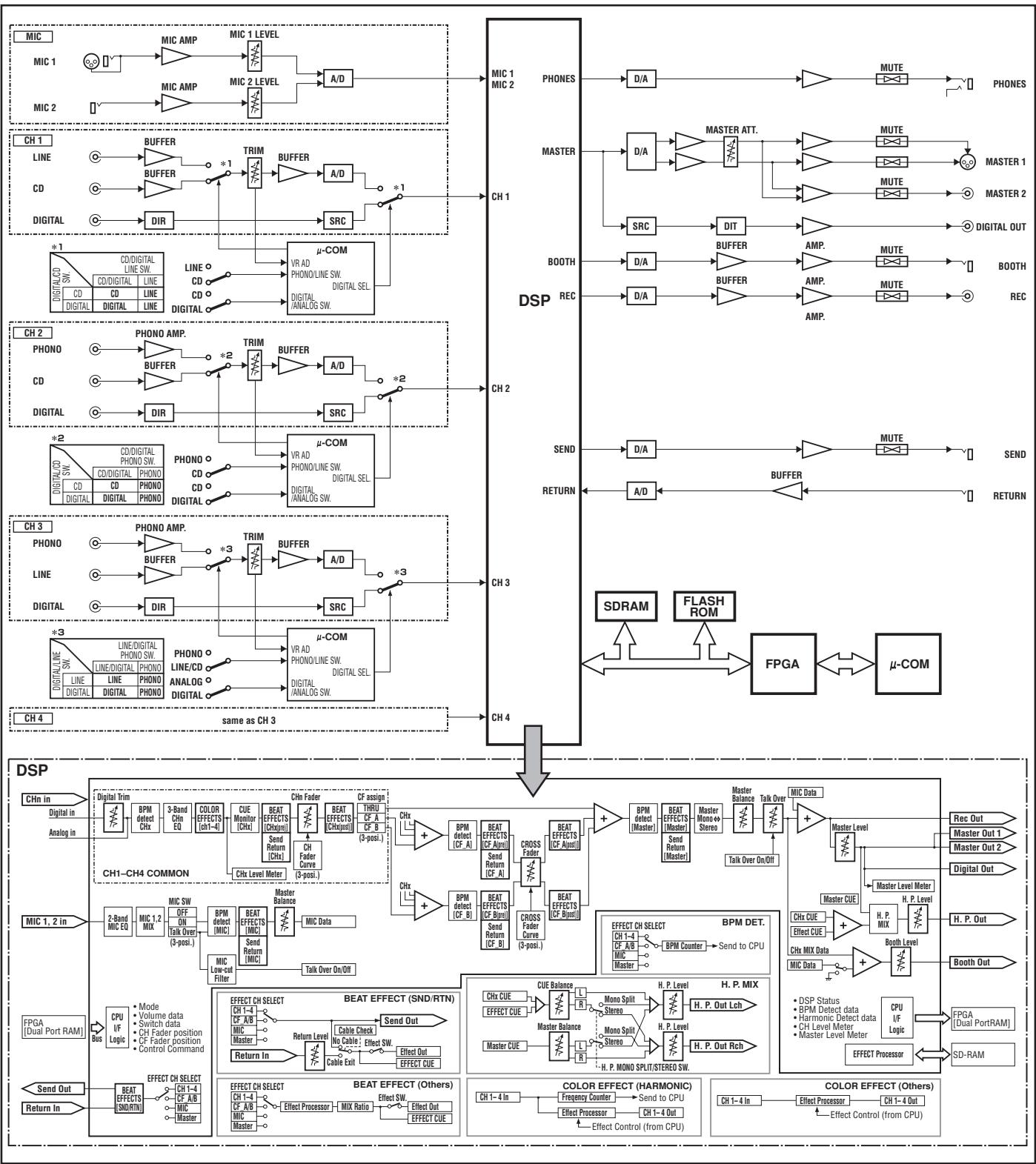
BLOCKDIAGRAM 128
CONFIRM ACCESSORIES
Operating Instructions. 1
Power cord 1
FEATURES
① Designed for high sound quality
Analog signals are transmitted by the shortest circuitry and converted to digital format at 96kHz sampling rate via a 24-bit high quality A/D converter. As a result, signals are passed to the digital mixing stage in the best possible state. Mixing is performed with a 32-bit DSP, totally eliminating any loss in fidelity, while the ideal level of filtering is introduced to produce optimum sound for DJ play.
These features are housed in a high-rigidity chassis with double-shielded construction together with a high-performance power section and other features of the high-fidelity technology also used in the DJM-1000, thus guaranteeing the utmost in clear and powerful club sounds.
② Sound-color effects
1) Harmonic effect
Equipped with the industry's first "harmonic effect" function that detects the track's key and provides optimum tuning for DJ play.
This new function allows smoother, more natural DJ mixing compared to earlier models which allowed DJ play with track tempo adjustment alone.
2) Modulation effect
"Filter," "crush," and "sweep" effects have been added to each channel.
These allow a greater breadth to DJ play by permitting the user to apply effects more intuitively.
Also, by combining these with "beat effects," some 50 kinds of effect can be produced, giving the user a vast potential for remix and DJ play.
③ Beat effects
The "beat effects" so popular on the DJM-600 are continued here. Effects can be applied in linkage to the BPM (Beats Per Minute) count, thus allowing the production of a variety of sounds.
Some of the effects include delay, echo, reverse delay, pan, trance, filter, flanger, phaser, reverb, robot, chorus, roll, and reverse roll.
④ Digital IN/OUT
The digital input connectors support each of the sampling rates (44.1/ 48/96 kHz), thus allowing the connection of digital components for a DJ system with no sound degradation.
Likewise the digital output connectors support sampling rates 96 kHz/24-bit and 48 kHz/24-bit, making the unit even more convenient for cutting studio tracks or on other occasions when high sound fidelity is required. (Only linear PCM is supported.)
⑤ MIDI OUT
Virtually all the dial and switch information of the DJM-800 can be output in MIDI signal format, allowing external components to be controlled via MIDI.
Other functions
- A control cable can be used to connect the unit to a Pioneer DJ CD player, thus allowing playback to be linked to operation of the fader ("fader start play").
- Built-in "3-band equalizer" supports level control within the range of +6 dB to -26 dB in each bandwidth.
- "Cross fader assignment" function allows each channel's input to be assigned flexibly to a cross fader.
- "Talk over" function automatically lowers track volume during microphone input.
- "Fader curve adjustment" function allows modification of the cross fader and channel fader curves.
- "Microphone cut" function mutes microphone output to the booth monitor, thus preventing uncomfortable feedback.
- By replacing the channel fader section with the optional rotary volume kit DJC-800RV, the slider control can be replayed with a rotary type control.
CONNECTIONS
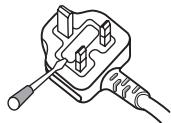
CONNECTION PANEL
1. POWER switch
2. MASTER 2 output connectors
RCA type unbalanced output.
3. Recording output connectors (REC)
RCA type output connectors for recording.
RCA type phono level (MM cartridge) input connectors.
Do not use for inputting line level signals.
RCA type line level input connectors.
Use to connect a cassette deck or other line level output component.
6. Signal grounding terminals (SIGNAL GND)
Use to connect ground wires from analog players.
This is not a safety grounding terminal.
RCA type line level input connectors.
Use to connect a DJ CD player or other line level output component.
8. DIGITAL IN connectors
RCA type digital coaxial input connectors.
Use to connect to DJ CD player or other digital coaxial output connectors.
9. MIDI OUT connector
DIN type output connector.
Use to connect to other MIDI component (see P. 19).
10. DIGITAL OUT connector
RCA type digital coaxial output connector.
Master audio digital output.
11. Sampling frequency selector switch (fs 48 k/96 k)
Use to set the sampling frequency of the digital output to 96 kHz/24-bit or 48 kHz/24-bit.
Use to select either analog input (CD) or digital input (DIGITAL IN).
13. RETURN connectors
6.3 ~mm phone-type input connectors.
Use to connect to the output connectors of external effectors or similar components.
When the L channel only is connected, the L channel input is simultaneously input to the R channel.
14. SEND output connectors
6.3 mm phone-type output connectors.
Use to connect to the input connectors of external effectors or other similar components. When the L channel only is connected, a L + R monaural signal is output.
15. CONTROL connectors
Ø3.5 mm mini-connector. Use to connect to the control connector of a Pioneer DJ CD player.
When the connectors are connected, the DJM-800's fader can be used to perform start/stop on the DJ CD player.
16. BOOTH monitor output connectors
06.3 mm phone-type booth monitor output connectors.
The sound level from these connectors is controlled independently by the BOOTH MONITOR level dial, regardless of the position of the MASTER LEVEL dial. (These connectors are TRS output, so they support both balanced and unbalanced outputs.)
Use to select either analog input (LINE) or digital input (DIGITAL IN).
18. Master output attenuator switch (MASTER ATT)
Use to attenuate the level of the master 1 and master 2 outputs. Selectable values are 0dB, -3dB, -6dB and -12dB .
19. Microphone signal switch (MIC SIGNAL ADD/CUT)
When set to the [ADD] position, the sounds from microphone 1 and microphone 2 are output to the BOOTH monitor output connectors. When set to the [CUT] position, the sounds from microphone 1 and microphone 2 are not output to the BOOTH monitor output connectors.
20. MASTER 1 output connectors
XLR type (male) balanced output.
- When using a cord with RCA-type plug, users are recommended to connect the plug directly to the MASTER 2 connectors without using an XLR/RCA converter plug.
21. Power inlet (AC IN)
Use the accessory power cord to connect to an AC power outlet of the proper voltage.
Always turn off the power switch and disconnect the power plug from its outlet when making or changing connections.
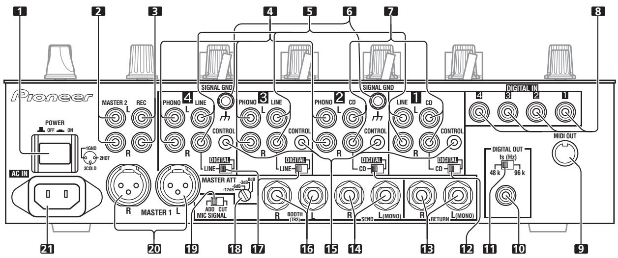
Pioneer DJ CD players
Connect a DJ CD player's audio output connectors to one of the channel 1 to 2 CD input connectors or the channel 3 to 4 LINE input connectors, and connect the player's control cable to the corresponding channel's CONTROL connector.
Set the connected channel's DIGITAL/CD switch or DIGITAL/LINE switch to either [CD] or [LINE], and set the input selector switch to [CD/DIGITAL] or [LINE/DIGITAL].
When making digital connections, connect the digital coaxial output terminal of the DJ CD player to one of the channel 1 to 4 DIGITAL IN connectors of the DJM-800; then set the corresponding channel's DIGITAL/CD switch or DIGITAL/LINE switch to [DIGITAL], and the input selector switch to [CD/DIGITAL] or [LINE/DIGITAL].
Analog turntable
To connect an analog turntable, connect the turntable's audio output cable to one of the channel 2 to 4 PHONO input connectors. Set the corresponding channel's input selector switch to [PHONO]. The DJM-800's PHONO inputs support MM cartridges.
Connect the turntable's ground wire to one of the DJM-800's SIGNAL GND terminals.
Note that no PHONO input connector is provided for channel 1.
Connecting other line level output devices
To use a cassette deck or other CD player, connect the component's audio output connectors to one of the channel 3 to 4 LINE input connectors. Then set the corresponding channel's DIGITAL/LINE switch to [LINE], and the input selector switch to [LINE/DIGITAL]. Alternately, connect the component to the channel 1 LINE input connector, then set the channel 1 input selector switch to [LINE].
Connecting other digital output devices
To use a CD player or other component with digital connections, connect the component's digital coaxial output connectors to one of the channel 1 to 4 DIGITAL IN connectors; then set the corresponding channel's DIGITAL/CD switch or DIGITAL/LINE switch to [DIGITAL], and the input selector switch to [CD/DIGITAL] or [LINE/DIGITAL].
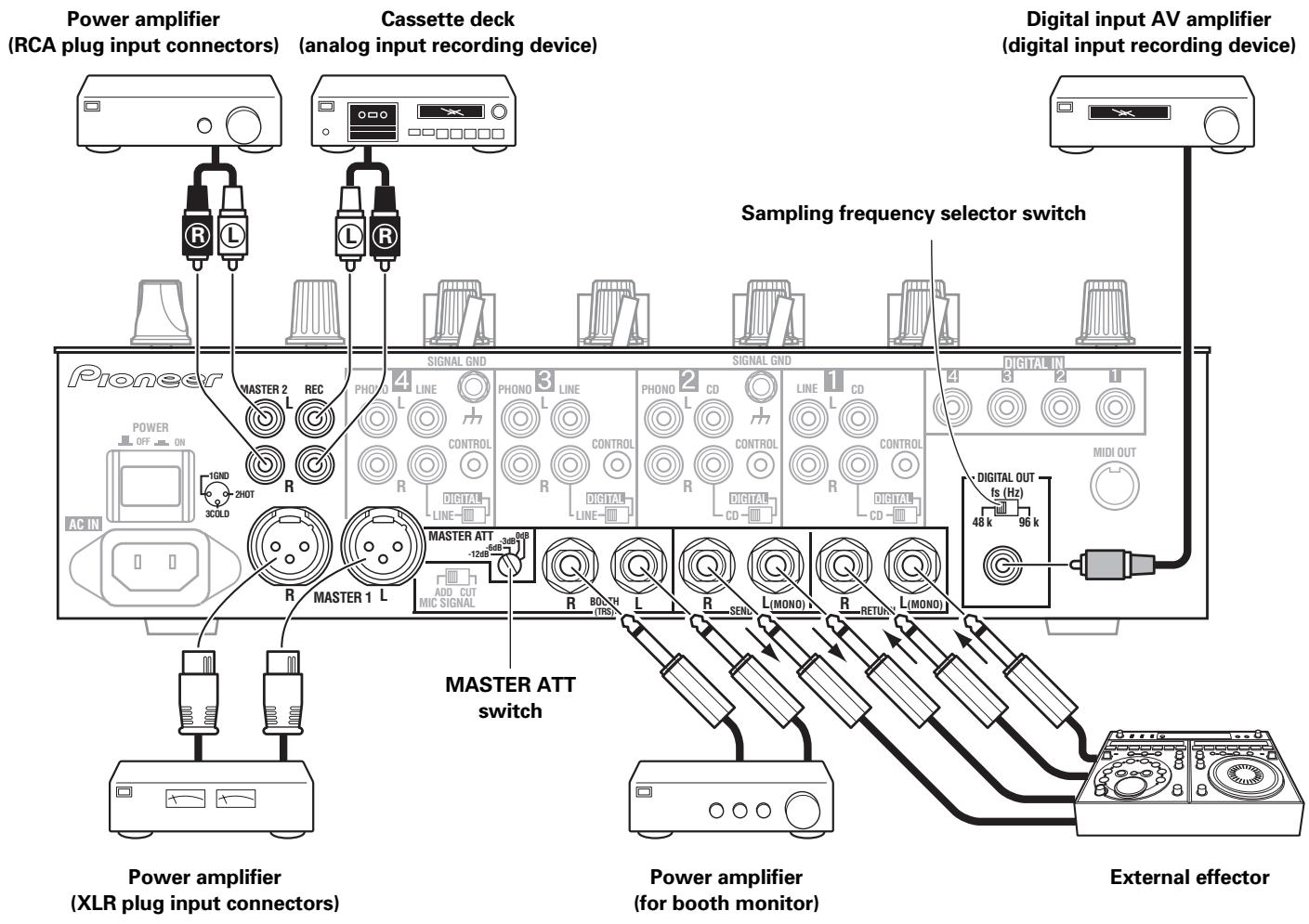
CONNECTING EXTERNAL EFFECTORS, OUTPUT CONNECTORS
Master output
This unit is furnished with balanced output MASTER 1 (supporting XLR plugs), and unbalanced output MASTER 2 (supporting RCA plugs).
Using the MASTER ATT switch, adjust the output level to match the input sensitivity of the power amplifier used.
If the operating panel's STEREO/MONO switch is set to [MONO], the master output will be a monaural combination of L+R channels.
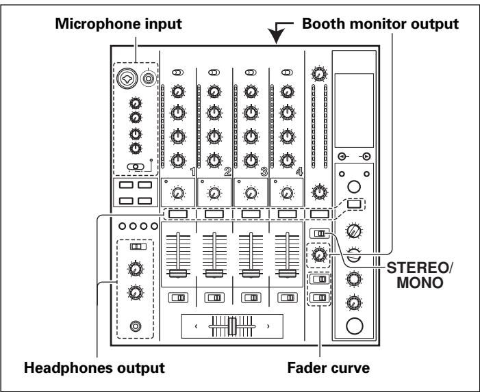
Booth monitor output
This is a TRS output supporting 06.3 mm phone plugs. The sound volume for this output is controlled by the BOOTH MONITOR level dial, independently of the master output level setting.
Recording output
These are output connectors for recording, supporting RCA plugs.
Digital output
This is a coaxial digital output connector, supporting RCA plugs. The sampling frequency can be set to 96 kHz/24-bit or 48 kHz/24-bit to match the connected device.
External effector
Use a cable with 6.3 mm phone plugs to connect the DJ mixer's SEND connectors to the effector's input connectors.
When using an effector with monaural inputs, connect only to the DJ mixer's L channel output. In this way, the mixed L+R audio signal will be sent to the effector. In the same way, use a cable with 6.3 mm phone plugs to connect the DJ mixer's RETURN connectors to the output connectors of the effector.
If the effector has only monaural output, connect to the DJ mixer's L channel input only. The signal from the effector will be input to both L and R channels.
When using an external effector, set the effect selector to [SND/RTN].
ABOUT MIDI CONNECTORS
See P. 19 regarding the functions of MIDI connectors.
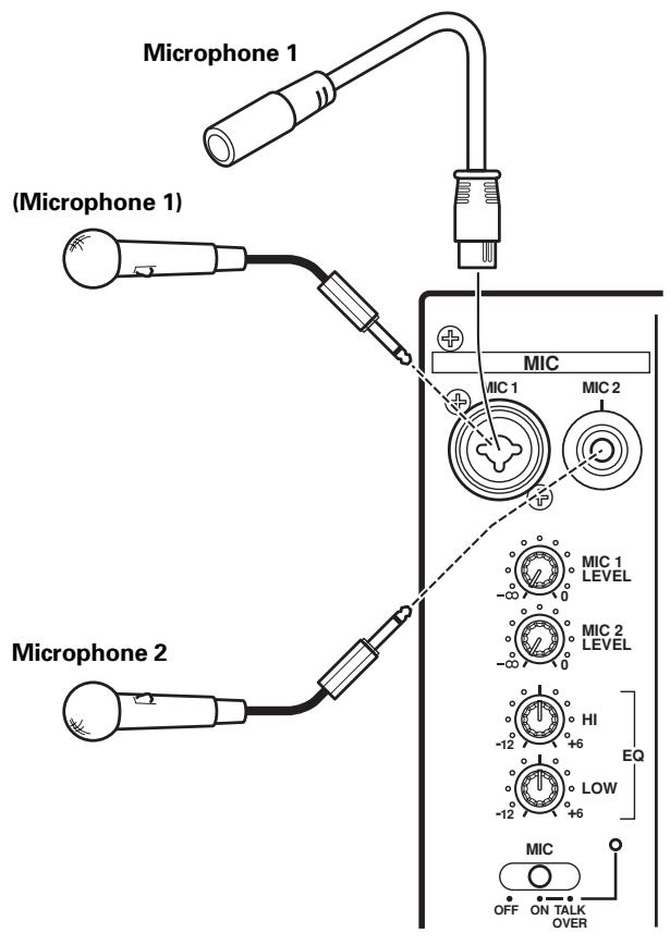
CONNECTING MICROPHONE AND HEADPHONES
Microphone
The MIC 1 jack on the upper surface of the operating panel can be used to connect a microphone with 6.3 mm phone plug or XLR plug.
The MIC 2 jack on the upper surface of the operating panel can be used to connect a microphone with 6.3 mm phone plugs.
- When the connection panel's MIC SIGNAL switch is set to [CUT], no microphone sounds will be output from the BOOTH monitor output connectors.
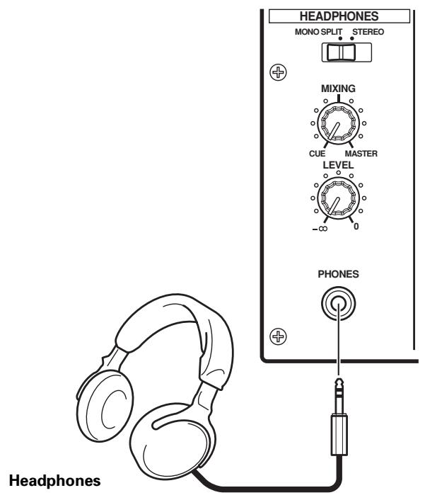
Headphones
The PHONES jack on the upper surface of the operating panel can be used to connect headphones with a 06.3 mm stereo phone plug.
Connect the power cord last.
After completing all other connections, connect the accessory power cord to the AC inlet on the back of the player, then connect the plug to a standard wall outlet or to the auxiliary power outlet of your amplifier.
- Use only the supplied power cord.
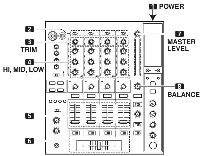
NAMES AND FUNCTIONS OF PARTS
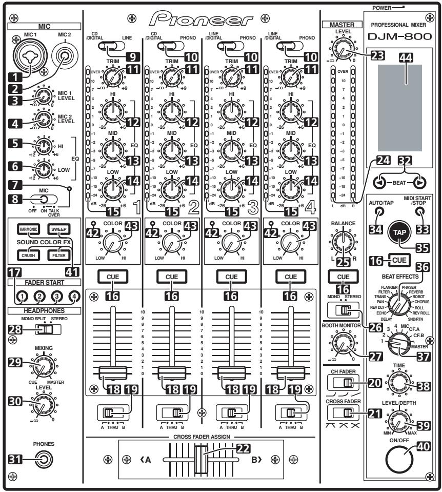
OPERATION PANEL
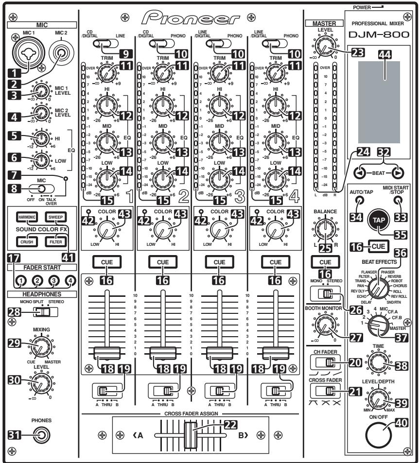
- Microphone 1 input jack (MIC 1)
Use to connect a microphone with an XLR or phone plug.
- Microphone 2 input jack (MIC 2)
Use to connect a microphone with a phone plug.
- Microphone 1 level control dial (MIC 1 LEVEL)
Use to adjust the volume of microphone 1. (adjustable range - to 0dB )
- Microphone 2 level control dial (MIC 2 LEVEL)
Use to adjust the volume of microphone 2. (adjustable range - to 0dB )
- Microphone equalizer high-range control dial (HI)
Use to adjust the treble (high-range) frequencies of microphones 1 and 2. (adjustable range -12 dB to +6 dB)
- Microphone equalizer low-range control dial (LOW)
Use to adjust the bass (low-range) frequencies of microphones 1 and 2. (adjustable range -12 dB to +6 dB)
- Microphone function indicator
Lights when microphone is ON; flashes when TALK OVER is ON.
8. Microphone function selector switch (MIC) OFF:
No microphone sound is output.
ON:
Microphone sound is output normally.
TALK OVER:
Microphone sound is output; when sound is input to a connected microphone, the TALK OVER function operates and all sound other than that from the microphone is attenuated by 20 dB.
CD/DIGITAL:
Use to select CD input connectors (line level analog input) or DIGITAL input connectors.
LINE:
Use to select LINE input connectors.
CD/DIGITAL (channel 2):
Use to select CD input connectors (line level analog input) or DIGITAL input connectors.
LINE/DIGITAL (channel 3 to 4):
Use to select LINE input connectors (line level analog input) or DIGITAL input connectors.
PHONO:
Use to select PHONO input connectors (analog turntable input).
11. TRIM adjust dial
Use to adjust the input level for each channel. (adjustable range: - to +9 dB, mid-position is about 0 dB)
12. Channel equalizer high-range adjust dial (HI)
Use to adjust the treble (high-range) frequency sound for each channel. (adjustable range: -26 dB to +6 dB)
13. Channel equalizer mid-range adjust dial (MID)
Use to adjust the mid-range frequency sound for each channel. (adjustable range: -26 dB to +6 dB)
14. Channel equalizer low-range adjust dial (LOW)
Use to adjust the bass (low-range) frequency sound for each channel. (adjustable range: -26 dB to +6 dB)
15. Channel level indicator
Displays the current level for each channel, with two-second peak hold.
These buttons are used to select from channel 1 to 4, MASTER, or effector, to allow you to monitor the desired source through headphones. If multiple buttons are pressed simultaneously, the selected audio sources are mixed. Press the button once more to cancel the selected source. Unselected buttons glow darkly, while selected source buttons light brightly.
Fader control section
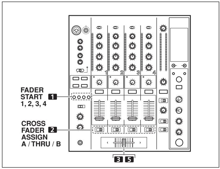
Enables the fader start/back cue function for the channel to which a DJ CD player is connected. The button lights when set to ON. When enabled, the operation differs depending on the setting of the CROSS FADER ASSIGN switch.
- When the CROSS FADER ASSIGN switch is set to the [A] or [B] position, fader start button operation is linked to the operation of the cross fader (and unlinked to channel fader).
- When the CROSS FADER ASSIGN switch is set to the [THRU] position, fader start button operation is linked to the operation of the channel fader (and unlinked to cross fader).
18. Channel fader lever
Use to adjust sound volumes for each channel. (adjustable range: - to 0 dB)
Output is in accordance with the channel fader curve selected with the CH FADER curve switch.
19. CROSS FADER ASSIGN switch
This switch assigns each channel's output to either right or left side of the cross fader (if multiple channels are assigned to the same side, the result will be the combined sum of the channels).
A:
The selected channel is assigned to the cross fader's A (left) side.
THRU:
The channel fader's output is sent as is to the master output, without being passed through the cross fader.
B:
The selected channel is assigned to the cross fader's B (right) side.
20. Channel fader curve switch (CH FADER)
This switch allows the user to select from three types of channel fader curve response. This setting is applied equally to channels 1 to 4.
- At the left setting, the curve operates to produce a rapid rise as the channel fader approaches its distant position.
- At the right setting, the curve operates to produce an even, neutral rise throughout the channel fader's movement.
- At the middle setting, an intermediate curve is produced, midway between the two curves noted above.
21. Cross fader curve switch (CROSS FADER)
This switch allows the user to select from three types of cross fader curve response.
- At the left setting, the curve produces a rapid signal rise. (As soon as the cross fader lever leaves the [A] side, the [B] channel sound is produced.)
- At the right setting, the curve operates to produce an even, neutral rise throughout the cross fader's movement.
- At the middle setting, an intermediate curve is produced, midway between the two curves noted above.
22. Cross fader lever
Outputs sound assigned to [A] and [B] sides in accordance with setting of the CROSS FADER ASSIGN switch, and subject to the cross fader curve selected with the CROSS FADER curve switch.
Master output control section
23. Master output level dial (MASTER LEVEL)
Use to adjust the master output level. (adjustable range: - to 0 dB)
The master output is the sum combination of the sound from channels set to [THRU] with the CROSS FADER ASSIGN switch; the signal passed through the cross fader; and the signals from microphone 1 and microphone 2 (if the effect selector is set to [SND/RTN], the RETURN input is also added).
24. Master level indicator (MASTER L, R)
These segment indicators display the output level from L and R channels. The indicators have a two-second peak hold.
25. Master balance dial (BALANCE)
Use to adjust the L/R channel balance for master output, booth monitor output, recording output, and digital output.
26. Master output STEREO/MONO selector switch
When set to [MONO], the master output becomes a monaural combination of L + R .
Booth monitor control section
27. BOOTH MONITOR level control dial
This dial is used to adjust the booth monitor output volume. The volume can be adjusted independently of the master output level. (adjustable range: - to 0 dB)
Headphones output section
28. Headphones output switch (MONO SPLIT/STEREO)
MONOSPLIT:
The audio source selected with the headphone CUE button is output to the L channel, and the master audio is output to the R channel (only when headphone CUE button is used to select [MASTER]).
STEREO:
The audio source selected with the headphone CUE button is output in stereo.
29. Headphones mixing dial (MIXING)
When rotated clockwise (toward [MASTER]), the master output audio is produced at the headphones (only when [MASTER] has been selected with the headphones CUE button); when rotated counterclockwise (toward [CUE]), the headphones output becomes the mixture of the effect monitor and the channel selected with the headphone CUE button.
30. Headphones level adjust dial (LEVEL)
Adjusts the output level of the headphones jack. (adjustable range: - to 0 dB)
31. Headphones jack (PHONES)
BPM counter section
(Beat up): Doubles the calculated BPM.
(Beat down): Halves the calculated BPM.
(P. 16)
Some effects can be set for "3/4".
Use to alternate the MIDI control function between start and stop (P. 19).
When this control is enabled, the [MIDI START (STOP)] message appears for two seconds on the display.
MIDI SNAP SHOT:
When the MIDI START/STOP button is held depressed, a snapshot is sent to the external MIDI component.
Each time the button is pressed, the BPM measuring mode alternates between [AUTO] and [TAP].
AUTO:
The display's [AUTO] indicator lights, and the BPM is automatically calculated.
TAP:
The display's [TAP] indicator lights, and the BPM is calculated manually by TAP button input.
The BPM is calculated from the intervals at which the TAP button is struck. If the TAP button is pressed in the AUTO mode, the mode automatically switches to the TAP mode (manual input).
Beat effect section
- Effect selector (DELAY, ECHO, REV DLY (REVERSE DELAY), PAN, TRANS, FILTER, FLANGER, PHASER, REVERB, ROBOT (ROBOT VOCODER), CHORUS, ROLL, REV ROLL (REVERSE ROLL), SND/RTN (SEND/RETURN))
Use to select desired type of effect (P. 14).
When using an external effector connected to the SEND and RETURN connectors, set to the [SND/RTN] position.
37. Effect channel selector (1, 2, 3, 4, MIC, CF.A, CF.B, MASTER)
Use to select the channel to which effects are applied (P. 16).
When [MIC] is selected, effects are applied to both microphone 1 and microphone 2.
38. Effect parameter 1 dial [TIME (PARAMETER 1)]
Adjusts time parameter for selected effect (P. 16, 18)
- If the TIME dial is rotated while depressing the TAP button, direct BPM can be set manually.
- If the TIME dial is rotated while holding the TAP button and AUTO/TAP buttons depressed, the BPM can be set in 0.1 units.
39. Effect parameter 2 dial
[LEVEL/DEPTH (PARAMETER 2)]
Adjusts quantitative parameters for selected effect (P. 16, 18).
Sets selected effect ON/OFF (P. 16). Whenever power is first turned ON, effects default to OFF and the button is lighted. When effects are enabled (ON), the button flashes.
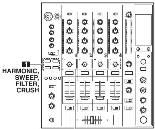
Sound-color effects section
Use to select and enable/disable sound-color effects (P. 17). The button for the selected function will flash, and the effect will be applied equally to channels 1 to 4. When the flashing button is pressed, it lights steadily and the effect turns OFF. When power is first turned on, all effects default to OFF (indicators are lighted).
42. Harmonic Indicators
When [HARMONIC] is turned ON, these indicators light and the color of the indicator changes in accord with the status of the effect (P. 17).
43. Sound-color effect parameter dial (COLOR)
Used to adjust quantitative parameters for the effect selected with the sound-color effect selector buttons (P. 17, 18)
44. Display
See P. 10 to 11 for details.
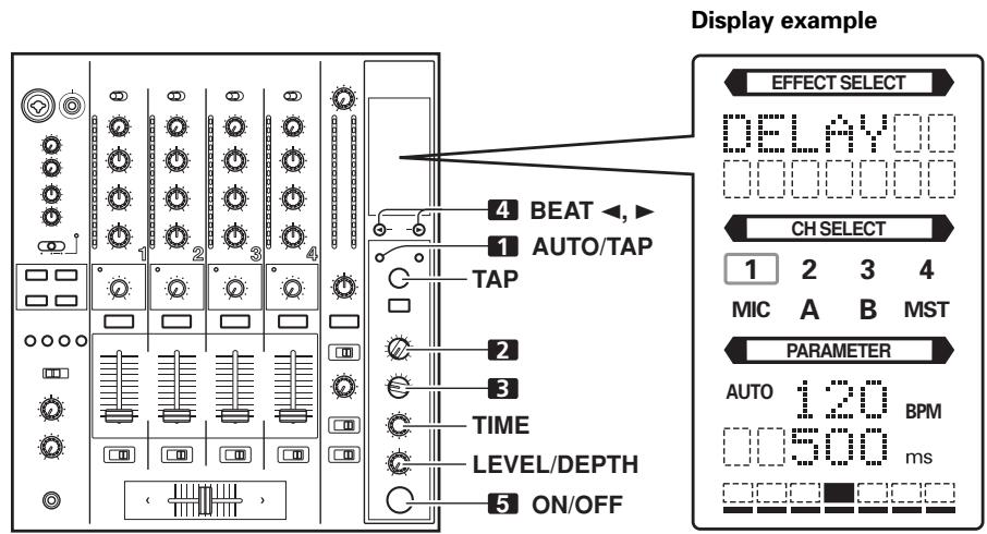
DISPLAY SECTION
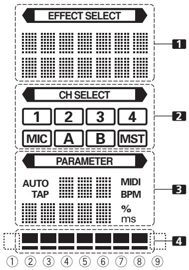
1. Effects display section
The indicator lights constantly, and the alpha-numeric display (seven characters in two lines) indicates the name of the effect as shown below. Also, when one of the change operations is performed as noted in the table, the corresponding characters are displayed for two seconds, after which the display returns to the original effect name.
| Switching Operation | Upper/ Lower Row | Display |
| At MIDI start | Upper | MIDI |
| Lower | START |
| At MIDI stop | Upper | MIDI |
| Lower | STOP |
| MIDI snapshot | Upper | SNAP |
| Lower | SHOT |
2. Channel select display section
The indicator lights constantly, and a red frame lights around the number position corresponding to the chosen effect channel selector.
3. Parameter display section
:
The indicator lights constantly.
AUTO/TAP:
[AUTO] lights when the BPM measuring mode is set to AUTO, and [TAP] lights when the BPM measuring mode is set to manual (TAP).
BPM counter display (3 digits):
In AUTO mode, displays the automatically detected BPM value. If the BPM count cannot be detected automatically, the display will flash at the previously detected value. In manual (TAP) mode, displays the BPM value designated by TAP input, etc.
BPM:
Lights constantly.
MIDI:
Displays the MIDI start/stop status.
- Indicator lights after MIDI start command has been sent.
- Indicator goes out after MIDI stop command has been sent.
Parameter 1 display (5 digits):
Displays parameters designated for each effect. When the beat select buttons (BEAT , ) are pressed, the corresponding beat multiple change is displayed for one second. If the beat select buttons (BEAT , ) are used to designate a value outside the parameter range, the current number will flash but will not change.
Unit Display (% / ms)
Lights in accordance with the unit used for each effect.
4. Beat display section
Displays the location of parameter 1 relative to BPM (1/1 beat). The lower row is lighted constantly. When the parameter 1 location approaches a threshold value, the corresponding indicator is lighted. When the parameter 1 is between threshold values, the indicator flashes. Although the display includes seven actual indicators, the two ends can also be considered to act as indicators, with the result that a theoretical nine positions can be postulated. When the values are at the two ends, no indicators light.
| Effect selector | 1 Effect display | 3 Parameter display | 4 Beat display | |
| Upper/ Lower | Effect name | Minimum value | Maximum value | Default | Unit | ① | ② | ③ | ④ | ⑤ | ⑥ | ⑦ | ⑧ | ⑨ |
| DELAY | Upper | DELAY | 1 | 4 000 | 500 | ms | 1/8 | 1/4 | 1/2 | 3/4 | 1/1 | 2/1 | 4/1 | 8/1 | 16/1 |
| Lower | | |
| ECHO | Upper | ECHO | 1 | 4 000 | 500 | ms | 1/8 | 1/4 | 1/2 | 3/4 | 1/1 | 2/1 | 4/1 | 8/1 | 16/1 |
| Lower | | |
| REV DLY | Upper | REVERSE | 10 | 4 000 | 500 | ms | 1/8 | 1/4 | 1/2 | 3/4 | 1/1 | 2/1 | 4/1 | 8/1 | 16/1 |
| Lower | DELAY | |
| PAN | Upper | PAN | 10 | 16 000 | 500 | ms | 1/16 | 1/8 | 1/4 | 1/2 | 1/1 | 2/1 | 4/1 | 8/1 | 16/1 |
| Lower | | |
| TRANS | Upper | TRANS | 10 | 16 000 | 500 | ms | 1/16 | 1/8 | 1/4 | 1/2 | 1/1 | 2/1 | 4/1 | 8/1 | 16/1 |
| Lower | | |
| FILTER | Upper | FILTER | 10 | 32 000 | 2 000 | ms | 1/4 | 1/2 | 1/1 | 2/1 | 4/1 | 8/1 | 16/1 | 32/1 | 64/1 |
| Lower | | |
| FLANGER | Upper | FLANGER | 10 | 32 000 | 2 000 | ms | 1/4 | 1/2 | 1/1 | 2/1 | 4/1 | 8/1 | 16/1 | 32/1 | 64/1 |
| Lower | | |
| PHASER | Upper | PHASER | 10 | 32 000 | 2 000 | ms | 1/4 | 1/2 | 1/1 | 2/1 | 4/1 | 8/1 | 16/1 | 32/1 | 64/1 |
| Lower | | |
| REVERB | Upper | REVERB | 1 | 100 | 50 | % | 10 | 20 | 30 | 40 | 50 | 60 | 70 | 80 | 90 |
| Lower | | |
| ROBOT | Upper | ROBOT | -100 | 100 | 0 | % | — | -100 | -66 | -50 | 0 | 26 | 50 | 100 | — |
| Lower | | |
| CHORUS | Upper | CHORUS | 10 | 32 000 | 2 000 | ms | 1/4 | 1/2 | 1/1 | 2/1 | 4/1 | 8/1 | 16/1 | 32/1 | 64/1 |
| Lower | | |
| ROLL | Upper | ROLL | 10 | 4 000 | 500 | ms | 1/16 | 1/8 | 1/4 | 1/2 | 1/1 | 2/1 | 4/1 | 8/1 | 16/1 |
| Lower | | |
| REV ROLL | Upper | REVERSE | 10 | 4 000 | 500 | ms | 1/16 | 1/8 | 1/4 | 1/2 | 1/1 | 2/1 | 4/1 | 8/1 | 16/1 |
| Lower | ROLL | |
| SND/RTN | Upper | SEND/ | | | | | | | | | | | | | |
| Lower | RETURN | |
Shaded items are not displayed.
MIXER OPERATIONS
BASIC OPERATIONS
- Set rear panel POWER switch to ON.
-
Set the input selector switch for the desired channel to choose the connected component.
-
When using CD input or LINE input, the connection panel's DIGITAL/CD switch or DIGITAL/LINE switch must be set to [CD] or [LINE].
-
When using a DIGITAL input, the connection panel's DIGITAL/CD switch or DIGITAL/LINE switch must be set to [DIGITAL].
-
Use the TRIM dial to adjust the input level.
- Use the channel equalizer dials (HI, MID, LOW) to adjust the tone.
- Use the channel fader lever to adjust the sound volume of the selected channel.
- To use the cross fader on the selected channel, set the CROSS FADER ASSIGN switch to either cross fader channel A or channel B, and operate the cross fader lever.
- When not using the cross fader, set the CROSS FADER ASSIGN switch to [THRU].
- Use the MASTER LEVEL dial to adjust the overall sound volume.
- Use the BALANCE dial to adjust the sound balance between right and left.
[Selecting Stereo or Monaural]
When the STEREO/MONO switch is set to [MONO], the master output becomes a monaural combination of L+R channels.
- To use a microphone, set the MIC switch to [ON] or [TALK OVER].
- When the switch is set to [TALK OVER], any time a sound of over -15dB is detected by the microphone, the output for all sound sources other than the microphone are attenuated by 20 dB.
- Use the MIC 1 LEVEL dial to adjust the sound volume of MIC 1, and use the MIC 2 LEVEL dial to adjust the sound volume of MIC 2.
- Use the microphone equalizer dials (HI, LOW) to adjust the tone of the microphone sound.
- The microphone equalizer function operates simultaneously on microphone 1 and 2.
[Booth Monitor Output]
- Set the connection panel's MIC SIGNAL switch to select whether microphone sounds are output to the booth monitor.
- When set to the [ADD] position, microphone sounds are output to the booth monitor, and when set to the [CUT] position, microphone sounds are not output to the booth monitor.
- Use the BOOTH MONITOR dial to adjust the sound volume.
- The BOOTH MONITOR dial can be used to adjust the sound volume independently of the MASTER LEVEL dial.
[Headphones Output]
- Use the CUE buttons (channels 1 to 4, MASTER, effector) to select the source.
-
The selected CUE button lights brightly.
-
Set the headphones (MONO SPLIT/STEREO) switch.
-
When set to the [MONO SPLIT] position, the left channel outputs the sound selected with the CUE button, while the right channel outputs the master audio (only when the CUE button for the [MASTER] is ON).
-
When set to the [STEREO] position, the sound corresponding to the selected CUE button is output in stereo.
-
When [MONO SPLIT] is selected, use the MIXING dial to adjust the balance of sound between the left channel (sound selected with the CUE button), and the right channel (the master sound - but only when the CUE button for the [MASTER] is ON).
-
When the MIXING dial is rotated clockwise (toward [MASTER]), the master output (only when the CUE button for the [MASTER] is ON) increases; when rotated counterclockwise (toward [CUE]), the sound selected with the CUE button is output.
-
Use the LEVEL dial to adjust the headphones' sound volume.
[Fader Curve Selection]
The sound volume response to fader operation can be set to one of three characteristic curves.
Use the CH FADER switch to select the desired channel fader response curve.
- At the left setting, the curve operates to produce a rapid rise as the channel fader approaches its distant position.
- At the right setting, the curve operates to produce an even, neutral rise throughout the channel fader's movement.
- At the middle setting, an intermediate curve is produced, midway between the two curves noted above.
- This setting applies equally to channels 1 to 4.
Use the CROSS FADER curve switch to select the cross fader curve response.
- At the left setting, the curve produces a rapid signal rise. (As soon as the cross fader lever leaves the [A] side, the [B] channel sound is produced.)
- At the right setting, the curve operates to produce an even, neutral rise throughout the cross fader's movement.
- At the middle setting, an intermediate curve is produced, midway between the two curves noted above.
- This setting produces equal curve effects for both sides A and B.
FADER START FUNCTION
By connecting the optional Pioneer DJ CD Player control cable, the channel fader and cross fader can be used to start CD playback.
When the mixer's channel fader lever or cross fader lever are moved, the CD player is released from the pause mode and automatically – and instantly – begins playback of the selected track. Also, when the fader lever is returned to its original position, the CD player returns to its cue point (back cue), thus allowing "sampler" type play.
Cross fader start play and back cue play
When the CD player assigned to cross fader channel A is set to standby at a cue point, moving the cross fader lever from the right (B) side toward the left (A) side automatically starts play on the channel A CD player.
When the cross fader lever reaches the left (A) side, the CD player assigned to channel B goes to back cue (returns to cue point). Also, when the CD player assigned to channel B is set to standby at a cue point, moving the cross fader lever from the left (A) side to the right (B) side automatically starts playback on the channel B CD player. When the cross fader lever reaches the right (B) side, the CD player assigned to channel A goes to back cue (returns to cue point).
* The back cue is performed even if the input selector switch is not set to [CD/DIGITAL] or [LINE/DIGITAL].
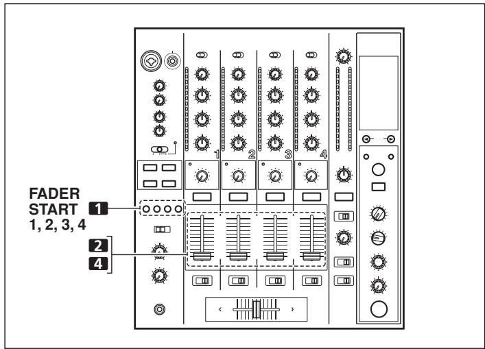
[Using the Channel Fader to Start Playback]
- Press the FADER START button for the channel (1 to 4) connected to the CD player you wish to control.
- The button for the selected channel lights.
- Set the channel fader lever to "0".
- Set the CD player to the desired cue point, and engage cue point standby.
-
If a cue point has already been set, it is not necessary to set the CD player to standby at the cue point.
-
At the instant you wish to start playback, move the channel fader lever.
-
CD player begins playback.
-
After playback has begun, if the channel fader lever is returned to the [0] position, the CD player returns to the cue point and re-enters standby mode (back cue).
-
Playback control is possible with the channel fader only with the CROSS FADER ASSIGN switch is set to [THRU].
[Using the Cross Fader to Start Playback]
-
Press the FADER START button for the channel (1 to 4) connected to the CD player you wish to control.
-
The button for the selected channel lights.
-
Set the CROSS FADER ASSIGN switch for the selected channel to [A] or [B].
-
Select [A] to assign to cross fader channel A (left side).
-
Select [B] to assign to cross fader channel B (right side).
-
Move the cross fader lever to the full opposite side away from the CD player you wish to start.
-
Set the CD player to the desired cue point, and engage cue point standby.
-
If a cue point has already been set, it is not necessary to set the CD player to standby at the cue point.
-
At the instant you wish to start playback, move the cross fader lever.
-
CD player begins playback.
- After playback has begun, if the cross fader lever is moved fully to the opposite side, the CD player assigned to the opposite side channel will return to the cue point and enter standby mode (back cue).
Note:
The fader start function will not be enabled if digital connections are used alone; to use the fader start function, be sure to connect the CD player's analog connectors as well.
EFFECT FUNCTIONS
This unit can produce beat effects linked to the BPM, and sound-color effects linked to the COLOR dials provided for each channel, for a total of 18 basic effects (including [SND/RTN]). In addition, by changing the parameters for each kind of effect, an extremely wide range of effect variations can be produced.
A wide variety of beat effects can be achieved by varying the temporal parameter via the TIME dial (Parameter 1), as well as quantitative parameter via the LEVEL/DEPTH dial (Parameter 2).
Sound-color effect changes can be added by varying the position of the COLOR dials. By combining beat effects and sound-color effects, an even greater range of performance effects can be produced.
TYPES OF BEAT EFFECTS
1. DELAY (One repeat sound)
This function allows a delay sound with beat of 1/8 , 1/4 , 1/2 , 3/4 , 1/1 , 2/1 , 4/1 , 8/1 , or 16/1 to be added quickly and simply. For example, When a 1/2 beat delay sound is added, four beats become eight beats. Also, by adding a 3/4 beat delay sound, the rhythm becomes syncopated.
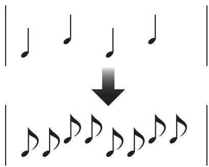
Example
Original (4 beats)
1/2 delay (8 beats)
2. ECHO (Multiple repeat sounds)
This function allows an echo sound with beat of 1/8, 1/4, 1/2, 3/4, 1/1, 2/1, 4/1, 8/1, or 16/1 to be added quickly and simply.
For example, when a 1/1 beat echo sound is used to cutoff the input sound, a sound in synch with the beat is repeated together with fadeout.
Also, by adding a 1/1 beat echo to the microphone, the microphone sound repeats in synch with the music beat.
If a 1/1 beat echo is applied to the vocal portion of a track, the song takes on an effect reminiscent of a "round".
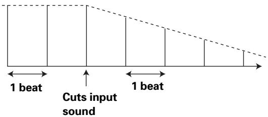
Example
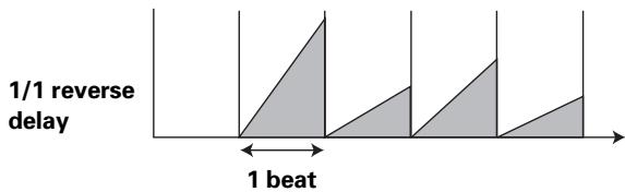
3. REVERSE DELAY (One repeat sound)
This function allows an inverted delay sound with beat of 1/8 , 1/4 , 1/2 , 3/4 , 1/1 , 2/1 , 4/1 , 8/1 , or 16/1 to be added quickly and simply.
Example
4. Auto PAN (L-R BALANCE)
This function distributes sounds in units of 1/16, 1/8, 1/4, 1/2, 1/1, 2/1, 4/1, 8/1, or 16/1 to right and left channels in synch with the rhythm (auto beat pan).
Also, short auto pan can be performed, allowing sounds to be distributed to right/left very quickly, an effect impossible to perform manually.
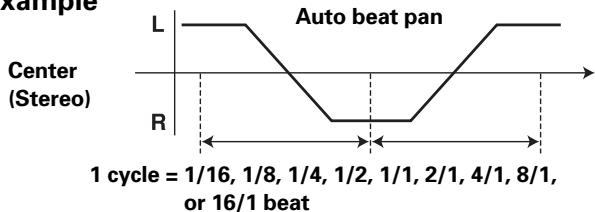
Example
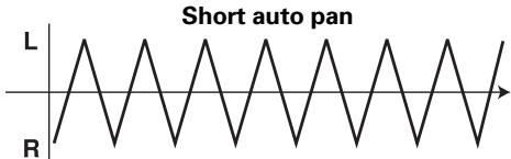
Center (Stereo)
5. Auto TRANS
In units of 1/16 , 1/8 , 1/4 , 1/2 , 1/1 , 2/1 , 4/1 , 8/1 , or 16/1 beat, the sound is automatically cut in synch with the rhythm.
In units of 1/4 , 1/2 , 1/1 , 2/1 , 4/1 , 8/1 , 16/1 , 32/1 , or 64/1 beat, the filter frequency is moved, greatly changing the sound coloration.
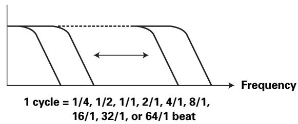
Example
7. FLANGER
In units of 1/4 , 1/2 , 1/1 , 2/1 , 4/1 , 8/1 , 16/1 , 32/1 , or 64/1 beat, 1 cycle of flanger effect is produced quickly and easily.
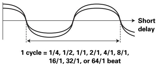
Example
8. PHASER
In units of 1/4 , 1/2 , 1/1 , 2/1 , 4/1 , 8/1 , 16/1 , 32/1 , or 64/1 beat, 1 cycle of phaser effect is produced quickly and easily.
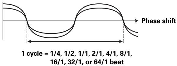
Example
9. REVERB
Produces reverberation effect.
10. ROBOT
Input sounds are reproduced as though generated by a robot.
11. CHORUS
Generates a chorus sound in synch with 1/8 , 1/4 , 1/2 , 1/1 , 2/1 , 4/1 , 8/1 , or 16/1 beat. The sound produced has breadth as though the same pitch were issuing from multiple sources.
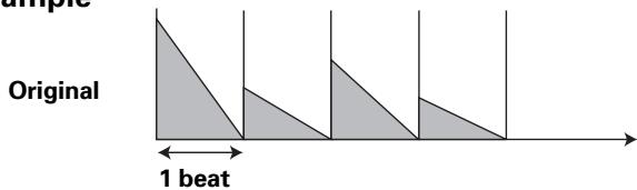
12. ROLL
Sounds of 1/16, 1/8, 1/4, 1/2, 1/1, 2/1, 4/1, 8/1, or 16/1 beat are recorded and output repetitively. Also, when sounds are changed from 1/1 beat to 1/2 or 1/4 in synch with the beat, a roll sound effect can be produced.
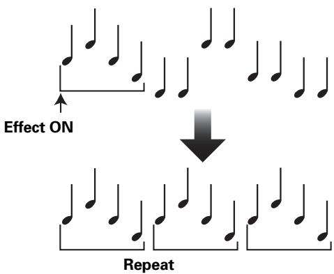
Example
Original
13. REVERSE ROLL
Sounds of 1/16, 1/8, 1/4, 1/2, 1/1, 2/1, 4/1, 8/1, or 16/1 beat are recorded, inverted, and output repetitively. Also, when sounds are changed from 1/1 beat to 1/2 or 1/4 in synch with the beat, an inverted playback roll sound effect can be produced.
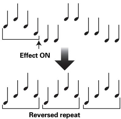
Example
Original
1/1 reverse roll
14. SEND/RETURN
By connecting a sampler or effector, a wide variety of other effects can be created.
PRODUCING BEAT EFFECTS
Effect Name: DELAY
Effect Channel Select: CH 1
BPM value: 120 BPM
Parameter 1:500 ms
Beat multiple: 1/1
Beat effects allow the instant setting of effect times in synch with the BPM (beats per minute), thus allowing the production of a wide variety of effects in synch with the current rhythm, even during live performances.
AUTO: The BPM of the input music signal is detected automatically.
TAP: The BPM is input manually by tapping on the TAP button.
- Whenever power is first turned ON, the function defaults to the [AUTO] mode.
- The indicator for the selected mode [AUTO/TAP] lights in the display.
- In the event the track's BPM cannot be detected automatically, the display's BPM counter will flash.
- The effective range in the AUTO mode is 70 to 180 BPM. It may not be possible to measure some tracks accurately. In this case, use the TAP mode for manual BPM input.
- When BPM mode is set to [AUTO], tapping the TAP button will cause the BPM mode to change to the TAP mode, and the interval at which the TAP button is pressed will be measured.
- When the BPM is set via the TAP button, the beat multiple becomes "1/1" (or "4/1", depending on the effect selected), and the time for 1 beat (1/4 notes) or 4 beats will be set as the effect time.
- If the TIME dial is rotated while depressing the TAP button, direct BPM can be set manually.
If the TIME dial is rotated while holding the TAP button and AUTO/TAP buttons depressed, the BPM can be set in 0.1 units.
2. Set the effect selector to the desired effect.
The display will show the name of the selected effect.
See P. 14 to 15 for details regarding the various effects.
3. Set the effect channel selector to the channel you wish to apply the effect to.
- The display's channel name indicator will show the selected channel with red frame.
- If [MIC] is selected, the effect will be applied to both microphone 1 and microphone 2.
$$
\begin{array}{l} \text {E x a m p l e : W h e n B P M} = 1 2 0 \ 1 / 1 = 5 0 0 \mathrm {m s} \ 1 / 2 = 2 5 0 \mathrm {m s} \ 2 / 1 = 1 0 0 0 \mathrm {m s} \ \end{array}
$$
Each time the button is pressed, the effect alternates ON/OFF (whenever power is first turned ON, the function defaults to OFF).
- The ON/OFF button flashes when the effect is ON.
Parameter 1
Rotating the TIME (PARAMETER 1) dial adjusts the temporal parameter (time) for the selected effect.
See P. 18 for details regarding the effect on parameter 1 of rotating the TIME (PARAMETER 1) dial.
Parameter 2
Rotating the LEVEL/DEPTH (PARAMETER 2) dial adjusts the quantitative parameter for the selected effect.
See P. 18 for details regarding the effect on parameter 2 of rotating the LEVEL/DEPTH (PARAMETER 2) dial.
TYPE OF SOUND-COLOR EFFECT
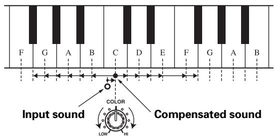
1. HARMONIC
Detects deviation of the input sound from absolute pitch and automatically compensates to the nearest key.
By rotating the dial, the pitch/ key can be adjusted within a range of ± 6 half-tones.
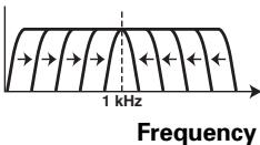
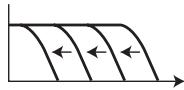
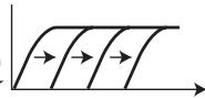
2. SWEEP
This function shifts the frequency of the filter, producing large changes in tone. When the dial is rotated clockwise, the effect produced is that of a band-pass filter, while rotating the dial counterclockwise produces the effect of a notch filter.
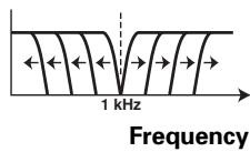
Notch filter

Band pass filter
3. CRUSH
This effect slightly "crushes" the sound, applying a certain accent to the sound.
4. FILTER
The filter frequency is shifted, resulting in strong changes to the tone.
Rotating the dial to the right produces high-pass filter effects, while rotating the dial to the left produces low-pass filter effects.
Low-pass filter
Frequency
High-pass filter
Frequency
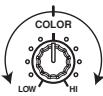
USING SOUND-COLOR EFFECTS
2 COLOR
Sound-color effects are linked to the COLOR effect parameter dial for each channel.
-
Sound-color effects are not applied to microphone inputs.
-
Press the sound-color effect selector buttons (HARMONIC, SWEEP, FILTER, CRUSH) for the desired effect.
HARMONIC:
Applies a pitch-shifted effect matching the track's key.
SWEEP:
The track is passed through the filter and output.
CRUSH:
The track's sound is output in a "crush" effect.
FILTER:
The track is filtered and output.
- The button for the selected effect will flash.
- The selected effect is applied equally to channels 1 to 4.
- If the flashing button is pressed, it lights steadily, and the effect turns OFF.
-
When power is first turned on, all effects default to OFF (indicators are lighted).
-
Use the sound-color effect parameter dial (COLOR) to adjust the quantitative parameter for the effect.
-
The parameter can be adjusted independently for each channel.
- The color of the harmonic indicator changes to indicate the condition of the harmonic effect.
Red: Does not match frequency of key scale.
Green:Matches frequency of key scale.
EFFECT PARAMETERS
Beat Effect
| Name | Beat Switch Parameter | Parameter 1 (TIME dial) | Parameter 2(MIX/DEPTH dial) contents |
| Contents | Setting Range (unit) |
| 1 DELAY | Sets delay time of 1/8 to 16/1 per 1 beat of BPM time. | Sets delay time. | 1 to 4 000 (ms) | Sets balance between original and delay sound. |
| 2 ECHO (*1) | Sets delay time of 1/8 to 16/1 per 1 beat of BPM time. | Sets delay time. | 1 to 4 000 (ms) | Sets balance between original sound and echo sound. |
| 3 REVERSE DELAY | Sets delay time of 1/8 to 16/1 per 1 beat of BPM time. | Sets delay time. | 10 to 4 000 (ms) | Sets balance between original and delay sound. |
| 4 PAN | Sets time of 1/16 to 16/1 per 1 beat of BPM time for distribution to right/left. | Sets effect time. | 10 to 16 000 (ms) | Sets balance between original sound and effect sound. |
| 5 TRANS | Sets cut time of 1/16 to 16/1 per 1 beat of BPM time. | Sets effect time. | 10 to 16 000 (ms) | Sets balance between original sound and effect sound. |
| 6 FILTER | Cycle of cutoff frequency shift is set in unit of 1/4 to 64/1 relative to 1 beat of BPM. | Sets cycle for cutoff time shift. | 10 to 32 000 (ms) | Amount of effect increases when dial is turned clockwise. |
| 7 FLANGER | Cycle of flanger shift is set in units of 1/4 to 64/1 relative to 1 beat of BPM. | Sets cycle for flanger effect shift. | 10 to 32 000 (ms) | Amount of effect increases when dial is turned clockwise. When dial is turned fully counterclockwise, only original sound is output. |
| 8 PHASER | Cycle of phaser effect shift is set in units of 1/4 to 64/1 relative to 1 beat of BPM. | Sets cycle for phase effect shift. | 10 to 32 000 (ms) | Amount of effect increases when dial is turned clockwise. When dial is turned fully counterclockwise, only original sound is output. |
| 9 REVERB (*1) | Amount of reverberation is set from 1 to 100 %. | Sets amount of reverberation effect. | 1 to 100 (%) | Sets balance between original sound and effect sound. |
| 10 ROBOT | Sets pitch of robot sound effect within range of -100 to +100 %. | Sets pitch of robot sound effect. | -100 to +100 (%) | Amount of effect increases when dial is turned clockwise. |
| 11 CHORUS | Cycle of chorus sound waver is set in units of 1/4 to 64/1 relative to 1 beat of BPM. | Sets cycle of chorus sound harmonic. | 10 to 32 000 (ms) | Sets balance of chorus sound. |
| 12 ROLL (*2) | Effect time is set as 1/16 to 16/1 relative of 1 beat of BPM. | Sets effect time. | 1 to 4 000 (ms) | Sets balance of original sound and roll sound. |
| 13 REVERSE ROLL (*2) | Effect time is set as 1/16 to 16/1 relative of 1 beat of BPM. | Sets effect time. | 1 to 4 000 (ms) | Sets balance of original sound and roll sound. |
| 14 SEND/RETURN | — | — | — | Sets volume of RETURN input sound. |
() Even if the effect monitor is turned ON, if no sound is output from the channel to the master output, the effect sound will not be heard.
(^2) When effect is disabled (OFF), the effect sound will not be heard, even if monitor is set to effector.
Sound-color effects
| Name | Parameter (COLOR dial) |
| 1 HARMONIC | Sets amount of pitch shift in range of ±6 half-tones. Rotating dial to right increases pitch shift by +6 half-tones, while rotating to the left reduces pitch shift by -6 half-tones. |
| 2 SWEEP | Sets filter's cutoff frequency. Rotating dial clockwise produces band-pass filter effect; rotating counterclockwise produces notch filter effect. |
| 3 CRUSH | Sets amount of crushing of input sound. Rotate dial counterclockwise to emphasize low-range sounds, and rotate clockwise to emphasize high-range sounds. |
| 4 FILTER | Sets cutoff frequency of filter. Rotating dial to right changes high-pass filter; rotating dial to left changes low-pass filter. |
MIDI SETTINGS
MIDI is an acronym for "Musical Instrument Digital Interface" and refers to a protocol developed for the exchange of data between electronic instruments and computers.
A MIDI cable is used to connect components equipped with MIDI connectors to enable the transmission and receipt of data.
The DJM-800 uses the MIDI protocol for transmitting and receiving data about component operation and BPM (timing clock).
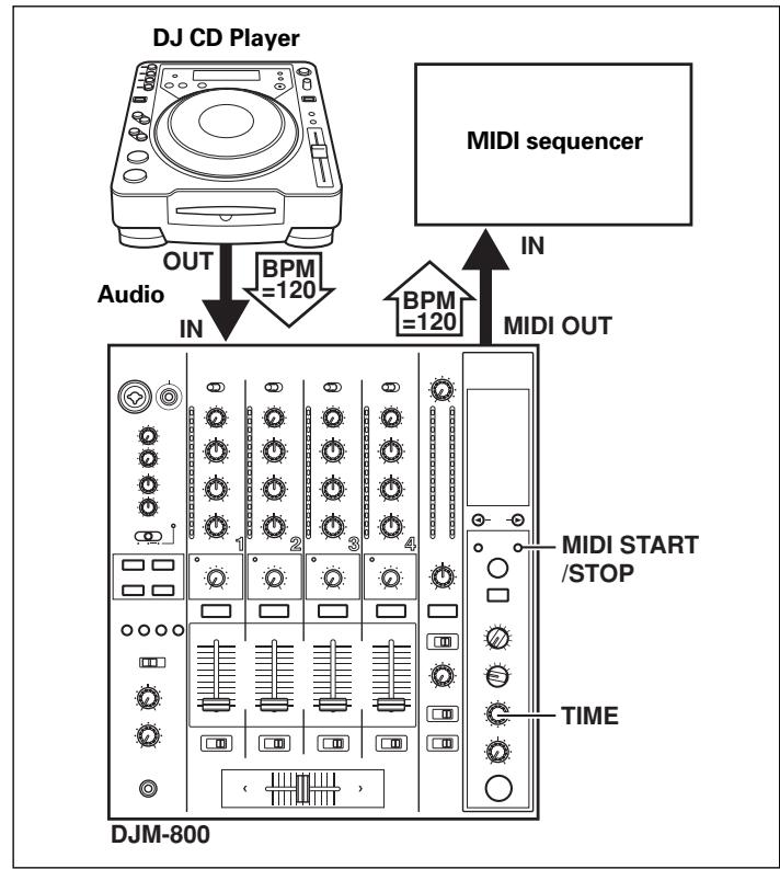
-
Use a commercially available MIDI cable to connect the DJM-800's MIDI OUT connector to the MIDI sequencer's MIDI IN connector.
-
Set the MIDI sequencer's synch mode to "Slave".
- MIDI sequencers that do not support MIDI timing clock cannot be synchronized.
- Synch may not be achieved if the track's BPM cannot be detected and measured stably.
-
BPM values set with the TAP mode can also be used to output the timing clock.
-
Press the MIDI START/STOP button.
-
The MIDI timing clock output range is 40 to 250 BPM.
Note:
- Accurate measuring of BPM may be impossible with some tracks.
[MIDI Channel Setting]
The MIDI channel (1 to 16) can be set and stored in memory.
- While holding the MIDI START/STOP button depressed, set the power switch to ON.
- The display will show [MIDI CH SETTING] and the unit will enter the MIDI setting mode.
- Rotate the TIME dial to select the MIDI channel.
- Press the MIDI START/STOP button.
The selected MIDI channel will be recorded.
- Set power to OFF.
MIDI MESSAGES
| Category | Switch Name | Switch Type | MIDI Message | Comments |
| MSB | LSB |
| CH1 | TRIM | VR | Bn | 01 | dd | | | | 0 to 127 |
| HI | VR | Bn | 02 | dd | | | | 0 to 127 |
| MID | VR | Bn | 03 | dd | | | | 0 to 127 |
| LOW | VR | Bn | 04 | dd | | | | 0 to 127 |
| COLOR | VR | Bn | 05 | dd | | | | 0 to 127 |
| CUE | BUTTON | Bn | 46 | dd | | | | OFF=0, ON=127 |
| FADER | VR | Bn | 11 | dd | | | | 0 to 127 |
| CF ASSIGN | SW | Bn | 41 | dd | | | | 0, 64, 127 |
| CH2 | TRIM | VR | Bn | 06 | dd | | | | 0 to 127 |
| HI | VR | Bn | 07 | dd | | | | 0 to 127 |
| MID | VR | Bn | 08 | dd | | | | 0 to 127 |
| LOW | VR | Bn | 09 | dd | | | | 0 to 127 |
| COLOR | VR | Bn | 0A | dd | | | | 0 to 127 |
| CUE | BUTTON | Bn | 47 | dd | | | | OFF=0, ON=127 |
| FADER | VR | Bn | 12 | dd | | | | 0 to 127 |
| CF ASSIGN | SW | Bn | 42 | dd | | | | 0, 64, 127 |
| CH3 | TRIM | VR | Bn | 0C | dd | | | | 0 to 127 |
| HI | VR | Bn | 0E | dd | | | | 0 to 127 |
| MID | VR | Bn | 0F | dd | | | | 0 to 127 |
| LOW | VR | Bn | 15 | dd | | | | 0 to 127 |
| COLOR | VR | Bn | 16 | dd | | | | 0 to 127 |
| CUE | BUTTON | Bn | 48 | dd | | | | OFF=0, ON=127 |
| FADER | VR | Bn | 13 | dd | | | | 0 to 127 |
| CF ASSIGN | SW | Bn | 43 | dd | | | | 0, 64, 127 |
| CH4 | TRIM | VR | Bn | 50 | dd | | | | 0 to 127 |
| HI | VR | Bn | 51 | dd | | | | 0 to 127 |
| MID | VR | Bn | 5C | dd | | | | 0 to 127 |
| LOW | VR | Bn | 52 | dd | | | | 0 to 127 |
| COLOR | VR | Bn | 53 | dd | | | | 0 to 127 |
| CUE | BUTTON | Bn | 49 | dd | | | | OFF=0, ON=127 |
| FADER | VR | Bn | 14 | dd | | | | 0 to 127 |
| CF ASSIGN | SW | Bn | 44 | dd | | | | 0, 64, 127 |
| CROSS FADER | CROSS FADER | VR | Bn | 0B | dd | | | | 0 to 127 |
| FADER CURVE | CH CURVE | SW | Bn | 5E | dd | | | | 0, 64, 127 |
| CROSS CURVE | SW | Bn | 5F | dd | | | | 0, 64, 127 |
| MASTER | MASTER LEVEL | VR | Bn | 18 | dd | | | | 0 to 127 |
| BALANCE | VR | Bn | 17 | dd | | | | 0 to 127 |
| CUE | BUTTON | Bn | 4A | dd | | | | OFF=0, ON=127 |
| BOOTH | MONITOR | VR | Bn | 19 | dd | | | | 0 to 127 |
| EFFECT | BEAT LEFT | BUTTON | Bn | 4C | dd | | | | OFF=0, ON=127 |
| BEAT RIGHT | BUTTON | Bn | 4D | dd | | | | OFF=0, ON=127 |
| AUTO/TAP | BUTTON | Bn | 45 | dd | | | | OFF=0, ON=127 |
| TAP | BUTTON | Bn | 4E | dd | | | | OFF=0, ON=127 |
| CUE | BUTTON | Bn | 4B | dd | | | | OFF=0, ON=127 |
| EFFECT SELECT | SW | Cn | pc | | | | | See “PROGRAM CHANGE” below. |
| CH SELECT | SW | Cn | pc | | | | |
| TIME | SW | Bn | 0D | MSB | Bn | 2D | LSB | TIME value; FLANGER, PHASER, CHORUS,FILTER changed to 1/2 value; minus values are converted to positive. |
| LEVEL/DEPTH | VR | Bn | 5B | dd | | | | 0 to 127 |
| EFFECT ON/OFF | BUTTON | Bn | 40 | dd | | | | OFF=0, ON=127 |
| MIC(SOUND COLOR FX)(FADER START) | HI | VR | Bn | 1E | dd | | | | 0 to 127 |
| LOW | VR | Bn | 1F | dd | | | | 0 to 127 |
| HARMONIC | BUTTON | Bn | 54 | dd | | | | OFF=0, ON=127 |
| SWEEP | BUTTON | Bn | 55 | dd | | | | OFF=0, ON=127 |
| CRUSH | BUTTON | Bn | 56 | dd | | | | OFF=0, ON=127 |
| FILTER | BUTTON | Bn | 57 | dd | | | | OFF=0, ON=127 |
| 1 | BUTTON | Bn | 58 | dd | | | | OFF=0, ON=127 |
| 2 | BUTTON | Bn | 59 | dd | | | | OFF=0, ON=127 |
| 3 | BUTTON | Bn | 5A | dd | | | | OFF=0, ON=127 |
| 4 | BUTTON | Bn | 5D | dd | | | | OFF=0, ON=127 |
| MIXING | VR | Bn | 1B | dd | | | | 0 to 127 |
| LEVEL | VR | Bn | 1A | dd | | | | 0 to 127 |
| MIDI | START | BUTTON | FA | | | | | | |
| STOP | BUTTON | FC | | | | | | |
PROGRAM CHANGE
| MSB | LSB |
| 0 | 0 | EFFSEL2 | EFFSEL1 | EFFSEL0 | EFFCH2 | EFFCH1 | EFFCHO | |
| EFFECT SEL BEAT |
| EFFSEL2 | EFFSEL1 | EFFSEL0 | |
| 0 | 0 | 1 | DELAY |
| 0 | 1 | 0 | ECHO |
| — | — | — | REV DELAY |
| 0 | 1 | 1 | PAN |
| 1 | 0 | 0 | TRANS |
| 1 | 0 | 1 | FILTER |
| 1 | 1 | 0 | FLANGER |
| 1 | 1 | 1 | PHASER |
| — | — | — | REVERB |
| — | — | — | ROBOT |
| — | — | — | CHORUS |
| — | — | — | ROLL |
| — | — | — | REV ROLL |
| — | — | — | SND/RTN |
| EFFCH2 | EFFCH1 | EFFCH0 | |
| 0 | 0 | 1 | 1 |
| 0 | 1 | 0 | 2 |
| 0 | 1 | 1 | 3 |
| 1 | 0 | 0 | 4 |
| 1 | 0 | 1 | MIC |
| 1 | 1 | 0 | CF.A |
| 1 | 1 | 1 | CF.B |
| — | — | — | MST |
SNAPSHOT
Once the DJM-800 is setup with parameters for a given purpose, that set of parameters can be recorded as a snapshot. When snapshot of the current status is recorded, all messages for control change and program change are transmitted. Hold the MIDI START/STOP button depressed to send the snapshot.
TROUBLESHOOTING
Incorrect operations are often mistaken for trouble and malfunctions. If you think there is something wrong with this component, check the points below. Sometimes the trouble may originate from another component. Thus, also check the other electrical appliances also in use.
If the trouble cannot be rectified even after checking the following items, contact your dealer or nearest PIONEER service center.
| Symptom | Possible Cause | Remedy |
| No power | ·The power cord has not been connected. | ·Connect to power outlet. |
| No sound, or sound volume is too low. | ·Input selector is set incorrectly.
·The rear panel's DIGITAL/CD input selector switch or DIGITAL/LINE input selector switch is set incorrectly.
·Connection cables are connected incorrectly, or connections are loose.
·Jacks or plugs are dirty.
·The rear panel master output attenuator switch (MASTER ATT) is set to -12 dB, etc. | ·Set input selector to playback component.
·Set the rear panel's DIGITAL/CD input selector switch or DIGITAL/LINE input selector switch to match the component being played.
·Connect correctly.
·Clean soiled jacks/plugs before connecting.
·Adjust rear panel master attenuator switch (MASTER ATT). |
| Microphone sound isn't produced in BOOTH output. | ·The rear panel's MIC SIGNAL switch is set to [CUT]. | ·Set rear panel's MIC SIGNAL switch to [ADD]. |
| No digital output. | ·The digital output sampling frequency (fs) does not match the specifications of the connected component. | ·Set rear panel sampling frequency selector to match the specifications of the connected component. |
| Sound is distorted. | ·Master output level is too high.
·Input level is too high. | ·Adjust master output level (MASTER LEVEL) dial or the rear panel master output attenuator (MASTER ATT) switch.
·Adjust the TRIM dial so that the input level approaches 0 dB on the channel level indicator. |
| Cross fader doesn't work. | ·CROSS FADER ASSIGN switch setting ([A], [THRU], [B]) is incorrect. | ·Correctly set the CROSS FADER ASSIGN switch for the desired channel. |
| Can't perform fader start with CD player. | ·The FADER START button is set to OFF.
·Rear panel CONTROL jack is not connected to CD player.
·Only the rear panel CONTROL jack is connected to the CD player. | ·Set the FADER START button to ON.
·Use a control cable to connect the CONTROL jacks of mixer and CD player.
·Connect both the CONTROL jacks and analog input connectors. |
| Effects don't work. | ·Effect channel selector setting is incorrect.
·Effect parameter 2 adjust dial (LEVEL/DEPTH) is set to [MIN]. | ·Correctly select the channel on which you wish to apply effects.
·Adjust the effect parameter 2 adjust dial (LEVEL/DEPTH). |
| External effector doesn't work. | ·Effect selector is not set to [SND/RTN].
·Effector is not connected to rear panel SEND/RETURN connector.
·Effect channel selector is set to incorrectly. | ·Set effect selector to [SND/RTN].
·Connect effector to the rear panel SEND/RETURN connectors.
·Use the effect channel selector to select the audio source to which you wish to apply the effects. |
| Sound from external effector is distorted. | ·Input level from external effector is set too high. | ·Lower the output level of the external effector. |
| BPM can't be measured. Measured BPM value is incorrect. | ·Input level is too high, or too low.
·BPM may not be correctly measurable with some tracks. | ·Adjust the TRIM dial so that the input level approaches 0 dB in the channel level indicator.
·Adjust other channels as well so that the input levels approach 0 dB in the channel level indicator.
·Strike the TAP button to set BPM manually. |
| The measured BPM value is different from the value published with the CD. | ·Some differences may occur due to differences in BPM detection methods. | ·No remedy is necessary. |
| MIDI sequencer can't be synchronized. | ·MIDI sequencer's synch mode is not set to "slave".
·MIDI sequencer is not supported type. | ·Set MIDI sequencer's sync mode to "slave".
·MIDI sequencers that do not support MIDI timing lock cannot be synchronized. |
Static electricity or other external interference may cause the unit to malfunction. To restore normal operation, turn the power off and then on again.
SPECIFICATIONS
1. General
Power source AC 220 V to 240 V, 50 Hz/60 Hz
Power consumption 30 W
Operating temperature +5^ to +35^
Operating humidity 5% to 85% (without condensation)
Weight 7.5 kg
Maximum dimensions 320 (W) × 381 (D) × 108 (H) mm
2. Audio section
Sampling rate 96 kHz
A/D, D/A converter 24 bits
Frequency response
LINE 20 Hz to 20 kHz
MIC 20 Hz to 20 kHz
PHONO 20 Hz to 20 kHz (RIAA)
S/N ratio (at rated output)
LINE 104 dB
PHONO 88 dB
MIC 84 dB
Distortion (LINE-MASTER 1) .0.005 %
Standard input level/Input impedance
PHONO 2 to 4 -52 dBu/47 kΩ
MIC 1, MIC 2 -52 dBu/3 kΩ
LINE, LINE/CD 1 to 4 -12 dBu/22 kΩ
RETURN -12 dBu/22 kΩ
Standard output level/Load impedance/Output impedance
MASTER 1 +2 dBu/600 Ω/10 Ω or less
MASTER 2 +2 dBu/10 kΩ/1 kΩ
REC -8 dBu/10 kΩ/1 kΩ
BOOTH +2 dBu/600 Ω/600 Ω
SEND -12 dBu/10 kΩ/1 kΩ
PHONES +8.5 dBu/32 Ω/22 Ω or less
Rated output level/Load impedance
MASTER 1 +22 dBu/600 Ω
MASTER 2 +20 dBu/10 kΩ
Crosstalk (LINE) 88 dB
Channel equalizer response
HI. -26 dB to +6 dB (13 kHz)
MID -26 dB to +6 dB (1 kHz)
LOW -26 dB to +6 dB (70 Hz)
Microphone equalizer response
HI. -12 dB to +6 dB (10 kHz)
LOW. -12 dB to +6 dB (100 Hz)
PHONO input connectors
RCA pin jacks 3
LINE/CD input connectors
RCA pin jacks 4
LINE input connectors
RCA pin jacks 1
MIC input connectors
XLR connector/phone jack (Ø6.3 mm) 1
Phone jack (Ø6.3 mm) 1
DIGITAL coaxial input connectors
RCA pin jacks 4
RETURN input connectors
Phone jacks (06.3 mm) 1
MASTER output connectors
XLR connectors 1
RCA pin jacks 1
BOOTH output connectors
Phone jacks (06.3 mm) 1
REC output connectors
RCA pin jacks 1
SEND output connectors
Phone jacks (06.3 mm) 1
DIGITAL coaxial output connector
RCA pin jack 1
MIDI OUT connector
5P DIN 1
PHONES output connector
Stereo phone jack (Ø6.3 mm) 1
CONTROL connector
Mini phone jacks (03.5 mm) 4
4. Accessories
Operating Instructions 1
Power cord 1
Specifications and appearance are subject to change without notice.
FONCTIONS DES EFFETS 35
TYPES D'EFFETS DE BATTEMENT 35
PRODUCTION D'EFFETS DE BATTEMENT 37
TYPE D'EFFETS DE COULEUR SONORE 38
UTILISATION DES EFFETS DE COULEUR DE SON 38
PARAMÉTRES DES EFFETS 39
RÉGLAGES MIDI 40
SYNCHRONISATION DES SIGNAUX AUDIO A
UN SEQUENCEUR EXTERNE, OU UTILISATION
DES INFORMATIONSDU DJM-800POUR
CONTROLLER UN SEQUENCEUR EXTERNE .... 40
MESSAGESMIDI 40
CHANGEMENT DE PROGRAMME 41
SNAPSHOT (INSTANTANÉ) 41
DIVERS
GUIDE DE DÉPANNAGE 42
FICHE TECHNIQUE 43
SCHEMA DE PRINCIPLE 128
VÉRIFICATION DES ACCESSOIRES
PUPITRE D'EXPLOitation
CD/DIGITAL (canal 2) :
FONCTIONS DES EFFETS
Distorsion (LINE-MASTER 1) .005%
Fra gli effetti, ricordiamo delay, echo, reverse delay, pan, trance, filter, flanger, phaser, reverb, robot, chorus, roll e reverse roll.
Distorsione (LINE-MASTER 1) .005%
WAARSCHUWING NETSNOER
40. Effecttoets/indicator (ON/OFF)
BPM tellerdisplay (3 cijfers):
[Kiezen van stereo of mono]
④ Entrada/salida digital (IN/OUT)
Laitters correspond to the data of the data set. The data set is a list of all the data that are used in the analysis.
Estamericanidad de la Universidad de Mexico (Universidad de Mexico) es un instrumento de la Universidad de Mexico. La Universidad de Mexico is a research center for the study of the molecular and structural properties of proteins, including protein structure, function, and folding. The University of Washington (WUW) is a state-funded research institute that focuses on protein structure and function in the human brain.
HI. -12 dB a +6 dB (10 kHz)
LOW. -12 dB a +6 dB (100 Hz)
Conector de salute coaxial DIGITAL
Published by Pioneer Corporation.
Copyright © 2005 Pioneer Corporation.
All rights reserved.