
DJM-400 - Mixer PIONEER - Free user manual and instructions
Find the device manual for free DJM-400 PIONEER in PDF.

| Product type | DJ mixer |
| Brand | Pioneer |
| Model | DJM-400 |
| Dimensions (W × D × H) | 223 × 304.7 × 106.6 mm |
| Weight | 3.2 kg |
| Power supply | Mains 220-240 V, 50/60 Hz, 13 W |
| Audio inputs | 2 x PHONO/LINE (RCA), 2 x CD (RCA), 2 x MIC/AUX (6.35 mm jack) |
| Audio outputs | 2 x MASTER OUT (RCA), 1 x PHONES (6.35 mm stereo jack) |
| Control connectors | 2 x CONTROL (3.5 mm mini-jack) for Pioneer DJ CD players |
| Audio quality | 96 kHz/24-bit sampling, 32-bit DSP |
| Per-channel EQ | 3-band (HI, MID, LOW) with Kill function (-∞) |
| Built-in effects | Delay, Echo, Filter, Flanger, Phaser, Robot, Roll, In-loop Sampler |
| Special features | Fader Start, automatic Talk-over, auto/TAP BPM counter, crossfader curve selector |
| Frequency response (LINE) | 20 Hz - 20 kHz |
| Signal-to-noise ratio (LINE) | 97 dB |
| Distortion (LINE-MASTER OUT) | 0.007% |
| Maintenance and cleaning | Soft dry cloth or slightly dampened with diluted neutral detergent. Do not use thinners, benzene, or insecticides. |
| Safety | Do not expose to moisture or naked flames. Leave at least 5 cm at the rear and 3 cm on the sides for ventilation. Unplug the power cord if not used for extended periods. |
| Operating temperature | +5°C to +35°C, relative humidity < 85% |
| Supplied accessories | Power cord, instruction manual |
Frequently Asked Questions - DJM-400 PIONEER
User questions about DJM-400 PIONEER
0 question about this device. Answer the ones you know or ask your own.
Ask a new question about this device
Download the instructions for your Mixer in PDF format for free! Find your manual DJM-400 - PIONEER and take your electronic device back in hand. On this page are published all the documents necessary for the use of your device. DJM-400 by PIONEER.
USER MANUAL DJM-400 PIONEER
Operating Instructions
Mode d'emploi
Bedienungsanleitung
Thank you for buying this Pioneer product.
Please read through these operating instructions so you will know how to operate your model properly. After you have finished reading the instructions, put them away in a safe place for future reference.
In some countries or regions, the shape of the power plug and power outlet may sometimes differ from that shown in the explanatory drawings. However the method of connecting and operating the unit is the same.
IMPORTANT

The lightning flash with arrowhead symbol, within an equilateral triangle, is intended to alert the user to the presence of uninsulated "dangerous voltage" within the product's enclosure that may be of sufficient magnitude to constitute a risk of electric shock to persons.
CAUTION
RISK OF ELECTRIC SHOCK DO NOT OPEN

CAUTION:
TO PREVENT THE RISK OF ELECTRIC SHOCK,DO NOT REMOVE COVER (OR BACK).NO USER-SERVICEABLE PARTS INSIDE.REFER SERVICING TO QUALIFIED SERVICE PERSONNEL.
The exclamation point within an equilateral triangle is intended to alert the user to the presence of important operating and maintenance (servicing) instructions in the literature accompanying the appliance.
D3-4-2-1-1 En-A
Replacement and mounting of an AC plug on the power supply cord of this unit should be performed only by qualified service personnel.
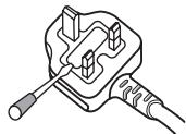
IMPORTANT: THE MOULDED PLUG
This appliance is supplied with a moulded three pin mains plug for your safety and convenience. A 5 amp fuse is fitted in this plug. Should the fuse need to be replaced, please ensure that the replacement fuse has a rating of 5 amps and that it is approved by ASTA or BSI to BS1362.
Check for the ASTA mark or the BSI mark on the body of the fuse.
If the plug contains a removable fuse cover, you must ensure that it is refitted when the fuse is replaced. If you lose the fuse cover the plug must not be used until a replacement cover is obtained. A replacement fuse cover can be obtained from your local dealer.
If the fitted moulded plug is unsuitable for your socket outlet, then the fuse shall be removed and the plug cut off and disposed of safely. There is a danger of severe electrical shock if the cut off plug is inserted into any 13 amp socket.
If a new plug is to be fitted, please observe the wiring code as shown below. If in any doubt, please consult a qualified electrician.
IMPORTANT: The wires in this mains lead are coloured in accordance with the following code:
Blue: Neutral Brown:Live
As the colours of the wires in the mains lead of this appliance may not correspond with the coloured markings identifying the terminals in your plug, proceed as follows ;
The wire which is coloured BLUE must be connected to the terminal which is marked with the
letter N or coloured BLACK
The wire which is coloured BROWN must be connected to the terminal which is marked with the
letter L or coloured RED
How to replace the fuse: Open the fuse compartment with a screwdriver and replace the fuse.
D3-4-2-1-2-B_En
Operating Environment
Operating environment temperature and humidity: +5°C + + 35°C(+41°F + + 95°F) less than 85% R (cooling vents not blocked)
Do not install this unit in a poorly ventilated area, or in locations exposed to high humidity or direct sunlight (or strong artificial light) D3-4-2-1c_A_En
WARNING
To prevent a fire hazard, do not place any naked flame sources (such as a lighted candle) on the equipment. D3-4-2-1-7a
WARNING
Before plugging in for the first time, read the following section carefully.
The voltage of the available power supply differs according to country or region. Be sure that the power supply voltage of the area where this unit will be used meets the required voltage (e.g., 230V or 120V) written on the rear panel. D3-4-2-1-4_A_En

If you want to dispose this product, do not mix it with general household waste. There is a separate collection system for used electronic products in accordance with legislation that requires proper treatment, recovery and recycling.
Private households in the 25 member states of the EU, in Switzerland and Norway may return their used electronic products free of charge to designated collection facilities or to a retailer (if you purchase a similar new one). For countries not mentioned above, please contact your local authorities for the correct method of disposal. By doing so you will ensure that your disposed product undergoes the necessary treatment, recovery and recycling and thus prevent potential negative effects on the environment and human health.
If the AC plug of this unit does not match the AC outlet you want to use, the plug must be removed and appropriate one fitted. Replacement and mounting of an AC plug on the power supply cord of this unit should be performed only by qualified service personnel. If connected to an AC outlet, the cut-off plug can cause severe electrical shock. Make sure it is properly disposed of after removal. The equipment should be disconnected by removing the mains plug from the wall socket when left unused for a long period of time (for example, when on vacation). D3-4-2-2-1a_A_En
CAUTION
The POWER switch on this unit will not completely shut off all power from the AC outlet. Since the power cord serves as the main disconnect device for the unit, you will need to unplug it from the AC outlet to shut down all power. Therefore, make sure the unit has been installed so that the power cord can be easily unplugged from the AC outlet in case of an accident. To avoid fire hazard, the power cord should also be unplugged from the AC outlet when left unused for a long period of time (for example, when on vacation). D3-4-2-2-2a_A_En
WARNING
This equipment is not waterproof. To prevent a fire or shock hazard, do not place any container filed with liquid near this equipment (such as a vase or flower pot) or expose it to dripping, splashing, rain or moisture. D3-4-2-1-3.A.Er
VENTILATION CAUTION
When installing this unit, make sure to leave space around the unit for ventilation to improve heat radiation (at least 5 cm at rear, and 3 cm at each side).
WARNING
Slots and openings in the cabinet are provided for ventilation to ensure reliable operation of the product, and to protect it from overheating. To prevent fire hazard, the openings should never be blocked or covered with items (such as newspapers, table-cloths, curtains) or by operating the equipment on thick carpet or a bed. D3-4-2-1-7b_A_En
This product complies with the Low Voltage Directive (73/23/EEC, amended by 93/68/EEC), EMC Directives (89/336/EEC, amended by 92/31/EEC and 93/68/EEC). D3-4-2-1-9a_En
POWER-CORD CAUTION
Handle the power cord by the plug. Do not pull out the plug by tugging the cord and never touch the power cord when your hands are wet as this could cause a short circuit or electric shock. Do not place the unit, a piece of furniture, etc., on the power cord, or pinch the cord. Never make a knot in the cord or tie it with other cords. The power cords should be routed such that they are not likely to be stepped on. A damaged power cord can cause a fire or give you an electrical shock. Check the power cord once in a while. When you find it damaged, ask your nearest PIONEER authorized service center or your dealer for a replacement. S002_En
CAUTIONS REGARDING HANDLING
Location
Install the unit in a well-ventilated location where it will not be exposed to high temperatures or humidity.
- Do not install the unit in a location which is exposed to direct rays of the sun, or near stoves or radiators. Excessive heat can adversely affect the cabinet and internal components. Installation of the unit in a damp or dusty environment may also result in a malfunction or accident. (Avoid installation near cookers etc., where the unit may be exposed to oily smoke, steam or heat.)
- When the unit is used inside a carrying case or DJ booth, separate it from the walls or other equipment to improve heat radiation.
Cleaning the Unit
- Use a polishing cloth to wipe off dust and dirt.
- When the surfaces are very dirty, wipe with a soft cloth dipped in some neutral cleanser diluted five or six times with water and wrung out well, then wipe again with a dry cloth. Do not use furniture wax or cleaners.
- Never use thinners, benzene, insecticide sprays or other chemicals on or near this unit, since these will corrode the surfaces.
CONTENTS
CAUTIONS REGARDING HANDLING 2
SPECIFICATIONS 3
FEATURES 3
BEFORE USING
CONNECTIONS 4
CONNECTION PANEL 4
CONNECTING INPUTS 5
CONNECTING OUTPUTS 5
CONNECTING THE POWER CORD 5
NAMES AND FUNCTIONS OF PARTS 6
OPERATIONS
MIXER OPERATIONS 8
BASIC OPERATIONS 8
FADER START FUNCTION 9
EFFECT FUNCTIONS 10
TYPES OF BEAT EFFECTS 10
PRODUCING BEAT EFFECTS 11
IN-LOOP SAMPLER 11
EFFECT PARAMETERS 12
OTHER
TROUBLESHOOTING 13
BLOCKDIAGRAM 76
SPECIFICATIONS
1.General
Power source AC 220 V to 240 V, 50 Hz/60 Hz
Power consumption 13 W
Operating temperature +5°C to +35°C
Operating humidity 5% to 85% (without condensation)
Weight 3.2 kg
Maximum dimensions 223 (W) × 304.7 (D) × 106.6 (H) mm
2. Audio section
Sampling rate 96 kHz
A/D, D/A converter 24 bits
Frequency response
LINE 20 Hz to 20 kHz
MIC 20 Hz to 20 kHz
PHONO 20 Hz to 20 kHz (RIAA)
S/N ratio (at rated output)
LINE 97 dB
PHONO 82 dB
MIC 78 dB
Distortion (LINE-MASTER OUT) 0.007 %
Input level/ Impedance
PHONO -52 dBu/47 kΩ
MIC 1, MIC 2 -52 dBu/47 kΩ
CD, LINE -12 dBu/47 kΩ
Output Level/Impedance
MASTER OUT +2 dBu/10 kΩ
PHONES +2dBu/32Ω
Crosstalk (LINE) 78 dB
Channel equalizer response (Isolater)
HI. +9 dB to -∞ (13 kHz)
MID +9 dB to -∞ (1 kHz)
LOW +9 dB to -∞ (70 Hz)
Microphone equalizer response
HI. -12 dB (full counterclockwise) to 0 dB (center) (10 kHz)
LOW -12 dB (full clockwise) to 0 dB (center) (100 Hz)
3. Input/output connector systems
PHONO/LINE input connectors
RCA pin jacks 2
CD input connectors
RCA pin jacks 2
MIC/AUX input connectors
Phone jacks (6.3 mm) 2
MASTER output connectors
RCA pin jacks 2
PHONES connectors
Stereo phone jack (Ø6.3 mm) 1
CONTROL connectors
Mini-phone jacks (03.5 mm) 2
4. Accessories
Operating Instructions 1
Power cord 1
Specifications and appearance are subject to change without notice.
FEATURES
① Designed for high sound quality
Analog signals are sampled at 96 kHz/24-bit, comparable to professional performance levels. Mixing is performed with the same type of 32-bit DSP as used in the DJM-1000 and DJM-800, thus eliminating any loss in fidelity, and producing clear and powerful club sound optimally suited for DJ play.
(2) 3-band equalizer with kill function
Equalizer functions are provided for each of the three bandwidths HI, MID, and LOW, and a kill function is provided to drop the attenuation level to -∞ .
③ Wide variety of effects
1) Beat effects
The "beat effects" so popular on the DJM-600 have been given further evolution. Effects can be applied in linkage to the BPM (Beats Per Minute) count, thus allowing the production of a variety of sounds. Some of the effects include delay, echo, filter, flanger, phaser, robot, and roll.
2) Beat select buttons
Automatically set the effect time linked to the BPM. Allows selection of desired BPM for synchronizing beat effects.
3) IN-LOOP sampler
Detects the current track's BPM and records up to 5 of 4-beat sources in banks, and plays a loop in time with the track's BPM.
④ 2 MIC input, AUX switching
Equipped with 2 MIC input jacks that can be switched to AUX, allowing use as a third LINE input.
⑤ Auto talk-over
The auto talk-over function automatically reduces track volume when microphone input is detected.
Other functions
- A control cable can be used to connect the unit to a Pioneer DJ CD player, thus allowing playback to be linked to operation of the fader ("fader start play").
- "Fader curve adjustment" function allows modification of the cross fader curves.
- "Auto BPM counter" provides visual representation of a track's tempo.
- Monitor auto assignment function can be used to assign channel inputs and master outputs to the left and right channels of monitor headphones.
- Full lineup of input/output systems. Provided with two each of CD and LINE/PHONO (MM type) inputs and two microphone inputs for a total of six input systems, together with two output systems.
CONNECTIONS
CONNECTION PANEL
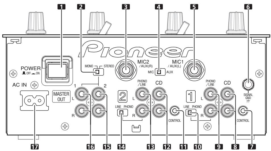
Rear panel
Front panel
1. POWER switch
2. STEREO/MONO selector switch
When switch is set to the [MONO] position, master output is in monaural.
3. MIC2/AUX(R) input connector
Ø6.3 mm phone-type input connector. Use for microphone input, or for right (R) channel of component with line level output.
4. MIC/AUX input selector switch
When this switch is set to [AUX], the MIC1 and MIC2 input connectors function as AUX(L) and AUX(R) input connectors.
5. MIC1/AUX(L) input connector
Ø6.3 mm phone-type input connector. Use for microphone input, or for left (L) channel of component with line level output.
6. Signal grounding terminal (SIGNAL GND)
Use to connect ground wires from analog players.
This is not a safety grounding terminal.
7. Channel 1 CONTROL connector
Ø3.5 mm mini-phone type connector. Connect to control connector of the DJ CD player connected to channel 1 inputs.
When this connection is made, the DJ mixer's fader lever can be used to perform fader start play and back cue on the channel 1 DJ CD player.
8. Channel 1 CD input connectors (CD)
RCA type line level input connectors.
Use to connect a DJ CD player or other component with line level output.
9. Channel 1 PHONO/LINE input connectors
RCA type phono level (for MM cartridge) or line level input connectors.
Select function using channel 1 PHONO/LINE selector switch.
10. Channel 1 PHONO/LINE selector switch
Use to select function of channel 1 PHONO/LINE input connectors.
11. Channel 2 CONTROL connector
03.5 mm mini-phone type connector. Connect to control connector of the DJ CD player connected to channel 2 inputs.
When this connection is made, the DJ mixer's fader lever can be used to perform fader start play and back cue on the channel 2 DJ CD player.
12. Channel 2 CD input connectors (CD)
RCA type line level input connectors.
Use to connect a DJ CD player or other component with line level output.
13. Channel 2 PHONO/LINE input connectors
RCA type phono level (for MM cartridge) or line level input connectors.
Select function using channel 2 PHONO/LINE selector switch.
14. Channel 2 PHONO/LINE selector switch
Use to select function of channel 2 PHONO/LINE input connectors.
15. MASTER OUT 2 output connectors
RCA type unbalanced output.
16. MASTER OUT 1 output connectors
RCA type unbalanced output.
17. Power inlet (AC IN)
Use the accessory power cord to connect to an AC power outlet of the proper voltage.
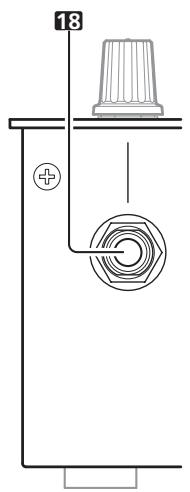
18. Headphones jack (PHONES)
Use to connect stereo headphones equipped with 6.3 mm stereo headphones plug.
Always turn off the power switch and disconnect the power plug from its outlet when making or changing connections.
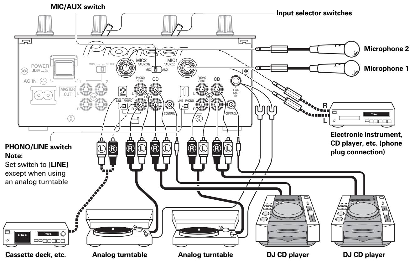
CONNECTING INPUTS
Pioneer DJ CD players
Connect a DJ CD player's audio output connectors to one of the channel 1 to 2 CD input connectors, and connect the player's control cable to the corresponding channel's CONTROL connector.
Set the connected channel's input selector switch to [CD].
Analog turntable
To connect an analog turntable, connect the turntable's audio output cable to one of the channel 1 to 2 PHONO/LINE input connectors. Set the corresponding channel's PHONO/LINE switch to [PHONO], and set the channel's input selector switch to [PHONO/LINE]. The DJM-400's PHONO inputs support MM cartridges. Connect the turntable's ground wire to the DJM-400's SIGNAL GND terminal.
Connecting other devices with line level output
To use a cassette deck or other CD player, connect the component's audio output connectors to one of the channel 1 to 2 PHONO/LINE input connectors. Then set the corresponding channel's PHONO/ LINE switch to [LINE], and the input selector switch to [PHONO/LINE].
Microphone
The MIC1 and MIC2 jacks can be used to connect microphones with φ 6.3 mm phone plugs. Set MIC/AUX switch to [MIC] position.
Auxiliary input connectors
The MIC1 and MIC2 JACKS can also be used together as a pair of stereo line input connectors to connect a component equipped with line level output connectors. Connect the component's L channel to MIC1 (AUX(L)) jack and the R channel to the MIC2 (AUX(R)) jack. Then set the MIC/AUX switch to [AUX] (this connection requires the use of 6.3 mm phone plugs).
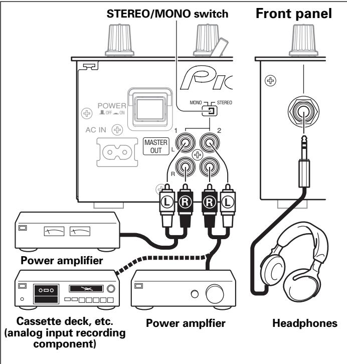
CONNECTING OUTPUTS
Master output
This unit is furnished with MASTER OUT 1 and MASTER OUT 2 output systems, both of which support the use of RCA plugs. If the unit's STEREO/MONO switch is set to [MONO], the master output will be a monaural combination of L+R channels.
Headphones
The front panel PHONES jack can be used to connect headphones with a 06.3 mm stereo phone plug.
Connect the power cord last.
- After completing all other connections, connect the accessory power cord to the AC inlet on the back of the player, then connect the plug to a standard wall outlet or to the auxiliary power outlet of your amplifier.
- Use only the supplied power cord.
NAMES AND FUNCTIONS OF PARTS
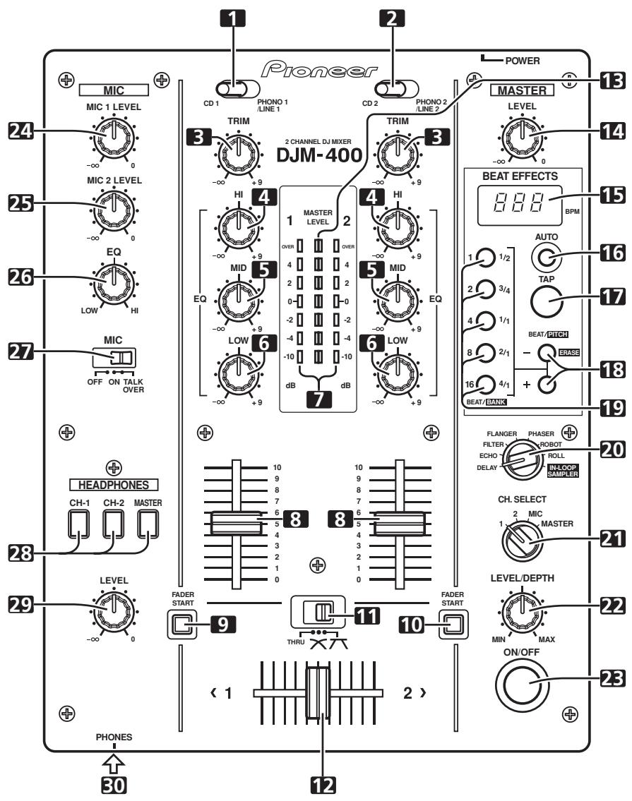
1 Channel 1 input selector switch
CD 1:
The CD input connectors (line level input) are selected.
PHONO 1/LINE 1:
PHONO/LINE input connectors are selected.
- The connection panel's PHONO/LINE switch is used to switch the function of the channel 1 connectors between phonograph input (analog turntable input) and line input (line level input).
2 Channel 2 input selector switch
CD 2:
The CD input connectors (line level input) are selected.
PHONO 2/LINE 2:
PHONO/LINE input connectors are selected.
- The connection panel's PHONO/LINE switch is used to switch the function of the channel 2 connectors between phonograph input (analog turntable input) and line input (line level input).
3 TRIM adjust dial
Use to adjust the input level for each channel. (Adjustable range: -∞ to +9 dB, mid-position is about 0 dB)
4 Channel equalizer high-range adjust dial (HI)
Use to adjust the treble (high-range) frequency sound for each channel (includes kill function). (Adjustable range: -∞ to +9 dB)
5 Channel equalizer mid-range adjust dial (MID)
Use to adjust the mid-range frequency sound for each channel (includes kill function). (Adjustable range: -∞ to +9 dB)
6 Channel equalizer low-range adjust dial (LOW)
Use to adjust the bass (low-range) frequency sound for each channel (includes kill function). (Adjustable range: -∞ to +9 dB)
7 Channel level indicators
Display the current level for each channel, with 0.6 second peak hold.
8 Channel fader levers
Use to adjust sound volumes for each channel. (Adjustable range: -∞ to 0 dB)
9 Channel 1 fader start button/indicator (FADER START)
Pressing this button toggles ON/OFF, the fader start/ back cue function for the DJ CD player connected to channel 1. The button lights when set to ON. When set to ON, the operation differs depending on the setting of the cross fader selector switch.
-
When the cross fader selector switch is at the left (THRU) position, the function is linked to the operation of the channel fader lever (not linked to cross fader).
-
When the cross fader selector switch is at the middle (×) or right (π) position, the function is linked to the cross fader lever (not linked to channel fader).
10 Channel 2 fader start button/ indicator (FADER START)
Pressing this button toggles ON/OFF, the fader start/ back cue function for the DJ CD player connected to channel 2. The button lights when set to ON. When set to ON, the operation differs depending on the setting of the cross fader selector switch.
-
When the cross fader selector switch is at the left (THRU) position, the function is linked to the operation of the channel fader lever (not linked to cross fader).
-
When the cross fader selector switch is at the middle (×) or right (π) position, the function is linked to the cross fader lever (not linked to channel fader).
11 Cross fader selector switch
Select whether or not to use the cross fader, and to select from two types of curve response.
- When the switch is set to left (THRU) position, the cross fader is disabled, and the channel fader output is mixed without passing through the cross fader.
- When this switch is set to the center (×) position, the cross fader is enabled, and a slowly rising curve response is selected.
- When set to the right position 广 , the cross fader is enabled, and a rapidly rising curve response is selected (as soon as the lever leaves the [ 1] side, the [2 > ] sound is heard).
12 Cross fader lever
Outputs channel 1 and channel 2 sounds in accordance with cross fader curve response selected with the cross fader selector switch. The cross fader function is disabled when the cross fader selector switch is set to the [THRU] position.
13 Master level indicators (MASTER LEVEL)
These indicators show the master output level in a monaural display. Each indicator has a 0.6 second peak hold.
14 Master output level dial (MASTER LEVEL)
Use to adjust the master output level. (adjustable range: -∞ to 0 dB)
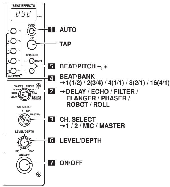
Beat effect section
15 BPM display
Displays the current track tempo as Beats Per Minute (BPM).
- The display flashes during BPM calculation and when BPM cannot be calculated.
16 BPM measuring mode button/indicator (AUTO)
Each time the button is pressed, the BPM measuring mode alternates as follows:
AUTO mode:
The AUTO button lights and the BPM is calculated automatically. This is the default mode whenever power is first turned on.
TAP mode (manual input):
The AUTO button does not light, and BPM is input manually by using the TAP button.
17 TAP button
The BPM is calculated from the intervals at which the TAP button is struck. If the TAP button is tapped in the AUTO mode, the mode automatically switches to the TAP mode (manual input).
18 Beat select buttons (BEAT/PITCH -, +)
- (Beat up): Doubles the calculated BPM.
- (Beat down): Halves the calculated BPM.
- If one of the BEAT/PITCH buttons (-, +) is pressed while holding the TAP button depressed, the BPM can be changed (40 to 999, in 1-step increments).
During in-loop sampler play, the loop play speed is changed. - (Beat up): Play speed becomes faster while button is pressed.
-(Beat down): Play speed becomes slower while button is pressed.
19 Beat select/bank buttons/indicators (BEAT 1 (1/2), 2 (3/4), 4 (1/1), 8 (2/1), 16 (4/1) / BANK)
Use to select the beat for synchronizing effects (P.11)
The selected button lights.
During in-loop sampler play, the buttons function as bank buttons to record samples of the music (P. 12).
- If the BEAT/BANK button is pressed while holding the ERASE (BEAT/PITCH-) button depressed, the music sample recorded in the BEAT/BANK button will be erased.
20 Effect selector (DELAY/ECHO/FILTER/FLANGER/PHASER/ROBOT/ROLL/IN-LOOP SAMPLER)
Use to select desired type of effect (P. 10 to 12).
21 Effect channel selector (CH. SELECT 1/2/MIC/MASTER)
Use to select the channel to which beat effects are applied (P. 11).
When [MIC] is selected, effects are applied to both microphone 1 and microphone 2.
22 Effect parameter dial (LEVEL/DEPTH)
Adjusts the quantitative parameters for selected beat effect (P. 11 to 12)
23 Effect button/indicator (ON/OFF)
Sets selected beat effects ON/OFF (P. 11).
When effects are disabled (OFF), the button lights. When effects are enabled (ON), the button flashes. Whenever power is first turned ON, effects default to OFF.
Microphone input control
24 Microphone 1 level control dial (MIC 1 LEVEL)
Use to adjust the volume of microphone 1. (Adjustable range -∞ to 0 dB)
When the connection panel's MIC/AUX switch is set to [AUX], this dial adjusts the sound volume for the left channel (AUX(L)).
25 Microphone 2 level control dial (MIC 2 LEVEL)
Use to adjust the volume of microphone 2. (Adjustable range -∞ to 0 dB)
When the connection panel's MIC/AUX switch is set to [AUX], this dial adjusts the sound volume for the right channel (AUX(R)).
26 Microphone equalizer control dial (EQ)
Use to adjust the tone of microphones 1 and 2. When rotated fully clockwise, attenuation of low-range sound is maximized. When rotated fully counterclockwise, attenuation of high-range sound is maximized. (Adjustable range 0 dB to -12 dB)
27 Microphone function selector switch (MIC)
OFF:
No microphone sound is output.
ON:
Microphone sound is output normally.
TALK OVER:
Microphone sound is output; when sound is input to a connected microphone, the TALK OVER function operates and all sound other than that from the microphone is attenuated by 20 dB.
Headphones output section
28 Headphone cue button/indicator (CH-1, CH-2, MASTER)
Press the button for the source you wish to monitor with headphones. When a button is OFF, its indicator lights dimly; when ON, the button indicator lights brightly (P. 8).
When the [ECHO] effect is selected, the effect is not applied to headache outputs if headache cue button CH-1 or CH-2 are set to ON.
29 Headphones level adjust dial (LEVEL)
Adjusts the output level of the headphones jack. (Adjustable range: -∞ to 0 dB).
30 Headphones jack (PHONES)
Located on the unit's front panel.
MIXER OPERATIONS
BASIC OPERATIONS
- Set rear panel POWER switch to ON.
-
Set the input selector switch for the desired channel to choose the connected component.
-
The function of the PHONO/LINE input connectors is set using the PHONO/LINE switch on the connection panel.
-
Use the TRIM dial to adjust the input level.
- Use the channel equalizer dials (HI, MID, LOW) to adjust the tone.
- Use the channel fader lever to adjust the sound volume of the selected channel.
-
To use the cross fader on the selected channel, set the cross fader selector switch to either the middle position (×) or the right position () , then operate the cross fader lever.
-
When not using the cross fader, set the cross fader selector switch to [THRU].
-
Use the MASTER LEVEL dial to adjust the overall sound volume.
[Selecting Stereo or Monaural]
When the connection panel's STEREO/MONO switch is set to [MONO], the master output becomes a monaural combination of L+R channels.
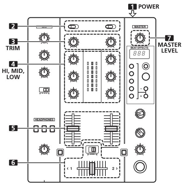
[Microphone Input]
- Set the connection panel's MIC/AUX switch to [MIC].
-
Set the MIC switch to [ON] or [TALK OVER].
-
When the switch is set to [TALK OVER], if sounds of over -15 dB are detected by the microphone, the output for all sound sources other than the microphone is attenuated by 20 dB.
-
Use the MIC 1 LEVEL dial to adjust the sound volume of MIC 1, and the MIC 2 LEVEL dial to adjust the sound volume of MIC 2.
- Use the microphone equalizer dial (EQ) to adjust the tone of the microphone sound.
- The microphone equalizer function operates simultaneously on microphones 1 and 2.
![PIONEER DJM-400 - [Microphone Input] - 1](/content/2025/01/118584/images/5f091ad931b599af10aa11cc67b9489e7d2f71814f88525a45de604bb83d70e7.jpg)
[Auxiliary Input]
- Set the connection panel's MIC/AUX switch to [AUX].
- The MIC1 input connector functions as AUX(L) input, and the MIC2 input connector functions as AUX(R) input.
- Set the MIC switch to [ON] or [TALK OVER].
- When the switch is set to [TALK OVER], if a sound is input to the AUX connectors, the output for all sources other than the AUX input is attenuated by 20 dB.
- Use the MIC 1 LEVEL dial to adjust the sound from the L channel, and MIC 2 LEVEL dial to adjust the sound from the R channel.
- Use the microphone equalizer dial (EQ) to adjust sound tone.
[Headphones Output]
- Use the headphones cue button (CH-1, CH-2, MASTER) to select the source to be output to the headphones.
The selected source button lights brightly.
[Relationship of headphones cue button and headphones output]
| Headphone cue button | Headphones Output | |||
| CH-1 | CH-2 | MASTER | L channel | R channel |
| ON | OFF | OFF | CH-1(L) | CH-1(R) |
| OFF | ON | OFF | CH-2(L) | CH-2(R) |
| OFF | OFF | ON | MASTER(L) | MASTER(R) |
| ON | ON | OFF | CH-1(L)+CH-2(L) | CH-1(R)+CH-2(R) |
| ON | OFF | ON | CH-1(MONO) | MASTER(MONO) |
| OFF | ON | ON | CH-2(MONO) | MASTER(MONO) |
| ON | ON | ON | CH-1(MONO)+CH-2(MONO) | MASTER(MONO) |
2. Use the LEVEL dial to adjust the headphones sound level.
[Selecting the Cross Fader Curve]
The sound volume response to fader lever operation can be set to one of two characteristic curves.
Use the cross fader selector switch to select the desired cross fader response curve.
- At the center position (×) , the curve operates to produce an even, neutral rise throughout the cross fader's movement.
- At the right position 广 , the curve operates to produce a rapid rise with the cross fader's movement (sound from [2 > ] is produced as soon as the lever leaves side [ 1] ).
- The curve settings operate the same on both sides [ 1] and [2 > ] .
FADER START FUNCTION
By connecting the optional Pioneer DJ CD Player control cable, the channel fader and cross fader can be used to start CD playback.
When the mixer's channel fader lever or cross fader lever are moved, the CD player is released from the pause mode and automatically -- and instantly -- begins playback of the selected track. Also, when the fader lever is returned to its original position, the CD player returns to its cue point (back cue), thus allowing "sampler" type play.
Cross fader start play and back cue play
When the CD player assigned to channel 1 is set to standby at a cue point, moving the cross fader lever from the right (2) side toward the left (1) side, automatically starts play on the channel 1 CD player.
When the cross fader lever reaches the left (1) side, the CD player assigned to channel 2 goes to back cue (returns to cue point). Also, when the CD player assigned to channel 2 is set to standby at a cue point, moving the cross fader lever from the left (1) side to the right (2) side, automatically starts playback on the channel 2 CD player. When the cross fader lever reaches the right (2) side, the channel 1 CD player goes to back cue (returns to cue point).
- The back cue is performed even if the input selector switch is not set to [CD].
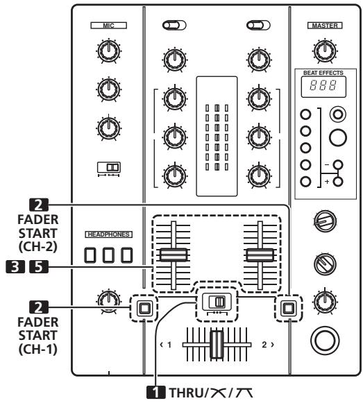
[Using the Channel Fader to Start Playback]
- Set the cross fader selector switch to the left (THRU) position.
- Press the FADER START button for the channel (1 to 2) connected to the CD player you wish to control.
- The button for the selected channel lights.
- Set the channel fader lever to its lowest position.
- Set the CD player to the desired cue point, and engage cue point standby.
- If a cue point has already been set, it is not necessary to set the CD player to standby at the cue point.
- At the instant you wish to start playback, move the channel fader lever.
- CD player begins playback.
- After playback has begun, if the channel fader lever is returned to its minimum position, the CD player returns to the cue point and reenters standby mode (back cue).
- If the cross fader selector switch is set to a position other than [THRU], the cross fader control is enabled and channel fader cannot be used for control.
[Using the Cross Fader to Start Playback]
![PIONEER DJM-400 - [Using the Cross Fader to Start Playback] - 1](/content/2025/01/118584/images/64cfd19a4dba4889ed1896e88827fe890cfabc9d244a05d0a3f818a76c481382.jpg)
- Set the cross fader selector switch to the middle (×) or the right () position.
-
Press the FADER START button for the channel (1 to 2) connected to the CD player you wish to control.
-
The button for the selected channel lights.
-
Set the cross fader lever fully to the opposite side from the channel you wish to start.
-
Set the CD player to the desired cue point, and engage cue point standby.
-
If a cue point has already been set, it is not necessary to set the CD player to standby at the cue point.
-
At the instant you wish to start playback, move the cross fader lever.
-
CD player begins playback.
-
After playback has begun, if the cross fader lever is moved fully to the side opposite from its start, the CD player assigned to the opposite side channel will return to the cue point and enter standby mode (back cue).
-
If the cross fader selector switch is set to [THRU], channel fader operation is enabled, and the cross fader cannot be used to control playback.
EFFECT FUNCTIONS
This unit is equipped with a total of 8 basic effects using beat effects and in-loops linked to the BPM. By changing the parameters for each effect, a wide variety of new effects can be produced. By using the BEAT/BANK buttons to set the time parameters, an even wider assortment of beat effects can be produced.
TYPES OF BEAT EFFECTS
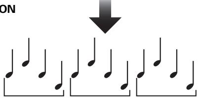
1. DELAY (One repeat sound)
This function allows a delay sound with beat of 1/2 , 3/4 , 1/1 , 2/1 or 4/1 to be added quickly and simply. For example, When a 1/2 beat delay sound is added, four beats become eight beats. Also, by adding a 3/4 beat delay sound, the rhythm becomes syncopated.
Original (4 beats)
1/2 delay (8 beats)

Example


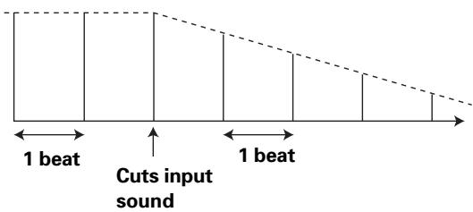
2. ECHO (Multiple repeat sounds)
This function allows an echo sound with beat of 1/2, 3/4, 1/1, 2/1 or 4/1 to be added quickly and simply.
For example, when a 1/1 beat echo sound is used to cutoff the input sound, a sound in synch with the beat is repeated together with fadeout.
Also, by adding a 1/1 beat echo to the microphone, the microphone sound repeats in synch with the music beat.
If a 1/1 beat echo is applied to the vocal portion of a track, the song takes on an effect reminiscent of a "round".
Example
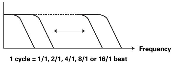
3. FILTER
In units of 1/1 , 2/1 , 4/1 , 8/1 or 16/1 beat, the filter frequency is moved, greatly changing the sound coloration.
Example
4. FLANGER
In units of 1/1, 2/1, 4/1, 8/1 or 16/1 beat, 1 cycle of flanger effect is produced quickly and easily.
Example
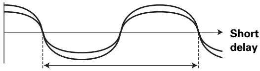
1 cycle = 1/1, 2/1, 4/1, 8/1 or 16/1 beat
5. PHASER
In units of 1/1, 2/1, 4/1, 8/1 or 16/1 beat, 1 cycle of phaser effect is produced quickly and easily.
Example
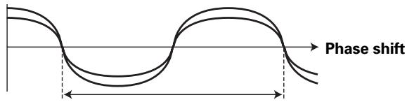
1 cycle = 1/1, 2/1, 4/1, 8/1 or 16/1 beat
6. ROBOT
Generates a sound effect resembling that produced by a robot.
7. ROLL
Sounds of 1/2, 3/4, 1/1, 2/1 or 4/1 beat are recorded and output repetitively.
Example

Effect ON
1/1 roll
Repeat
PRODUCING BEAT EFFECTS
Beat effects allow the instant setting of effect times in synch with the BPM (beats per minute), thus allowing the production of a wide variety of effects in synch with the current rhythm, even during live performances.
1. Press the AUTO button to set the Beats Per Minute (BPM = track tempo) measuring mode.
AUTO: The AUTO button lights, and the BPM of the input sound is measured automatically.
TAP: The BPM is input manually by tapping on the TAP button. The AUTO button indicator does not light.
- Whenever power is first turned ON, the function defaults to the [AUTO] mode.
- In the event the track's BPM cannot be detected automatically, the display's BPM counter will flash.
- The effective range in the AUTO mode is 70 to 180 BPM. It may not be possible to measure some tracks accurately.
In this case, use the TAP mode for manual BPM input.
[Using the TAP Button for Manual BPM Input] If the TAP button is tapped two times or more in synch with beat (1/4 notes), the BPM will be recorded as the average value recorded during that interval.
- When BPM mode is set to [AUTO], tapping the TAP button will cause the BPM mode to change to the TAP mode, and the interval at which the TAP button is pressed will be measured.
- When the BPM is set via the TAP button, the beat multiple becomes "1/1" or "4/1" (depending on the effect selected), and the time for 1 beat (1/4 notes) or 4 beats will be set as the effect time.
[Using the BEAT/PITCH buttons for Manual BPM Input] By pressing the BEAT/PITCH buttons (-, +) while holding the TAP button depressed, the BPM can be changed.
- The BPM can be set from 40 to 999 in 1-step increments.
2. Set the effect selector to an effect other than [IN-LOOP SAMPLER].
See P. 10 regarding the various effects.
3. Set the effect channel selector to the channel you wish to apply the effect to.
- If [MIC] is selected, the effect will be applied to both microphone 1 and microphone 2.
4. Press one of the BEAT/BANK buttons to select the beat to which you wish to synchronize the effect.
- Values can be selected from [1/2, 3/4, 1/1, 2/1, 4/1] or [1, 2, 4, 8, 16] . (The multiple differs depending on the effect. See page 10 for details.)
- The selected button will light.
- The effect time corresponding to the beat's multiple is set automatically.
Example: When BPM=120
1 / 1 = 500ms
1 / 2 = 250ms
2 / 1 = 1000ms
5. Use the BEAT/PITCH buttons (-, +) to select the beat multiple to which you wish to synchronize the effects.
- When [+] is selected, the beat calculated from the BPM is doubled, and when [-] is pressed, the beat calculated from the BPM is halved.
- When the time parameter lies within the range calculated from the BPM, the BEAT/BANK button corresponding to that value lights. When the parameter falls between two beat values, both BEAT/BANK buttons will flash. When the values is less than 1/2 (1), the 1/2(1) button will flash, and when greater than 4/1 (16), the 4/1(16) button will flash.
- During use of [DELAY], [ECHO], or [ROLL] effects, if the [-] , [+] buttons are used to shift the multiple, the "3/4" value will be skipped. However, the 3/4 multiple can be selected by pressing the 3/4 button directly.
6. Rotate the LEVEL/DEPTH dial to set the quantitative parameter for the selected effect.
See P. 12 for details regarding the effect of rotating the dial on the parameter.
7. Set the ON/OFF button to ON to enable the selected effect.
Each time the button is pressed, the effect is toggled ON/OFF. (Whenever power is first turned ON, the function defaults to OFF).
- The ON/OFF button flashes when effects are ON.
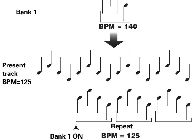
IN-LOOP SAMPLER
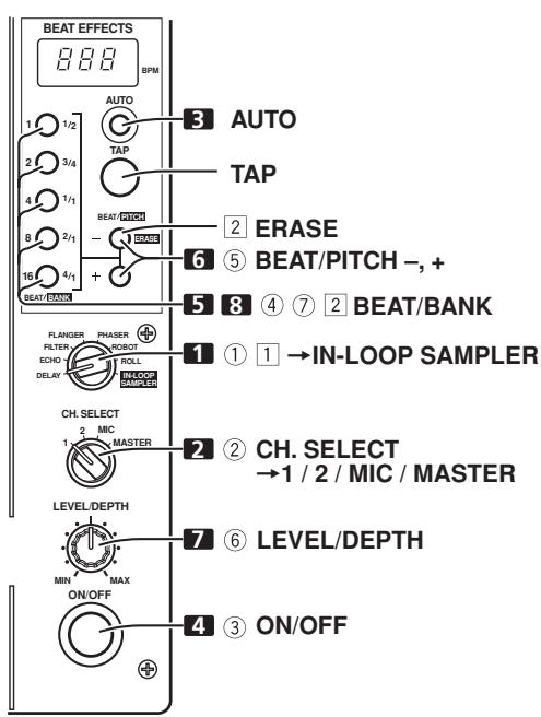
This function detects the current track's BPM, and 4 beat sources are recorded in up to five memory banks, and played as loops in sync with the current track's BPM. Overlapped recording is also possible.
1. Set the effect selector to [IN-LOOP SAMPLER].
2. Set the effect channel selector to the channel you wish to sample record.
3. Measure the BPM.
- Perform step 1 of the section "PRODUCING BEAT EFFECTS" (P. 11). 11
4. Set the ON/OFF button to ON.
-
At the point you wish to sample record, press one of the non-lighted BEAT/BANK buttons.
-
Lighted BEAT/BANK buttons have already been recorded, and cannot be used again unless their recorded contents are erased.
- Recording begins automatically when the sound signal from CD player or other component is detected. During recording, the BEAT/BANK button will flash quickly. During recording standby, the button will flash slowly at intervals.
-
When 4 beats of sound at the measured BPM have been recorded, the BEAT/BANK button flashes slowly and loop play is performed.
-
If the beat becomes unsynchronized, press one of the BEAT/PITCH buttons (-, +) to resynchronize the timing of the playback sample to the currently playing track.
-
The playback speed increases while the [+] button is depressed, and decreases while the [-] button is depressed.
-
Rotate the LEVEL/DEPTH dial to adjust the sound balance between source and sample.
- To stop loop playback, press the corresponding BEAT/BANK button.
- The BEAT/BANK button indicator will change from slow flashing to steadily lighted.
[To Playback a Recorded Sample]
① Set the effect selector switch to [IN-LOOP SAMPLER].
② Use the effect channel selector to choose the channel for loop playback.
③ Set the ON/OFF button to ON.
④ Press the BEAT/BANK button containing the sample you wish to play as a loop.
- The BEAT/BANK buttons with recorded samples are lighted.
- The selected button will flash slowly and loop play will begin.
⑤ If the beat becomes unsynchronized, press one of the BEAT/PITCH buttons (-, +) to resynchronize the timing of the playback sample to the currently playing track. - The playback speed increases while the [+] button is depressed, and decreases while the [-] button is depressed.
⑥ Rotate the LEVEL/DEPTH dial to adjust the sound balance between source and sample.
⑦ To stop loop playback, press the corresponding BEAT/BANK button.
- The BEAT/BANK button indicator will light steadily.
[Erasing a Recorded Sample]
1 Set the effect selector to [IN-LOOP SAMPLER].
2 While holding the ERASE (BEAT/PITCH -) button depressed, press the BEAT/BANK button containing the sample you wish to erase.
- The BEAT/BANK buttons containing recorded samples are lighted.
- The indicator in the selected BEAT/BANK button will go out and the sample will be erased.
8. IN-LOOP SAMPLER
This function allows you to store 4-beat sounds in up to 5 banks, then output them repeatedly.
Example
EFFECT PARAMETERS
| Name | BEAT/BANK button parameters | Parameter 1 (BEAT button) | Parameter 2 (LEVEL/DEPTH dial) | |
| Contents | Setting Range (unit) | |||
| 1 DELAY | Sets delay time of 1/2 to 4/1 per 1 beat of BPM time. | Sets delay time. | 1 to 8 000 (ms) | Sets balance between original and delay sound. |
| 2 ECHO | Sets delay time of 1/2 to 4/1 per 1 beat of BPM time. | Sets delay time. | 1 to 8 000 (ms) | Sets balance between original sound and echo sound. |
| 3 FILTER | Cycle of cutoff frequency shift is set in unit of 1/1 to 16/1 relative to 1 beat of BPM. | Sets cycle for cutoff time shift. | 10 to 32 000 (ms) | Amount of effect increases when dial is turned clockwise. |
| 4 FLANGER | Cycle of flanger shift is set in units of 1/1 to 16/1 relative to 1 beat of BPM. | Sets cycle for flanger effect shift. | 10 to 32 000 (ms) | Amount of effect increases when dial is turned clockwise. When dial is turned fully counterclockwise, only original sound is output. |
| 5 PHASER | Cycle of phaser effect shift is set in units of 1/1 to 16/1 relative to 1 beat of BPM. | Sets cycle for phase effect shift. | 10 to 32 000 (ms) | Amount of effect increases when dial is turned clockwise. When dial is turned fully counterclockwise, only original sound is output. |
| 6 ROBOT | Robot sound effects can be set in 7 fixed values from -100 % to +100 %. | Set robot sound effect. | -100, -66, -50, 0, +26, +50, +100 (%) (fixed values) | Amount of effect increases when dial is turned clockwise. |
| 7 ROLL | Sets effect time of 1/2 to 4/1 per 1 beat of BPM time. | Sets effect time. | 10 to 8 000 (ms) | Sets balance of original sound and ROLL sound. No change is produced when dial is turned toward the right side of the center position. |
| 8 IN-LOOP SAMPLER | Selects bank for recording/playback of 4 beat source. | — | — | Sets balance of original sound and recorded sample. No change is produced when dial is turned toward the right side of the center position. |
TROUBLESHOOTING
Incorrect operations are often mistaken for trouble and malfunctions. If you think there is something wrong with this component, check the points below. Sometimes the trouble may originate from another component. Thus, also check the other electrical appliances also in use.
If the trouble cannot be rectified even after checking the following items, contact your dealer or nearest PIONEER service center.
| Symptom | Possible Cause | Remedy |
| No power | • The power cord is not connected. | • Connect to power outlet. |
| No sound, or sound volume is too low. | • Input selector switch is set incorrectly. • PHONO/LINE input selector switch is set incorrectly. • Connection cables are connected incorrectly, or connections are loose. • Jacks or plugs are dirty. | • Set input selector to playback component. • Set the PHONO/LINE input selector to the component being played. • Connect correctly. • Clean soiled jacks/plugs before connecting. |
| Sound is distorted. | • Master output level is too high. • Input level is too high. | • Adjust master output level (MASTER LEVEL) dial. • Adjust the TRIM dial so that the input level approaches 0 dB on the channel level indicator. |
| Cross fader doesn’t work. | • Cross fader selector switch is set to [THRU]. | • Correctly set the switch to a setting other than [THRU]. |
| Can’t perform fader start with CD player. | • The FADER START button is set to OFF. • Rear panel CONTROL jack is not connected to CD player. • Only the rear panel CONTROL jack is connected to the CD player. | • Set the FADER START button to ON. • Use a control cable to connect the CONTROL jacks of DJM-400 and CD player. • Connect both the CONTROL jacks and CD input connectors. |
| Effects don’t work. | • Effect channel selector (CH. SELECT) setting is incorrect. • Effect parameter adjust dial (LEVEL/DEPTH) is set to [MIN]. | • Correctly select the channel on which you wish to apply effects. • Adjust the effect parameter adjust dial. |
| BPM can’t be measured. Measured BPM value is incorrect. | • Input level is set too high, or too low. • BPM may not be correctly measurable with some tracks. | • Adjust the TRIM dial. • Strike the TAP button to set BPM manually. |
| The measured BPM value is different from the value published with the CD. | • Some differences may occur due to differences in BPM detection methods. | • No remedy is necessary. |
Static electricity or other external interference may cause the unit to malfunction. To restore normal operation, turn the power off and then on again.
FONCTIONS DES EFFETS
Publication de Pioneer Corporation.
© 2006 Pioneer Corporation.
1. Interruptions Power
WAARSCHUWING NETSNOER
23 Effecttoets/indicator (ON/OFF)
[Kiezen van stereo of mono]
Copyright © 2006 Pioneer Corporation.
LOW. -12 dB (completely hacla derecha)
a 0 dB (centroid) (100 Hz)
Estamericana.
Laughter, a laughter, a laughter, a laughter, a laughter, a laughter, a laughter, a laughter, a laughter, a laughter, a laughter, a laughter, a laughter, a laughter, a laughter, a laughter, a laughter, a laughter, a laughter, a laughter, a laughter, a laughter, a laughter, a laughter, a laughter, a laughter, a leger, a leger, a leger, a leger, a leger, a leger, a leger, a leger, a leger, a leger, a leger, a leger, a leger, a leger, a leger, a leger, a leger, a leger, a leger, a leger, a leger, a leger, a leger, a leger, a leger, a legger, a legger, a legger, a legger, a legger, a legger, a legger, a legger, a legger, a legger, a legger, a legger, a legger, a legger, a legger, a legger, a legger, a legger, a legger, a legger, a legger, a legger, a legger, a legger, a legger, a lekker
Copyright © 2006 Pioneer Corporation.
Published by Pioneer Corporation.
Copyright © 2006 Pioneer Corporation.
All rights reserved.


- IMPORTANT
- CAUTION
- RISK OF ELECTRIC SHOCK DO NOT OPEN
- IMPORTANT: THE MOULDED PLUG
- OPERATING ENVIRONMENT
- WARNING
- VENTILATION CAUTION
- POWER-CORD CAUTION
- CAUTIONS REGARDING HANDLING
- LOCATION
- INSTALL THE UNIT IN A WELL-VENTILATED LOCATION WHERE IT WILL NOT BE EXPOSED TO HIGH TEMPERATURES OR HUMIDITY
- CLEANING THE UNIT
- CONTENTS
- BEFORE USING
- OPERATIONS
- OTHER
- SPECIFICATIONS
- 1.GENERAL
- AUDIO SECTION
- INPUT/OUTPUT CONNECTOR SYSTEMS
- ACCESSORIES
- FEATURES
- BEAT EFFECTS
- BEAT SELECT BUTTONS
- IN-LOOP SAMPLER
- ④ 2 MIC INPUT, AUX SWITCHING
- ⑤ AUTO TALK-OVER
- OTHER FUNCTIONS
- CONNECTIONS
- CONNECTION PANEL
- POWER SWITCH
- STEREO/MONO SELECTOR SWITCH
- MIC2/AUX(R) INPUT CONNECTOR
- MIC/AUX INPUT SELECTOR SWITCH
- MIC1/AUX(L) INPUT CONNECTOR
- SIGNAL GROUNDING TERMINAL (SIGNAL GND)
- CHANNEL 1 CONTROL CONNECTOR
- CHANNEL 1 CD INPUT CONNECTORS (CD)
- CHANNEL 1 PHONO/LINE INPUT CONNECTORS
- CHANNEL 1 PHONO/LINE SELECTOR SWITCH
- CHANNEL 2 CONTROL CONNECTOR
- CHANNEL 2 CD INPUT CONNECTORS (CD)
- CHANNEL 2 PHONO/LINE INPUT CONNECTORS
- CHANNEL 2 PHONO/LINE SELECTOR SWITCH
- MASTER OUT 2 OUTPUT CONNECTORS
- MASTER OUT 1 OUTPUT CONNECTORS
- POWER INLET (AC IN)
- HEADPHONES JACK (PHONES)
- CONNECTING INPUTS
- PIONEER DJ CD PLAYERS
- ANALOG TURNTABLE
- CONNECTING OTHER DEVICES WITH LINE LEVEL OUTPUT
- MICROPHONE
- AUXILIARY INPUT CONNECTORS
- CONNECTING OUTPUTS
- MASTER OUTPUT
- HEADPHONES
- CONNECT THE POWER CORD LAST
- NAMES AND FUNCTIONS OF PARTS
- 1 CHANNEL 1 INPUT SELECTOR SWITCH
- 2 CHANNEL 2 INPUT SELECTOR SWITCH
- 3 TRIM ADJUST DIAL
- 4 CHANNEL EQUALIZER HIGH-RANGE ADJUST DIAL (HI)
- 5 CHANNEL EQUALIZER MID-RANGE ADJUST DIAL (MID)
- 6 CHANNEL EQUALIZER LOW-RANGE ADJUST DIAL (LOW)
- 7 CHANNEL LEVEL INDICATORS
- 8 CHANNEL FADER LEVERS
- 9 CHANNEL 1 FADER START BUTTON/INDICATOR (FADER START)
- 10 CHANNEL 2 FADER START BUTTON/ INDICATOR (FADER START)
- 11 CROSS FADER SELECTOR SWITCH
- 12 CROSS FADER LEVER
- 13 MASTER LEVEL INDICATORS (MASTER LEVEL)
- 14 MASTER OUTPUT LEVEL DIAL (MASTER LEVEL)
- BEAT EFFECT SECTION
- 15 BPM DISPLAY
- 16 BPM MEASURING MODE BUTTON/INDICATOR (AUTO)
- 17 TAP BUTTON
- 18 BEAT SELECT BUTTONS (BEAT/PITCH -, +)
- 19 BEAT SELECT/BANK BUTTONS/INDICATORS (BEAT 1 (1/2), 2 (3/4), 4 (1/1), 8 (2/1), 16 (4/1) / BANK)
- 20 EFFECT SELECTOR (DELAY/ECHO/FILTER/FLANGER/PHASER/ROBOT/ROLL/IN-LOOP SAMPLER)
- 21 EFFECT CHANNEL SELECTOR (CH. SELECT 1/2/MIC/MASTER)
- 22 EFFECT PARAMETER DIAL (LEVEL/DEPTH)
- 23 EFFECT BUTTON/INDICATOR (ON/OFF)
- MICROPHONE INPUT CONTROL
- 24 MICROPHONE 1 LEVEL CONTROL DIAL (MIC 1 LEVEL)
- 25 MICROPHONE 2 LEVEL CONTROL DIAL (MIC 2 LEVEL)
- 26 MICROPHONE EQUALIZER CONTROL DIAL (EQ)
- 27 MICROPHONE FUNCTION SELECTOR SWITCH (MIC)
- HEADPHONES OUTPUT SECTION
- 28 HEADPHONE CUE BUTTON/INDICATOR (CH-1, CH-2, MASTER)
- 29 HEADPHONES LEVEL ADJUST DIAL (LEVEL)
- 30 HEADPHONES JACK (PHONES)
- MIXER OPERATIONS
- BASIC OPERATIONS
- [SELECTING STEREO OR MONAURAL]
- [MICROPHONE INPUT]
- [AUXILIARY INPUT]
- [HEADPHONES OUTPUT]
- USE THE LEVEL DIAL TO ADJUST THE HEADPHONES SOUND LEVEL
- [SELECTING THE CROSS FADER CURVE]
- FADER START FUNCTION
- CROSS FADER START PLAY AND BACK CUE PLAY
- [USING THE CROSS FADER TO START PLAYBACK]
- EFFECT FUNCTIONS
- TYPES OF BEAT EFFECTS
- DELAY (ONE REPEAT SOUND)
- ECHO (MULTIPLE REPEAT SOUNDS)
- FILTER
- FLANGER
- PHASER
- ROBOT
- ROLL
- PRODUCING BEAT EFFECTS
- PRESS THE AUTO BUTTON TO SET THE BEATS PER MINUTE (BPM = TRACK TEMPO) MEASURING MODE
- [USING THE TAP BUTTON FOR MANUAL BPM INPUT] IF THE TAP BUTTON IS TAPPED TWO TIMES OR MORE IN SYNCH WITH BEAT (1/4 NOTES), THE BPM WILL BE RECORDED AS THE AVERAGE VALUE RECORDED DURING THAT INTERVAL
- [USING THE BEAT/PITCH BUTTONS FOR MANUAL BPM INPUT] BY PRESSING THE BEAT/PITCH BUTTONS (-, +) WHILE HOLDING THE TAP BUTTON DEPRESSED, THE BPM CAN BE CHANGED
- SET THE EFFECT SELECTOR TO AN EFFECT OTHER THAN [IN-LOOP SAMPLER]
- SET THE EFFECT CHANNEL SELECTOR TO THE CHANNEL YOU WISH TO APPLY THE EFFECT TO
- PRESS ONE OF THE BEAT/BANK BUTTONS TO SELECT THE BEAT TO WHICH YOU WISH TO SYNCHRONIZE THE EFFECT
- USE THE BEAT/PITCH BUTTONS (-, +) TO SELECT THE BEAT MULTIPLE TO WHICH YOU WISH TO SYNCHRONIZE THE EFFECTS
- ROTATE THE LEVEL/DEPTH DIAL TO SET THE QUANTITATIVE PARAMETER FOR THE SELECTED EFFECT
- SET THE ON/OFF BUTTON TO ON TO ENABLE THE SELECTED EFFECT
- SET THE EFFECT SELECTOR TO [IN-LOOP SAMPLER]
- SET THE EFFECT CHANNEL SELECTOR TO THE CHANNEL YOU WISH TO SAMPLE RECORD
- MEASURE THE BPM
- SET THE ON/OFF BUTTON TO ON
- [TO PLAYBACK A RECORDED SAMPLE]
- [ERASING A RECORDED SAMPLE]
- TROUBLESHOOTING
- FONCTIONS DES EFFETS
- INTERRUPTIONS POWER
- WAARSCHUWING NETSNOER
- 23 EFFECTTOETS/INDICATOR (ON/OFF)
- [KIEZEN VAN STEREO OF MONO]
Brand : PIONEER
Model : DJM-400
Category : Mixer