
DJM-1000 - Mixer PIONEER - Free user manual and instructions
Find the device manual for free DJM-1000 PIONEER in PDF.
| Brand | Pioneer |
| Model | DJM-1000 |
| Product type | Professional DJ mixer |
| Dimensions (W × D × H) | 482 × 363.5 × 187.5 mm |
| Weight | 12.1 kg |
| Power supply | Mains 220-240 V, 50/60 Hz |
| Power consumption | 62 W |
| Operating temperature | +5 to +35 °C |
| Operating humidity | 5 to 85% (without condensation) |
| Number of channels | 6 |
| Channel equalizer | 3-band (HI, MID, LOW): -26 to +6 dB |
| Main isolator | 3-band (HI, MID, LOW): -∞ to +6 dB |
| Adjustable fader curve | 17 steps for channel fader and crossfader |
| A/D and D/A converter | 24 bits / 96 kHz |
| Special functions | Send/Return 2 systems, digital link, fader start, Talk Over |
| Cleaning | Soft dry cloth, diluted neutral detergent, no solvents |
| Safety | Do not expose to water, do not obstruct ventilation, disconnect if not in use |
| Spare parts | Available through Pioneer authorized after-sales service |
Frequently Asked Questions - DJM-1000 PIONEER
User questions about DJM-1000 PIONEER
0 question about this device. Answer the ones you know or ask your own.
Ask a new question about this device
Download the instructions for your Mixer in PDF format for free! Find your manual DJM-1000 - PIONEER and take your electronic device back in hand. On this page are published all the documents necessary for the use of your device. DJM-1000 by PIONEER.
USER MANUAL DJM-1000 PIONEER
Operating Instructions
Mode d'emploi
Bedienungsanleitung
Thank you for buying this Pioneer product.
Please read through these operating instructions so you will know how to operate your model properly. After you have finished reading the instructions, put them away in a safe place for future reference.
In some countries or regions, the shape of the power plug and power outlet may sometimes differ from that shown in the explanatory drawings. However the method of connecting and operating the unit is the same. K015 En
IMPORTANT

The lightning flash with arrowhead symbol, within an equilateral triangle, is intended to alert the user to the presence of uninsulated "dangerous voltage" within the product's enclosure that may be of sufficient magnitude to constitute a risk of electric shock to persons.
CAUTION
RISK OF ELECTRIC SHOCK
DO NOT OPEN
CAUTION:
TO PREVENT THE RISK OF ELECTRIC
SHOCK,DO NOT REMOVE COVER (OR
BACK).NO USER-SERVICEABLE PARTS
INSIDE. REFER SERVICING TO QUALIFIED SERVICE PERSONNEL.

The exclamation point within an equilateral
triangle is intended to alert the user to the
presence of important operating and
maintenance (servicing) instructions in the literature accompanying the appliance.
D3-4-2-1-1.En-A
Replacement and mounting of an AC plug on the power supply cord of this unit should be performed only by qualified service personnel.
IMPORTANT
FOR USE IN THE UNITED
KINGDOM
The wires in this mains lead are coloured in
accordance with the following code:
Blue : Neutral
Brown :Live
If the plug provided is unsuitable for your socket
outlets, the plug must be cut off and a suitable plug fitted.
The cut-off plug should be disposed of and must not be inserted into any 13 amp socket as this can result in electric shock. The plug or adaptor or the distribution panel should be provided with 3 A fuse. As the colours of the wires in the mains lead of this appliance may not correspond with coloured markings identifying the terminals in your plug, proceed as follows;
The wire which is coloured blue must be connected
to the terminal which is marked with the letter N or
coloured black.
The wire which is coloured brown must be
connected to the terminal which is marked with the
letter L or coloured red.
Do not connect either wire to the earth terminal of a
three pin plug.
NOTE
After replacing or changing a fuse, the fuse cover in
the plug must be replaced with a fuse cover which
corresponds to the colour of the insert in the base
of the plug or the word that is embossed on the
base of the plug, and the appliance must not be used without a fuse cover. If lost replacement fuse
covers can be obtained from your dealer.
Only 3 A fuses approved by B.S.L or A STA to
B.S.1362 should be used.
D3-4-2-1-2-2_En
WARNING
This equipment is not waterproof. To prevent a fire
or shock hazard, do not place any container filed
with liquid near this equipment (such as a vase or
flower pot) or expose it to dripping, splashing, rain
or moisture.
D3-4-2-1-3_A_En
WARNING
Before plugging in for the first time, read the following section carefully.
The voltage of the available power supply differs according to country or region. Be sure that the
power supply voltage of the area where this unit
will be used meets the required voltage (e.g., 230V
or 120V) written on the rear panel. D3-4-2-1-4_A_En
WARNING
To prevent a fire hazard, do not place any naked
flame sources (such as a lighted candle) on the
equipment.
D3-4-2-1-7a A En
VENTILATION CAUTION
When installing this unit, make sure to leave space
around the unit for ventilation to improve heat
radiation (at least 5 cm at rear, and 3 cm at each side).
WARNING
Slots and openings in the cabinet are provided for
ventilation to ensure reliable operation of the
product, and to protect it from overheating. To
prevent fire hazard, the openings should never
blocked or covered with items (such as newspapers,
table-cloths,curtains)or by operating the
equipment on thick carpet or a bed. D3-4-2-1-7b_A_En
Operating Environment
Operating environment temperature and humidity:
+5°C - +35°C (+41°F - +95°F); less than 85%RH
(cooling vents not blocked)
Do not install this unit in a poorly ventilated area, or in
locations exposed to high humidity or direct sunlight (or
strong artificial light)
D3-4-2-1-7c_A_En
This product complies with the Low Voltage Directive
(73/23/EEC, amended by 93/68/EEC), EMC Directives
(89/336/EEC, amended by 92/31/EEC and
93/68/EEC).
D3-4-2-1-9a_En
If the AC plug of this unit does not match the AC
outlet you want to use, the plug must be removed
and appropriate one fitted. Replacement and
mounting of an AC plug on the power supply cord of
this unit should be performed only by qualified
service personnel. If connected to an AC outlet, the
cut-off plug can cause severe electrical shock . Make
sure it is properly disposed of after removal.
The equipment should be disconnected by removing
the mains plug from the wall socket when left
unused for a long period of time (for example, when
D3-4-2-2-1a_A_En
CAUTION
The POWER switch on this unit will not completely
shut off all power from the AC outlet. Since the
power cord serves as the main disconnect device for
the unit, you will need to unplug it from the AC outlet
to shut down all power. Therefore, make sure the
unit has been installed so that the power cord can
be easily unplugged from the AC outlet in case of an
accident. To avoid fire hazard, the power cord should
also be unplugged from the AC outlet when left
unused for a long period of time (for example, when
on vacation).
D3-4-2-2-2a_A_En
POWER-CORD CAUTION
Handle the power cord by the plug. Do not pull out the
plug by tugging the cord and never touch the power
cord when your hands are wet as this could cause a
short circuit or electric shock. Do not place the unit, a
piece of furniture, etc., on the power cord, or pinch the
cord. Never make a knot in the cord or tie it with other
cords. The power cords should be routed such that they
are not likely to be stepped on. A damaged power cord
can cause a fire or give you an electrical shock. Check
the power cord once in a while. When you find it
damaged, ask your nearest PIONEER authorized
service center or your dealer for a replacement. S002_En
FEATURES
① High sound quality design
Analog signals are transmitted via the shortest path and converted to digital signals by a 96 kHz sampling, 24 bit, high-quality A/D converter, thus passing the signals to the digital mixing stage under optimum conditions.
Through the use of a 32 bit DSP, mixing is achieved with zero sound quality degradation, and together with simultaneous ideal filtering, optimum sound is produced for professional DJs working in clubs.
To get the most from these features, a great deal of care has been paid to perfecting the sound quality, including a high-rigidity chassis to cut down unnecessary vibrations that might affect the sound, together with a high-performance power section using an
R-core transformer that supports bass quality, thus creating clear and powerful sound ideal for club performances.
② 3 band isolator
Built-in 3-band isolator capable of producing level control +6 dB to - on each bandwidth.
The sharp operation feel allows the realization of a wide variety of DJ performances.
(3) 2-system, 3-type SEND/RETURN
A 2-system, 3-type SEND/RETURN (PRE INSERT/POST INSERT/AUX) is provided to allow multiple connection variations with other external devices, such as effectors and samplers, thus widening the range of DJ play potential.
Fader curve adjust
The fader curve adjust allows adjustment not only the cross fader curve (as on former models), but also of channel fader curve.
Both faders' functions can be adjusted within 17 steps, so that DJs can customize the settings to their own preferred settings.
⑤ Digital IN/OUT
Using digital input connectors provided for each of the sampling rates (44.1/48/96 kHz), a system can be built in which no sound quality degradation occurs when connecting to external digital devices.
A DIGITAL OUT connector with 24 bit/96 kHz sampling rate is provided, facilitating recording at studios and other situations demanding high sound quality.
Supports only linear PCM.
⑥ MIDI OUT
MIDI signals can be output to allow MIDI control of external devices.
⑦ Digital link function
Multiple functions can be performed by using digital link cables to connect other PIONEER DJ CD players, DJ effectors and AV mixers.
Other features
- By using a control cable to connect the unit to a PIONEER DJ-use CD player, playback can be started on the CD player in automatic linkage to operation of the fader ("fader start play").
- Built-in "3-band equalizer" enabling level control within range +6 dB to -26 dB at each bandwidth.
- Features "2-band booth EQ" for control of booth monitor response, thus facilitating booth monitoring by the DJ.
- Built-in "cross fader assign" function, enabling more flexible assigning of each channel's input to the cross fader.
- Built-in "TALK OVER function" automatically lowers track volume during MIC-input.
CONTENTS
FEATURES 3
CONFIRM ACCESSORIES 3
CAUTIONS REGARDING HANDLING 4
BEFORE USING
CONNECTIONS 5
CONNECTION PANEL 5
POWER CORD CONNECTION 6
CONNECTING TO THE INPUT CONNECTORS ... 6
CONNECTING TO THE EFFECTOR AND
OUTPUT CONNECTORS 7
MIDI CONNECTORS 7
CONNECTING MICROPHONES,HEADPHONES...8
DIGITAL LINK CONNECTIONS 8
PART NAMES AND FUNCTIONS 9
OPERATIONS
OPERATIONS 13
BASIC OPERATIONS 13
FADER CURVE ADJUSTMENTS 13
FADER START FUNCTION 14
USING EXTERNAL EFFECTORS 14
DIGITALLINKFUNCTION 15
OTHER
TROUBLESHOOTING 16
SPECIFICATIONS 17
BLOCK DIAGRAM 100
CONFIRM ACCESSORIES
Operating Instructions 1
Power cord 1
CAUTIONS REGARDING HANDLING
Location
Install the unit in a well-ventilated location where it will not be exposed to high temperatures or humidity.
- Do not install the unit in a location which is exposed to direct rays of the sun, or near stoves or radiators. Excessive heat can adversely affect the cabinet and internal components. Installation of the unit in a damp or dusty environment may also result in a malfunction or accident. (Avoid installation near cookers etc., where the unit may be exposed to oily smoke, steam or heat.)
- When the unit is used inside a carrying case or DJ booth, separate it from the walls or other equipment to improve heat radiation.
Installing the DJM-1000 in an EIA rack
The screw holes on the front panel of the DJM-1000 are designed for use in attaching the unit to a 19-inch EIA rack.
- Attach the unit to the rack using screws of the appropriate size (screws not provided with the unit).
- When installing the unit in a rack, take care to avoid pinching your fingers.
Note
- Never place this unit directly above a power amplifier, as the heat given off by the amplifier might result in damage to the unit. Placing the unit directly above a power amplifier might also result in ham radio signals being picked up or in other types of interference.
- Allow at least 1U (43.7 mm) space between this component and the one mounted above it, so as to assure that the cords connected to this unit's input/output connectors and terminals do not touch the component above.
- Always be sure to remove the unit from its rack before shipping.
- When moving the unit while still installed in its rack, exercise caution to avoid subjecting the unit to shocks or vibration.
Condensation
When this unit is brought into a warm room from previously cold surroundings or when the room temperature rises sharply, condensation may form inside, and the unit may not be able to attain its full performance. In cases like this, allow the unit to stand for about an hour or raise the room temperature gradually.
Cleaning the Unit
- Use a polishing cloth to wipe off dust and dirt.
- When the surfaces are very dirty, wipe with a soft cloth dipped in some neutral cleanser diluted five or six times with water and wrung out well, then wipe again with a dry cloth. Do not use furniture wax or cleaners.
- Never use thinners, benzene, insecticide sprays or other chemicals on or near this unit, since these will corrode the surfaces.
CONNECTIONS
CONNECTION PANEL
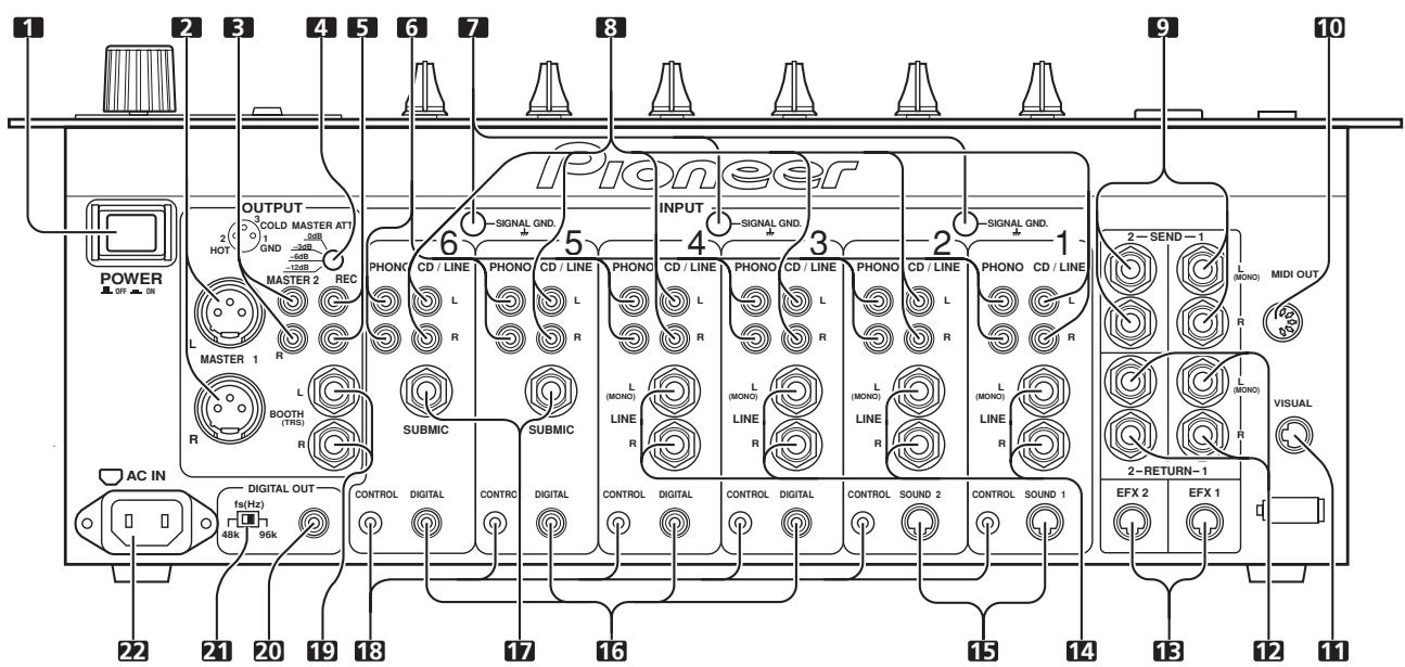
1. POWER switch
2. MASTER output connector 1 (MASTER 1)
XLR type balanced output (male connector).
3. MASTER output connector 2 (MASTER 2)
RCA type unbalanced output.
4. MASTER output attenuator dial (MASTER ATT.)
Attenuates the output level of MASTER 1 and MASTER 2 output. The level of attenuation can be chosen from 0 dB, -3 dB, -6 dB, -12 dB.
5. Recording output connectors (REC)
RCA type output connector for recording.
6. PHONO input connectors
RCA type phono level (for MM cartridge) input connectors.
Do not use for input of line level signals.
7. Signal grounding terminal (SIGNAL GND)
Use to connect grounding wire from analog player.
Not a terminal for safety grounding.
8. CD/LINE input connectors
RCA type line level input connectors.
Use to connect DJ CD players and/or line level output devices.
9. SEND output connectors (SEND 1, 2)
6.3 mm phone type output connectors.
Use to connects input connectors from external effectors, etc.
When only the L channel is connected, a monaural signal of L + R is output.
10. MIDI output connector (MIDI OUT)
DIN type output connector.
Connects with other MIDI devices (P.7).
11. VISUAL link connector
When a digital link cable is used to connect the unit to a PIONEER video mixer (switcher) supporting digital-linkage, the video mixer's cross fader can be controlled using the cross fader of the DJM-1000.
12. RETURN connectors (RETURN 1, 2)
6.3 mm phone type output connectors.
Connect to input connectors of external effectors, etc.
When only the L channel is connected, the input in the L channel will be input into the R channel.
13. EFX link input/output connectors (EFX 1, 2)
When a digital-link cable is used to connect the unit to a PIONEER DJ effector supporting digital linkage (EFX-1000), SEND/RETURN connections are performed at once digitally, and functions such as fader effect are also enabled.
14. LINE input connectors
6.3 ~mm phone type line level connectors.
When only the L channel is connected, the input to the L channel will also be input into the R channel.
15. CDJ link input connectors (SOUND 1, 2)
When a digital-link cable is used to connect the unit to a PIONEER DJ CD player supporting digital linkage, the digital audio connections and control cable connections are performed at once, and functions such as BPM synchro are also enabled.
16. DIGITAL input connectors
RCA type digital coaxial input connectors.
Connect to digital coaxial output connectors of DJ CD player, etc.
17. SUBMIC input connectors
6.3 mm phone type microphone input connectors.
Utilizes the DJM-1000's channels 5 and 6 as microphone input channels.
18. CONTROL connectors
03.5 mm mini phone-type input connector for connecting control cable to DJ CD player.
Allows use of the DJM-1000's fader function to control start/stop of a connected DJ CD player.
19. BOOTH monitor output connectors
6.3 ~mm phone type output connectors for booth monitor.
Changes the volume with the BOOTH MONITOR dial (LEVEL), unaffected to the MASTER fader (since output is TRS, both balanced and unbalanced outputs are supported).
20. Digital output connector (DIGITAL OUT)
RCA type digital coaxial output connector.
Digital master output.
21. Sampling frequency selector switch (48k/96k)
Chooses the sampling frequency of the digital output (96 kHz or 48 kHz).
22. Power inlet connector (AC IN)
Connect to AC outlet plug with the provided power cord.
Before making or changing connections, switch off the power and disconnect the power cord from the AC outlet.
POWER CORD CONNECTION
Connect the power cord last.
- When all other connections are completed, connect the supplied power cord to the AC inlet located on the rear panel of this unit, and connect the power plug to an AC outlet or auxiliary power socket on an amplifier.
- Be sure to use only the supplied power cord.
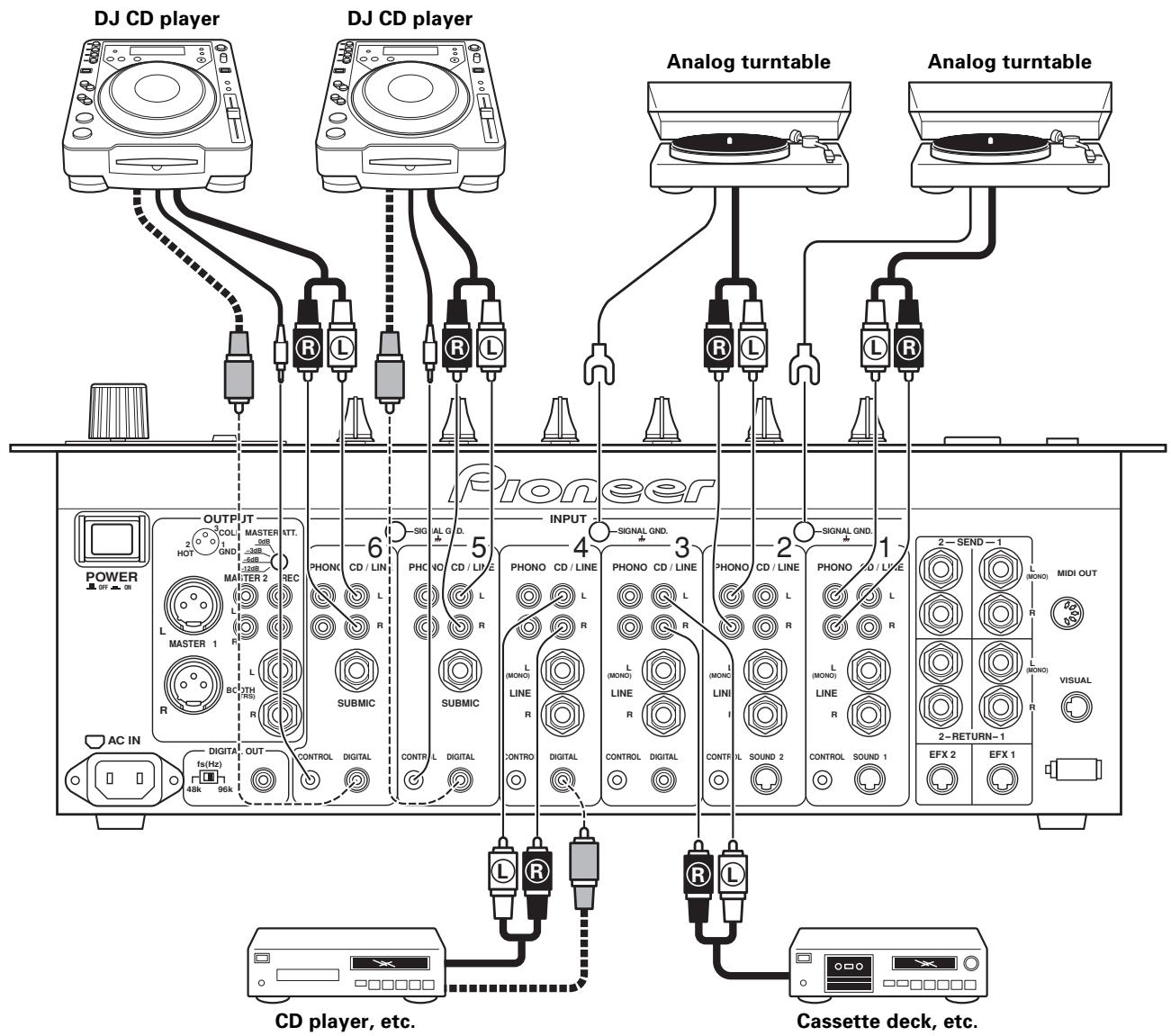
CONNECTING TO THE INPUT CONNECTORS
PIONEER DJ CD players
Connect the DJ CD player's audio output connectors to one of the sets of CD/LINE input connectors on the DJM-1000, and connect the control cable to the corresponding channel's CONTROL connector. Switch the input selector switch of the connected channel to [CD/LINE].
When using digital connections, connect the digital coaxial output connector to one of the DIGITAL input connectors of the DJM-1000, and switch the input selector switch of the connected channel to [DIGITAL] (no digital input connectors are provided for channel 1 and channel 2).
Analog turntables
Connect the audio output cables of the analog turntable to one set of PHONO input connectors on the DJM-1000, and switch the input selector switch of the connected channel to [PHONO]. The PHONO input of the DJM-1000 supports MM cartridges.
The ground cable of an analog turntable is connected to one of the SIGNAL GND terminals.
Other line level output devices
When connecting cassette decks or CD players, connect the audio output connectors to one of the CD/LINE input connectors of the DJM-1000, and switch the input selector switch of the connected channel to [CD/LINE].
When the connection plug is a 06.3 ~mm phone plug, connect to one of the LINE input connectors of the DJM-1000, and switch the input selector switch of the connected channel to [LINE] (no LINE input connectors are provided for channel 5 and channel 6). When only the L channel is connected, the input in the L channel will be input to the R channel as well.
Digital output devices
When using digital connections to devices such as CD players, connect the device's digital coaxial output connector to one of the DIGITAL input connectors of the DJM-1000, and switch the input selector switch of the connected channel to [DIGITAL] (no DIGITAL input connectors are provided for channel 1 and channel 2).
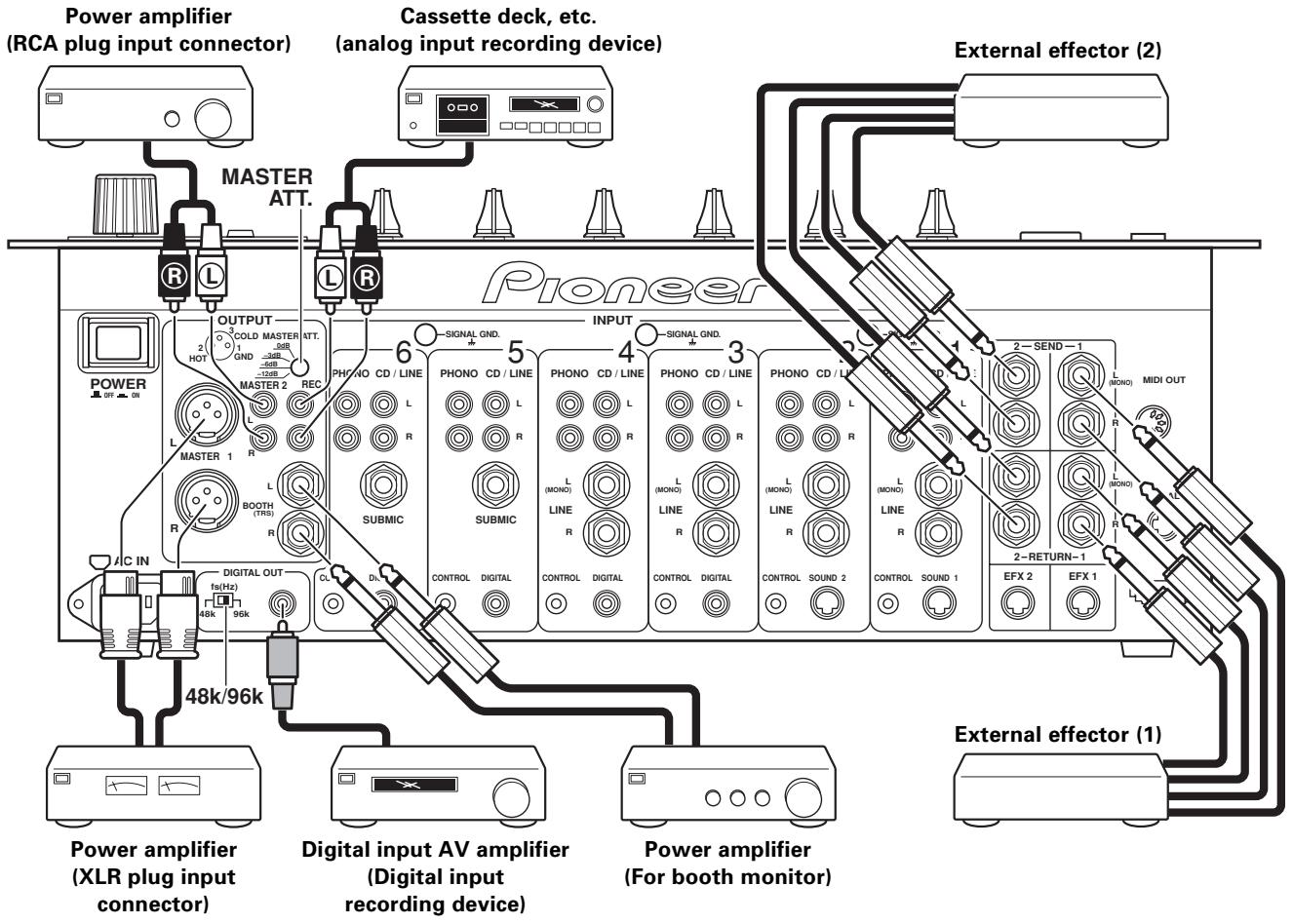
CONNECTING TO THE EFFECTOR AND OUTPUT CONNECTORS
Master output
There is an XLR plug correspondent balanced output MASTER 1, and a RCA plug correspondent unbalanced output MASTER 2. Set the output level using the MASTER ATT. dial to match the input sensitivity of the connected power amplifier.
Booth monitor output
Unbalanced output supporting 6.3 mm phone plug. Volume can be adjusted with the BOOTH MONITOR dial (LEVEL), regardless of the setting of the MASTER fader.
Recording output
Output connectors for recording, supports RCA plug.
Digital output
Coaxial digital output connector, supports RCA plug. Sampling frequency can be selected (96 kHz/48 kHz) in accordance with connected device.
External effector
Use a cable with 6.3 mm phone plugs to connect the DJ mixer's SEND connectors to the input connectors of an external effector. When using a monaural input effector, connect only the L channel output. In this way, the mixed L/R audio signal will be sent to the effector.
In the same way, use a cable with 6.3mm phone plugs to connect the DJ mixer's RETURN connectors to the output connectors of the external effector.
When the effector has only monaural output, connect the L channel input only. In this way, the signal from the effector will be input to both L/R channels.
MIDI CONNECTORS
MIDI (Musical Instrument Digital Interface) is a unified standard for transmitting data between electrical musical instruments and computers.
Data can be transmitted between devices with MIDI connectors using a MIDI cable.
The DJM-1000 can send operating data to external MIDI devices using the MIDI protocol.
| DJM-1000 control | MIDI control code | MIDI control name | MIDI Channel |
| Cross fader operation | CC11 | Expression | 1 |
- 0-127 MIDI data is output by operating the cross fader.
- When using the visual link function, MIDI data is not output.
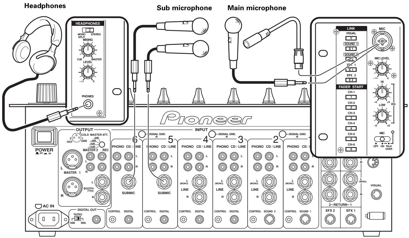
Headphones with 6.3 mm stereo phone plugs can be connected to the PHONES plug in the operation panel (top panel).
Main microphone
A microphone with either a 06.3mm phone plug or XLR plug can be connected to the MIC plug in the operation panel (top panel).
Sub microphone
A 06.3 mm phone plug microphone can be connected to the SUBMIC input connectors on channel 5 and channel 6 of the DJM-1000.
Switch the input selector switch of the connected channel to [SUBMIC].
DIGITAL LINK CONNECTIONS
(Includes connections to future components supporting digital link.)
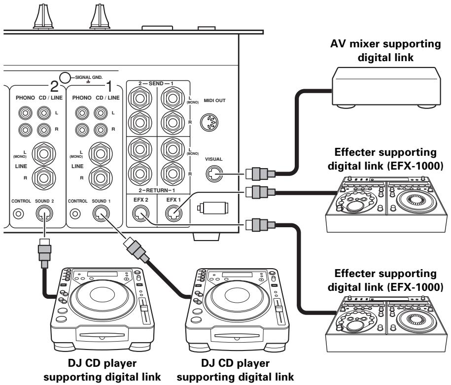
By connecting a single dedicated cable (digital link cable), exchange of audio signals and control signals can be performed digitally (The connection of audio cables or control cables is unneeded).
VISUAL link connector
When a digital link cable is used to connect the unit to a PIONEER video mixer (switcher) supporting digital linkage, the cross fader function of the video mixer can be operated by using the cross fader of the DJM-1000. (P.15)
EFX link input/output connectors (EFX 1, 2)
When a digital link cable is used to connect the unit to a PIONEER DJ effector supporting digital linkage (EFX-1000), SEND/RETURN connections are performed at once digitally, thus allowing the use of fader effect functions and BPM sync functions when sound link connections are used. (P.15)
CDJ link input connectors (SOUND 1, 2)
When a digital link cable is used to connect the unit to a PIONEER DJ CD player supporting digital linkage, digital audio connections and control cable functions are performed at once, and functions such as BPM synchro are also enabled. Switch the input selector switch of the channel 1 and 2 to [SOUND 1] and [SOUND 2]. (P.15)
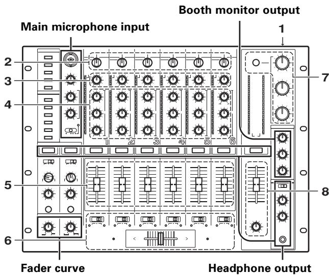
PART NAMES AND FUNCTIONS
Operation Panel
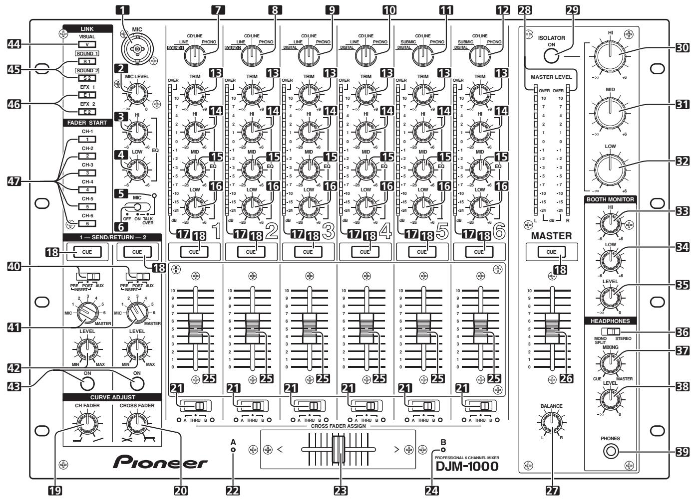
Main microphone input control section
1. Main MIC input connector
Connect to microphones with XLR type or phone type connector.
2. MIC LEVEL adjustment dial
Adjusts the volume of the main microphone.
(Adjustable range: - to 0 dB)
3. Microphone equalizer high-range sound adjust dial (EQ HI)
Adjusts the high-range sound of the main microphone.
(Adjustable range: -6 dB to +6 dB)
4. Mic equalizer low-range sound adjust dial (EQ LOW)
Adjusts the low-range sound of the main microphone.
(Adjustable range: -6 dB to +6 dB)
5. Microphone function indicator
Lights when MIC selector switch is set to [ON]. Flashes when selector switch is set to [TALK OVER].
6. MIC function selector switch
OFF:
Main microphone audio is not output.
ON:
Main microphone audio is output.
TALK OVER:
Main microphone audio is output. When a sound higher than -15 dB is input to the main microphone input, the TALK OVER function operates and the output of all sound except for the main microphone audio is attenuated 20~dB .
Channel input control section
7. Channel 1 input selector switch
SOUND 1:
Dedicated input for DJ CD players supporting digital link (mini DIN connector).
LINE:
Phone type connector (When a monaural signal is connected to only the L channel, the signal is input to both L and R channels).
CD/LINE:
RCA type connector with line level input.
PHONO:
RCA type connector with phono level input.
8. Channel 2 input selector switch
SOUND 2:
Dedicated input for DJ CD players supporting digital link (mini DIN connector).
LINE:
Phone type connector (when a monaural signal is connected to only the L channel, the signal is input to both L and R channels).
CD/LINE:
RCA type connector with line level input.
PHONO:
RCA type connector with phono level input.
9. Channel 3 input selector switch DIGITAL:
RCA type connector with coaxial cable digital input.
LINE:
Phone type connector (when a monaural signal is connected to only the L channel, the signal is input to both L and R channels).
CD/LINE:
RCA type connector with line level input.
PHONO:
RCA type connector with phono level input.
10. Channel 4 input selector switch
DIGITAL:
RCA type connector for coaxial cable digital input.
LINE:
Phone type connector (when a monaural signal is connected to only the L channel, the signal is input to both L and R channels).
CD/LINE:
RCA type connector with line level input.
PHONO:
RCA type connector with phono level input.
11. Channel 5 input selector switch
DIGITAL:
RCA type connector for coaxial cable digital input.
SUBMIC:
Phone type connector for sub microphone input (monaural).
CD/LINE:
RCA type connector with line level input.
PHONO:
RCA type connector with phono level input.
12. Channel 6 input selector switch
DIGITAL:
RCA type connector for coaxial cable digital input.
SUBMIC:
Phone type connector for sub microphone input (monaural).
CD/LINE:
RCA type connector with line level input.
PHONO:
RCA type connector with phono level input.
13. Channel 1-6 TRIM adjustment dials
Adjusts each channel's input level.
(Adjustable range: - to +9 dB, approaches 0 dB at midpoint)
14. Channel equalizer high-range sound adjust dials (EQ HI)
Adjusts each channel's high-range sound.
(Adjustable range: -26 dB to +6 dB)
15. Channel equalizer mid-range sound adjust dials (EQ MID)
Adjusts each channel's mid-range sound.
(Adjustable range: -26 dB to +6 dB)
16. Channel equalizer low-range sound adjust dials (EQ LOW)
Adjusts each channel's low-range sound.
(Adjustable range: -26 dB to +6 dB)
17. Channel level indicators
Displays each channel level. The display provides 2 seconds peak hold.
18. Headphone CUE button/indicators
The selected source to be monitored by headphones is chosen by pressing the CUE button for RETURN 1, RETURN 2, channel 1-6, or MASTER. When multiple buttons are pressed at once, the selected audio sounds are mixed. When a button is pressed again, the selection is canceled. The buttons of unselected sources light dimly, and the buttons of the selected sources light brightly.
Fader control section
19. Curve adjust channel fader dial (CURVE ADJUST CH FADER)
Adjusts the curve characteristics of the channel fader. (P.13)
20. Curve adjust cross fader dial (CURVE ADJUST CROSS FADER)
Adjusts the curve characteristics of the cross fader. (P.13)
21. CROSS FADER ASSIGN switches/indicators
Selects which side of the cross fader the output from each channel is directed to. (When multiple channels have been selected in the same side, the combined sum is assigned to that side.)
A:
The channel output is directed to the A side (left side) of the cross fader. The A indicator will light.
THRU:
The channel output is directed to the master output without going through the cross fader. Both A and B indicators will go out.
B:
The channel output is directed to the B side (right side) of the cross fader. The B indicator will light.
22. Cross fader assign A indicator (A)
Lights orange when power is ON.
23. Cross fader slider
The audio directed to either the A side or B side by the CROSS FADER ASSIGN switch for each channel is output in accordance with the cross fader curve set by the CURVE ADJUST dial (CROSS FADER).
24. Cross fader assign B indicator (B)
Lights green when power is ON.
25. Channel fader slider
Adjusts volume of each channel.
(Adjustable range: - to 0 dB)
Outputs according to the channel fader curve set by the CURVE ADJUST dial (CH FADER).
Master output control section
26. MASTER fader slider
Adjusts the volume of the master output.
(Adjustable range: - to 0 dB)
The master output is the combination of the channel whose audio has been set to [THRU] by the CROSS FADER ASSIGN switch, together with the audio passed through the cross fader and the audio from the main microphone (depending on the mode, RETURN input will also be added).
27. MASTER BALANCE dial
Adjusts the L/R channel balance of the master output, booth monitor output, recording output, and digital output.
28. MASTER LEVEL indicators (L, R)
Displays output levels of the L channel and the R channel. Each segment provides 2 seconds of peak hold.
29. MASTER ISOLATOR button/indicator (ON)
Turns master isolator function ON/OFF.
The isolator function operates with respect to master output 1, master output 2, booth monitor output, recording output and digital output.
Turns off when OFF, and lights when ON.
30. MASTER ISOLATOR high-range sound adjust dial (HI)
Use to adjust the high-range sound of the master output signal.
(Adjustable range: - to +6 dB)
31. MASTER ISOLATOR mid-range sound adjust dial (MID)
Used to adjust the mid-range sound of the master output signal.
(Adjustable range: - to +6 dB)
32. MASTER ISOLATOR low-range sound adjust dial (LOW)
Used to adjust the low-range sound of the master output signal.
(Adjustable range: - to +6 dB)
Booth monitor control section
33. BOOTH MONITOR equalizer high-range sound adjust dial (HI)
Used to adjust the high-range sound of the booth monitor output signal.
(Adjustable range: -6 dB to +6 dB)
34. BOOTH MONITOR equalizer low-range sound adjust dial (LOW)
Used to adjust the low-range sound of the booth monitor output signal.
(Adjustable range: -6dB to +6 dB)
35. BOOTH MONITOR LEVEL adjust dial
Adjusts the volume of the booth monitor output.
Adjustable regardless of setting of master fader.
(Adjustable range: - to 0 dB)
Headphone output section
36. Headphone output selector switch (HEADPHONES — MONO SPLIT/STEREO)
MONOSPLIT:
The audio source selected by the headphone CUE button is output from the left channel, and the master audio is output from the right channel (Only when MASTER is selected with the headphone CUE button).
STEREO:
The selected audio is output in stereo.
37. Headphone MIXING dial (HEADPHONES MIXING)
When turned clockwise (MASTER direction) the master output audio is output (only when MASTER is selected with the headphones CUE button); when turned counterclockwise (CUE direction), the audio output will be a mixture of the sound from the channel selected with the headphones CUE button, and the sound coming from the external effector (RETURN).
38. Headphone LEVEL adjust dial (HEADPHONES LEVEL)
Adjusts the output volume of the headphone connector. (Adjustable range: - to 0 dB)
39. Headphone jack (PHONES)
SEND/RETURN section
40. SEND/RETURN type selector switches
Use to switch between the sending stage (SEND) and input stage (RETURN) for signals when connected to an external effector (P.14).
[Pre-Insert type]
[Post-Insert type]
[AUX type]
41. SEND channel selector switches
Use to select the send audio from MIC, channels 1-6, and MASTER.
42. RETURN input level adjust dials (LEVEL)
Adjusts the level of the signal returned.
(Adjustable range: - to +6 dB)
43. SEND/RETURN buttons/indicators (ON)
Use to switch ON/OFF the SEND/RETURN operation of the selected type on the selected channel.
Lights when a plug is inserted to the RETURN connector, or when a component supporting digital link is connected to the EFX connector. If the button is pressed when lighted, the function turns ON and the indicator flashes. When indicator is ON, input signal to RETURN connector is enabled. When a digital-link component is connected to the EFX connector, the digital link component (digital signal) is given priority.
Link function ON/OFF section
44. VISUAL LINK button/Indicator (V)
When a digital link cable (mini DIN connector) is used to connect a PIONEER video mixer/switcher supporting digital link, the video mixer's cross fader can be operated using the cross fader of the DJM-1000.
The indicator lights when the function is turned ON.
45. SOUND LINK buttons 1, 2 (SOUND 1, 2)/indicator(S1,2)
When this unit is connected via digital link to a PIONEER DJ effector with digital link support (EFX-1000), and a PIONEER DJ CD player with digital link support is also connected via digital link cable (mini DIN connector), setting these buttons to ON enables BPM sync functions.
The indicator lights when the function is turned ON.
46. Effector LINK buttons 1, 2 (EFX 1, 2)/Indicator (E 1, 2)
When a digital link cable (mini DIN connector) is used to connect this unit to a PIONEER DJ effector with digital link support (EFX-1000), setting these buttons to ON enables fader effect functions.
The indicator lights when the function is turned ON.
Fader start/stop ON/OFF section
47. Fader start button/indicators (FADER START CH-1 to CH-6)
When the CROSS FADER ASSIGN switches for each channel are used to select [A] or [B], the cross fader start/stop function of that channel's DJ CD player are turned ON/OFF.
When [THRU] is selected by the CROSS FADER ASSIGN switch for each channel, the channel fader start/stop function for that channel's DJ CD player is turned ON/OFF. The button for each channel lights up when the fader start/stop function is turned ON, and is turned off when the fader start/stop function is turned OFF.
OPERATIONS
BASIC OPERATIONS
- Set the POWER switch located on the rear panel (connection panel) to ON.
- Set the input selector switches for the channels used to the devices connected to those channels.
- Use the TRIM dial to adjust the input level.
- Adjust the tone using the EQ dials (HI, MID, LOW).
- Adjust the volume of the channel with the channel fader slider.
-
When cross fading between channels, use the CROSS FADER ASSIGN switch to choose between channel [A] and channel [B] of the cross fader, and operate the cross fader.
-
When not using the cross fader, choose [THRU] with the CROSS FADER ASSIGN switches.
-
When using the isolator, switch the MASTER ISOLATOR button ON, and adjust the level of each bandwidth with the MASTER ISOLATOR dials (HI, MID, LOW).
-
The MASTER ISOLATOR button will light when switched ON.
-
Use the MASTER fader slider to adjust the overall volume, and adjust the left and right volume balance by using the MASTER BALANCE dial.
[Main microphone input]
- When using the main microphone, either set the MIC selector switch to [ON] or set to [TALK OVER].
- When set to [TALK OVER], the output of all sound except for the main microphone audio is attenuated 20 dB when a sound higher than -15 dB is input to the main microphone input.
- Adjust the volume with the MIC LEVEL dial, and adjust the tone with the MIC EQ dials (HI, LOW).
[Booth monitor output]
- Adjust the volume with the BOOTH MONITOR dial (LEVEL).
- The volume can be adjusted with the BOOTH MONITOR dial (LEVEL), regardless of the setting of the MASTER fader slider.
- Adjust the tone using the BOOTH MONITOR dial (HI "high-range sound") and BOOTH MONITOR dial (LOW "low-range sound").
[Headphones output]
- Choose the source with the headphone CUE button (channel 1-6, MASTER, RETURN 1, RETURN 2).
-
The chosen headphone CUE button will light brightly.
-
Use the HEADPHONES selector switch (MONO SPLIT/STEREO) to select the format of the audio output.
-
When [MONO SPLIT] is chosen, the audio chosen with the CUE button will be output from the left channel, and the master audio (enabled only when the CUE button for the MASTER is turned ON) will be output from the right channel.
-
When [STEREO] is chosen, the audio chosen with the CUE button will be output in stereo.
-
When [MONO SPRIT] is chosen, use the HEADPHONES dial (MIXING) to adjust the balance of the left channel (chosen by the headphone CUE button), and the right channel (master audio—supported only when the headphone CUE button for MASTER is turned ON).
-
When turned clockwise (MASTER direction) the master output (only when CUE button for MASTER is turned ON) will be output, and when turned counterclockwise (CUE direction) the audio chosen by the CUE button will be output.
-
Adjust the volume of the headphones with the HEADPHONES dial (LEVEL).
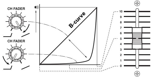
FADER CURVE ADJUSTMENTS
This allows adjustment of the sound volume change characteristics corresponding to the movement of the fader operation.
Turn the CURVE ADJUST dial (CH FADER), and adjust the curve characteristics of the channel fader.
- When turned fully to the right, raising the fader will cause the volume to change in a nearly linear fashion (equivalent to B-curve).
- When turned fully to the left, the volume curve will change so that sound volume increases slowly until the fader is raised almost fully.
- The curve of the channels 1-6 will all change at the same time.
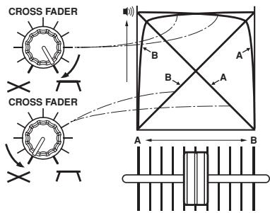
Turn the CURVE ADJUST dial (CROSS FADER), and adjust the curve characteristics of the cross fader.
- When turned all the way to the right, the cross fader becomes a steep rising curve in which moving the fader from the side causes instant appearance of the sound on the opposite side.
- When turned all the way to the left, the cross fader becomes an almost linier volume change curve.
- Both curves of the A and B side will change at once.
FADER START FUNCTION
By using a control cable to connect the unit to an optional PIONEER CD player, playback on the CD player can be started using the channel fader or cross fader functions (if a digital link connection is made, use of the control cable is unnecessary).
The CD player's pause function is canceled when the mixer's channel fader slider or cross fader slider is moved, and the playback of the track starts automatically and instantly. In addition, by returning the fader to it's former position, the CD player's playback can be returned back to the cue point (back cue), so that sampler-like playback can be performed.
[Cross fader start play & back cue play]
During cue point standby on the CD player assigned to channel A of the cross fader, moving the cross fader slider from the right side (B side) to the left side (A side) causes the CD player connected to channel A to start playback.
When the cross fader slider reaches the left side (A side), the CD player assigned to channel B will back cue (return to cue point). When the CD player assigned to channel B is in cue point standby mode, moving the cross fader slider from the left side (A side) to the right side (B side), causes playback on the CD player assigned to channel B to begin. When the cross fader slider reaches the right side (B side), the CD player assigned to channel A will back cue.
- Back cue will occur even if the input selector switch is not set to [CD/LINE].
![PIONEER DJM-1000 - [Cross fader start play & back cue play] - 1](/content/2019/11/118581/images/0ad8aaa42dc02fce338f2ab2b5bdd4e939f5ec0f3c0751398de96c31f3f3245c.jpg)
[Starting playback with channel fader]
① Press the FADER START button for the channel (CH-1 to CH-6) connected to the CD player you wish to control.
- The button of the selected channel will light.
② Move the channel fader slider to the [0] position.
③ Set a cue point in the CD player, and set to standby at cue point.
- If a cue point has already been set, the CD player does not have to be set to standby at the cue point.
④ Move channel fader slider at the desired timing to start playback.
- CD player will start playback.
- After playback has started, moving the channel fader slider back to [0] causes the CD player to return to cue point and enter standby mode (back cue).
* Channel fader is enabled for control only when CROSS FADER ASSIGN switch is set to [THRU].
[Starting playback with cross fader]
Press the FADER START button for the channel (CH-1 to CH-6) connected to the CD player you wish to control.
- The button of the selected channel will light.
2 Set the CROSS FADER ASSIGN switch of the selected channel to either [A] or [B].
- When assigning to channel A (left side) of the cross fader, set to [A].
- When assigning to channel B (right side) of the cross fader, set to [B].
3 Move the cross fader slider as far as it will go to the opposite side of the channel you wish to start.
4 Set a cue point on the CD player, and set to standby at the cue point.
- If a cue point has already been set, the CD player does not have to be set to standby at the cue point.
Move the cross fader slider at the desired timing to start playback.
- CD player will start playback.
-
After playback has started, by moving the cross fader slider all the way, the CD player assigned at the opposite side will return to cue point and enter standby mode (back cue).
-
The fader start function may not operate properly when digital connections are made alone. In this event, connect the CD player's analog connectors as well.
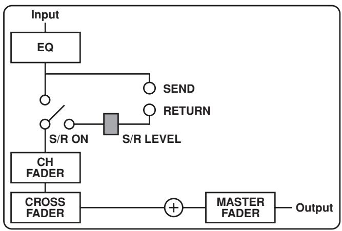
USING EXTERNAL EFFECTORS
Two effectors can be connected if desired.
- Use the SEND channel selector switch to choose the source to be sent to the effector.
- Select from either [MIC], channel [1]-[6], or [MASTER].
- Use the SEND/RETURN selector switch to choose the stage to which the effector is connected.
- When the send channel is set to [MIC], [INSERT] and [AUX] switching only are enabled from the same point for both [PRE] and [POST]. When send channel is set to [MASTER], only [INSERT] is enabled.
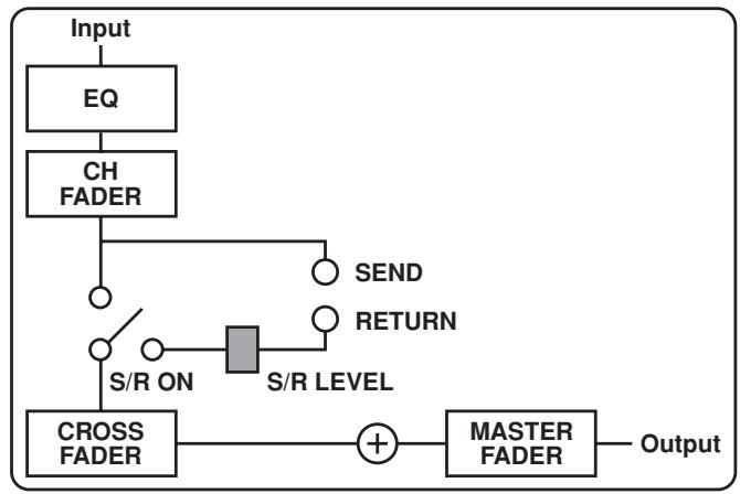
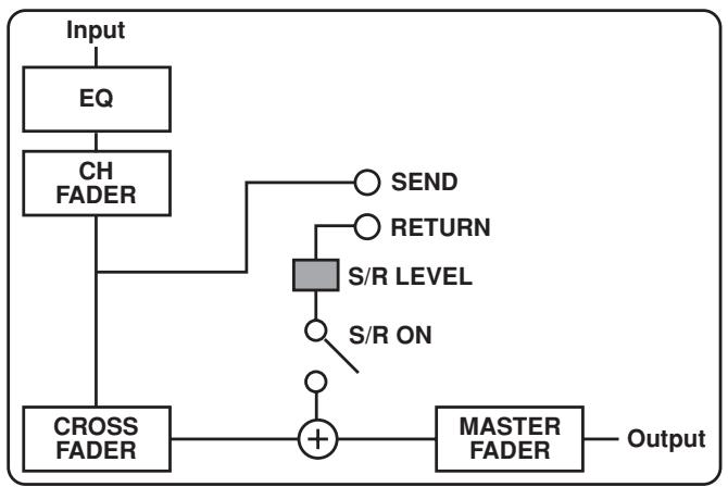
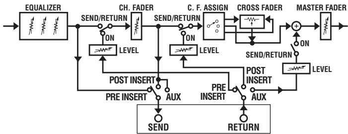
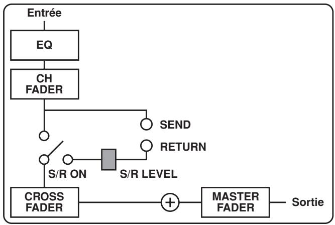
PRE INSERT:
Equalizer output, sent from before the channel fader and returned to same point.
POST INSERT:
Channel fader output, sent from before the cross fader assign, and returned to the same point.
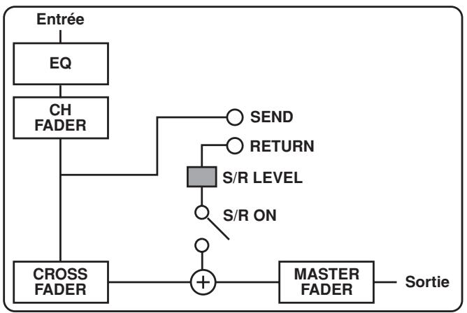
AUX:
Channel fader output, sent from before the cross fader assign and returned to the point before the master fader, and then added to any other output. The original sound which has been sent will also be passed through the cross fader assign and added.
- Set the SEND/RETURN button to ON.
- The SEND/RETURN button flashes.
- Adjust the RETURN volume with the RETURN dial (LEVEL).
| Position Source | PRE POST AUX INSERT | PRE POST AUX INSERT | PRE POST AUX INSERT |
| MIC | INSERT | AUX | |
| CH-1 — CH-6 | PRE | POST | AUX |
| MASTER | INSERT | ||
DIGITAL LINK FUNCTION
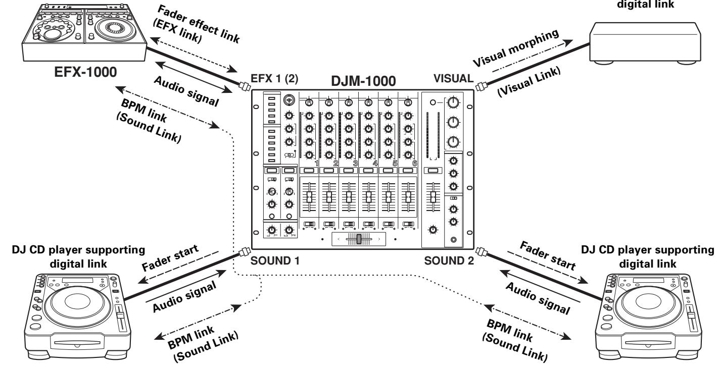
Link system diagram
DJ effector supporting digital link
Digital link connections for EFX-1000
Use a digital link cable to connect a PIONEER DJ effector (EFX-1000) to the EFX 1 or 2 connectors of this unit.
This link provides a high-fidelity digital connection and enables use of the EFX-1000's effects functions.
Operations following connection are the same as those when "USING EXTERNAL EFFECTORS" (P.14). If the SEND/RETURN connectors (phone plug cable) are connected simultaneously, the EFX link input/output connection (via the digital link cable) is automatically given priority.
For more information regarding settings, consult the EFX-1000 Operating Instructions.
Fader effect link (EFX Link)
When the connections described above have been made, moving the channel fader slider produces the same effects as when operating the EFX-1000's jog dial.
- Set EFX-1000's digital jog break to ON.
- Use the SEND channel selector switches to select the channel to be used for fader effects (channel [1]-[6] can be selected).
- Set the effector LINK buttons (EFX 1, 2) to ON.
- The effector LINK buttons will light.
Note: The sound volume for the channel selected will become the same as that set with the maximum channel fader; as a result, make your selection after confirming the level of sound produced when the channel fader is set to maximum. - Turn the SEND/RETURN button ON.
- The SEND/RETURN button will flash.
- Operate the fader for the selected channel.
- The EFX-1000's digital job break meter and sound will change in response to the position of the channel fader.
- When the SEND channel selector switch setting is changed, the fader effect link is canceled, and the effector LINK button indicator goes out.
Digital link connections for the digital link DJ CD player
A digital link cable can be used to connect a digital link DJ CD player to the SOUND 1, 2 connectors of this unit.
This link provides a high-fidelity digital connection for mixing of sounds from the DJ CD player.
The fader start function is also enabled by means of this single digital link.
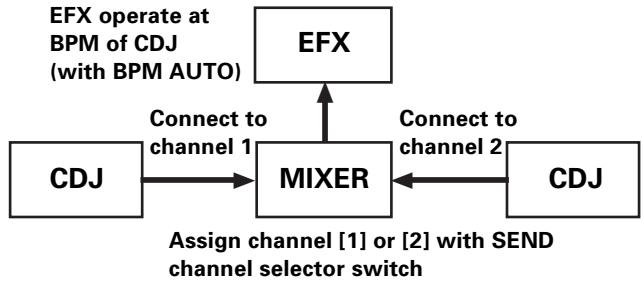
BPM link (Sound Link)
When a digital link cable is used to connect a supported DJ CD player to the SOUND 1, 2 connectors, and the DJ effector EFX-1000 is connected via digital link cable to the EFX 1 or 2 connectors, the effects can be added at the more accurate BPM value measured with the DJ CD player.
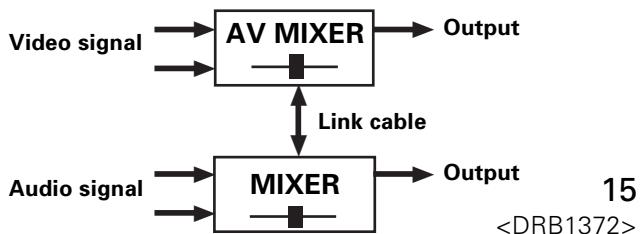
Visual morphing (Visual Link)
When a digital link cable is used to connect the DJ mixer's VISUAL connector to an AV mixer supporting digital link (and with the link function enabled), the AV mixer's cross fader can be moved automatically in linkage with the cross fader of the DJ mixer, thus allowing both audio and video to be modified together.
TROUBLESHOOTING
Incorrect operations are often mistaken for trouble and malfunctions. If you think there is something wrong with this component, check the points below. Sometimes the trouble may originate from another component. Thus, also check the other electrical appliances also in use.
If the trouble cannot be rectified even after checking the following items, contact your dealer or nearest PIONEER service center.
| Symptom | Possible Cause | Countermeasure |
| Power does not turn on. | ·The power cord has not been connected. | ·Connect the cord to a power outlet. |
| Little or no sound. | ·Input selector switch is in the wrong position. ·Connection cable hasn't been connected properly or has been disconnected. ·Connector or plug is dirty. ·MASTER ATT. dial on rear panel is set too low ([-12 dB], etc.). | ·Choose the device currently playing with the input selector switch. ·Connect properly. ·Clean and reconnect. ·Adjust the setting of the MASTER ATT. dial in the rear panel. |
| Sound is distorted. | ·Master output level is too high. ·Input level is too high. | ·Adjust the MASTER ATT. dial in the rear panel. ·Adjust the TRIM dial so that the input level approaches 0 dB on the CHANNEL LEVEL indicators. |
| Cannot cross fade. | ·The setting of the CROSS FADER ASSIGN switch ([A], [THRU], [B]) is incorrect. | ·Set the CROSS FADER ASSIGN switch of the channel desired to cross fade properly. |
| Cannot fader start the CD player. | ·The fader start switch is set to OFF. ·The rear panel's player CONTROL connector hasn't been connected. | ·Set the fader start switch to ON. ·Use the control cable to connect the unit and CD player. |
| External effector's sound is distorted. | ·The input level from the external effector is too high. | ·Lower the external effector's output level, or adjust the return level using the RETURN dial (LEVEL). |
| External effector doesn't operate. | ·The SEND/RETURN button is turned OFF. ·The effector is not connected to the RETURN connector or EFX connector located in the rear panel. ·The SEND channel selector switch setting is mistaken. | ·Turn the SEND/RETURN button ON. ·Connect the effector to either the SEND/RETURN connector or the EFX 1 or EFX 2 connectors in the rear panel. ·Select the source to which you want to apply effects with the SEND channel selector switch. |
| Link function doesn't work. | ·A device supporting digital link is not connected to the digital link connectors (EFX 1, EFX 2, SOUND 1, SOUND 2, VISUAL) in the rear panel. | ·Use a digital link cable to connect the DJM-1000 to a supported device. |
Static electricity or other external interference may cause the unit to malfunction. To restore normal operation, turn the power off and then on again.
Check the following items if the link connection is not established properly:
| CAUTION Indicators | Meaning | Countermeasure |
| Each link indicator flashes twice. | Unsupported components are connected at the link input/output connectors. | Check the connections at the link input/output connectors. |
| Each link indicator flashes three times. | The link connectors of a single DJM-1000 are connected together, or the link connectors from two DJM-1000s are connected together. | Check connections. |
| Each link indicator flashes four times. | Communication error occurred at the link input/output connectors. | Check connections and connector cables. |
SPECIFICATIONS
1. General Specifications
Power supply voltage.. AC 220-240 V, 50/60 Hz
Power consumption 62 W
Operating temperature +5^ to +35^
Operating humidity 5% to 85% (no condensation)
Weight 12.1 kg
External dimensions 482 (W) x 363.5 (D) x 187.5 (H) mm
2. Audio Section
Sampling rate. 96 kHz
A/D, D/A converter 24 bits
Frequency response 20 Hz to 20 kHz
S/N ratio (at full scale)
LINE 104 dB
PHONO 88 dB
MIC 84 dB
Distortion (LINE-MASTER1) 0.005 %
Headroom 19 dB
Input level
PHONO -52 dBu (47 kΩ)
MIC, SUBMIC. -52 dBu (3 kΩ)
CD/LINE, LINE -12 dBu (22 kΩ)
RETURN -12 dBu (22 kΩ)
Output level
MASTER1 +2 dBu (600 Ω)
MASTER2 +2 dBu (10 kΩ)
REC -8 dBu (10 kΩ)
BOOTH +2 dBu (600 Ω)
SEND -12 dBu (10 kΩ)
PHONES +8.5 dBu (32 Ω)
Crosstalk (LINE) 88 dB
Channels 6
Channel equalizer
HI -26 dB to +6 dB (13 kHz)
MID -26 dB to +6 dB (1 kHz)
LOW. -26 dB to +6 dB (70 Hz)
Microphone equalizer
HI -6 dB to +6 dB (10 kHz)
LOW. -6 dB to +6 dB (100 Hz)
Booth monitor equalizer
HI -6 dB to +6 dB (10 kHz)
LOW. -6 dB to +6 dB (100 Hz)
3. Input output connectors
PHONO input connectors RCA pin jack 6
CD/LINE, LINE input connectors
RCA pin jack 6
Phone jack (6.3 mm) 4
MIC, SUBMIC input connectors
XLR connector/Phone jack (Ø6.3 mm) 1
Phone jack (Ø6.3 mm) 2
DIGITAL coaxial input connectors RCA pin jack 4
RETURN input connectors Phone jack (06.3 mm) 2
MASTER output connectors XLR connector 1 RCA pin jack 1
BOOTH output connectors RCA pin jack 1
REC output connectors RCA pin jack 1
SEND output connectors Phone jack (06.3 mm) 2
DIGITAL coaxial output connector
RCA pin jack 1
Digital link connectors (EFX 1, 2, SOUND 1, 2, VISUAL)
Mini DIN
MIDI OUT connector 5PDIN 1
4. Accessories
Operating instructions 1
Power cord 1
Appearance and specifications are subject to change without notice.
Microphone principal
[Type de post-insertion]
[Type AUX]
44. Bouton/voyant VISUAL LINK (V)
1. Interruptions Power
(HEADPHONES — MONO SPLIT/STEREO)
MONOSPLIT:
WAARSCHUWING NETSNOER
⑤ Entrada/salida digital (IN/OUT)
Laitters are the main components of a CD. The CD is usually composed of two parts: the first part, which is usually used to prepare the CD for use in the home, and the second part, which is usually used to record the CD. The first part is usually used to record the CD in the home, while the second part is usually used to record the CD in the office.
27. Mando de balance principal (MASTER BALANCE)
Conector de salute coaxial DIGITAL
Published by Pioneer Corporation.
Copyright © 2004 Pioneer Corporation.
All rights reserved.
PIONEER CORPORATION 4-1, Meguro 1-Chome, Meguro-ku, Tokyo 153-8654, Japan
PIONEER EUROPE NV MULTIMEDIA DIVISION Pioneer House Hollybush Hill, Stoke Poges, Slough SL2 4QP U.K. TEL: +44-1-753-789-789
PIONEER ELECTRONICS AUSTRALIA PTY. LTD. 178-184 Boundary Road, Braeside, Victoria 3195, Australia TEL: +61-3-9586-6300
PIONEER ELECTRONICS ASIACENTRE PTE. LTD. 253 Alexandra Road, #04-01, Singapore 159936 TEL: +65-6472-1111
PIONEER ELECTRONICS DE MEXICO S.A. DE C.V. Blvd.Manuel Avila Camacho 138 10 piso Colomas de Chapultepec, Mexico, D.F.C.P. 11000 TEL: 52-55-9178-4270


- IMPORTANT
- CAUTION
- RISK OF ELECTRIC SHOCK
- DO NOT OPEN
- CAUTION:
- FOR USE IN THE UNITED
- KINGDOM
- NOTE
- WARNING
- This equipment is not waterproof. To prevent a fire
- or shock hazard, do not place any container filed
- with liquid near this equipment (such as a vase or
- flower pot) or expose it to dripping, splashing, rain
- or moisture.
- The voltage of the available power supply differs according to country or region. Be sure that the
- power supply voltage of the area where this unit
- will be used meets the required voltage (e.g., 230V
- or 120V) written on the rear panel. D3-4-2-1-4_A_En
- To prevent a fire hazard, do not place any naked
- flame sources (such as a lighted candle) on the
- equipment.
- VENTILATION CAUTION
- When installing this unit, make sure to leave space
- around the unit for ventilation to improve heat
- radiation (at least 5 cm at rear, and 3 cm at each side).
- Slots and openings in the cabinet are provided for
- ventilation to ensure reliable operation of the
- product, and to protect it from overheating. To
- prevent fire hazard, the openings should never
- blocked or covered with items (such as newspapers,
- table-cloths,curtains)or by operating the
- equipment on thick carpet or a bed. D3-4-2-1-7b_A_En
- Operating Environment
- Operating environment temperature and humidity:
- +5°C - +35°C (+41°F - +95°F); less than 85%RH
- (cooling vents not blocked)
- POWER-CORD CAUTION
- FEATURES
- ① High sound quality design
- ② 3 band isolator
- 2-system, 3-type SEND/RETURN
- Fader curve adjust
- ⑤ Digital IN/OUT
- ⑥ MIDI OUT
- ⑦ Digital link function
- Other features
- CONTENTS
- BEFORE USING
- OPERATIONS
- OTHER
- CONFIRM ACCESSORIES
- CAUTIONS REGARDING HANDLING
- Location
- Install the unit in a well-ventilated location where it will not be exposed to high temperatures or humidity.
- Installing the DJM-1000 in an EIA rack
- Condensation
- Cleaning the Unit
- CONNECTIONS
- CONNECTION PANEL
- POWER switch
- MASTER output connector 1 (MASTER 1)
- MASTER output connector 2 (MASTER 2)
- MASTER output attenuator dial (MASTER ATT.)
- Recording output connectors (REC)
- PHONO input connectors
- Signal grounding terminal (SIGNAL GND)
- CD/LINE input connectors
- SEND output connectors (SEND 1, 2)
- MIDI output connector (MIDI OUT)
- VISUAL link connector
- RETURN connectors (RETURN 1, 2)
- EFX link input/output connectors (EFX 1, 2)
- LINE input connectors
- CDJ link input connectors (SOUND 1, 2)
- DIGITAL input connectors
- SUBMIC input connectors
- CONTROL connectors
- BOOTH monitor output connectors
- Digital output connector (DIGITAL OUT)
- Sampling frequency selector switch (48k/96k)
- Power inlet connector (AC IN)
- POWER CORD CONNECTION
- Connect the power cord last.
- CONNECTING TO THE INPUT CONNECTORS
- PIONEER DJ CD players
- Analog turntables
- Other line level output devices
- Digital output devices
- CONNECTING TO THE EFFECTOR AND OUTPUT CONNECTORS
- Master output
- Booth monitor output
- Recording output
- Digital output
- External effector
- MIDI CONNECTORS
- Main microphone
- Sub microphone
- DIGITAL LINK CONNECTIONS
- VISUAL link connector
- EFX link input/output connectors (EFX 1, 2)
- CDJ link input connectors (SOUND 1, 2)
- PART NAMES AND FUNCTIONS
- Operation Panel
- Main microphone input control section
- Main MIC input connector
- MIC LEVEL adjustment dial
- Microphone equalizer high-range sound adjust dial (EQ HI)
- Mic equalizer low-range sound adjust dial (EQ LOW)
- Microphone function indicator
- MIC function selector switch
- OFF:
- ON:
- TALK OVER:
- Channel input control section
- Channel 1 input selector switch
- SOUND 1:
- LINE:
- CD/LINE:
- PHONO:
- Channel 2 input selector switch
- SOUND 2:
- Channel 3 input selector switch DIGITAL:
- Channel 4 input selector switch
- DIGITAL:
- Channel 5 input selector switch
- SUBMIC:
- Channel 6 input selector switch
- Channel 1-6 TRIM adjustment dials
- Channel equalizer high-range sound adjust dials (EQ HI)
- Channel equalizer mid-range sound adjust dials (EQ MID)
- Channel equalizer low-range sound adjust dials (EQ LOW)
- Channel level indicators
- Headphone CUE button/indicators
- Fader control section
- Curve adjust channel fader dial (CURVE ADJUST CH FADER)
- Curve adjust cross fader dial (CURVE ADJUST CROSS FADER)
- CROSS FADER ASSIGN switches/indicators
- A:
- THRU:
- B:
- Cross fader assign A indicator (A)
- Cross fader slider
- Cross fader assign B indicator (B)
- Channel fader slider
- Master output control section
- MASTER fader slider
- MASTER BALANCE dial
- MASTER LEVEL indicators (L, R)
- MASTER ISOLATOR button/indicator (ON)
- MASTER ISOLATOR high-range sound adjust dial (HI)
- MASTER ISOLATOR mid-range sound adjust dial (MID)
- MASTER ISOLATOR low-range sound adjust dial (LOW)
- Booth monitor control section
- BOOTH MONITOR equalizer high-range sound adjust dial (HI)
- BOOTH MONITOR equalizer low-range sound adjust dial (LOW)
- BOOTH MONITOR LEVEL adjust dial
- Headphone output section
- Headphone output selector switch (HEADPHONES — MONO SPLIT/STEREO)
- MONOSPLIT:
- STEREO:
- Headphone MIXING dial (HEADPHONES MIXING)
- Headphone LEVEL adjust dial (HEADPHONES LEVEL)
- Headphone jack (PHONES)
- SEND/RETURN section
- SEND/RETURN type selector switches
- SEND channel selector switches
- RETURN input level adjust dials (LEVEL)
- SEND/RETURN buttons/indicators (ON)
- Link function ON/OFF section
- VISUAL LINK button/Indicator (V)
- SOUND LINK buttons 1, 2 (SOUND 1, 2)/indicator(S1,2)
- Effector LINK buttons 1, 2 (EFX 1, 2)/Indicator (E 1, 2)
- Fader start/stop ON/OFF section
- Fader start button/indicators (FADER START CH-1 to CH-6)
- BASIC OPERATIONS
- [Main microphone input]
- [Booth monitor output]
- [Headphones output]
- FADER CURVE ADJUSTMENTS
- FADER START FUNCTION
- [Cross fader start play & back cue play]
- [Starting playback with channel fader]
- [Starting playback with cross fader]
- USING EXTERNAL EFFECTORS
- PRE INSERT:
- POST INSERT:
- AUX:
- DIGITAL LINK FUNCTION
- Link system diagram
- Digital link connections for EFX-1000
- Fader effect link (EFX Link)
- Digital link connections for the digital link DJ CD player
- BPM link (Sound Link)
- Visual morphing (Visual Link)
- TROUBLESHOOTING
- SPECIFICATIONS
- General Specifications
- Audio Section
- Input output connectors
- Accessories
- Microphone principal
- Bouton/voyant VISUAL LINK (V)
- Interruptions Power
- (HEADPHONES — MONO SPLIT/STEREO)
- WAARSCHUWING NETSNOER
- ⑤ Entrada/salida digital (IN/OUT)
- Mando de balance principal (MASTER BALANCE)
Brand : PIONEER
Model : DJM-1000
Category : Mixer