USER MANUAL ANH-P9R PIONEER
This product conforms to new cord colors.
ABOUT YOUR NEW NAVIGATION UNIT AND THIS MANUAL
- The PIONEER Navigation Unit is intended solely as an aid to you in the operation of your vehicle. It is not a substitute for your attentiveness, judgement and care while driving.
- Do not use your navigation system to route you to emergency services such as hospitals or police stations. Not all emergency service facilities are contained in the map data.
- Do not operate the Navigation Unit if doing so will divert your attention from the safe operation of your vehicle. Always observe safe driving rules and follow all existing traffic regulations.
- This manual explains how to install this Navigation Unit in your vehicle. Operation of this Navigation Unit is explained in the separate Operation Manual that also came with this unit.
Important Safeguards
PLEASE READ ALL OF THESE INSTRUCTIONS REGARDING YOUR NAVIGATION UNIT AND RETAIN THEM FOR FUTURE REFERENCE
- Read this manual fully and carefully before installing your Navigation Unit.
- Keep this manual handy for future reference.
- Pay close attention to all warnings in this manual and follow the instructions carefully.
- This unit is intended solely as an aid to you in the operation of your vehicle. It is not a substitute for your attentiveness, judgement and care while driving. Do not operate your Navigation Unit if doing so will divert your attention from the safe operation of your vehicle. Always observe safe driving rules and follow all existing traffic regulations.
- This Navigation Unit may in certain circumstances display erroneous information regarding the position of your vehicle, the distance of objects shown on the screen, and compass directions. In addition, the system has certain limitations, including the inability to identify one-way streets, temporary traffic restrictions and potentially unsafe driving areas. Please exercise your own judgement in light of actual driving conditions.
-
As with any accessory in your vehicle's interior, the Navigation Unit should not divert your attention from the safe operation of your vehicle. If you experience difficulty in operating the system or reading the display, please make adjustments while safely parked.
-
Do not attempt to install or service your Navigation Unit by yourself. Installation or servicing of the Navigation Unit by persons without training and experience in electronic equipment and automotive accessories may be dangerous and could expose you to the risk of electric shock or other hazards.
- Please remember to wear your seat belt at all times while operating your vehicle. If you are ever in an accident, your injuries can be considerably more severe if your seat belt is not properly fastened.
ABOUT YOUR NEW NAVIGATION UNIT AND THIS MANUAL 2
Important Safeguards
PLEASE READ ALL OF THESE INSTRUCTIONS REGARDING YOUR NAVIGATION UNIT AND RETAIN THEM FOR FUTURE REFERENCE 3
Connecting the Units
Power cable connection 8
Connecting to separately sold power amp 10
System connection 12
Installation
Installing the unit 13
To guard against electromagnetic interference 14
- Parts supplied 14
Installation with the rubber bush 15
- Removing the unit 15
Installing the GPS aerial 16
- When installing the aerial inside the vehicle (on the dashboard or rear shelf) 17
- When installing the aerial outside the vehicle (on the body) 18
Setting the Navigation
Calibration 19
Service garage mode 21
Checking the vehicle and system sensors or functions 22
- Testing the voice 22
- Testing the system components (unit test) 22
- Function test of the speed signal, reverse signal, internal sensors 23
- Function test of the GPS antenna 23
Calibration 24
Calibration 24
- Deleting the calibration 24
- Calibration setting 24
Demo mode 26

CAUTION
- PIONEER does not recommend that you install or service your navigation unit yourself. Installing or servicing of the product may expose you to risk of electric shock or other hazards. Refer all installation and servicing of your navigation unit to authorised PIONEER service personnel.
- Secure all wiring with cable clamps or electrical tape. Do not allow any bare wiring to remain exposed.
- Do not drill a hole into the engine compartment to connect the yellow lead of the unit to the vehicle battery. Engine vibration may eventually cause the insulation to fail at the point where the wire passes from the passenger compartment into the engine compartment. Take extra care in securing the wire at this point.
-
It is extremely dangerous to allow the GPS aerial lead to become wound around the steering column or gearstick. Be sure to install the unit in such a way that it will not obstruct driving.
-
Make sure that wires will not interfere with moving parts of the vehicle, such as the gearstick, hand brake or seat sliding mechanism.
- Do not route wires where they will be exposed to high temperatures. If the insulation heats up, wires may become damaged, resulting in a short circuit or malfunction.
- Do not cut the GPS aerial lead to shorten it or use an extension to make it longer. Altering the aerial cable could result in a short circuit or malfunction.
- Do not shorten any leads. If you do, the protection circuit may fail to work properly.
- Never feed power to other electronic products by cutting the insulation of the power supply lead of the navigation unit and tapping into the lead. The current capacity of the lead will be exceeded, causing overheating.
Connecting the Units

Notes
- This unit is for vehicles with a 12-volt battery and negative grounding. Before installing it in a recreational vehicle, truck, or bus, check the battery voltage.
- To avoid shorts in the electrical system, be sure to disconnect the battery cable before beginning installation.
- Refer to the owner's manual for details on connecting the power amp and other units, then make connections correctly.
- Secure the wiring with cable clamps or adhesive tape. To protect the wiring, wrap adhesive tape around them where they lie against metal parts.
- Route and secure all wiring so it cannot touch any moving parts, such as the gear shift, handbrake, and seat rails. Do not route wiring in places that get hot, such as near the heater outlet. If the insulation of the wiring melts or gets torn, there is a danger of the wiring short-circuiting to the vehicle body.
- Don't pass the yellow lead through a hole into the engine compartment to connect to the battery. This will damage the lead insulation and cause a very dangerous short.
- Do not shorten any leads. If you do, the protection circuit may fail to work when it should.
- Never feed power to other equipment by cutting the insulation of the power supply lead of the unit and tapping into the lead. The current capacity of the lead will be exceeded, causing overheating.
- When replacing fuse, be sure to use only fuse of the rating prescribed on this unit.
-
Since a unique BPTL circuit is employed, never wire so the speaker leads are directly grounded or the left and right speaker leads are common.
-
Speakers connected to this unit must be high-power types with minimum rating of 50 W and impedance of 4 to 8 ohms. Connecting speakers with output and/or impedance values other than those noted here may result in the speakers catching fire, emitting smoke, or becoming damaged.
- When this product's source is switched ON, a control signal is output through the blue/white lead. Connect to an external power amp's system remote control or the car's Auto-antenna relay control terminal (max. 300 mA 12 V DC). If the car features a glass antenna, connect to the antenna booster power supply terminal.
- When an external power amp is being used with this system, be sure not to connect the blue/white lead to the amp's power terminal. Likewise, do not connect the blue/white lead to the power terminal of the auto-antenna. Such connection could cause excessive current drain and malfunction.
- To avoid short-circuiting, cover the disconnected lead with insulating tape. Especially, insulate the unused speaker leads without fail. There is a possibility of short-circuiting if the leads are not insulated.
-
To prevent incorrect connection, the input side of the IP-BUS connector is blue, and the output side is black. Connect the connectors of the same colors correctly.
-
In the case an auto antenna is installed, either turn off the ignition switch or detach the front panel to put away the antenna.
Connecting the Units
- If this unit is installed in a vehicle that does not have an ACC (accessory) position on the ignition switch, the red lead of the unit should be connected to a terminal coupled with ignition switch ON/OFF operations. If this is not done, the vehicle battery may be drained when you are away from the vehicle for several hours. (Fig. 1)
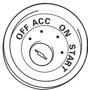
ACC position

No ACC position
Fig. 1
- The black lead is ground. Please ground this lead separately from the ground of high-current products such as power amps. If you ground the products together and the ground becomes detached, there is a risk of damage to the products or fire.
- Cords for this product and those for other products may be different colors even if they have the same function. When connecting this product to another product, refer to the supplied Installation manuals of both products and connect cords that have the same function.
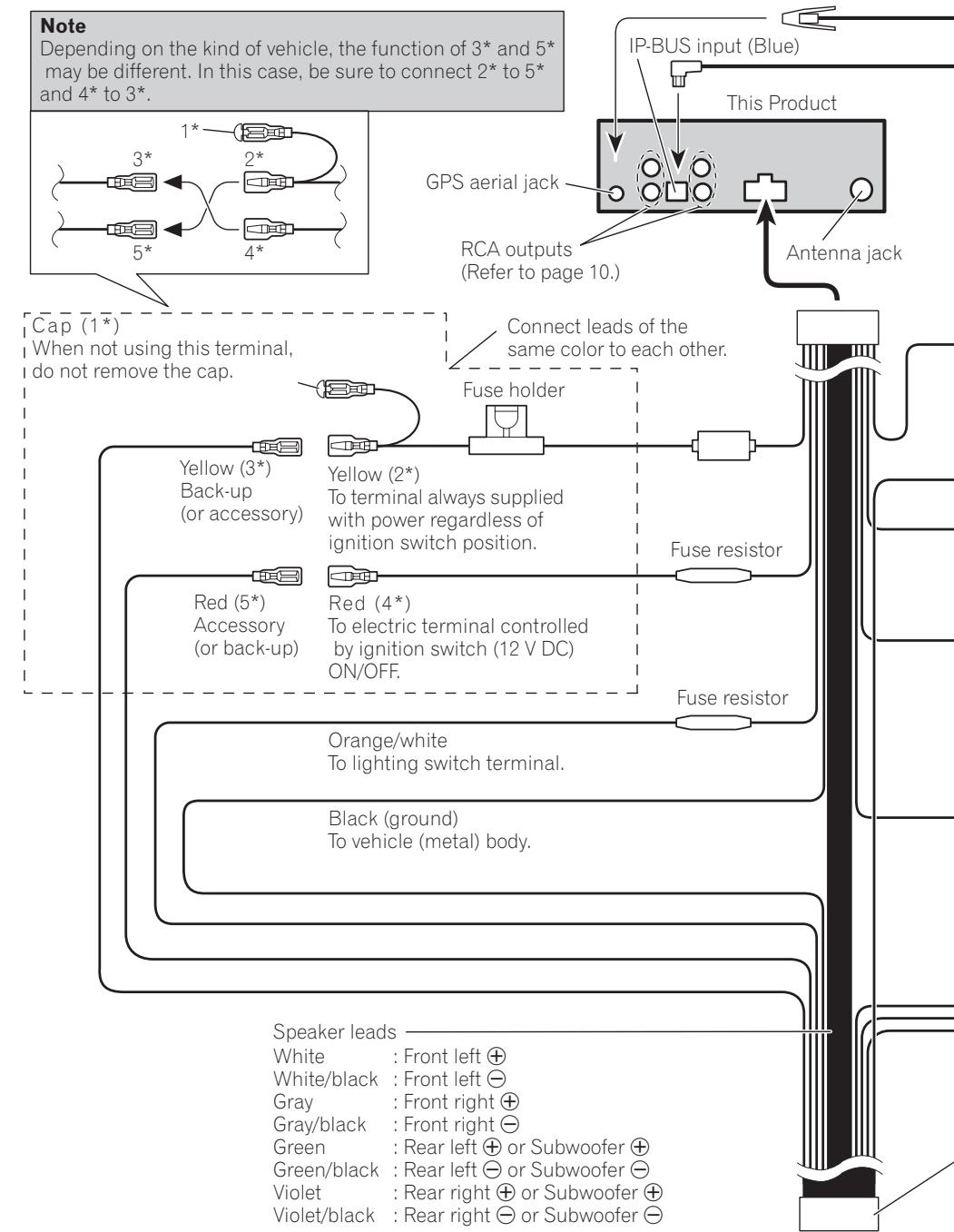
Power cable connection

Fig. 2
Connecting to separately sold power amp


Fig. 3
System connection
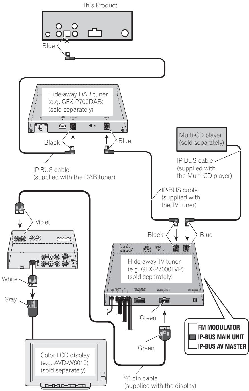
Fig. 4
Installation
Installing the unit

CAUTION
- PIONEER does not recommend that you install or service your navigation unit yourself. Installing or servicing the product may expose you to risk of electric shock or other hazards. Refer all installation and servicing of your navigation unit to authorised PIONEER service personnel.
- Before finally installing the unit, connect the wiring temporarily, making sure it is all connected up properly, and the unit and the system work properly.
- Use only the parts included with the unit to ensure proper installation. The use of unauthorized parts can cause malfunctions.
- Install the unit where it does not get in the driver's way and cannot injure the passenger if there is a sudden stop, like an emergency stop.
- Consult with your nearest dealer if installation requires the drilling of holes or other modifications of the vehicle.
- When using screws, do not allow them to come into contact with any electrical lead. Vibration may damage wires, leading to a short circuit or other damage to the vehicle.
- It is extremely dangerous to allow the GPS aerial lead to become wound around the steering column or gearstick. Be sure to install the unit in such a way that it will not obstruct driving.
-
Make sure that leads cannot get caught in a door or the sliding mechanism of a seat, resulting in a short circuit.
-
Please confirm the proper function of your vehicle's other equipment following installation of the navigation unit.
- The semiconductor laser will be damaged if it overheats, so don't install the unit anywhere hot — for instance, near a heater outlet.
- Install the main unit on a surface within +30 degrees to 0 degrees tolerance (within five degrees to the left or right of your vehicle's direction of travel). A surface tilted more than this would increase the errors in location display. (Fig. 5)

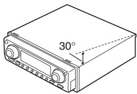
Fig. 5
- The cords must not cover up the area shown in the figure below. This is necessary to allow the amplifiers to radiate freely. (Fig. 6)

Do not close this area.
Fig. 6
Installation
To guard against electromagnetic interference
- In order to prevent interference, set the following items as far as possible from the main unit of this Navigation System, other cables or leads:
TV antenna and antenna lead
FM, MW/LW antenna and its lead
GPS aerial and its lead
In addition you should lay each antenna lead as far as possible from other antenna leads. Do not bind them together, lay them together, or cross them.
Such electromagnetic noise would increase the error for the location display.
Parts supplied

Main unit

Frame

Screw
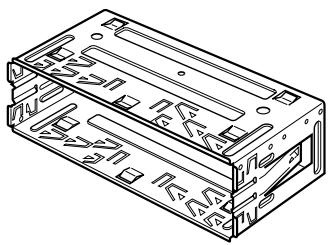
Holder

Extraction Key (2pcs.)

Rubber bush
Installation
Installation with the rubber bush

Holder
After inserting the holder into the dashboard, then select the appropriate tabs according to the thickness of the dashboard material and bend them.
(Install as firmly as possible using the top and bottom tabs. To secure, bend the tabs 90 degrees.)
Removing the unit
Fig. 7
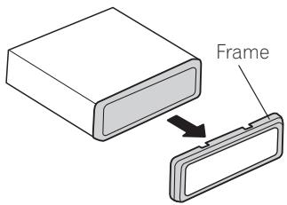
Pull out to remove the frame. (When reattaching the frame, point the side with a groove downwards and attach it.)

Fig. 8
Fig. 9
Installation
Installing the GPS aerial

CAUTION
- Do not cut the GPS aerial lead to shorten it or use an extension to make it longer. Altering the aerial cable could result in a short circuit.

Notes
- The aerial should be installed on a level surface where radio waves will be blocked as little as possible. Radio waves cannot be received by the aerial if reception from the satellite is blocked. Installation on the vehicle roof or boot lid is recommended to enable best reception.
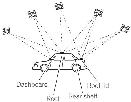
(Fig. 10)
Fig. 10
- When installing the GPS aerial inside the vehicle, be sure to use the metal sheet provided with your system. If this is not used, the reception sensitivity will be poor.
- Do not cut the accessory metal sheet. This would reduce the sensitivity of the GPS aerial.
- Take care not to pull the aerial lead when removing the GPS aerial. The magnet attached to the aerial is very powerful, and the lead may become detached.
- The GPS aerial is installed with a magnet. When installing the GPS aerial, be careful not to scratch the vehicle body.
- When installing the GPS aerial on the outside of the vehicle, always put it in the vehicle when going through an automatic vehicle wash. If it is left on the outside it may be knocked off and scratch the vehicle body.
- Do not paint the GPS aerial, as this may affect its performance.
When installing the aerial inside the vehicle (on the dashboard or rear shelf) (Fig. 11)
Affix the metal sheet on as level a surface as possible where the GPS aerial faces outside the window. Place the GPS aerial on the metal sheet. (The GPS aerial is fastened with its magnet.)

Fig. 11

Notes
- When attaching the metal sheet, do not cut it into small pieces.
- Some models use window glass that does not allow signals from GPS satellites to pass through. On such models, install the GPS aerial on the outside of the vehicle.
When installing the aerial outside the vehicle (on the body) (Fig. 12)
Put the GPS aerial in a position as level as possible, such as on the roof or boot lid. (The GPS aerial is fastened with a magnet.)
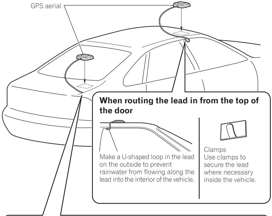
When routing the lead in from inside the boot

Fig. 12
Setting the Navigation
Calibration
Before using the navigation, perform calibration and language definition referring to the Installation Manual.

After switching on the unit, the status of the GPS antenna or of the GPS reception will be indicated on the right of the display. Four different messages may appear:
- GPS OK: The navigation CD can be inserted. GPS reception is already available.
- GPS WAIT: It is necessary to wait for GPS reception. Waiting is required until GPS OK is displayed (vehicle must be outdoors). The navigation CD can be inserted.
- GPS ANTENNA ERROR: The GPS antenna is not properly connected.
- GPS MODULE ERROR: If this message is displayed, please contact the hotline.
1 Insert the navigation CD to install the software for the navigation system.
2 After installing the navigation software, press the NAVI/OK button.
The next display appears.
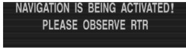
3 Press the BACK button to access the system settings.
The language selection is then requested.
4 Select the language using the rotary stick.
The language selection is confirmed by pressing the control and the language is installed.

5 Select the voice using the rotary stick.
You can choose either a male or a female voice for some languages.
The voice is confirmed and installed by pressing the control.

6 After installation, press the NAVI/OK button to confirm.
Setting the Navigation
7 After installing the language, you have to wait for GPS reception before commencing the calibration journey.

Notes
- During the check, the vehicle must be outdoors and the GPS antenna must have a clear view of all directions. It may take a few minutes until sufficient GPS reception is available. The next display appears during this period. A calibration journey is requested when sufficient GPS reception is available.
| CALIBRATION | RIDE CAN | START |
| WHEEL: | 3451, | GYRO: 30, SAT: 4 |
| 48:52.53 N | 08:30.25 E | |
- In order to minimise the waiting period for sufficient GPS reception, the vehicle should not moved during this time. The unit must be switched on.
8 Before commencing the calibration journey, the sensor tests should be carried out.
To invoke service garage mode, press multifunction button 3 and 5 simultaneously.

9 The calibration journey can be commenced after successful completion of the tests.
Service garage mode is quit by repeatedly pressing the NAVI/OK button.
| CALIBRATION | RIDE | CAN | START |
| WHEEL: | 3451, | GYRO: | 30, SAT: 4 |
| 48:52, 53 N | 08:30, 25 E | | |

Notes
- The calibration journey should not take place on a motorway, but should include as many turnings as possible. The next display appears during the calibration journey.
- When calibration status 2 has been reached, the main navigation menu is displayed and the unit is ready for operation. Final precision is only achieved after a further journey (calibration status 3).
- If the unit is switched off during the calibration journey, language installation is requested when the unit is switch on again. To proceed with reinstallation, press the NAVI/OK button.
- For correct navigation on routes with time-dependent traffic guidance, the time should be correctly set as described under System settings in the operation manual.
Setting the Navigation
Service garage mode
1 Switch on the unit. (see operation manual)
2 If the unit is already calibrated, select the main navigation menu by pressing the NAVI/OK button.

3 Press the BACK button to access the system settings.
4 Press multifunction button 3 and 5 simultaneously.
Service garage mode is requested.

The following functions can be selected in service garage mode:

CALIBRATION RIDE - display for calibration journey
- GPS INFO - GPS function test
CALIBRATION - function for deleting the calibration or a calibration specification
- SENSORS - sensor function test
- VERSION - the status of the navigation CD is displayed
- SPEECH TEST - voice test
- MODULE TEST - internal component test
- DEMO - demo mode selection
By turning the rotary stick, select the desired entry (all capital letters) and press to confirm.

Setting the Navigation
Checking the vehicle and system sensors or functions
Testing the voice
A test programme is due to test the voice.
1 In service garage mode, select SPEECH TEST with the rotary stick and press to confirm.
The announcement "Please insert navigation CD" is given.
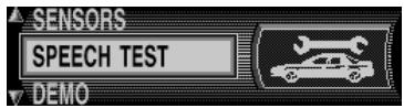
2 By pressing the NAVI/OK button, the announcement can be repeated.
3 After completing the test, press the BACK button.
The unit switches back to service garage mode.
Testing the system components (unit test)
A test programme automatically tests the internal components of the navigation system.
1 In service garage mode, select MODULE TEST with the rotary stick and press to confirm.

2 If OK is displayed, press the NAVI/OK button.
The unit switches back to service garage mode.
Setting the Navigation
Function test of the speed signal, reverse signal, internal sensors
1 In service garage mode, select SENSORS with the rotary stick and press to confirm.

2 Move the vehicle several metres forwards or backwards for the speed signal function test.
The number after WHEEL: should increase (even at a low speed).
The number after WHEEL: should not increase if idling or accelerating when the vehicle is parked.

The values after X : and Y : should not change.
3 Engage the reverse gear for the reverse signal function test.
The number after REVERSE: should jump from 0 to 1 (1 to 0).
4 In order to quit the sensor test, press the NAVI/OK button.
The unit switches back to service garage mode.
Function test of the GPS antenna
1 In service garage mode, select GPS-INFO with the rotary stick and press to confirm.
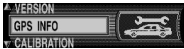
If GPS reception is functioning properly, the number of satellites received (e.g. SAT 5), the date and time (e.g. 13.03.99 14:56:08) and the type of locationing currently possible FIX: (e.g. 3D) are displayed.

- At least FIX 2D is required for quick and successful calibration. A certain amount of time may be required to reach this value (do not move the vehicle during this period).
2 In order to quit the GPS test, press the NAVI/OK button.
The unit switches back to service garage mode.
Setting the Navigation
Calibration
Calibration
After commissioning, a calibration journey is required. During the journey, the speedometer signal is adapted to the vehicle-specific data and the gyro sensors are adapted to the installation position of the unit.
The distance to be covered depends on the type of vehicle and the local conditions.

Note
- The navigation system is only ready for operation on completion of the calibration journey. The main navigation menu is displayed. Final precision is only achieved after a further journey (calibration status 3).
1 In service garage mode, select CALIBRATION RIDE using the rotary stick and press to confirm.

The calibration status (e.g. STATUS: 2) and the type of locationing (e.g. 3D) are displayed. After completing calibration, the street in which you are currently driving is displayed (provided that it is digitised) instead of WHEEL and REVERSE.
Deleting the calibration
If the navigation system is removed from one vehicle and installed in another vehicle, it must be calibrated. However, to do so, the current calibration data must be deleted.
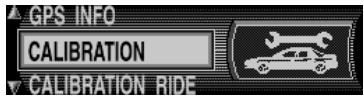
1 In service garage mode, select CALIBRATION using the rotary stick and press to confirm.
2 Using the rotary stick, select DELETE and press to confirm.
The calibration is deleted and the unit returns to service garage mode.

Calibration setting

Note
- Calibration settings should only be made when the values to be entered are known. The unit cannot make correct route calculations if incorrect values are entered.
1 In service garage mode, select CALIBRATION using the rotary stick and press to confirm.

Setting the Navigation
2 Using the rotary stick, select MODIFY and press to confirm.
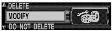
3 Unit rotation can be selected in degrees by turning the rotary stick and pressing to confirm.
HORIZONTAL UNIT TURNING
+0
Unit rotation corresponds to horizontal rotation. A positive value means rotation of the front of the unit towards the driver (LHD).
4 The unit inclination can now be selected in degrees by turning the rotary stick and pressing to confirm.
UNIT INCLINATION
+0
Unit inclination corresponds to vertical inclination. A positive value means upward inclination of the front of the unit.
5 The number of wheel impulses per wheel revolution (if known) can then be selected by turning the rotary stick and pressing to confirm.

If the number of wheel impulses per wheel revolution is not known, UNKNOWN must be selected. The entering of tyre data is than not available.
6 The previously entered data is displayed once more. If the data entered is correct, press the NAVI/OK button.
If correction is necessary, select MODIFY by turning the rotary stick and press to confirm. The values can then be re-entered.
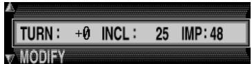
Once the previously entered data is confirmed, the tyre data can be entered or self-calibration can be started.
7 To enter the tyre data, select INPUT TYRE VALUES by turning rotary stick and press to confirm.

Setting the Navigation
8 Enter the required tyre size using the rotary stick and confirm the entry by pressing for more than 2 seconds.

The left "R" cannot be entered. 3 numbers must be entered before and after the slashes. Insert a "0" before any missing numbers.
Example:
Specification in vehicle registration papers:
185/55R15 81T
Entry into unit: 185/055/015
Selected between NEW TYRE TREAD and USED TYRE TREAD by turning the rotary stick to enter the approximate tread depth value. Press the NAVI/OK button to make a selection.

9 The previously entered data is displayed once more. If the data entered is correct, press the NAVI/OK button.
If correction is necessary, select MODIFY by turning the rotary stick and press to confirm.
The values can then be re-entered.

10 After confirming the tyre data or the previously confirmed point START SELF-CALIBRATION, the next display appears.

11 After 8 seconds, the unit switches to the main navigation menu or the calibration journey is requested.
The unit is now in calibration status 2. Absolute precision is, however, only achieved from calibration status 3.
Demo mode
Demo mode is intended for demonstration purposes. A fixed location is given to the unit (Hamburg Werderstraße).
1 In service garage mode, select DEMO using the rotary stick and press to confirm.
Select between ON and OFF by briefly pressing the NAVI/OK button. By holding down the rotary stick, the setting is adopted.
You can now enter a destination as described in the operation guide.
2 To switch off demo mode, select OFF with the rotary stick and press to confirm.


PIONEER ELECTRONICS (USA) INC.
P.O. Box 1540, Long Beach, California 90801-1540, U.S.A.
TEL: (800) 421-1404
PIONEER EUROPE NV
Haven 1087, Keetberglaan 1, B-9120 Melsele, Belgium
TEL: (0) 3/570.05.11
PIONEER ELECTRONICS ASIACENTRE PTE. LTD.
253 Alexandra Road, #04-01, Singapore 159936
TEL: 65-6472-1111
PIONEER ELECTRONICS AUSTRALIA PTY. LTD.
178-184 Boundary Road, Braeside, Victoria 3195, Australia
TEL: (03) 9586-6300
PIONEER ELECTRONICS OF CANADA, INC.
300 Allstate Parkway, Markham, Ontario L3R OP2, Canada
TEL: (905) 479-4411
PIONEER ELECTRONICS DE MEXICO, S.A. de C.V.
San Lorenzo 1009 3er. Piso Desp. 302
Col. Del Valle Mexico, D.F. C.P. 03100
TEL: 55-5688-52-90
Published by Pioneer Corporation.
Copyright © 2002 by Pioneer Corporation.
All rights reserved.
Publication de Pioneer Corporation.
Copyright © 2002 Pioneer Corporation.
Tous droits de reproduction et de traduction réservés.