
PDP-502MXE - TV PIONEER - Free user manual and instructions
Find the device manual for free PDP-502MXE PIONEER in PDF.

| Product Type | Plasma Television |
| Brand | PIONEER |
| Model | PDP-502MXE |
| Screen Size | 50 inches (diagonal) |
| Resolution | 1280 x 768 pixels (XGA) |
| Native Aspect Ratio | 16:9 (widescreen) |
| Dimensions (without stand) | 1218 x 714 x 98 mm |
| Dimensions (with stand) | 1218 x 737 x 300 mm |
| Weight (with stand) | 40.3 kg |
| Power Supply | 100-240 V AC, 50/60 Hz |
| Standby Power Consumption | 0.6 W |
| Rated Power Consumption | 5.4 A (100 V) - 2.2 A (240 V) |
| Video Inputs | INPUT3: 5 x BNC (R/G/B, G ON SYNC); INPUT4: Mini D-sub 15-pin (R/G/B) |
| Audio Inputs | INPUT3: 2 x RCA (L/R); INPUT4: 1 x stereo mini-jack |
| Audio Outputs | 1 x stereo mini-jack (line output); speaker terminals (8-16 Ω, 2 W + 2 W) |
| Energy Saving Functions | POWER SAVE (MODE1, MODE2, OFF) |
| Picture Adjustments | Contrast, brightness, RGB levels, position, frequency, phase, ABL, H/V Enhance |
| Supplied Accessories | Remote control, batteries, cleaning cloth, quick fasteners, cable ties, mounting brackets, screws |
| Operating Temperature | 0 to 40 °C |
| Safety | Do not expose to moisture; use only PDK-5001 stand; professional installation recommended |
Frequently Asked Questions - PDP-502MXE PIONEER
User questions about PDP-502MXE PIONEER
0 question about this device. Answer the ones you know or ask your own.
Ask a new question about this device
Download the instructions for your TV in PDF format for free! Find your manual PDP-502MXE - PIONEER and take your electronic device back in hand. On this page are published all the documents necessary for the use of your device. PDP-502MXE by PIONEER.
USER MANUAL PDP-502MXE PIONEER
If you would like to view a video signal with this unit, please make the necessary connections to the optional video box, PDA-5001.
François
The lightning flash with arrowhead symbol, within an equilateral triangle, is intended to alert the user to the presence of uninsulated "dangerous voltage" within the product's enclosure that may be of sufficient magnitude to constitute a risk of electric shock to persons.
CAUTION
RISK OF ELECTRIC SHOCK
DO NOT OPEN
CAUTION:
TO PREVENT THE RISK OF ELECTRIC SHOCK,DO NOT REMOVE COVER (OR BACK).NO USER-SERVICEABLE PARTS INSIDE.REFER SERVICING TO QUALIFIED SERVICE PERSONNEL.

The exclamation point within an equilateral triangle is intended to alert the user to the presence of important operating and maintenance (servicing) instructions in the literature accompanying the appliance.
Thank you very much for purchasing this PIONEER product. Before using your Plasma Display, please carefully read the "Safety Precautions" and these "Operating Instructions" so you will know how to operate the Plasma Display properly. Keep this manual in a safe place. You will find it useful in the future.
WARNING: TO PREVENT FIRE OR SHOCK HAZARD, DO NOT EXPOSE THIS APPLIANCE TO RAIN OR MOISTURE.
CAUTION: This product may be used only with Model PDK-5001 stand. Use with other stands may result in instability causing possible injury.
WARNING: THIS APPARATUS MUST BE EARTHED.
CAUTION: WHEN POSITIONING THIS EQUIPMENT ENSURE THAT THE MAINS PLUG AND SOCKET IS EASILY ACCESSIBLE.
WARNING:
This is a Class A product. In a domestic environment this product may cause radio interference in which case the user may be required to take adequate measures.
To ensure proper heat radiation, distance the unit slightly from other equipment, walls, etc. (normally mode than 10cm ). Avoid the following installations which will block vents and cause heat to build up inside, resulting in fire hazards.
- Do not attempt to fit the unit inside narrow spaces where ventilation is poor
- Do not place on carpet
- Do not cover with cloth, etc.
- Do not place on its side
- Do not place it upside down
- If planning special installation such as fitting close to the wall, placing it horizontally, etc., be sure to consult your Pioneer dealer first.
Notes on Installation Work:
This product is marketed assuming that it is installed by qualified personnel with enough skill and competence. Always have an installation specialist or your dealer install and set up the product. PIONEER cannot assume liabilities for damage caused by mistake in installation or mounting, misuse, modification or a natural disaster.
Note for Dealers:
After installation, be sure to deliver this manual to the customer and explain to the customer how to handle the product.
The following symbols are found on labels attached to the product. They alert the operators and service personnel of this equipment to any potentially dangerous conditions.

WARNING
This symbol refers to a hazard or unsafe practice which can result in personal injury or property damage.

CAUTION
This symbol refers to a hazard or unsafe practice which can result in severe personal injury or death.
- Incorporation of high performance XGA wide plasma panel.
The XGA wide panel incorporates pioneering developments that have allowed realization of more than 2.5 times the data capacity of the VGA panel used at the TV broadcasting level until now*. With a definition of 1280 pixels horizontal and 768 pixels vertical, the XGA wide panel provides unsurpassed reproduction of a wide range of images from personal computers.
- When the screen aspect is 4:3
VGA: 640 pixels x 480 pixels
XGA: 1024 pixels x 768 pixels
Achievement of XGA class high level luminance
Even in the case of luminance, which is difficult to keep consistent with the level of definition, using originally developed PIONEER technology for optimization, top level luminance has been achieved at this definition.
- Realization of thin 9.8cm unit depth while retaining a maximum class level 50 inch screen
As well as producing a 50 inch wide screen, which has been difficult to do with a direct view CRT, the extremely thin 9.8 cm unit depth size opens up completely new possibilities to how viewing rooms may be designed.
Unlimited placement possibilities
Designed to be attached to a wall, set on a table top stand or placed on a floor rack, this unit can be installed many ways.
- Optional line (sold separately)
(For details, please consult the dealer where this unit was purchased.)
1 Table top stand : Stand designed specifically for PDP-502MXE table top placement.
2 Wall installation unit : Wall installation bracket designed as a wall interface for securing the unit to various types of wall construction formats.
CAUTION:
This product may be used only with Model PDK-5001 stands.
Use with other stands may result in instability causing possible injury.
3 Speaker system designed specifically for plasma displays (width: 7.4 cm)
: With the adoption of a vertical twin system designed with a 2.5 cm domed conical tweeter in the center and newly developed 4.5 cm wide oval shaped units arranged vertically, sound field orientation has been greatly improved. Although the cabinet depth is only 7.4 cm, a rich, dynamic sound is produced. (When speakers are attached, the operation panel on this unit is not operable.)
Designed to conserve energy
This product has been designed to minimize power consumption when the power is in standby. The value of the power consumption in standby mode is 0.6W .
Contents
Safety Precautions
Before Proceeding 2
How to Use This Manual 2
Checking supplied accessories 3
Part Names and Functions 4
Main unit 4
Remote control unit 5
Connection panel 6
Installation and Connections 8
Installation of the unit 8
Connection to a personal computer 10
Audio connections 11
Control cord connection 11
Power cord connection 12
How to route cables 12
Setting Up the System 13
Setup after connection 13
Operations 14
Selecting an input source 14
Screen size selection 16
POWER SAVE 17
Display Panel Adjustments 18
Adjusting the picture quality. 18
Adjusting the display image 19
Making the PC image brighter (ABL) 20
Making the PC image clearer (H/V ENHANCE) 21
Resetting the unit to factory set defaults 21
Additional Information 22
Cleaning 22
Inserting the batteries in the remote control unit 22
Operating range of the remote control unit ... 23
Troubleshooting 23
Specifications 25
Supplement 1 26
Supplement 2 27
Explanation of Terms 27
How to Use This Manual
This manual is set up to follow the course of actions and operations in the order that would seem most logical for someone setting up this unit.
Once the unit has been taken out of the box, and it has been confirmed that all the parts have been received, it may be beneficial to look over the section "Part Names and Functions" starting on page 4 to become acquainted with the plasma monitor and remote control unit, as their respective buttons and controls will be referred to throughout this manual.
The section "Installation and Connections" starting on page 8 covers all the necessary points regarding installation of the plasma display and connections to a personal computer (PC).
The section "Setting Up the System" starting on page 13 covers the necessary on-screen menu settings to establish correct linkage between the plasma display and connected components. Depending on the connections made, this section may or not be necessary.
The remainder of the sections in this manual is dedicated to the basic operations associated with selecting a source component up to the more complex operations associated with adjusting the plasma display picture to match the requirements of specific components and personal preferences.
About operations in this manual
Operations in this manual are outlined in step by step numbered procedures. Most of the procedures are written in reference to the remote control unit unless the button or control is only present on the main unit.
However, if a button or control on the main unit has the same or similar name as that on the remote control unit, that button can be used when performing operations.
The following example is an actual operation that shows how one might set the vertical position of the screen. The screens shown at each step are provided as a visual guide to confirm that the procedure is proceeding as it should. Please familiarize yourself with this process before continuing on with the rest of this manual.
1 Press MENU to display the menu screen.
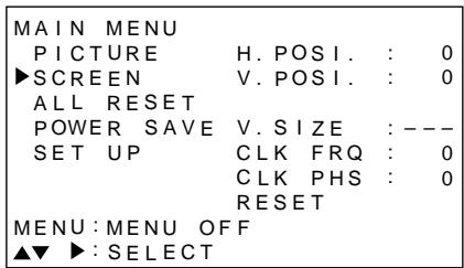
2 Press / to select SCREEN.
| MAIN MENU | |
| PICTURE | H. POSI.: 0 |
| SCREEN | V. POSI.: 0 |
| ALL RESET | |
| POWER SAVE | V. SIZE: -- |
| SET UP | CLK FRQ: 0 |
| CLK PHS: 0 | |
| RESET | |
| MENU: MENU OFF | |
| ▲▼ ▲: SELECT | |
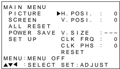
3 Press
| MAIN MENU | |
| PICTURE | H. POSI.: 0 |
| SCREEN | V. POSI.: 0 |
| ALL RESET | |
| POWER SAVE | V. SIZE: -- - - |
| SET UP | CLK FRQ: 0 |
| CLK PHS: 0 | |
| RESET | |
| MENU: MENU OFF | |
| ▲▼▲: SELECT SET: ADJUST | |
4 Press / to select V. POSI.
| MAIN MENU | |
| PICTURE | H. POSI.: 0 |
| SCREEN | ▼V. POSI.: 0 |
| ALL RESET | |
| POWER SAVE | V. SIZE: -- |
| SET UP | CLK FRQ: 0 |
| CLK PHS: 0 | |
| RESET | |
| MENU: MENU OFF | |
| ▲▼▲: SELECT SET: ADJUST | |
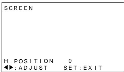
5 Press SET to display the adjustment screen for the selected item.
| SCREEN | |
| V. POSITION | 0 |
| ▲▼: ADJUST | SET: EXIT |
6 Press / to adjust the value.
Checking supplied accessories
Check that the following accessories were supplied.
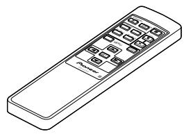
① Remote control unit
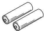
② AA (R6) batteries x 2
③ Cleaning cloth (for wiping front panel)

④ Speed clamp x 2
⑤ Bead band x 2

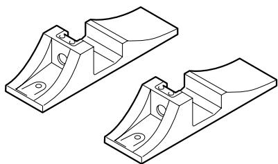
⑥ Display stand x 2
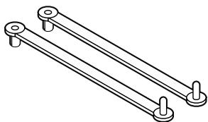
⑦ Washer (large) x 2

⑧ Washer (small) x 2

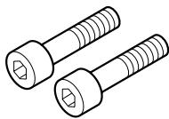
⑨ Hex hole bolt x 2
Remote control unit case
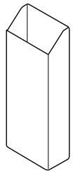
Use as a holder for the remote control unit. When attaching to the rear of the main unit, be careful not to cover the vents.
- Operating Instructions
Main unit
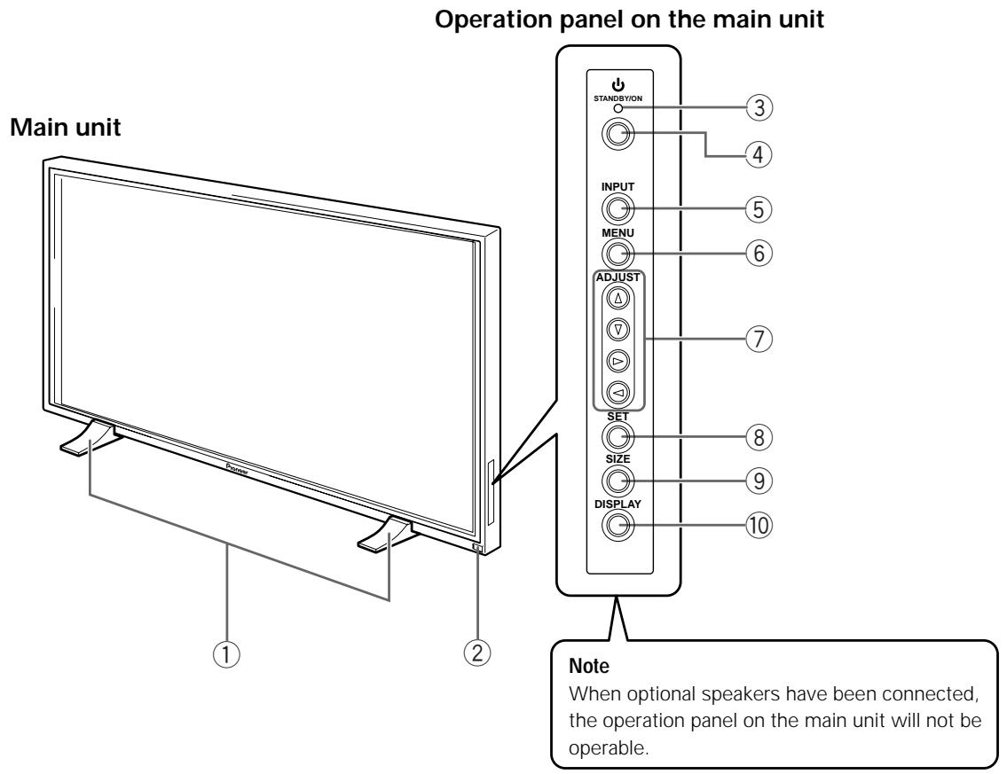
Main unit
① Display stand
② Remote control sensor
Point the remote control toward the remote sensor to operate the unit (page 23).
Operation panel on the main unit
③ STANDBY/ON indicator
This indicator is red during standby mode, and turns to green when the unit is in the operation mode (page 14).
(4) STANDBY/ON button
Press to put the display in operation or standby mode (page 14).
⑤ INPUT button
Press to select input (page 14).
(6) MENU button
Press to open and close the on-screen menu (pages 13 to 21).
⑦ ADJUST ( / / )_ buttons
Use to navigate menu screens and to adjust various settings on the unit.
Usage of cursor buttons within operations is clearly indicated at the bottom of the on-screen menu display (pages 13 to 21).
⑧ SET button
Press to adjust or enter various settings on the unit (pages 13 to 21).
⑨ SIZE button
Press to manually select the screen size (page 16).
10 DISPLAY button
Press to view the unit's current input and setup mode (page 15).
Remote control unit
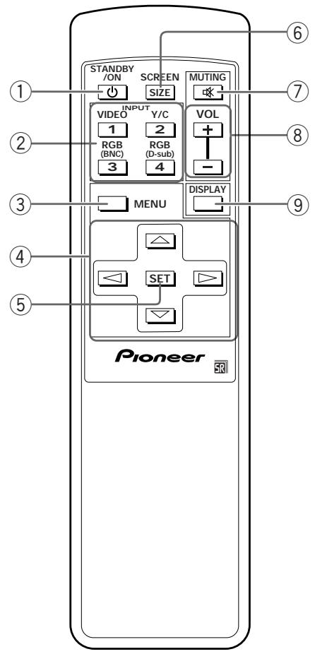
① STANDBY/ON button
Press to put the unit in operation or standby mode (page 14).
② INPUT buttons
Use to select the input (page 14).
③ MENU button
Press to open and close the on-screen menu (pages 13 to 21).
④ ADJUST ( / / ) / ) buttons
Use to navigate menu screens and to adjust various settings on the unit.
Usage of cursor buttons within operations is clearly indicated at the bottom of the on-screen menu display (pages 13 to 21).
⑤ SET button
Press to adjust or enter various settings on the unit (pages 13 to 21).
⑥ SCREEN SIZE button
Press to manually select the screen size (page 16).
(7) MUTING button
Press to mute the volume (page 15).
⑧ VOL (+/-) buttons
Use to adjust the volume (page 15).
⑨ DISPLAY button
Press to view the unit's current input and setup mode (page 15).
Connection panel
For details regarding a specific connection format, refer to the page written in parenthesis.
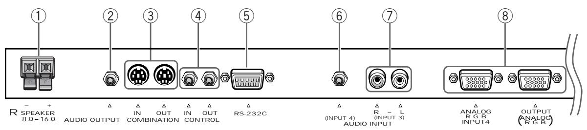
① SPEAKER (R) terminal
For connection of an external right speaker. Connect a speaker whose impedance is 8 -16 Ω (page 11).
Use to output the audio of the selected source component connected to this unit to an AV amplifier or similar component (page 11).
(3) COMBINATION IN/OUT
DO NOT MAKE ANY CONNECTIONS TO THESE TERMINALS.
These terminals are used in the factory setup.
(4) CONTROL IN/OUT
For connection of PIONEER components that bear the mark. Making CONTROL connection enables control of this unit as a component in a system (page 11).
⑤ RS-232C
DO NOT MAKE ANY CONNECTIONS TO THIS TERMINAL.
This terminal is used in the factory setup.
Use to obtain sound when INPUT4 is selected. Connect the audio output jack of components connected to INPUT4 to this jack (page 11).
⑦ AUDIO INPUT (Pin jack)
Use to obtain sound when INPUT3 is selected. Connect the audio output jack of components connected to INPUT3 to these jacks (page 11). NOTE: The left audio channel (L) jack is not compatible with monaural input sources.
⑧ INPUT4
For connection of a personal computer (PC). Make sure that the connection made corresponds to the format of the signal output from the connected component. Use the INPUT4 OUTPUT terminal to output the RGB signal to an external monitor or other component (page 10).
Note: The RGB signal will not be output from the INPUT4 OUTPUT terminal when the main power of this unit is off or in standby mode.

⑨ INPUT3
For connection of a personal computer (page 10).
Synchronizing signal impedance selector switch
Depending on the connections made at INPUT3, it may be necessary to set this switch to match the output impedance of the personal computer's synchronization signal.
When the output impedance of the personal computer's synchronization signal is above 75 , set this switch to the 2.2k position (page 10).
11 MAIN POWER switch
Use to switch the main power of the unit on and off.
⑫ AC INLET
Use to connect a power cord to an AC outlet (page 12).
⑬ SPEAKER (L) terminal
For connection of an external left speaker. Connect a speaker that has an impedance of 8 -16 Ω. (page 11)
Installation of the unit
Installation using the supplied display stand
Be sure to fix the supplied stand to the installation surface.
Use commercially available M8 bolts that are 25 ~mm longer than the thickness of the installation surface.
1 Fix the supplied stand to the installation surface at each of the 4 prepared holes using commercially available M8 bolts.
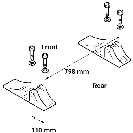
2 Insert the supplied washer (large) into the stand.
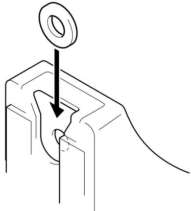
3 Take off the hole rivets and ' of this unit using a screwdriver or a coin.
4 Set this unit in the stand.
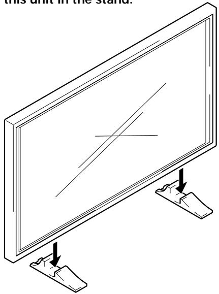
5 Fix this unit using the supplied washer and bolt.
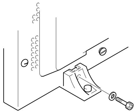
Use a 6 mm hex wrench to bolt them.

CAUTION
Because this unit weighs about 40kg and has little depth making it unstable, please use 2 people or more when packing, carrying or installing.
Installation using the optional PIONEER stand or installation bracket
- Please be sure to request installation or mounting of this unit or the installation bracket by an installation specialist or the dealer where purchased.
- When installing, be sure to use the bolts provided with the stand or installation bracket.
- For details concerning installation, please refer to the instruction manual provided with the stand or installation bracket.
Installation using accessories other than the PIONEER stand or installation bracket (sold separately)
- When possible, please install using parts and accessories manufactured by PIONEER. PIONEER will not be held responsible for accident or damage caused by the use of parts and accessories manufactured by other companies.
- For custom installation, please consult the dealer where the unit was purchased, or a qualified installer.
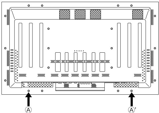
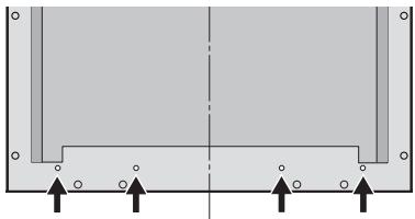
Wall-mount installation of the unit
This unit has been designed with bolt holes for wall-mount installation, etc.. The installation holes that can be used are shown in the diagram below. (Hole rivets can be removed by turning with a screwdriver, coin or similar tool.)
- Be sure to attach in 4 or more locations above and below, left and right of the center line.
- Use bolts that are long enough to be inserted 12 ~mm to 20 ~mm into the main unit from the attaching surface for both a holes and b holes. Refer to the side view diagram below.
- As this unit is constructed with glass, be sure to install it on a flat, unwarped surface.
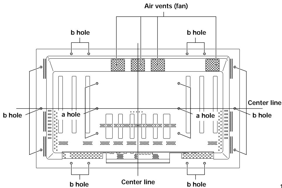
Rear view diagram
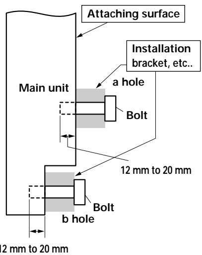
Side view diagram

CAUTION
To avoid malfunction, overheating of this unit, and possible fire hazard, make sure that the vents on the main unit are not blocked when installing. Also, as hot air is expelled from the air vents, be careful of deterioration and dirt build up on rear surface wall, etc..

CAUTION
Please be sure to use an M8 (Pitch = 1.25 mm) bolt. (Only this size bolt can be used.)

CAUTION
Because this unit weighs about 40kg and has little depth making it unstable, please use 2 people or more when packing, carrying or installing.

CAUTION
This unit incorporates a thin design. To ensure safety if vibrated or shaken, please be sure to take measures to prevent the unit from tipping over.
Connection to a personal computer
Connection method differs depending on the computer type. When connecting, please thoroughly read the computer's instruction manual.
Before making connections, be sure to make sure that the personal computer's power and this unit's main power is off.
For the PC input signals and screen sizes that this unit is compatible with, please refer to Supplement 1 (page 26).
Connection of separate SYNC analog RGB source
Make separate SYNC connections for a component that has RGB output separated into 5 output signals: green, blue, red, horizontal synchronization signal, and vertical synchronization signal.
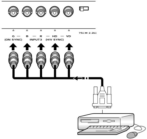
When connecting to INPUT3
When using INPUT3, set the impedance selector switch to match the output impedance of the connected component's synchronization signal.
When the output impedance of the component's synchronization signal is above 75 , set this switch to the 2.2k position.
On-screen setup is necessary after connection.
Please see page 13.
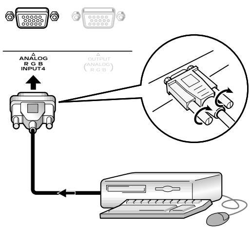
When connecting to INPUT4
Connect the cable corresponding to the shape of the input terminal on this unit and the personal computer's output terminal.
Secure by tightening the terminal screws on both units.
After connecting, on-screen setup is necessary.
Please see page 13.
Note
Depending on the type of computer model being connected, a conversion connector or adapter etc. provided with the computer or sold separately may be necessary.
For details, please read your PC's instruction manual or consult the maker or nearest dealer of your computer.
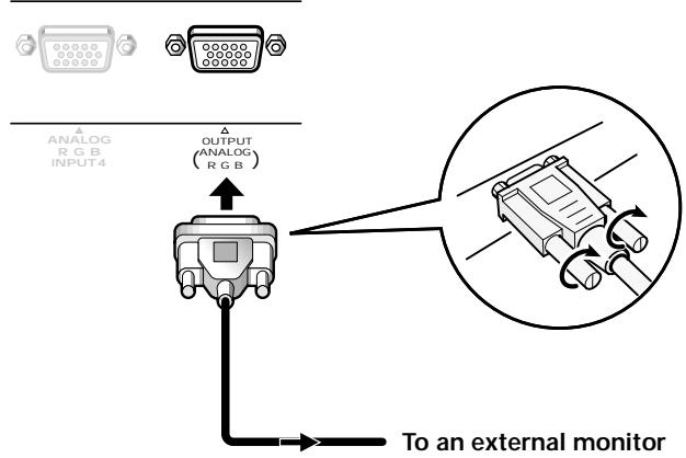
When connecting to INPUT4 (OUTPUT)
With this unit, it is possible to output the RGB signal to an external monitor or other component from the INPUT4 OUTPUT terminal.
Note
An RGB signal will not be output from the INPUT4 OUTPUT terminal when the main power of this unit is off or in standby.
Audio connections
Before making connections, be sure to check that the component's power and the unit's main power is off.
Connecting the speakers
This unit is equipped with speaker output jacks for connection to the speaker system (not supplied) specially designed for use with this unit. Refer to the illustrations below when making connections to the speaker terminals on this unit.

Twist exposed wire strands together.
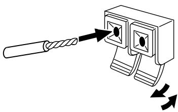
Push tab to the open position, and insert the wire. Then, close tab firmly to secure the wire in place.
Note
When making speaker connections, be sure to match the polarities (+ and -) of the speaker terminals on this unit and the corresponding terminals on the speakers. If the polarity is reversed, the sound will be unnatural and lack bass.
Making connections to the audio inputs on this unit
This unit features two audio inputs and one audio output. The following chart shows the inputs and the corresponding audio input jacks.
| Video input | Audio input jacks | Sound output |
| INPUT3 | Pin jacks (L/R) | Sound of the selected input is output from the • SPEAKER terminals • Stereo mini jacks (L/R). |
| INPUT4 | Stereo mini jack (L/R) |
Control cord connection
When control cord connections are made, remote control operation of connected PIONEER components that bear the logo mark is done through the remote sensor on this unit.
When the connection is made to the CONTROL IN jack on another unit, the remote sensor of that component will no longer receive signals. Point the remote control unit of the connected component at the remote control sensor on this unit to control.
Notes
- Make sure the power is turned off when making connections.
- Please complete all component connections before making control cord connections.
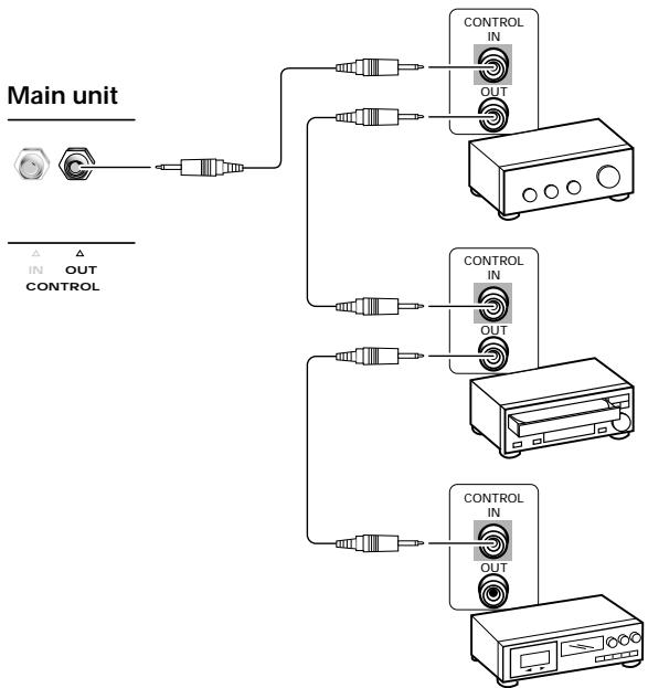
The control cables (not supplied) are monaural cables with mini plugs (no resistance).
Power cord connection
Connect a power cord after all component connections have been completed.
PDP-502MXE power cord ratings
Cord . Cross-sectional area 3 × 1.0 ~mm^2
(According to CEE 13)
Connector 10 A, 250 V
(According to EN60320 Sheet C13)
Plug International use (10 A, 250 V)
Example:
UK : UK 13 Amp Plug with rated 13 Amp fuse
(According to BS1363)
EURO:10A/16A250V(AccordingtoCEE7,1V)

CAUTION
- Do not use a power supply voltage other than that indicated (AC 100 - 240 V, 50/60 Hz) as this may cause fire or electric shock.
- For the plasma display, a three-core power cord with a ground terminal is used for efficiency protection. Always be sure to connect the power cord to a three-pronged grounded outlet and make sure that the cord is properly grounded. If you use a power source converter plug, use an outlet with a ground terminal and screw down the ground line.
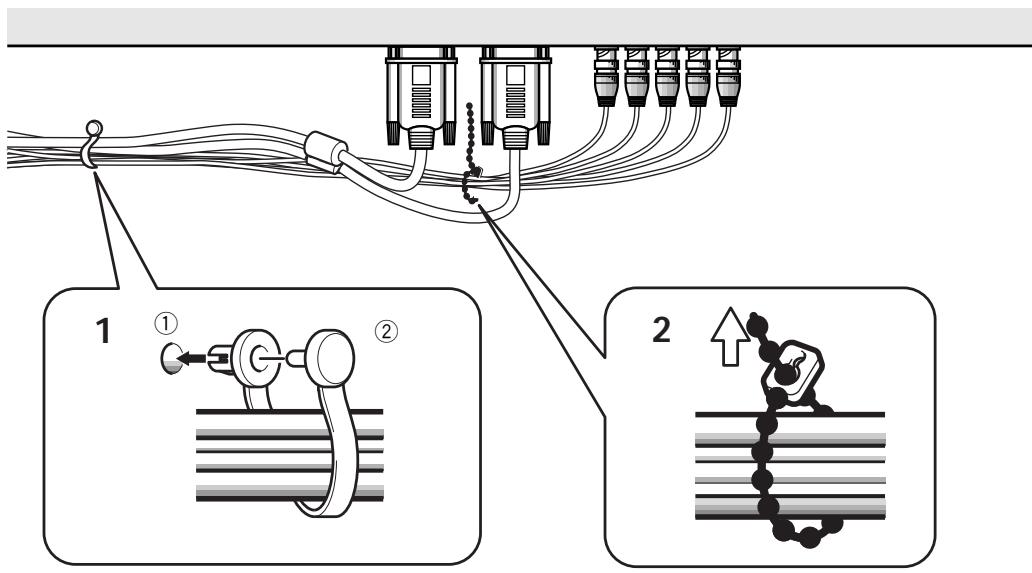
How to route cables
Speed clamps and bead bands are included with this unit for bunching cables together. Once components are connected, follow the following steps to route cables.
1 Organize cables together using the provided speed clamps.
Insert ① into an appropriate hole on the rear of the unit, then snap ② into the back of ① to fix the clamp.
Speed clamps are designed to be difficult to undo once in place. Please attach carefully.
To attach the speed clamps to the main unit
Connect the speed clamps using the 4 holes marked with below, depending on the situation.
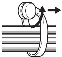
To remove speed clamps
Using pliers, twist the clamp 90^ and pull it outward. In some cases the clamp may have deteriorated over time and may be damaged when removed.
2 Bunch separated cables together and secure them with the provided bead bands.
Note
Cables can be routed to the right or left.
- As viewed from the rear of the display.
Setup after connection
After components have been connected to INPUT3 or INPUT4, on-screen setup is necessary.
Follow the procedure described below and make settings as they apply to the type of components connected.
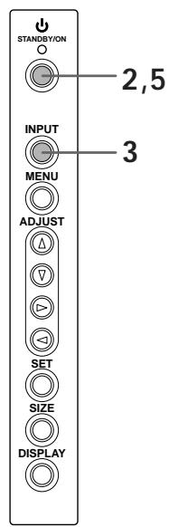
1 Switch MAIN POWER on the connection panel to the on position to turn on the unit's main power.
The STANDBY/ON indicator lights red.
2 Press STANDBY/ON to put the unit in the operation mode.
The STANDBY/ON indicator turns green.
3 Select INPUT3 or INPUT4.
4 Press MENU to display the menu screen.
The menu screen appears.
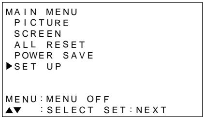
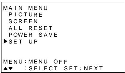
5 Press / to select SET UP, and press SET.
| MAIN MENU |
| PICTURE |
| SCREEN |
| ALL RESET |
| POWER SAVE |
| ▶SET UP |
| MENU: MENU OFF |
| ▲▼ : SELECT SET:NEXT |
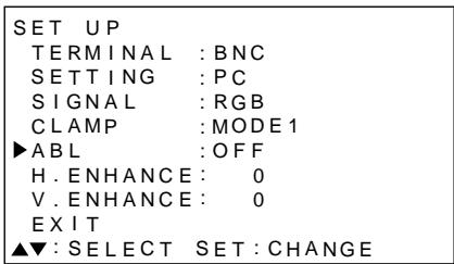
6 Press / to select SETTING.
| SET UP | |
| TERMINAL : BNC | |
| SETTING : PC | |
| SIGNAL : RGB | |
| CLAMP : MODE 1 | |
| ABL : OFF | |
| H. ENHANCE : 0 | |
| V. ENHANCE : 0 | |
| EXIT | |
| ▲▼: SELECT | SET: CHANGE |
7 Press SET to select "PC".
Depending on the input signal, this unit may not be able to make the correct setting. Make sure that this setting is set to "PC".
Note
Steps 6 to 7 are necessary when inputting a signal of horizontal frequency 31.5kHz /vertical frequency 60Hz .
For signals of other frequencies, settings are done automatically, and therefore cannot be performed.
8 When the setup is completed, press MENU to exit the menu screen.
Notes
- Make this setup for each input (INPUT3 and INPUT4).
- Please refer "G ON SYNC (CLAMP)" on this page for details concerning G ON SYNC setup.
G ON SYNC setup (CLAMP)
The RGB video signal is normally composed of 5 signals: R, G, B, HD and VD. With G ON SYNC connection, however, the signal is composed of 3 signals: R, G (G, HD and VD combined) and B.
If the personal computer being used is a model where G ON SYNC connection is carried out, on-screen setup is necessary.
Setup of G ON SYNC (CLAMP) connection
1 Press MENU to display the menu screen.
The menu screen appears.
2 Press / to select SET UP, and press SET.
| MAIN MENU PICTURE SCREEN ALL RESET POWER SAVE ▶SET UP |
| MENU: MENU OFF ▲▼ : SELECT SET:NEXT |
3 Press / to select CLAMP.
| SET UP | |
| TERMINAL : BNC | |
| SETTING : PC | |
| SIGNAL : RGB | |
| CLAMP : MODE 1 | |
| ABL : OFF | |
| H. ENHANCE : 0 | |
| V. ENHANCE : 0 | |
| EXIT | |
| ▲▼: SELECT SET: CHANGE |
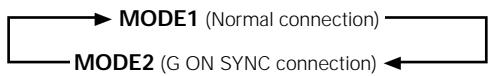
4 Press SET to select MODE2.
Mode selection will change as follows each time SET is pressed.
5 When the setup is completed, press MENU to exit the menu screen.
Notes
- Make this G ON SYNC setting for each applicable input (INPUT3 and INPUT4).
- When using this setup, be sure to carefully check the signal output of the personal computer you are using. For details, please refer to the instruction manual supplied with the personal computer you are connecting.
- If the screen becomes bright and turns a greenish color, set CLAMP to MODE2.
- G ON SYNC connection is carried out on some Macintosh computers.
Selecting an input source
This section explains the basic operation of this unit. Outlined on the following pages is how to turn the main power on and off, put this unit in the operation or standby mode and how to select connected components.
Note
INPUT1 and INPUT2 on the remote control unit can only be used when the optional video box, PDA-5001, is connected to this unit.
Before you begin, make sure you have:
- Made connections between this unit and a personal computer as described in the section "Installation and Connections" starting on page 8.
- Set up the on-screen menu to input signals from components connected to INPUT3 and INPUT4 as described in the section "Setting Up the System" on page 13.
Operation panel of the main unit
Remote control unit
1 Switch MAIN POWER on the main unit to the on position to turn the main power on.
The STANDBY/ON indicator lights red.
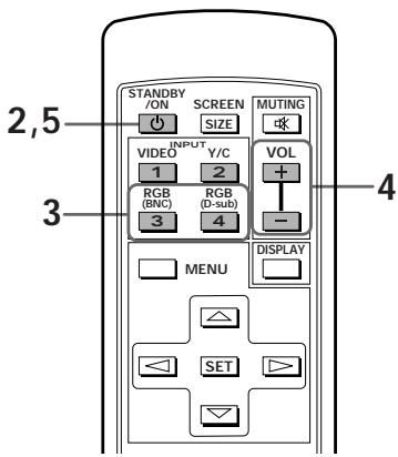
2 Press STANDBY/ON to put this unit in the operation mode.
The STANDBY/ON indicator turns green.
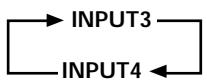
3 Press the appropriate INPUT button on the remote control unit or INPUT on the main unit to select the input.
On the main unit, input changes each time INPUT is pressed as follows.
- Input cannot be changed when a menu screen is displayed.
- When a signal from a personal computer is input, if the signal is not compatible with this unit, "OUT OF RANGE" will appear on the screen.
4 Use VOLUME + / - on the remote control unit to adjust the volume.
If no audio connections are made to this unit, this step is not necessary.
5 When viewing is finished, press STANDBY/ON to put the unit in standby mode.
The STANDBY/ON indicator will blink and then remain lit (red) indicating that the standby mode is engaged. Operation is not possible while the STANDBY/ON indicator is blinking (red).
6 Switch MAIN POWER on the main unit to the off position to turn the main power off.
CAUTION
Please do not leave the same picture displayed on the screen for a long time. Doing so may cause a phenomenon known as
"screen burn" which leaves a ghost, or residual, image of the picture on the screen.
To adjust the volume
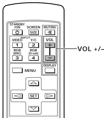
Use VOL + or VOL - to adjust the volume of the connected speakers.
To mute the sound
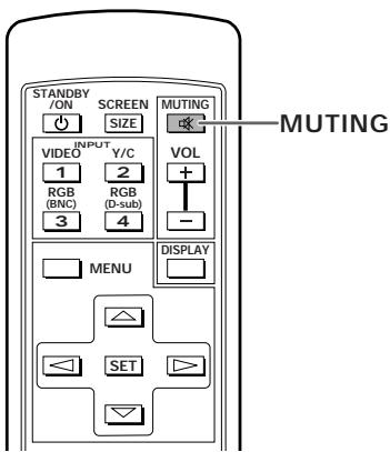
Press MUTING on the remote control unit.
Press MUTING again to restore the sound.
Muting is automatically canceled in about 8 minutes if no operations are performed during that time, and the volume level is adjusted to the minimum level.
Press VOL + or VOL - to adjust the volume at a desired level.
To confirm display settings
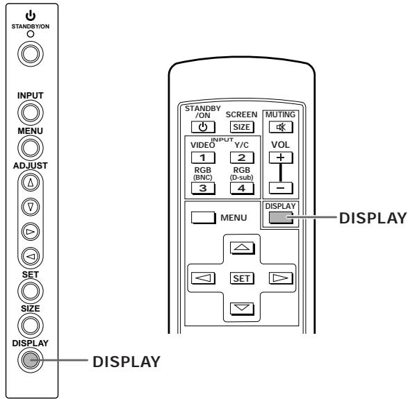
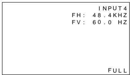
Press DISPLAY.
The currently selected input, screen size and vertical and horizontal frequencies will be displayed for approximately 3 seconds.
Note
The displayed vertical and horizontal frequencies are approximations, and may be slightly different from the actual values.
Screen size selection
Changing the screen size
The size of the picture or the picture's range projected on the screen can be changed between 4 screen sizes described in the table on this page.
Press SCREEN SIZE to select the size.
The screen size changes each time SCREEN SIZE on the remote control, or SIZE on the unit is pressed as follows.
For PC signals

(For screen sizes when the video signal of a personal computer is input, please see Supplement 1 on page 26.)
① ORIGINAL
The input signal and the screen maintain a dot to line ratio of 1:1 and is thus highly faithful to the source.
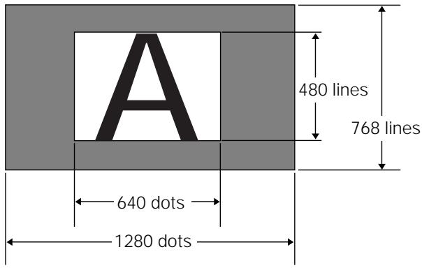
(Illustration shows 640 × 480 input.)
(2) 4:3 NORMAL
The display fills the screen as much as possible without altering the aspect ratio of the input signal.

Moving the screen position upward or downward
During personal computer input (1280 x 1024/60Hz only), when the ZOOM setting is selected, the position of the screen can be adjusted by using / .
③ FULL
The display is presented with a widescreen aspect ratio of 16:9 and fills the entire screen.

④ ZOOM
The ZOOM setting is available only during personal computer input (1280 x 1024/60 Hz only).
The input signal and the screen maintain a dot to line ratio of 1:1. Display is highly faithful to the source. However, in order to maintain the 1:1 ratio, a portion of the display will not appear on the screen.
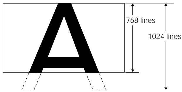
Use / to adjust the position of the video image on the screen.
POWER SAVE
Using the POWER SAVE function of this unit, the power mode can be automatically put in standby mode when a video or computer signal has not been detected.
(An indication will appear on the screen before the standby mode is engaged).
1 Press MENU to display the menu screen.
2 Press / to select POWER SAVE, and press SET.
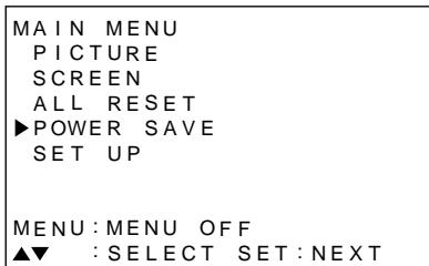
3 Press / to select "PC".
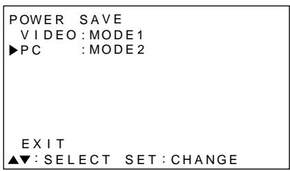
4 Press SET to select the POWER SAVE mode.
The PC POWER SAVE mode changes each time SET is pressed as follows.
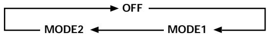
- When "OFF" is selected, this unit will stay in operation mode regardless of whether a synchronization signal is input or not.
- When "MODE1" is selected, this unit will be put in standby mode automatically if no new synchronization signal is input for 8 minutes.
- When "MODE2" is selected, this unit will be put in the power conservation standby automatically if no new synchronization signal is input. However, if the synchronization signal is restored, this unit is put back in operation mode.
5 When the setup is finished, press MENU to exit the menu screen.
Note
The POWER SAVE setting is common to INPUT3 and INPUT4.
To put the unit in operation mode again
Press STANDBY/ON on the main unit or remote control unit.
If "MODE 2" is selected for PC input, resuming PC operation or pressing INPUT on the main unit or remote control unit can also put the unit in operation mode again.
Adjusting the picture quality
1 Press MENU to display the menu screen.
2 Press / to select PICTURE, then press .
| MAIN MENU | ||
| ▲PICTURE | CONTRAST: | 0 |
| SCREEN | BRIGHT: | 0 |
| ALL RESET | R LEVEL: | 0 |
| POWER SAVE | G LEVEL: | 0 |
| SET UP | B LEVEL: | 0 |
| RESET | ||
| MENU: MENU OFF | ||
| ▲▼▲: SELECT | SET:ADJUST | |
3 Press / to select the adjustment item, then press SET.
| MAIN MENU | |
| PICTURE | CONTRAST: 0 |
| SCREEN | BRIGHT: 0 |
| ALL RESET | R LEVEL: 0 |
| POWER SAVE | G LEVEL: 0 |
| SET UP | B LEVEL: 0 |
| RESET | |
| MENU: MENU OFF | |
| ▲▼▲: SELECT SET:ADJUST | |
4 Press to adjust the picture quality as desired.
| PICTURE | |
| CONTRAST | 0 |
| ▲:ADJUST | SET:EXIT |
Pressing SET returns the display to the step 3 screen.
5 When the setup is finished, press MENU to exit the menu screen.
Note
Make these adjustments for both INPUT3 and INPUT4.
PICTURE mode adjustment items
Below are brief descriptions of the options that can be set in the PICTURE mode.
CONTRAST Adjust according to the surrounding brightness so that the picture can be seen clearly.
BRIGHT Adjust so that the dark parts of the picture can be seen clearly.
R LEVEL Adjust the amount of red in the picture.
G LEVEL Adjust the amount of green in the picture.
B LEVEL Adjust the amount of blue in the picture.
To reset PICTURE mode settings to the default
If settings have been adjusted excessively or the picture on the screen no longer appears natural, it may prove more beneficial to reset the PICTURE mode to default settings instead of trying to make adjustments under already adjusted conditions.
1 In step 3 in the previous procedure, press / to select RESET, then press SET.
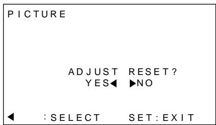
2 Press to select YES, and press SET.
All PICTURE mode settings are returned to the factory set default.
Adjusting the display image
1 Press MENU to display the menu screen.
2 Press / to select SCREEN, then press .
"---" is displayed if the adjustment is not available.
3 Press / to select the adjustment item, then press SET.
4 Press to carry out the adjustment.
Use / for the adjustments of V.POsiTION.
Pressing SET returns the display to the step 3 screen.
5 When adjustment is finished, press MENU to exit the menu screen.
Note
Make these adjustments for both INPUT3 and INPUT4.
SCREEN mode adjustment items
Below are brief descriptions of the options that can be set in the SCREEN mode.
H POSITION Adjust the picture's position to the left or right.
V POSITION Adjust the picture's position upward or downward.
CLK FREQ. Adjust letter breakup or noise on the screen. This setting adjusts the unit's internal clock signal frequency that corresponds to the input video signal.
CLK PHASE Adjust so that there is minimum flicker of screen letters or color misalignment. This setting adjusts the phase of the internal clock signal adjusted by the CLK FREQ. setting.
Notes
- When CLK FREQ. adjustment is carried out, the H.POITION setting may have to be re-adjusted.
- If the adjustment items in the SCREEN mode are adjusted excessively, the picture may not be displayed properly.
To reset SCREEN mode settings to the default
If settings have been adjusted excessively or the picture on the screen no longer appears natural, it may prove more beneficial to reset the SCREEN mode to default settings instead of trying to make adjustments under already adjusted conditions.
1 In step 3 in the previous procedure, press / to select RESET, then press SET.
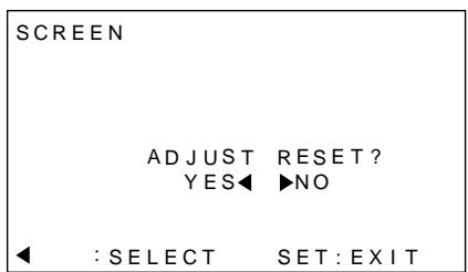
2 Press to select YES, and press SET.
All SCREEN mode settings are returned to the factory set default.
Making the PC image brighter (ABL)
Set this mode to "ON" to brighten the image during PC signal input. When ABL is set to "ON", the brightness of the image will change according to changes in the input signal. If you are bothered by changes to brightness during operation, set this mode to "OFF".
1 Press MENU to display the menu screen.
The menu screen appears.
2 Press / to select SET UP, then press SET.
3 Press / to select ABL.
4 Press SET to set the mode to "ON".
"ON" is set when this unit is shipped from the factory.
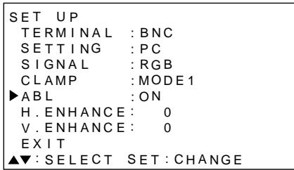
Each time SET is pressed, the settings change in the following order.

5 When the setup is finished, press MENU to exit the menu screen.
Note
Make the setting for each input (INPUT3 or INPUT4).
Making the PC image clearer (H/V ENHANCE)
Adjust H/V ENHANCE to view a clear image during PC signal input.
1 Press MENU to display the menu screen.
The menu screen appears.
2 Press / to select SET UP, then press SET.
3 Press / to select H. ENHANCE or V. ENHANCE, then press SET.
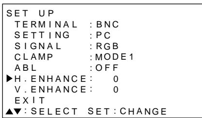
4 Press to adjust.
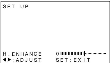
Pressing SET returns the display to the step 3 screen.
5 When the setup is finished, press MENU to exit the menu screen.
Note
H. ENHANCE or V. ENHANCE mode adjusting is only possible during PC signal input.
Make the adjustment for each input (INPUT3 and INPUT4).
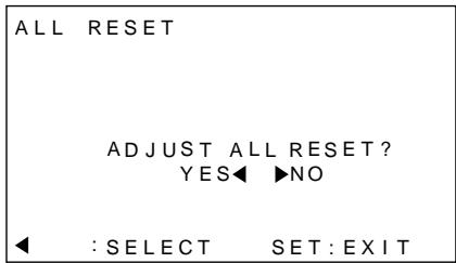
Resetting the unit to factory set defaults
1 Press MENU to display the menu screen.
The menu screen appears.
2 Press / to select ALL RESET, then press SET.

3 Press to select YES, then press SET.
All settings of the PICTURE and SCREEN modes are returned to the default settings (factory set defaults).
Cleaning
Regular cleaning will extend the life and performance of this unit. The recommended way to clean the display and related parts is described below.
Before cleaning, be sure to unplug the power cord from the power outlet.
Cleaning the display panel body and remote control
Do not under any circumstances use solvents such as benzine or thinner for cleaner. Use of such liquids may cause deterioration or peeling of paint from the display or remote control unit.
Wipe the display and remote control gently with a soft cloth. In the case of excessive dirt buildup, dampen a soft cloth with a diluted neutral cleaning detergent and after wringing the cloth thoroughly, wipe the component and then dry it with a dry soft cloth.
Cleaning the screen
After dusting, wipe the screen gently using the supplied cleaning cloth or a soft cloth. Do not use tissue or a rough cloth. As the surface of the screen is easily scratched, do not rub it or hit it with a hard object.
Cleaning the vents
As a general rule, use a vacuum cleaner about once a month to clean the vents on the rear panel of the display of dust buildup (set the vacuum cleaner to its weakest setting when doing this).
Using the unit without cleaning it of dust will cause the internal temperature to increase, resulting in possible breakdown or fire.

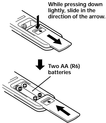
Inserting the batteries in the remote control unit
When handling the remote control unit
- Do not drop or shake the remote control.
- Do not use the remote control unit in a location subject to direct sunlight, heat radiation from a heater, or in a place subject to excessive humidity.
- When the remote control unit's batteries begin to wear out, the operable distance will gradually become shorter. When this occurs, replace all batteries with new ones as soon as possible.

CAUTION
- Insert batteries so that the plus (+) and minus (-) sides are aligned according to the markings in the battery case.
- Do not mix new batteries with used ones.
- The voltage of batteries may differ even if they are the same shape. Please do not mix different kinds of batteries together.
- When not using the remote control unit for a long period of time (1 month or more), remove the batteries from the remote control unit to prevent leaking of battery fluid. If battery liquid has leaked, thoroughly wipe the inside of the case until all liquid is removed, and then insert new batteries.
- Do not charge, short, disassemble or throw the provided batteries in a fire.
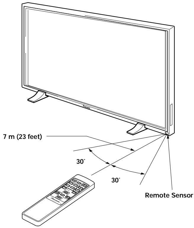
Operating range of the remote control unit
When operating the remote control unit, point it at the remote sensor (SR) located on the front panel of the main unit. The remote control unit is operable up to 23 feet (7 m) from the unit and within a 30 angle on each side of the sensor.
If you are having difficulty with operation of the remote control unit
- The remote control unit may not operate if there are objects placed between it and the display.
- Operational distance will gradually become shorter as the batteries begin to wear out, replace weak batteries with new ones as soon as possible.
- This unit discharges infrared rays from the screen. Placing a video deck or other component that is operated by an infrared remote control unit near this unit may hamper that component's reception of the remote control's signal, or prevent it from receiving the signal entirely. Should this occur, move the component to a position further away from this unit.
- Depending on the installation surroundings, this unit's remote control unit may be influenced by the infrared rays discharged from the plasma display, hampering reception of its rays or limiting its operational distance. The strength of infrared rays discharged from the screen will differ according to the picture displayed.
Troubleshooting
What may at first seem to be an malfunction, may be remedied with a quick check. Please check to see if a warning is displayed on the screen. If displayed, refer to page 24 and check the mode. If there is no display check to see if the problem is listed below. The problem may also be caused by something other than this unit so please also check the other components being used such as a video deck. If the problem can still not be solved please consult the dealer where this unit was purchased.
General Problems
| Problem | Possible Solution |
| • No power | • Is the power cord disconnected? (page 12) • Has the MAIN POWER switch been switched on? (page 7) |
| • Unit cannot be operated. | • External influences such as lightning, static electricity, etc., may cause improper operation. In this case, operate the unit after first turning the main power on/off, or unplugging the power cord and re-plugging it in after 1 to 2 minutes. |
| • Remote control does not operate. | • Are batteries inserted with polarity (+,-) correctly aligned? (page 22) • Are batteries worn out? (Replace with new batteries). • Is the plug inserted in the CONTROL IN terminal? Because reception of the remote control's signal will not be possible if the plug is inserted, please check connections (page 11). |
| • Picture is cut off. | • Is the selected screen size correct? Switch to another screen size (page 16). • Are SCREEN mode adjustments such as picture size made correctly? (page 19). |
| • Strange color, light color, or dark, or color misalignment | • Adjust the picture tone (page 18). • Is the room too bright? The picture may look dark in a room that is too bright. |
| • Power is suddenly turned off. | • The unit's internal temperature has increased. (Air vents are blocked.) Remove any objects blocking vent or clean (page 22). • Is the POWER SAVE mode set to “MODE1” or “MODE2”? (page 17) |
| • No picture | • Are all connections correct? (page 10) • Has setup been done correctly after connection? (page 13) • Is the correct input selected? (page 14) • Is a non-compatible signal being input? (page 26) • Is picture adjustment correct? (page 18) |
Problems commonly mistaken as breakdown
| Problem | Possible Solution |
| ·The screen is displayed in a small size. | ·Check the input signal compatibility chart (page 26). ·Is the correct screen size selected? (page 16) |
| ·Letter breakup on screen. | ·Adjust using “SCREEN” mode on the menu screen (page 19). If there is still no improvement, this unit may be limiting the displayable range. Check the personal computer input signal compatibility chart (page 26). |
| ·A sharp sound is sometimes heard from the cabinet. | ·Expansion/contraction caused by surrounding temperature change may result in sound being heard from the cabinet. This is not a malfunction. |
| ·Bright portions of image appear to be losing intensity. | ·When the input signal's level is too high, the bright portions may appear to be losing their intensity. Increase the adjustment level of the contrast and check the picture (page 18). |
| ·Speckles or noise appears on screen. | ·May be caused by radio wave interference from appliances with motors such as hair dryers, electric vacuum cleaners, electric power drills, ignition systems of cars, motorcycles etc., switch devices such as thermostats etc., neon signs or electrical discharge from power lines etc.. |
| ·Stripes appear on the screen. | ·May be caused by radio wave mingling from TV station, FM station, amateur radios, public radios (simplified radios) etc., or a nearby personal computer, TV, or video/audio component. ·A strong electromagnetic field may cause picture distortion and similar problems. |
| ·Operation is not possible. | ·External influences such as lightning strike, static electricity etc., may cause improper operation. In this case, operate the unit after first turning the main power ON/OFF, or unplugging the power cord and re-plugging it in after 1 to 2 minutes. |
| ·Sound is heard from inside the unit. | ·Sound of fan revolving. This is not a malfunction. |
Although this unit incorporates high precision technology in its design, please understand that there may be extremely slight pixel breakup, or light emission fault.
Note
In order to protect this unit's panels and circuitry, the revolving speed of the interval fan will be automatically increased in order to cool the inside of the unit when the surrounding temperature exceeds 40^ . (The sound of the fan will become louder at this time). Please operate this unit in a location with a surrounding temperature under 40^ .
Additional cautions
- If the power is automatically turned off during operation of this unit, the following reasons may be the cause.
① Is the POWER SAVE mode set to "MODE1" or "MODE2"? (page 17)
(2) The surrounding temperature has risen above 40^ C . Please operate this unit in a location with a surrounding temperature under 40^ C .
(3) The vents are blocked or the internal temperature has risen abnormally due to abnormal heat generation of internal parts etc..
If the power is automatically turned off for a reason other than the above reasons, there could be a malfunction. In this case, unplug the power cord from the power outlet and request repair from your nearest sales outlet.
- The plasma display panel of this unit is very bright and viewing it a close distance will cause eye strain. We recommend that you view the screen from a suitable distance (3 to 6m).
About the plasma panel's protection function
The brightness of this display will deteriorate slightly when an image with little movement such as a photograph or computer image is continuously displayed. This is caused by the plasma panel's protection function which detects images with slight movement and automatically adjusts brightness to protect the display, and is not a malfunction. This function starts approximately 5 minutes after the power has been turned on or after input has been switched.
About the self diagnosis mode
Messages appear on the bottom of this unit's screen to indicate operation or connection faults. After message confirmation, check the condition of the unit.
| If this message appears | Please do this |
| OUT OF RANGE or PLEASE CHANGE RESOLUTION OR REFRESH RATE | A incompatible signal is being input. Check the PC input signal compatibility chart on page 26 and change the output signal setting on the computer side. |
| THERMAL WARNING! PLEASE SHUT DOWN | Turn off main power (page 14). Has the room temperature exceeded 40 °C? Reduce the room temperature. If the unit's vents are blocked, unblock them. |
CAUTION
Panel sticking and after-image lag
-
Displaying the same images such as still images for a long time may cause after-image lagging. This may occur in the following two cases.
-
After-image lagging due to remaining electrical load When image patterns with very high peak luminance are displayed for more than 1 minute, after-image lagging may occur due to the remaining electric load. The after-images remaining on the screen will disappear when moving images are displayed. The time for the after-images to disappear depends on the luminance of the still images and the time they had been displayed.
- After-image lagging due to sticking
Avoid displaying the same images continuously over a long period of time with the Plasma Display. When images of the same pattern are displayed continuously for several hours or displayed for a short period of time every day, after-images may remain on the screen due to the sticking of the fluorescent materials. In this case, these images may decrease if moving images are displayed after them, but basically they will not disappear.
Specifications
General
Light emission panel 50 inch plasma display panel Number of pixels 1280 x 768
Power supply AC 100 - 240 V, 50/60 Hz
Rated current 5.4 - 2.2 A
Standby power consumption 0.6 W
External dimensions. 1218 (W) x 714 (H) x 98 (D) mm (when using display stand)
(including display stand) 41.0 kg
Operating temperature range 0 to 40^
Operating atmospheric pressure range 0.8 to 1.1 atmospheric pressure
Input/output
Video
INPUT 3
Input
BNC jack (x5)
RGB signal (G ON SYNC compatible)
RGB ... 0.7 Vp-p/75 Ω/no sync.
HD/CS, VD ... TTL level
/positive and negative polarity/
75 Ω or 2.2 kΩ
(impedance switch)
G ON SYNC ...
1 Vp-p/75 Ω/negative sync.
INPUT 4
Input
Mini D-sub 15 pin (socket connector)
RGB signal (G ON SYNC compatible)
RGB ... 0.7 Vp-p/75 Ω/no sync.
HD/CS, VD ... TTL level
/positive and negative polarity /2.2k
G ON SYNC
... 1 Vp-p/75 Ω/negative sync.
*Compatible with Microsoft's Plug & Play (VESA DDC1/2B)
Output
Mini D-sub 15 pin (socket connector)
75 Ω/with buffer
Audio
Input
AUDIO INPUT (for INPUT3)
Pin jack (x2)
L/R ... 500mVrms/more than 10 kΩ
AUDIO INPUT (for INPUT4)
Stereo mini jack
L/R ... 500mVrms/more than 10 kΩ
Output
AUDIO OUTPUT
Stereo mini jack
L/R ... 500mVrms (max)/less than 5 kΩ
SPEAKER
L/R ... 8 - 16 Ω/2W +2W (at 8 Ω)
Control
CONTROL IN/OUT ... monaural mini jack (x2)
Accessories
Remote control unit 1
Remote control unit case 1
AA (R6/UM-3) batteries 2
Cleaning cloth 1
Speed clamp 2
Bead band 2
Operating Instructions 1
Display stand 2
Washer (large) 2
Washer (small) 2
Hex hole bolt (M8X40) 2
- Due to improvements, specifications and design are subject to change without notice.
Supplement 1
PC signal compatibilty table (INPUT3, INPUT4)
| Resolution(Dot x Line) | Verticalfrequency | Horizontalfrequency | Screen size (Dot x line) | Remarks | |||
| ORIGINAL | 4.3 NORMAL | FULL | ZOOM | ||||
| 640x400 | 56.4Hz | 24.8kHz | ○1280x768 | NEC PC-9800 | |||
| 70.1Hz | 31.5kHz | ↑ | NEC PC-9800 | ||||
| 640x480 | 60Hz | 31.5kHz | ◎640x480 | ○1024x768 | ○1280x768 | (852x480)(864x480) | |
| 66.7Hz | 35.0kHz | ↑ | ↑ | ↑ | Apple Macintosh 13" | ||
| 72Hz | 37.9kHz | ↑ | ↑ | ↑ | |||
| 75Hz | 37.5kHz | ↑ | ↑ | ↑ | |||
| 85Hz | 43.3kHz | ↑ | ↑ | ↑ | |||
| 800 x600 | 56Hz | 35.2kHz | ◎800x600 | ○1024x768 | ○1280x768 | ||
| 60Hz | 37.9kHz | ↑ | ↑ | ↑ | (1072x600) | ||
| 72Hz | 48.1kHz | ↑ | ↑ | ↑ | |||
| 75Hz | 46.9kHz | ↑ | ↑ | ↑ | |||
| 85Hz | 53.7kHz | ◎800x600 | ○1024x720 | ○1280x720 | |||
| 832x624 | 74.6Hz | 49.7kHz | ◎832x624 | ○1024x748 | ○1280x748 | Apple Macintosh 16" | |
| 1024x768 | 43HzInterlace | 35.5kHz | △1024x768 | △1280x768 | |||
| 60Hz | 48.4kHz | ◎1024x768 | ○1280x768 | (1376x768) | |||
| 70Hz | 56.5kHz | ↑ | ↑ | ||||
| 75Hz(74.9Hz) | 60.0kHz(60.2kHz) | ↑ | ↑ | () indicates Apple Macintosh 19" | |||
| 85Hz | 68.7kHz | ↑ | ↑ | ||||
| 1152x864 | 60Hz | 53.7kHz | △1024x768 | △1280x768 | |||
| 72Hz | 64.9kHz | ↑ | ↑ | ||||
| 75Hz | 67.7kHz | ↑ | ↑ | ||||
| 1152x870 | 75.1Hz | 68.7kHz | △1024x768 | △1280x768 | Apple Macintosh 21" | ||
| 1152x900 | 66.0Hz | 61.8kHz | △1024x768 | △1280x768 | Sun Microsystems LO | ||
| 76.0Hz | 71.7kHz | ↑ | ↑ | Sun Microsystems HI | |||
| 1280x768 | 56Hz | 45.1kHz | ◎1280x768 | ||||
| 1280x960 | 60Hz | 60.0kHz | △1024x768 | △1280x768 | |||
| 1280x1024 | 43HzInterlace | 46.4kHz | △1280x768 | ||||
| 60Hz | 64.0kHz | △960x768 | △1280x768 | ◎1280x768 | |||
| 75Hz | 80.0kHz | △960x768 | (1600x1024) | ||||
| 85Hz | 91.1kHz | ↑ | |||||
| 1600 x 1200 | 60Hz | 75.0kHz | △1024x768 | ||||
| 65Hz | 81.3kHz | ↑ | |||||
| 70Hz | 87.5kHz | ↑ | |||||
: Optimal picture. Adjustment of picture position, frequency, phase etc., may be necessary.
: Picture will be enlarged but some fine detail will be hard to see.
: Simple reproduction. Fine detail will not be reproduced. Screen size will be displayed as " (TYPE)" .
Not available.
Supplement 2
Signal assignment of INPUT 4 (Mini D-sub 15 pin socket connector)
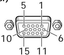
| Pin No. | Input | Output |
| 1 | R | ← |
| 2 | G | ← |
| 3 | B | ← |
| 4 | NC (No connection) | ← |
| 5 | GND | NC (No connection) |
| 6 | GND | ← |
| 7 | GND | ← |
| 8 | GND | ← |
| 9 | DDC + 5V | NC (No connection) |
| 10 | GND | ← |
| 11 | NC (no connection) | ← |
| 12 | DDC SDA | NC (No connection) |
| 13 | HD or H/V SYNC | ← |
| 14 | VD | ← |
| 15 | DDC SCL | NC (No connection) |
Explanation of Terms
Aspect ratio
The TV screen's width to height ratio is referred to as its aspect ratio. The aspect ratio on standard TVs is 4:3 and on wide TVs or High Definition TVs it is 16:9.
G ON SYNC
This indicates a video signal in the form of a synchronization signal added to the G (GREEN) signal of the R.G.B signal.
VGA
VGA is short for "Video Graphics Array".
Generally this indicates a 640 dot x 480 line resolution.
XGA
General term for "eXtended Graphics Array".
Generally this indicates a 1024 dot x 768 line resolution.
Macintosh is a registered trademark of Apple Computer, Inc.
Microsoft is a registered trademark of Microsoft Corporation.
PC-9800 is a trademark of NEC Corporation.
NEC is a trademark of NEC Corporation.
VESA is a registered trademark of Video Electronics
Standards Association.
Sun Microsystems is a registered trademarks of Sun
Microsystems, Inc.
IMPORTANT

Installation et raccordements 8
(3) COMBINATION IN/OUT
⑦ AUDIO INPUT (Prises Cinch)
Standards Association.
The lightning flash with arrowhead symbol, within an equilateral triangle, is intended to alert the user to the presence of uninsulated "dangerous voltage" within the product's enclosure that may be of sufficient magnitude to constitute a risk of electric shock to persons.
CAUTION
RISK OF ELECTRIC SHOCK
DO NOT OPEN
CAUTION:
TO PREVENT THE RISK OF ELECTRIC SHOCK,DO NOT REMOVE COVER (OR BACK).NO USER-SERVICEABLE PARTS INSIDE.REFER SERVICING TO QUALIFIED SERVICE PERSONNEL.

The exclamation point within an equilateral triangle is intended to alert the user to the presence of important operating and maintenance (servicing) instructions in the literature accompanying the appliance.
MAIN MENU
PICTURE
SCREEN
ALL RESET
POWER SAVE
▶SET UP
MENU:MENU OFF
▲▼ :SELECT SET:NEXT
The lightning flash with arrowhead symbol, within an equilateral triangle, is intended to alert the user to the presence of uninsulated "dangerous voltage" within the product's enclosure that may be of sufficient magnitude to constitute a risk of electric shock to persons.
CAUTION
RISK OF ELECTRIC SHOCK
DO NOT OPEN
CAUTION:
TO PREVENT THE RISK OF ELECTRIC SHOCK,DO NOT REMOVE COVER (OR BACK).NO USER-SERVICEABLE PARTS INSIDE.REFER SERVICING TO QUALIFIED SERVICE PERSONNEL.

The exclamation point within an equilateral triangle is intended to alert the user to the presence of important operating and maintenance (servicing) instructions in the literature accompanying the appliance.
(secondarynormeEN60320SheetC13)
MAIN MENU
PICTURE
SCREEN
ALL RESET
POWER SAVE
▶SET UP
MENU:MENU OFF
▲▼ :SELECT SET:NEXT
Batterie AA (R6/UM-3) 2
Panno pulente 1
Electronics Standards Association.
Sun Microsystems, Inc.
IMPORTANT

The lightning flash with arrowhead symbol, within an equilateral triangle, is intended to alert the user to the presence of uninsulated "dangerous voltage" within the product's enclosure that may be of sufficient magnitude to constitute a risk of electric shock to persons.
CAUTION
RISK OF ELECTRIC SHOCK
DO NOT OPEN
CAUTION:
TO PREVENT THE RISK OF ELECTRIC SHOCK,DO NOT REMOVE COVER (OR BACK).NO USER-SERVICEABLE PARTS INSIDE.REFER SERVICING TO QUALIFIED SERVICE PERSONNEL.

The exclamation point within an equilateral triangle is intended to alert the user to the presence of important operating and maintenance (servicing) instructions in the literature accompanying the appliance.
Installation of the unit 8
⑥ Display-standardx2

(3) COMBINATION IN/OUT
SLUIT NIETS AAN OP DEZE AANSLUITINGEN.
Installation of the unit
G ON SYNC setup (CLAMP)
MAIN MENU
PICTURE
SCREEN
ALL RESET
POWER SAVE
▶SET UP
MENU:MENU OFF
▲▼ :SELECT SET:NEXT
3 Druk op / en kies ABL.
SETUP TERMINAL:BNC SETTING:PC SIGNAL:RGB CLAMP:MODE1 ▲ABL :OFF H. ENHANCE: 0 V. ENHANCE: 0 EXIT :SELECT SET:CHANG
HD/CASSETTE, VD ... TTL niveau/
...1 Vp-p/75 Ohm/negative sync.
INPUT4
(Ingang)
HD/CASSETTE, VD ... TTL niveau/
Electronics Standards Association.
The lightning flash with arrowhead symbol, within an equilateral triangle, is intended to alert the user to the presence of uninsulated "dangerous voltage" within the product's enclosure that may be of sufficient magnitude to constitute a risk of electric shock to persons.
CAUTION
RISK OF ELECTRIC SHOCK
DO NOT OPEN
CAUTION:
TO PREVENT THE RISK OF ELECTRIC SHOCK,DO NOT REMOVE COVER (OR BACK).NO USER-SERVICEABLE PARTS INSIDE.REFER SERVICING TO QUALIFIED SERVICE PERSONNEL.

The exclamation point within an equilateral triangle is intended to alert the user to the presence of important operating and maintenance (servicing) instructions in the literature accompanying the appliance.
Adjusting the display image 19
(3) COMBINATION IN/OUT
NO HAGA NINGUNA CONEXION A ESTOS TERMINALES.
MAIN MENU
PICTURE
SCREEN
ALL RESET
POWER SAVE
▶SET UP
MENU:MENU OFF
▲▼ :SELECT SET:NEXT
3 Pulse / para seleccionar ABL.
SETUP TERMINAL:BNC SETTING:PC SIGNAL:RGB CLAMP:MODE1 ▲ABL :OFF H. ENHANCE: 0 V. ENHANCE: 0 EXIT ▲▼:SELECT SET:CHANGE
4 Pulse SET paraponer el modo en "ON".
Pilas AA (R6/UM-3) 2
Paño de limpieza 1
Abrazadera rapiida. 2
Banda deCNTas 2
France : tapez 36 15 PIONEER
Published by Pioneer Corporation
Copyright © 1999 Pioneer Corporation.
All rights reserved.
Home Entertainment Company (Consumer products)
PIONEER CORPORATION 4-1, Meguro 1-Chome, Meguro-ku, Tokyo 153-8654, Japan
PIONEER ELECTRONIC [EUROPE] N.V. Haven 1087, Keetberglaan 1 B-9120 Melsele, Belgium, TEL: 32-3-570-0511
PIONEER ELECTRONICS ASIACENTRE PTE.LTD. 253 Alexandra Road #04-01, Singapore, 159936, TEL: 65-472-1111
PIONEER GULF FZE P.O.BOX 61226, Jebel Ali, Dubai, United Arab Emirates, TEL:(971)4-815756
Business Systems Company (Products for business use)
PIONEER CORPORATION 4-1, Meguro 1-Chome, Meguro-ku, Tokyo 153-8654, Japan
PIONEER ELECTRONIC [EUROPE] N.V. MULTIMEDIA DIVISION Pioneer House Hollybush Hill, Stoke Poges, Slough SL2 4QP, U.K., TEL:44-1753-789-789
PIONEER ELECTRONICS AUSTRALIA PTY.LTD. 178-184 Boundary Road, Braeside, Victoria 3195, Australia, TEL:61-39-586-6300
PIONEER ELECTRONICS (CHINA) LTD. Room 1704-06,17/F World Trade Centre, 280 Gloucester Rd Causeway Bay, H.K., TEL:852-2848-6488
PIONEER ELECTRONICS ASIACENTRE PTE.LTD. 253 Alexandra Road, #04-01, Singapore, 159936, TEL:65-472-1111
PIONEER GULF FZE P.O.BOX 61226, Jebel Ali, Dubai, United Arab Emirates, TEL:(971)4-815756