
ST 500 - Electric saw AEG-ELECTROLUX - Free user manual and instructions
Find the device manual for free ST 500 AEG-ELECTROLUX in PDF.
| Product type | Electric jigsaw |
| Brand | AEG-ELECTROLUX |
| Model | ST 500 |
| Max. cutting depth (softwood) | 65 mm |
| Max. cutting depth (steel) | 10 mm |
| Power consumption | 500 W |
| No-load stroke rate | 450-3000 min⁻¹ |
| Stroke height | 19 mm |
| Bevel cut up to | 45° |
| Supply voltage | 230 V ~ 50 Hz |
| Double insulation | Yes (class II) |
| Sound level (no-load) | 82 dB(A) |
| Vibration level | 3 m/s² |
| Application | Wood, synthetic material, metal |
| Cut types | Straight, bevel, curve, plunge |
| Base plate adjustment | Tiltable (15°, 30°, 45°) |
| Chip extraction | Yes (30 mm diameter) |
| Maintenance | Annual brush check recommended |
| Optional accessories | Splinter guard, parallel stop, circular guide, synthetic base plate |
Frequently Asked Questions - ST 500 AEG-ELECTROLUX
User questions about ST 500 AEG-ELECTROLUX
0 question about this device. Answer the ones you know or ask your own.
Ask a new question about this device
Download the instructions for your Electric saw in PDF format for free! Find your manual ST 500 - AEG-ELECTROLUX and take your electronic device back in hand. On this page are published all the documents necessary for the use of your device. ST 500 by AEG-ELECTROLUX.
USER MANUAL ST 500 AEG-ELECTROLUX
ST 500 STE 500 STEP 500
natural_image
Line drawing of a manual push-button electric shaver with control panel and lever (no text or symbols)GB Instructions for use
Please read and save these instructions.
D Gebrauchsanleitung Bitte lesen und aufbewahren.
F Instruction d'utilisation Prière de lire et de conserver.
I Istruzioni d'uso
Si prega di leggere le istruzioni e
di conservarle.
E Instrucciones de uso
Lea y conserve estas
instrucciones por favor.
P Instruções de serviço
Por favor leia e conserve em seu poder.
NL Gebruiksaanwijzing
Lees en let goed op deze adviezen.
DK Brugsanvisning
Vær venlight at læse og opbevare.
s Bruksanvisning
Var god läs och tag tillvara dessa instruktioner.
SF Käyttöohje
Lue ja säilytö
TR Kullanım kılavuzu
Lütfen okuyun ve saklayin
RUS Инструкция по использованию
Пожалуйста, прочтите и сохраните настоящую инструкцию
RC 使用說明書
請詳細閱讀並妥善保存
| Introduction | You demand the best and buy quality – quality provided by Atlas Copco.We have built for you a reliable and lasting tool. Working effectively and without endangering your health is only possible if these instructions for use are being read carefully before first using this tool. We want to satisfy our customers and would like you to buy again AEG Electric Power Tools from Atlas Copco. | |||||
| Technical Data | ST 500 | STE 500 | STEP 500 | |||
| Cutting depth max. in:Soft– wood . . . . . . . . . . . . . . . . . . . . . . . . . . . . . . . . . . . . . . . . . . . . . . . . . . . . . . . . . . . . . . . . . . . . . . . . . . . . . . . . . . . . . . . . . . . . . . . . . . . . ..Hard–wood . . . . . . . . . . . . . . . . . . . . . . . . . . . . . . . . . . . . . . . . . . . . . . . . . . . . . . . . . . . . . . . . . . . . . . . . . . . . . . . . . . . . . . . . . . . . . . . . . . . Steel . . . . . . . . . . . . . . . . . . . . . . . . . . . . . . . . . . . . . . . . . . . . . . . . . . . . . . . . . . . . . . . . . . . . . . . . . . . . . . . . . . . . . . . . . . . . . . . . . . . Aluminium . . . . . . . . . . . . . . . . . . . . . . . . . . . . . . . . . . . . . . . . . . . . . . . . . . . Nominal power . . . . . . . . . . . . . . . . . . . . . . . . . . . . . . . . . . . . . . . . . Weight . . . . . . . . . . . . . . . . . . . . . . . . . . . . . . . . . . . . . . . Stroke rate under no-load . . . . . . . . . . . . . . . . . . . . . . . . Lengths of stroke . . . . . . . . . . . . . . . . . . . . . . . . . . Bevel cuts up to . . . . . . . . . . . . . . . . . . . . . . . . . . . . . . . . . . . . . . . . . . . . . . . . . . . . . . . . . . . . . . . . . . . . . . . . . . . . . . . . . . . . . . . . . . . . . . . . . . . | ||||||
| Advice for your safety | ■ Please pay attention to the safety instructions in the attached leaflet!■ Dust that arises when working on material containing asbestos or stonework containing crystalline silicic acid is harmful to the health. Please follow accident prevention regulations.■ Appliances used at many different locations including open air must be connected via a current surge preventing switch.■ Always use the protective shields on the machine.■ Always disconnect the plug from the socket before carrying out any work on the machine.■ Always wear goggles when using the machine. It is recommended to wear gloves, sturdy non slipping shoes and apron.■ Sawdust and splinters must not be removed while the machine is running.■ Do not pierce the motor housing as this could damage the double insulation (use adhesives).■ Keep mains lead clear from working range of the machine. Always lead the cable away behind you.■ Only plug-in when machine is switched off.■ Dust that arises when working on wood or using the tool on industrial material can be dangerous to health. In this case connect the tool to a suitable suction device.■ Do not use cracked or distorted saw blades. | |||||
| Measured sound value | Typically the A-weighted sound pressure level of the tool is 82 dB (A).The noise level when working can exceed 85 dB (A). Wear ear protectors! Measured values determined according to EN 50 144. | |||||
| Measured vibration value | Typically the weighted acceleration is 3 m/s^2 .Measured values determined according to EN 50 144. | |||||
| Use | This jig saw can cut wood, plastic and metal; it can cut straight lines, bevels, curves, and internal cut-outs.Do not use this product in another way as stated for normal use. | |||||
| Mains connection | Connect only to a single-phase AC current supply and only to the mains voltage specified on the rating plate. Connection to sockets without earth protection is possible as the appliance features protective insulation to DIN 57 740/ VDE 0740 and CEE 20. Radio suppression complies with the European standard EN 55014. When fitting the plug, make sure that the brown (live) wire of this appliance is connected to the plug terminal marked L or coloured red, and the blue (neutral) wire of this appliance is connected to the plug terminal marked N or coloured black. Under no circumstances must the wires of this appliance be connected to the earth terminal of the plug marked either E, with the earth symbol or coloured green or green/yellow. | |||||
| ENGLISH | 1 | ST 500, STE 500, STEP 500 | ||||
Brief description
The vibration damper permits quieter running by means of a counterweight on the plunger.
Modifications: Text, diagrams and data are correct at the time of printing. In the interest of continuous improvement of our products, technical specifications are subject to alteration without prior notice.
| Inserting the saw-blade | ⚠️ | Always disconnect the plug from the socket before carrying out any work on the machine. | |
| 1. | Slide the transparent cover downwards, then the clamping screw is more accessible. | ||
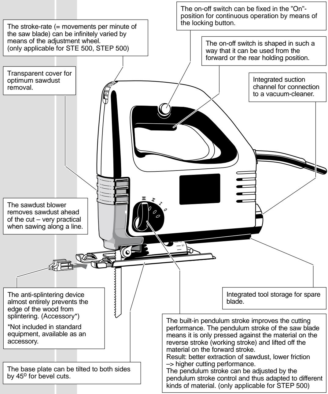
| 2. | Loosen the clamping screw about 2 revolutions by means of the hexagonal allen key (fitted into the base plate). 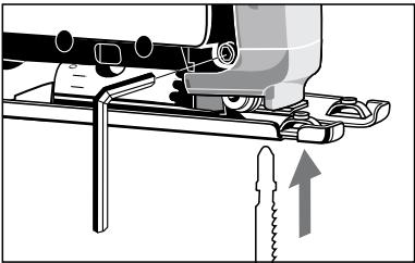 | ||
| 3. | Fit the saw blade into the groove of the support roller and push it firmly into the plunger as far as it will go; the lug of the saw blade must contact the end of the plunger (see illustration). 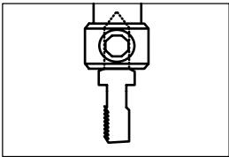 | ||
| 4. | Retighten the clamping screw. | ||
| 5. | Check that the saw blade is sitting firmly (wear protective gloves!). | ||
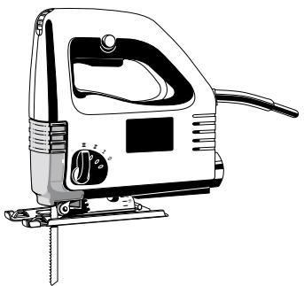
| Adjusting the base plate | The base plate can be tilted or moved backward or forward.Setting an angle ➔ For angle cuts and bevels.Loosen the fixing screw, pull the base plate out of the mounting, set it at the required angle (15°, 30°, 45°), push it back into the mounting and tighten the fixing screw again. Angles other than 45° can be set by not pushing the base plate back into the mounting.The angle can be read off the scale.For very exact angle cuts it is recommended to make a test cut.Moving the base plate ➔ For plunge cuts or cuts in corners.Loosen the fixing screw, push the base plate to the rear and tighten the fixing screw again. The base plate in this position is fixed at the 0° setting.Moving back ➔ For cutting a hole with a short saw blade and sawing near the edge.Take the fixing screw out, push the base plate to the rear and screw the fixing screw tightly into the rear hole.In this position the base plate can also be off-set in longitudinal direction. | ||
| Sawdust removal | ⚠️ | Only operate the machine with suitable sawdust removal.The integrated suction channel has the standardized internal diameter of 30 mm. Use the suction hose (Id. No. 4932 3304 12) from our range of accessories to connect it to a household vacuum cleaner or to an wet-and-dry vacuum cleaner. 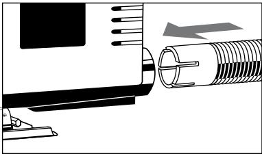 | |
| ENGLISH | 3 | ST 500, STE 500, STEP 500 | |
| 1. Push in and turn the suction hose into the suction channel until it fits firmly. | 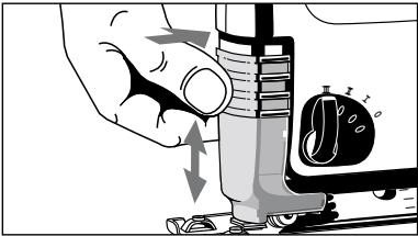 | ||
| 2. Push the transparent cover downwards to ensure optimum sawdust removal. | |||
| Anti-splintering device (Accessory*) | The anti-splintering device almost entirely prevents the edge of the wood from splintering.Place the anti-splintering device as shown in the illustration with the smooth side downwards and flush with the base plate (this is only possible with the base plate in the forward position).*Not included in standard equipment, available as an accessory. | 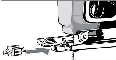 | |
| Adjusting the stroke rate(only applicable for STE 500 STEP 500) | The stroke-rate (= movements per minute of the saw blade) can be infinitely varied by means of the adjustment wheel.The letters A to G are printed on the speed control, meaning:A = lowest stroke rateG = highest stroke rateThe stroke rate appropriate to the material being worked on can be taken from the following table, and the corresponding letter shown on the setting wheel. | 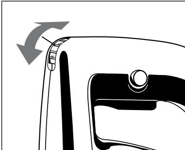 | |
| Material | Stroke rate | ||
| Wood | G | ||
| Steel | D-E | ||
| Aluminium | D-E | ||
| Rubber | A-C | ||
| On-/off switch | Intermittent useSwitching on: Press On-/off switchSwitching off: Release On-/off switchContinuous useSwitching on: Press the On-/off switch and then the locking button, after that release on-off switch.Switching off: Press the On-/off switch and then release. |  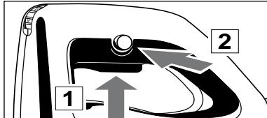 | |
| Adjusting the pendulum stroke(only applicable for STEP 500) | By adjusting the pendulum action the cutting depth of the saw blade teeth is increased or decreased. As a rule of thumb:Soft material Large pendulum strokeHard material Small or no pendulum strokeClean cut surface No pendulum stroke | ||
| ENGLISH | 4[YG TG] | ST 500, STE 500, STEP 500The appropriate degree of pendulum effect can be taken from the following chart and compared with the marking at the pendulum stroke lever. | |
| Material | Degree of swing action | ||
| Wood | I - III | ||
| Plastic | I | ||
| Aluminium | 0 - I | ||
| Steel | 0 | ||
| Ceramics | 0 | ||
| Rubber | 0 | ||
| The stroke rate shown in the chart is only a suggestion for your general guidance! | |||
| The stroke rate can be set on the stroke rate control even while the motor is running. | |||
| Advice for operation | 1. | Set the stroke and pendulum stroke according to the material to be cut. | |
| 2. | Position the machine with the front part of the base plate on the material, and switch on. | ||
| 3. | Press the machine downwards onto the material and guide it along the cutting line. | ||
| Hints |  | Do not press down too hard on the piece you are cutting. Light pressure on the saw blade is sufficient to achieve the optimum rate of sawing.When cutting along a score line, use the marking on the anti-splintering device as an optical guide.To obtain a perfectly straight cut, clamp a strip of wood as a guide along the material or use the parallel guide (accessory).For cutting at an angle, or cutting a bevel, adjust the base plate.For sawing close to the edge, set the base plate at its rearmost position. | |
| Sawing sheet metal | To avoid vibration, clamp metal sheets onto a wooden base.To saw metal, use cooling agents along the cutting line (oil, white spirit). | ||
| Plunge cuts | Plunge cuts without pre-drilling a hole are possible with soft materials (wood, light building materials for walls). Harder materials (metals) must first be drilled with a hole corresponding to the size of the saw blade.Move the base plate to the rearmost setting in order to obtain the best possible cutting angle for starting the cut.(see section "Adjusting the base plate") | ||
| 1. | Set the pendulum stroke at the pendulum stroke control to "0". | ||
| 2. | Without switching the machine on, place it with the front edge of the base plate on the cutting point. | ||
| 3. | Switch the machine on and carefully lower the saw blade already running into the material. | ||
| ENGLISH | 5 | ST 500, STE 500, STEP 500 | |
EC-DECLARATION OF CONFORMITY
We declare under our sole responsibility that this product is in conformity with the following standards or standardized documents.
EN 50144, EN 55014-1, EN 55014-2, EN 61000-3-2, EN 61000-3-3, in accordance with the regulations 98/37/EC, 73/23/EEC, 89/336/EEC
DEUTSCH
DÉCLARATION "CE" DE CONFORMITÉ
Manager Product Marketing and Development


Atlas Copco
Copyright 2000
Atlas Copco Electric Tools GmbH
P.O. Box 320
D-71361 Winnenden Germany
www.atlascopco.de
Brand : AEG-ELECTROLUX
Model : ST 500
Category : Electric saw