
FDPP 201450-E - Saw Fieldmann - Free user manual and instructions
Find the device manual for free FDPP 201450-E Fieldmann in PDF.


| Type | Compound Mitre Saw |
| Brand | Fieldmann |
| Model | FDPP 201450-E |
| Rated Voltage / Frequency | 220-240 V ~, 50 Hz |
| Rated Power Input | 1450 W (S1) |
| No-Load Speed | 5000 min⁻¹ |
| Protection Class | II (Double Insulation) |
| Weight | approx. 8.5 kg |
| Dimensions (approx.) | 460 x 360 x 355 mm |
| Saw Blade Outer Diameter | 210 mm |
| Saw Blade Bore Diameter | 30 mm |
| Blade Thickness | 2.8 mm |
| Number of Teeth | 40 |
| Max Blade Speed | 7000 min⁻¹ |
| Cutting Capacity (0°/0°) | 120 x 60 mm |
| Cutting Capacity (0°/45°) | 120 x 34 mm |
| Cutting Capacity (45°/0°) | 85 x 60 mm |
| Cutting Capacity (45°/45°) | 85 x 34 mm |
| Mitre Range | -45° to +45° |
| Bevel Range | 0° to 45° (Left) |
| Sound Power Level (LWA) | 109.86 dB(A) (KWA=3.0 dB(A)) |
| Sound Pressure Level (LpA) | 96.86 dB(A) (KpA=3.0 dB(A)) |
| Included Accessories | Hex keys (4 mm & 6 mm), screw clamp, support assemblies, chip collection bag, transport handle |
Frequently Asked Questions - FDPP 201450-E Fieldmann
User questions about FDPP 201450-E Fieldmann
0 question about this device. Answer the ones you know or ask your own.
Ask a new question about this device
Download the instructions for your Saw in PDF format for free! Find your manual FDPP 201450-E - Fieldmann and take your electronic device back in hand. On this page are published all the documents necessary for the use of your device. FDPP 201450-E by Fieldmann.
USER MANUAL FDPP 201450-E Fieldmann
natural_image
Abstract black-and-white spiral pattern with no text or symbolsFIELDMANN®
Home & Garden Performance

natural_image
Green and black mechanical tool with a measuring scale, no visible text or symbols on the tool itself.FDPP 201450-E
English 5-38
Čeština....39-72
Slovenčina 73-106
Magyarul 107–140
Polski 141-176

Compound Mitre Saw
USER'S MANUAL
Thank you for your purchase of the compound mitre saw. For your personal safety, read and understand the Instruction Manual before using. Keep the Instruction Manual in a safe place for future reference.
TABLE OF CONTENTS
- GENERAL SAFETY INSTRUCTIONS ...... 6
- SYMBOLS....10
- GENERAL DESCRIPTION....12
- UNPACKING 13
- ASSEMBLY 14
- INTENDED USE AND GENERAL OPERATION 17
- MAINTENANCE 31
- STORAGE....34
- TROUBLESHOOTING....35
- DECLARATION OF CONFORMITY....36
- TECHNICAL SPECIFICATIONS....37
- DISPOSAL....38
1. GENERAL SAFETY INSTRUCTIONS
⚠ WARNING! Carefully read the instruction manual before use.
Important safety warnings
* Unpack the product carefully and be sure not to throw away any part of the package before having found all components of the product.
- Keep the product in a dry place out of reach of children.
Read all cautions and instructions. The failure to adhere to warning cautions and instructions may result in an accident, fire and/or a serious injury.
Packaging
The product is placed in a package preventing damage during transport. This package is a raw material therefore it can be handed-over for recycling.
Instructions for use
Before beginning to work with the machine, read the following safety rules and instructions for use. Familiarize with operating elements and the proper use of the device. Keep the manual in a safe place for future reference. We recommend keeping the original package including the inner packaging materials, cash voucher and guarantee card for a period of warranty at minimum. For a case of transportation, pack the machine into the original box from the manufacturer, thus ensuring a maximum protection of the product during a possible transport (e.g. moving or sending into a service station).

Note: If you hand the machine over to next persons, hand it over together with the manual. Adherence to the attached instructions for use is a precondition for the proper use of the machine. The operation manual includes also instructions for operation, maintenance and repairs.
The manufacturer does not take any responsibility for accidents or damages resulting from the failure to adhere to this manual.
Carefully read, remember and keep these safety instructions
⚠ WARNING! In the use of electric machines and power tools, it is necessary to respect and follow the following safety instructions for the reasons of protection against electric shock, personal injury and danger of fire. The term "power tool" in the instructions below refers both to mains-operated (corded) power tool or battery-operated (cordless) power tool. Save all warnings and instructions for future reference.
Workplace
* Keep the work area clean and well lit. Cluttered or dark areas in the workplace invite accidents. Store power tools that you don't currently use.
Do not operate power tools in environments with danger of occurrence of a fire or explosion, such as in the presence of flammable liquids, gases, or dust. Power tools create sparks which may ignite the dust or fumes.
Keep unauthorised persons, especially children, away from the work area while operating a power tool! Distractions can cause you to lose control over the performed activity. In no event leave your power tool unattended. Keep the equipment away from animals.
Electrical Safety
Power tool plugs must match the mains socket outlet. Never modify the plug in any way.
Do not use any adapter plugs with earthed (grounded) power tools. Undamaged plugs and matching outlets will reduce risk of electric shock. Damaged or fouled supply cables increase the risk of electric shock. If the power cord is damaged, it must be replaced by a new power cord which is available at the authorised service centre or the importer.
Avoid body contact with earthed or grounded surfaces such as pipes, radiators, cooking ranges and refrigerators. There is an increased risk of electric shock if your body is earthed or grounded.
Do not expose power tools to rain or wet conditions. Never touch the power tool with wet hands. Never wash the power tool under running water or immerse it in water.
* Never use the supply cable for other than intended purposes. Never use the cord for carrying or pulling the power tool. Never unplug the plug from the outlet by pulling the cable. Keep electric cables away from sharp or hot objects to prevent mechanical damage.
The power tool was designed to be powered solely by alternating electric current. Always check if the electric voltage matches the information specified in the type label of the power tool.
* Never use power tool with damaged electric cable or plug or which has been dropped or is in any way damaged.
If an extension cord is used, always check whether its technical parameters match the information specified in the type label of the power tool. When operating a power tool outdoors, use an extension cord suitable for outdoor use. If extension drums are used, these must be rolled out to prevent overheating of the cord.
If a power tool is operated in a damp location or outdoors, its operation is only permitted if connected to an electric circuit protected by a residual current device <30 mA. Use of residual current device (RCD) reduces the risk of electric shock.
Hold the power tool by insulated gripping surfaces only as the cutting or drilling tool may contact hidden wiring or its own power cord during operation.
Personal Safety
Be careful, stay alert and watch what you are doing when operating a power tool.
Concentrate on your work. Do not use a power tool while you are tired or under the influence of drugs, alcohol or medication. A moment of inattention while operating power tools may result in serious personal injury. Do not eat, drink and smoke while operating a power tool.
* Use personal protective equipment. Always wear eye protection. Use protective equipment corresponding to the type of work you are doing. Protective equipment such as dust mask, non-skid safety shoes, hard hat, or hearing protection used in accordance with the working conditions will reduce the risk of personal injury.
* Prevent unintentional starting. Do not carry the power tool while it is energised or with your finger on the switch or trigger. Ensure the switch or trigger is in the "off" position before connecting to power source. Carrying power tools with your finger on the switch or energising power tools that have the switch on may result in serious injuries.
Remove any adjusting key or wrench before turning the power tool on. An adjusting wrench or a key left attached to a rotating part of the power tool may result in personal injury.
Keep proper footing and balance at all times. Do not overreach. Never overestimate your own capabilities. Never use power tools while you are fired.
* Dress properly. Wear work clothes. Do not wear loose clothing or jewellery. Keep your hair, clothing, gloves and other part of your body away from moving or hot parts of the power tool.
* Connect the equipment to dust exhaustion. If the tools are provided for the connection of dust collection or exhaustion devices, ensure these are properly connected and used. Use of such devices can reduce dust-related hazards.
* Fix the work-piece tightly. Use a cabinet clamp or a cramp to fix the work-piece you are about to machine.
Never use power tools if you are under the influence of alcohol, drugs, medication or other narcotic or addictive substances.
This equipment is not intended for use by persons (including children) with limited physical, sensual or mental capacities or lack of experience or knowledge unless they are supervised or instructed about the use of the equipment by a person responsible for their safety. Children must be supervised to make sure they are not playing with the equipment.
Power Tool Use and Maintenance
* Always disconnect the power tool from the mains in case of any problem during the work, before cleaning the power tool or its maintenance, during each transportation and after the completion of the work! Never operate a power tool if it is damaged in any way.
* Immediately stop working if the power tool generates abnormal noise or smell.
Do not overload the power tool. The power tool will operate better and safer if it is used at the rate for which it was designed. Use correct power tool which is intended for the given activity.
The correct power tool will do the job it was designed for better and safer.
Do not use the power tool if it cannot be safely turned on and off using the control switch.
Use of such power tool is dangerous. Defective switches must be repaired by a certified service provider.
* Disconnect the tool from the power source before making any adjustments, changing accessories or maintenance. Such preventive safety measure prevents the risk of starting the power tool accidentally.
Store idle power tools out of the reach of children and unauthorised persons. Power tools can be dangerous in the hands of untrained users. Store the power tools in a dry and safe place.
Keep the power tool in good condition. Check the adjustment of moving parts and their mobility. Check for any damage to the protective guards or other parts which could affect safe operation of the power tool. If damaged, have the power tool properly repaired before further use. Many accidents are caused by poorly maintained power tools.
* Keep cutting tools sharp and clean. Properly maintained cutting tools with sharp cutting edges facilitate work, reduce the risk of injury and are easier to control. Use of accessories other than those specified in the instructions for use could result in damage to the power tool and cause injuries.
Use the power tool, accessories and tool bits etc. in accordance with these instructions and in the manner intended for the particular type of power tool taking into account the working conditions and the work to be performed. Use of the power tool for purposes other than those the power tool was intended for could result in hazardous situations.
Use of Cordless Power Tools
Before inserting the battery, make sure the switch is in the "O-OFF" position. Inserting a battery into a switched-on power tool could result in hazardous situations.
Charge batteries only using the chargers prescribed by the manufacturer. Using a charger intended for other battery type could result in its damage and occurrence of fire.
Use only batteries intended for particular power tool. Use of different batteries could cause injury or occurrence of fire.
If the battery is not used, keep it separately from metal objects such as clamps, keys, bolts and other small metal items which could cause connection of one battery contact with the other. Short-circuiting the battery could result in injury, burns or occurrence of fire.
* Handle the batteries with care. Rough handling could result in leak of chemical substance from the battery. Avoid contact with such substance and if, nonetheless, any contact occurs wash the affected area under running water. If eyes get into contact with the chemical substance seek immediately medical aid. Chemical substance from the battery can cause serious injuries.
Service
Do not replace parts of the power tool, do not make any repairs or interfere in any way with the construction of the power tool. Have your power tool repaired by qualified repair persons.
* Any repair or modification of the product without our company's authorisation is impermissible (it could cause injury or damage to the user).
* Always have your power tool repaired in a certified service centre. Use only original or recommended replacement parts. This will ensure that your safety and the safety of your power tool is maintained.
2. SYMBOLS

Lock / to tighten or secure.

Unlock / to loosen.

Note / Remark.

Caution / Warning.

Read the instruction manual

Wear hearing protection.

Wear eye protection.

Wear respiratory protection.

Wear protective gloves.
yyWxx
Manufacturing date code; year of manufacturing (20yy) and week of manufacturing (Wxx)

Switch the product off and disconnect it from the power supply before assembly, cleaning, adjustments, maintenance, storage and transportation.

Do not expose the product to rain or wet conditions.
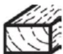
Blade for cutting wood.

This product is of protection class II. That means it is equipped with enhanced or double insulation.

Keep your hands away!

The product complies with the applicable European directives and an evaluation method of conformity for these directives was done.
WEEE symbol. Waste electrical products should not be disposed of with household waste. Please recycle where facilities exist. Check with your Local Authority or local store for recycling advice.
3. GENERAL DESCRIPTION
DESCRIPTION AND LOCATION OF MACHINE PARTS
- Operating handle
- Retractable blade guard release lever
- Upper fixed blade guard
- Spindle lock button
- Guard mounting plate
a. Bolt*
-
Lower retractable blade guard
-
Saw blade
a. Bolt*
b. Washer*
c. Locking flange*
d. Backing flange*
e. Spindle*
-
Fence
-
Bevel scale
a. Bevel scale pointer
-
Mounting hole
-
Mitre scale
a. Mitre scale pointer*
-
Table insert
-
Turntable
-
Base
-
Support assembly (left & right)
a. Fixing screw*
b. Support extension
c. Fixing knob
-
Screw clamp
a. Height adjustment knob*
b. Bracket*
c. Height adjustment pillar*
d. Locking knob* -
Air vents
-
Hex key (4 mm)
e. Plate*
f. Pillar locking knob
g. Pillar holder
- Fence extension
a. Fixing screw
-
Chip collection bag
-
On/off switch
-
Transport handle
a. Screw* (x 2)
-
Chip ejector opening
-
Power cord with plug
-
Bevel locking mechanism
-
Locking bolt
-
Turntable locking knob
-
Motor unit
-
Hex key (6 mm) with crosshead screwdriver

Note: Parts marked with * are not shown in this overview.
Please refer to the respective section in the instruction manual.
4. UNPACKING
- Unpack all parts and lay them on a flat, stable surface.
- Remove all packing materials and shipping devices, if applicable.
- Make sure the delivery contents are complete and free of any damage. If you find that parts are missing or show damage do not use the product but contact your dealer. Using an incomplete or damaged product represents a hazard to people and property.
- Ensure that you have all the accessories and tools needed for assembly and operation. This also includes suitable personal protective equipment.
⚠ WARNING! The product and the packaging are not children's toys! Children must not play with plastic bags, sheets and small parts! There is a danger of choking and suffocation!
You will need
| (items not supplied) (items supplied) | |
| Suitable personal protective equipment Support assembly (x 2) (15) | |
| Brush Hex key (4 mm) (28) | |
| Soft cloth Hex key (6 mm) with crosshead | |
| Light machine oil screwdriver (29) | |
| Coolant undiluted | |
| Mounting material (e. g. mounting set, working tools etc.) | undiluted |
5. ASSEMBLY
⚠ WARNING! The product must be fully assembled before operation! Do not use a product that is only partly assembled or assembled with damaged parts!
Follow the assembly instructions step-by-step and use the pictures provided as a visual guide to easily assemble the product!
Do not connect the product to power supply before it is completely assembled!

Note: Take care of small parts that are removed during assembly or when making adjustments. Keep them secure to avoid loss.
Operating position
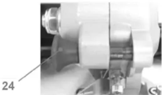
- Push the operating handle (1) downwards and disengage the locking bolt (24) from its locking position (Fig. 1).

Fig. 1
- Lift the operating handle (1) to its full height (Fig. 2).

natural_image
Mechanical robot with attached sensor and control panel, shown in two views (no text or symbols visible)Fig. 2
Support assembly

Note: Always use the support assembly during operation to ensure the stability of the workpiece.
- Slightly loosen the fixing screw (15a) with the hex key 4 mm (28) (Fig. 3, step 1). Do not remove it from the base.
- Slightly loosen the fixing knob (15c) on the support extension (15b).
- Insert the rod ends of the support assembly (15) through the holes on the support extension (15b) and then into the mounting holes on the base (14) (Fig. 3, step 2).
- Slide the support assembly inwards or outwards to the required position, if necessary.
- Tighten the fixing screw (15a) to secure it afterward (Fig. 3, step 3).
- Repeat the same application for the other support assembly.

Fig. 3
Screw clamp
The screw clamp (16) is pre-assembled. Refit it on either side of the base (14) if necessary.

Note: Attach the screw clamp (16) on the right side only if the bevel angle and the mitre angle is adjusted so that the motor housing does not interfere with the clamp.
- Slightly loosen the pillar locking knob (16f) on the pillar holder (16g).
- Insert the height adjustment pillar (16c) into the holder (16g).
- Tighten the knob (16f) to secure the pillar (16c) (Fig. 4).

Fig. 4
Transport handle
- Align the mounting holes and assemble the transport handle (20).
- Secure the transport handle (20) in position with the screws (20a) (Fig. 5).

Fig. 5
Chip collection bag
Attach the chip collection bag (18) onto the chip ejector opening (21) (Fig. 6). Ensure the opening clamp of the collection bag sits properly around the chip ejector opening.
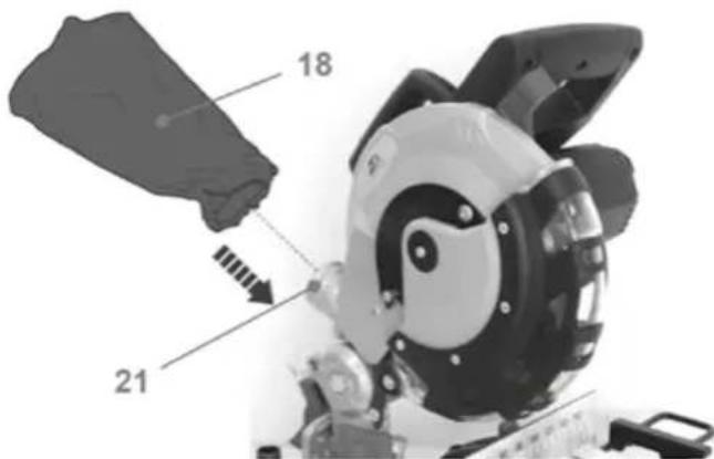
Fig. 6
⚠ WARNING! Make sure that the mounting surface is not warped as an uneven surface can cause binding and inaccurate sawing!
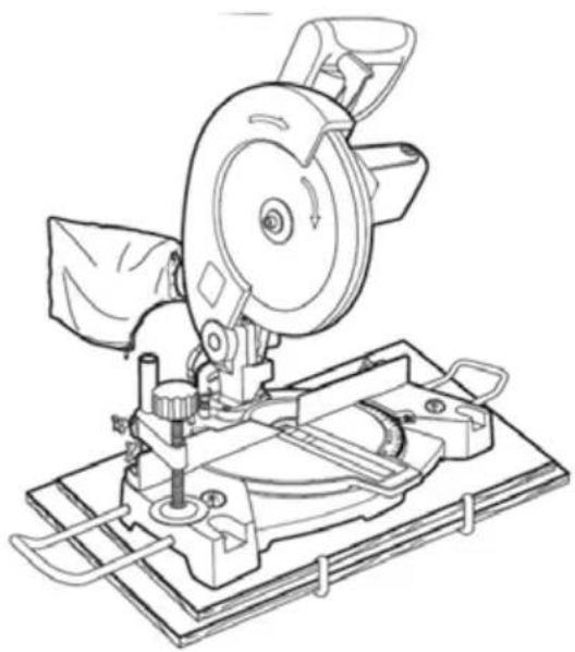
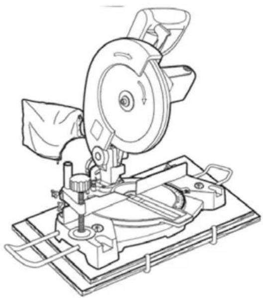
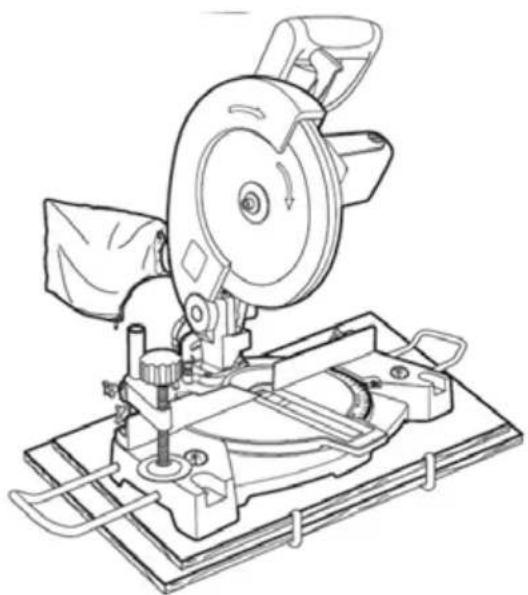
- There are 4 mounting holes (10) at each corner of the base (14) to facilitate bench mounting.
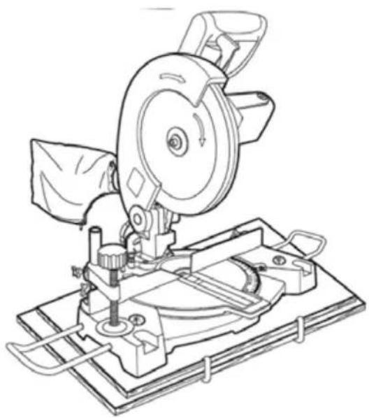
- Place the product on a level, horizontal bench or work table and fix the product on it with 4 mounting sets (not provided) (Fig. 7).
- If desired, mount the product to a piece of xx mm or thicker plywood which can then be clamped to your work support or moved to other job sites and re-clamped (Fig. 8).
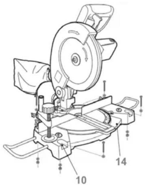
Fig. 7

natural_image
Technical line drawing of a cutting tool with a blade and base mount (no text or symbols)Fig. 8
Note: For reference only; will be replaced with actual product during PDF making.
6. INTENDED USE AND GENERAL OPERATION
Intended use
This sliding mitre saw MMIS210C is designated with a rated input of 1450 Watts.
This product is intended as a stationary machine for making straight lengthways and crossways cuts in wood and materials that are similar to wood (e.g. plywood, MDF and chipboard). Horizontal mitre angles of -45^ - +45^ as well as vertical bevel angles of 0^ - 45^ (L) are possible.
This product should not be used on other materials or those harmful to health. It is to be used for dry operation only without water or other cooling liquids.
For safety reasons it is essential to read the entire instruction manual before first operation and to observe all the instructions therein.
This product is intended for private domestic use only, not for any commercial trade use. It must not be used for any purposes other than those described.
Note: Regularly check for the correct blade angle as it may vary over time. Use proper measurement tool to ensure the saw blade is at a correct / suitable angle of the turntable as even a slight increment / decrement in the right angle can undermine the accuracy of your cuts.
Adjust the angle if necessary. It is recommended to assess the cutting accuracy of the saw blade on a scrap piece of workpiece before going forward with your cuts.
Mitre angle adjustment
- Loosen the turntable locking knob (25) (Fig. 9, step 1).
- Hold the operating handle (1) and rotate the turntable (13) until the pointer (11a) aligns with the desired angle on the mitre scale (11) (Fig. 9, step 2).
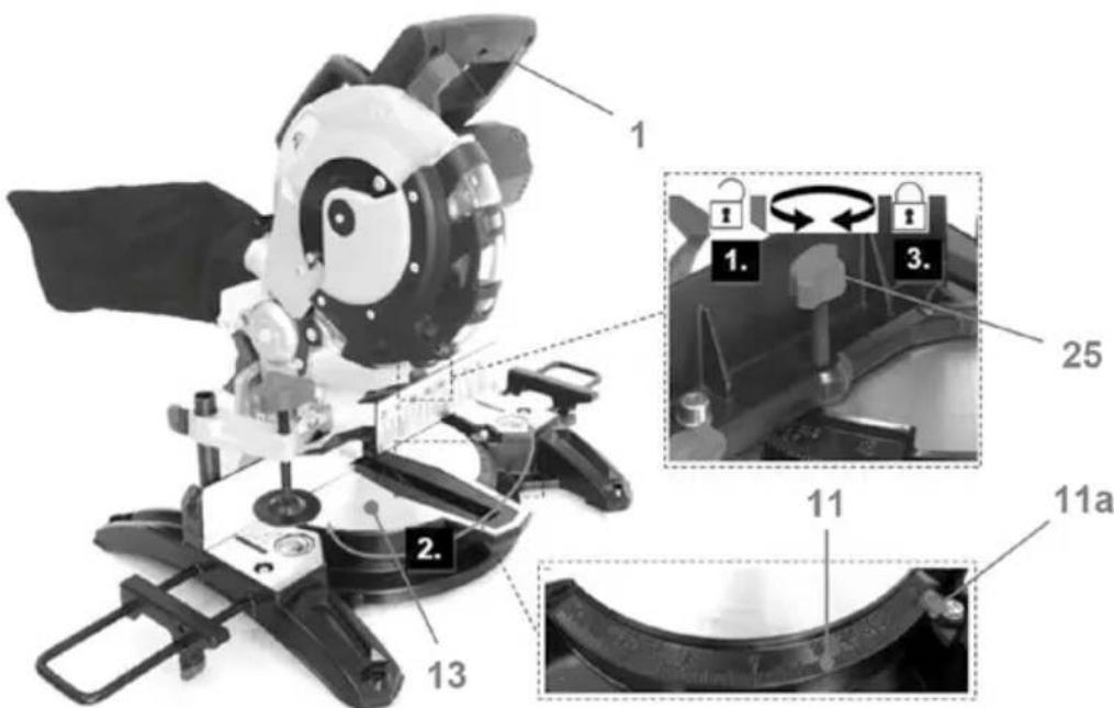
Fig. 9

Note: There are default adjustment positions for the mitre angle at 0^ , ±15^ , ±22.5^ , ±30^ , ±31.6^ and ±45^ .
- Tighten the turntable locking knob (25) afterward (Fig. 9, step 3).
Bevel angle adjustment
- Loosen the bevel locking mechanism (23).
- Move the operating handle (1) leftward until the pointer (9a) aligns with the desired angle on the bevel scale (9) (Fig. 10).
- Tighten the bevel locking mechanism (23).

Fig. 10
Support extension
Use the support assemblies (15) for supporting long workpieces. Use an additional support for extremely long workpiece if required.
- Slightly loosen the fixing screw (15a) with the hex key 4 mm (28) (Fig. 11, step 1). Do not remove it from the base (14).
- Slide the support assembly (15) inwards or outwards to the required position (Fig. 11, step 2).
- Tighten the fixing screw (15a) to secure it afterward (Fig. 11, step 3).
- Loosen the fixing knob (15c) (Fig. 11, step 4).
- Slide the support extension (15b) inwards or outwards to the required position (Fig. 11, step 5).
- Tighten the fixing knob (15c) to secure it afterward (Fig. 11, step 6).
- Ensure the saw blade does not interfere with the fence by conducting a "dry run" with the cutting head set to the required bevel and mitre angle.
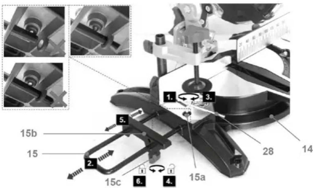
Fig. 11
Fence extension
Use the fence extension (17) for supporting long workpiece with sliding it along the fence (8) if necessary. This may be necessary to provide clearance for the blade when extreme mitre and bevel angles are selected.
- Loosen the pillar locking knob (16f) and remove the screw clamp (16).
- Loosen the fixing screw (17a) (Fig. 12, step 1).
- Adjust the fence extension (17) to the desired position (Fig. 12, step 2).
- Tighten the fixing screw (17a) afterward (Fig. 12, step 3).
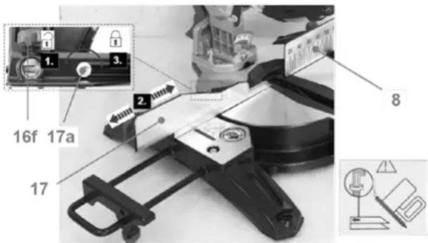
Fig. 12
- Ensure the blade does not interfere with the fence by conducting a 'dry run' with the cutting head set to the required bevel and mitre angle.
- Refit the screw clamp (16) and secure it with the pillar locking knob (16f).
Screw clamp
The screw clamp (16) can be assembled on either side of the base (14).

Note: Attach the screw clamp (16) on the right side only if the bevel angle and the mitre angle are adjusted so that the motor housing does not interfere with the clamp.
Use the screw clamp (16) to support the workpiece of different thickness by adjusting the height of the bracket (16b) and plate (16e).
- Loosen the knob (16d) on the height adjustment pillar (16c) and adjust the bracket (16b) to the desired height. Tighten the knob to secure the bracket.
- Adjust the height of the plate (16e) with screwing the height adjustment knob (16a) clockwise or anticlockwise (Fig. 13).

Fig. 13
- Screw the screw clamp (16) tightly to secure the workpiece before operating.

Note: Add a small scrap piece of thin plywood under the screw clamp to avoid marking the workpiece.
On/off switch
-
Squeeze the on/off switch (19) to switch the product on (Fig. 14).
-
Release the on/off switch (19) to switch the product off.

Fig. 14
General operation
- Check the product, its power cord and plug as well as accessories for damage before each use. Do not use the product if it is damaged or shows wear.
- Double check that the accessories and attachments are properly fixed.
- Always hold the product on its handle. Keep the handle dry to ensure safe support.
- Ensure that the air vents are always unobstructed and clear. Clean them if necessary with a soft brush. Blocked air vents may lead to overheating and damage the product.
- Switch the product off immediately if you are disturbed while working by other people entering the working area. Always let the product come to complete stop before moving away.
- Do not overwork yourself. Take regular breaks to ensure you can concentrate on the work and have full control over the product.
Mitre crosscut
A crosscut is made by cutting across the grain of the workpiece. A 90^ crosscut is made with the turntable set at 0^ . Mitre crosscuts are made with the turntable set at some angle other than 0^ .
- Push the operating handle (1) downwards and disengage the locking bolt (24) from its locking position (Fig. 15).
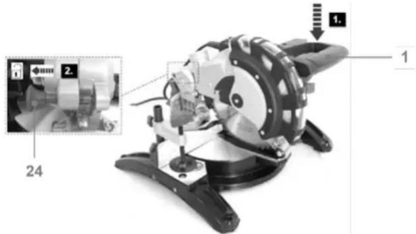
Fig. 15
- Lift the operating handle (1) to its full height (Fig. 16).

natural_image
Mechanical robot with attached sensor and control panel, shown in a technical view (no text or symbols visible)Fig. 16
- Loosen the turntable locking knob (25).
- Hold the operating handle (1) and rotate the turntable (13) until the pointer (11a) aligns with the desired angle on the mitre scale (11) (Fig. 17).

Note: There are default adjustment positions for the mitre angle at 0^ , ±15^ , ±22.5^ , ±30^ , ±31.6^ and ±45^ .
- Tighten the turntable locking knob (25) afterward.

Fig. 17
⚠ WARNING! Always tighten the turntable locking knob (25) before making a cut. Failure to do so could result in the turntable (13) moving during the cut and cause serious personal injury!

Note: Place the convex edge of the workpiece against the fence if it is warped. The workpiece could break and jam the saw blade if the concave edge is placed against the fence. Before switching on the product, perform a dry run of the cutting operation to check that there are no problems.

WARNING! Always make a test cut before cutting into the actual material!

WARNING! Press the blade guard release lever (2) and turn the lower retractable blade guard (6) by hand est if it is rotating smoothly. Always ensure the guard (6) should not flutter or be obstructed.
-
Place the workpiece flat on the turntable (13) with one edge against the fence (8) / fence extension (17).
-
Adjust the support extension (15b) and fence extension (17) if necessary.

Note: Always ensure the saw blade does not interfere with the fence or any other parts.
- Adjust the plate (16e) and the bracket (16b) to the desired height (Fig. 18) and then secure the workpiece with it.
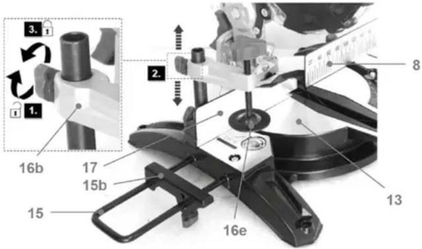
Fig. 18
-
Hold the operating handle (1) firmly and squeeze the on/off switch (19) (Fig. 19, Step 1). Allow the saw blade (7) to reach maximum speed.
-
Press the blade guard release lever (2) and slowly lower the blade to the workpiece (Fig. 19, step 2).
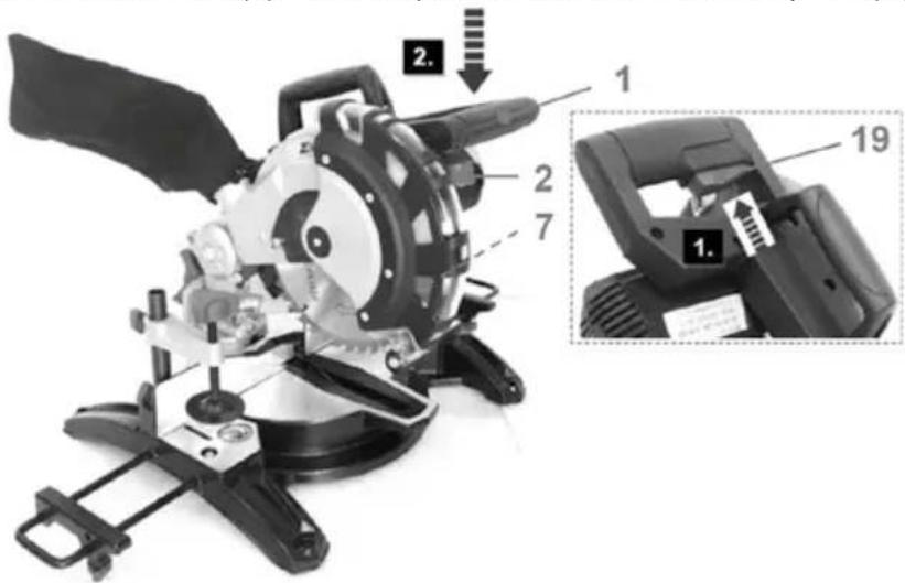
Fig. 19
- Release the on/off switch (19) and allow the saw blade to come to a complete stop before lifting it from the workpiece.
- Wait until the saw blade completely stops before removing the workpiece.
Bevel cut
A bevel cut is made by cutting across the grain of the workpiece with the saw blade angled to the fence and turntable. The turntable is set at the 0^ position and the blade set at an angle between 0^ and 45^ .
- Push the operating handle (1) downwards and disengage the locking bolt (24) from its locking position (Fig. 20).

Fig. 20
- Lift the operating handle (1) to its full height (Fig. 21).
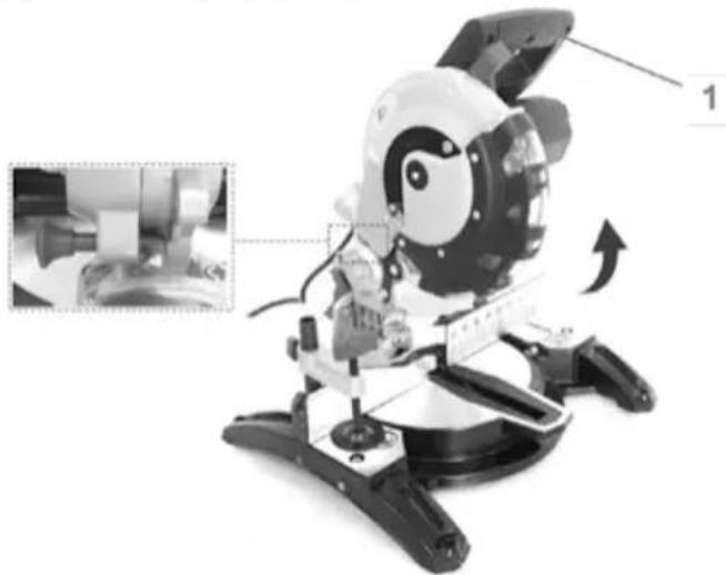
natural_image
Illustration of a small robot with a head-mounted sensor and control panel, showing mechanical components and a close-up inset (no text or symbols)Fig. 21
- Loosen the turntable locking knob (25) (Fig. 22, step 1).
- Hold the operating handle (1) and rotate the turntable (13) until the pointer (11a) aligns with 0° on the mitre scale (11) (Fig. 22, step 2).
- Tighten the turntable locking knob (25) afterward (Fig. 22, step 3).
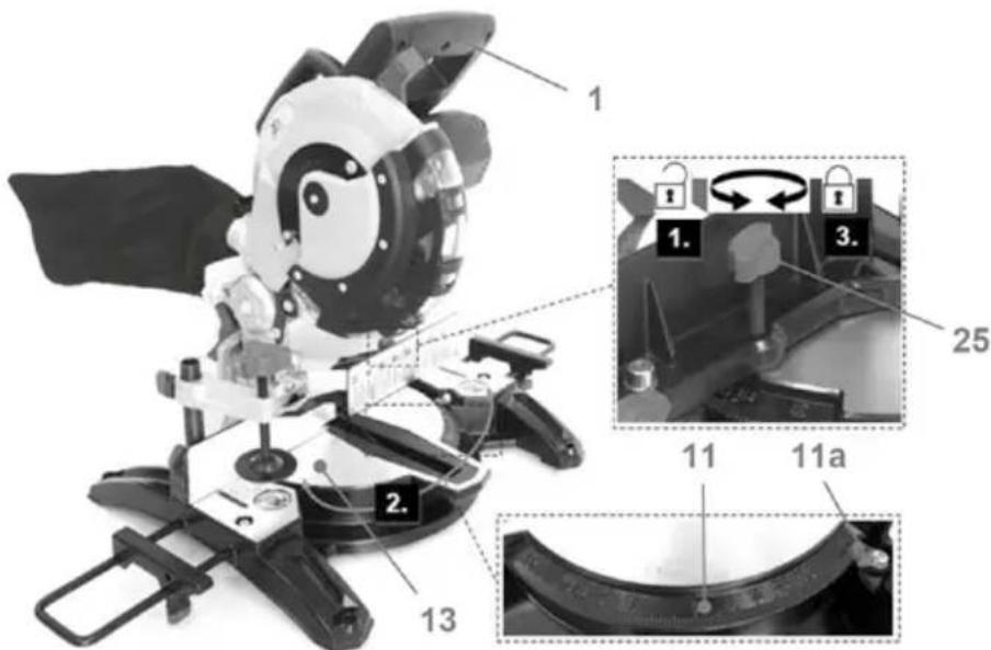
Fig. 22
⚠ WARNING! Always tighten the turntable locking knob (25) before making a cut. Failure to do so could result in the turntable (13) moving during the cut and cause serious personal injury!
- Loosen the bevel locking mechanism (23).
- Move the operating handle (1) leftward until the bevel pointer (9a) aligns with the desired angle on the bevel scale (9).
- Tighten the bevel locking mechanism (23) afterward (Fig. 23).

Fig. 23
Note: Place the convex edge of the workpiece against the fence if it is warped. The workpiece could break and jam the saw blade if the concave edge is placed against the fence.
Before switching on the product, perform a dry run of the cutting operation to check that there are no problems.
⚠ WARNING! Always make a test cut before cutting into the actual material!
⚠ WARNING! Press the blade guard release lever (2) and turn the lower retractable blade guard (6) by hand to test if it is rotating smoothly. Always ensure the guard (6) should not flutter or be obstructed.
-
Place the workpiece flat on the turntable (13) with one edge against the fence (8) / fence extension (17).
-
Adjust the support extension (15b) and fence extension (17) if necessary.

Note: Always ensure the saw blade does not interfere with the fence or any other parts.
- Adjust the plate (16e) and the bracket (16b) to the desired height (Fig. 24) and then secure the workpiece with it.
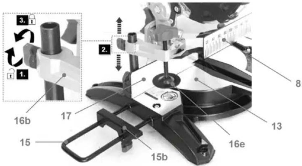
Fig. 24
-
Hold the operating handle (1) firmly and squeeze the on/off switch (19) (Fig. 25, step 1). Allow the saw blade (7) to reach maximum speed.
-
Press the blade guard release lever (2) and slowly lower the blade to the workpiece (Fig. 25, step 2).

Fig. 25
-
Release the on/off switch (19) and allow the saw blade to come to a complete stop before lifting it from the workpiece.
-
Wait until the saw blade completely stops before removing the workpiece.
Compound cuts
A compound mitre cut involves using a mitre angle and a bevel angle at the same time. It is used e.g. in making picture frames, cutting moldings, making boxes with sloping sides and for roof framing.
- Push the operating handle (1) downwards and disengage the locking bolt (24) from its locking position (Fig. 26).

Fig. 26
- Lift the operating handle (1) to its full height (Fig. 27).

natural_image
Black-and-white photo of a small robot with a head-mounted sensor, showing mechanical components and a close-up inset (no text or symbols visible)Fig. 27
- Loosen the turntable locking knob (25) (Fig. 28, step 1).
- Hold the operating handle (1) and rotate the turntable (13) until the pointer (11a) aligns with the desired angle on the mitre scale (11) (Fig. x, step 2).

Note: There are default adjustment positions for the mitre angle at 0^ , ±15^ , ±22.5^ , ±30^ , ±31.6^ and ±45^ .
- Tighten the turntable locking knob (25) afterward (Fig. x, step 3).

Fig. 28
⚠ WARNING! Always tighten the turntable locking knob (25) before making a cut. Failure to do so could result in the turntable (13) moving during the cut and cause serious personal injury!
-
Loosen the bevel locking mechanism (23).
-
Move the operating handle (1) leftward until the pointer (9a) aligns with the desired angle on the bevel scale (9).
-
Tighten the bevel locking mechanism (23) afterward (Fig. 29).

Fig. 29
Note: Place the convex edge of the workpiece against the fence if it is warped. The workpiece could break and jam the saw blade if the concave edge is placed against the fence.
Before switching on the product, perform a dry run of the cutting operation to check that there are no problems.
⚠ WARNING! Always make a test cut before cutting into the actual material!
⚠ WARNING! Press the blade guard release lever (2) and turn the lower retractable blade guard (6) by hand to test if it is rotating smoothly. Always ensure the guard (6) should not flutter or be obstructed.
-
Place the workpiece flat on the turntable (13) with one edge against the fence (8) / fence extension (17).
-
Adjust the support extension (15b) and fence extension (17) if necessary.

Note: Always ensure the saw blade does not interfere with the fence or any other parts.
- Adjust the plate (16e) and the bracket (16b) to the desired height (Fig. 30) and then secure the workpiece with it.

Fig. 30
- Hold the operating handle (1) firmly and squeeze the on/off switch (19) (Fig. 31, step 1). Allow the saw blade (7) to reach maximum speed.
- Press the blade guard release lever (2) and slowly lower the blade to the workpiece (Fig. 31, step 2).
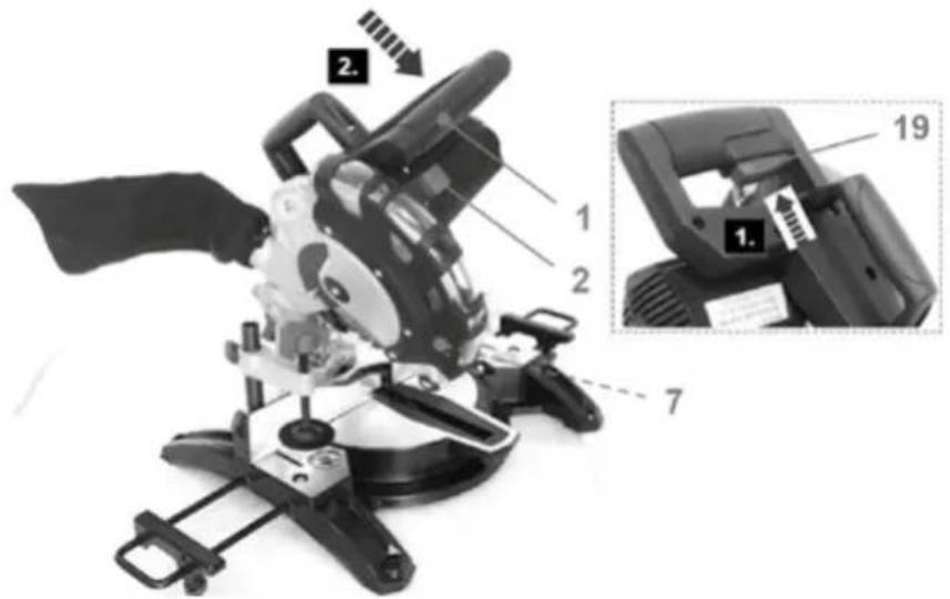
Fig. 31
- Release the on/off switch (19) and allow the saw blade to come to a complete stop before lifting it from the workpiece.
- Wait until the saw blade completely stops before removing the workpiece.
After use
- Switch the product off, disconnect it from the power supply and let it cool down.
- Check, clean and store the product as described below.
The golden rules for care
⚠ WARNING! Always switch the product off, disconnect it from the power supply and let the product cool down before performing inspection, maintenance and cleaning work!
- Keep the product clean. Remove debris from it after each use and before storage.
- Regular and proper cleaning will help ensure safe use and prolong the life of the product.
- Inspect the product before each use for worn and damaged parts. Do not operate it if you find broken and worn parts.
⚠ WARNING! Only perform repairs and maintenance work according to these instructions! All further works must be performed by a qualified specialist!
General cleaning
- Clean the product with a dry cloth. Use a brush for areas that are hard to reach.
- In particular clean the air vents (27) after every use with a cloth and brush.
- Remove stubborn dirt with high pressure air (max. 3 bar).

Note: Do not use chemical, alkaline, abrasive or other aggressive detergents or disinfectants to clean this product as they might be harmful to its surfaces.
- Check for worn or damaged parts. Replace worn parts as necessary or contact an authorised service centre for repair before using the product again.
7. MAINTENANCE
Before and after each use, check the product and accessories (or attachments) for wear and damage. If required, exchange them for new ones as described in this instruction manual. Observe the technical requirements.
Saw blade

Note:
-
Check the saw blade before every use for damage and wear. Replace it with a new one if required.
-
Only use a saw blade that is suitable for the intended application.
-
Do not use any abrasive wheels.
-
Only use a saw blade with diameter in accordance with the markings on the product.
-
Only use the saw blades which are marked with a rotation speed equal or higher than the speed marked on the product.
Replacing
⚠ WARNING! Always use the correct saw blade according to the intended use!
Observe the technical requirements of this product (see section Technical specifications) when purchasing and using saw blades!
Saw blades are very sharp and become hot during use! Handle them carefully! Wear safety gloves when handling saw blades in order to avoid injuries like burns and cuts!
⚠ WARNING! Never press the spindle lock button (4) whilst the spindle is rotating!
⚠ WARNING! Always allow the motor of the product to come to a complete stop before engaging the spindle lock! Always make sure that the spindle lock is disengaged before reconnecting the product to the power supply!
- Push the operating handle (1) downwards and disengage the locking bolt (24) from its locking position (Fig. 32).
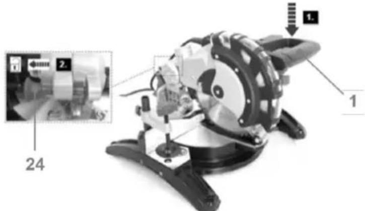
Fig. 32
- Lift the operating handle (1) to its full height (Fig. 33).
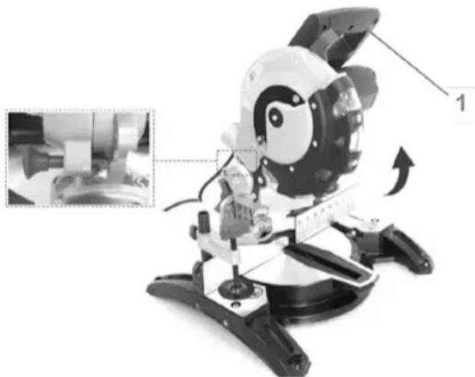
natural_image
Black-and-white photo of a child wearing a helmet and holding a device, with an inset close-up showing a small object (no visible text or symbols)Fig. 33
- Loosen the bolt (5a) on the guard mounting plate (5) with the hex key 4 ~mm (28) (Fig. 34).

Note: Do not use chemical, alkaline, abrasive or other aggressive detergents or disinfectants to clean this product as they might be harmful to its surfaces.

Fig. 34
- Press the blade guard release lever (2) and then rotate the guard mounting plate (5) and lower retractable blade guard (6) upwards (Fig. 35).

Note: pls. double check. According to our sample, the mounting plate (5) and blade guard (6) cannot be held in open position (as illustrated). Which means the user has to hold them with hand. Then the concerning is that the disassembly of saw blade actually requires both hands (keep spindle lock button pressed with one hand), loosen saw blade bolt with the other hand).

Fig. 35
- Press the spindle lock button (4) and rotate the saw blade (7) until the spindle (7e) locks.
- Keep the spindle lock button pressed and loosen the blade bolt (7a) with the hex key 6 mm (29).
- Remove the blade bolt (7a), washer (7b), locking flange (7c), saw blade (7) and backing flange (7d) (Fig. 36).

Fig. 36
- Clean the blade bolt (7a), washer (7b), locking flange (7c), saw blade (7), backing flange (7d), spindle (7e) and inside from dust.
- Wipe a drop of oil onto the washer (7b), flanges (7c, 7d) and the spindle (7e) if necessary.
- Replace the saw blade (7) with a new one of the same type. Always replace the saw blade immediately with a new one if it is cracked or damaged.

Note: Install the saw blade with the blade teeth and the arrow printed on the side of the blade pointing down at the front of the saw. The direction of the blade rotation is also stamped with an arrow on the lower retractable blade guard and the upper fixed blade guard.
- Lubricate the saw blade after each use to prolong the life of the blade and product. Apply light machine oil along the edge of the blade.
- Reassemble the backing flange (7d), saw blade (7), locking flange (7c), washer (7b) and blade bolt (7a) onto the spindle (7e), in reverse order as described above.
- Turn the saw blade by hand to test if it is rotating smoothly. The saw blade should not flutter.
- Fix the lower retractable blade guard (6) and mounting plate (5) in reverse order as described above.
- Switch the product on and let it run idle for about one minute, to confirm that the saw blade has been installed properly. If you find any abnormal vibration or excessive noise switch the product off and re-fit the saw blade according to the above instructions.
8. STORAGE
- Switch the product off and disconnect it from the power supply.
- Clean the product as described above.
- Loosen the turntable locking knob (25).
- Hold the operating handle (1) and rotate the turntable (13) until the mitre scale pointer (11a) aligns with 45^ .
- Retighten the turntable locking knob (25).
- Loosen the bevel locking mechanism (23). Move the operating handle (1) to the right until the bevel scale pointer (9a) aligns with 0°. Retighten the bevel locking mechanism (23).
- Press the blade guard release lever (2) and push the operating handle (1) fully downwards.
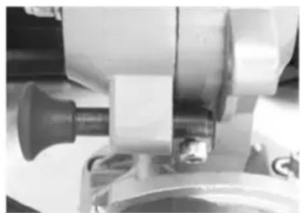
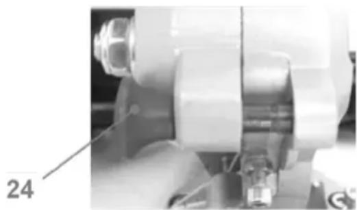
- Engage the locking bolt (24) to the locking position (Figs. 37, 38).
natural_image
Close-up of a mechanical assembly with a central component and flange (no visible text or symbols)Fig. 37
Operating position
natural_image
Close-up of a mechanical assembly with no visible text or symbolsFig. 38
Locking position
- Store the product and its accessories in a dark, dry, frost-free, well-ventilated place.
- Always store the product in a place that is inaccessible to children. The ideal storage temperature is between 10 C and 30 C.
- We recommend using the original package for storage or covering the product with a suitable cloth or enclosure to protect it against dust.
9. TROUBLESHOOTING
Suspected malfunctions are often due to causes that the users can fix themselves. Therefore check the product using this section. In most cases the problem can be solved quickly.
⚠ WARNING! Only perform the steps described within these instructions! All further inspection, maintenance and repair work must be performed by an authorised service centre or a similarly qualified specialist if you cannot solve the problem yourself!
| Problem Possible cause | Solution | |
| 1. Product does not start 1.1. | Not connected to power supply1.2. Defective power cord or plug1.3. Other electrical defect to the product | 1.1. Connect to power supply1.2. Check by a specialist electrician1.3. Check by a specialist electrician |
| 2. Product does not reach full power | 2.1. Extension cord not suitable for operation with this product2.2. Power source (e.g. generator) with too low voltage2.3. Blocked air vents | 2.1. Use a proper extension cord2.2. Connect to another power source2.3. Clean the air vents |
| 3. Product does not cut 3.1. | Not connected to power supply3.2. Saw blade is worn or damaged3.3. Bevel and mitre angle incorrectly adjusted | 3.1. Connect to power supply3.2. Replace with new one3.3. Check and adjust according to the instruction manual |
| 4. Unsatisfactory result 4.1. | Dull / damaged saw blade4.2. Cutting angle is incorrect4.3. Saw blade not suitable for work piece material4.4. Overheated saw blade4.5. Workpiece not clamped / placed properly | 4.1. Replace with new one4.2. Adjust the bevel and / or mitre cutting angle4.3. Use proper saw blade4.4. Let the work cool down before using again. Use coolant if needed4.5. Clamp / place the workpiece properly before cutting |
| 5. Excessive vibration / noise or exhaust | 5.1. Saw blade is dull / damaged5.2. Loose bolts / nuts | 5.1. Replace with a new one5.2. Tighten bolts / nuts |
10. DECLARATION OF CONFORMITY
FAST®
FAST ČR, a.s.
U Sanitasu 1621, 251 01 Ríčany, Czech Republic tel.: +420 323 204 111, fax: +420 323 204 110
EU DECLARATION OF CONFORMITY
Product/ brand: Mitre circular saw/ FIELDMANN
Type/ model: FDPP 201450-E as factory model M1YT-MQ-210HJ AC 230V; 50Hz; 1450W; L_PA = 96,86dB(A) , L_WA = 109,86dB(A)
Manufacturer: FAST ČR, a.s. U Sanitasu 1621, 251 01 Říčany, Czech Republic VAT no: CZ24777749
This declaration of conformity is issued under the sole responsibility of the manufacturer. Person in charge of completing the technical documentation: FAST ČR, a.s.
The object of the declaration described above is in conformity with the relevant Union harmonization legislation:
Directive MD 2006/42/EC Directive EMC 2014/30/EU Directive NEOE 2000/14/EC Directive RoHS 2011/65/EU+(EU)2015/863
The relevant harmonized standards and the other technical specifications:
EN IEC 6284-3-9:2020+A11 EN IEC 55014-1:2021 EN 62841-1:2015+A11 EN IEC 55014-2:2021 EN IEC 61000-3-2:2019+A1 EN 61000-3-3:2013+A1+A2

Place of issuance: Ríčany
Date of issuance: 10.11.2024
Name: Luboš Cinek Responsible Pe
Signature:
11. TECHNICAL SPECIFICATIONS
General
Rated voltage, frequency: 220 - 240 V\~, 50 Hz
Rated power input: 1450 W S1
Rated no load speed n0: 5000 min
Protection class: qqq
Weight: approx. 8.5 kg
Dimensions: approx. 460 x 360 x 355 mm
Cutting capacity
Dimensions (workpiece): min. xx x xx x xx mm
Mitre capacity: -45^-+45^
Bevel capacity: 0° - 45° (L)
Mitre / Bevel 0° / 0°: 120 x 60 mm
Mitre / Bevel 0° / 45°: 120 x 34 mm
Mitre / Bevel 45° / 0°: 85 x 60 mm
Mitre / Bevel 45° / 45°: 85 x 34 mm
Saw blade
Outer diameter: ∅ 210 mm
Bore diameter: ∅ 30 mm
Thickness: 2.8 mm
Teeth number: 40 T
Max. speed nmax: 7000 min ^-1
Cutting material: wood
Noise and vibration level
Sound power level LWA (dB(A))
LWA=109.86dB(A),
KWA=3.0dB(A)
Sound pressure level LpA (dB(A))
LpA=96.86dB(A),
KpA=3dB(A)
The sound values have been determined according to noise test code given in EN 62841-1 and EN 62841-3-9, using the basic standards EN ISO 11201 and EN ISO 3744.
The sound intensity level for the operator may exceed 80 dB(A) and ear protection measures are necessary.
The declared vibration value has been measured in accordance with a standard test method (according to EN 62841-1 and EN 62841-3-9) and may be used for comparing one product with another. The declared vibration value may also be used in a preliminary assessment of exposure.
12. DISPOSAL
INSTRUCTIONS AND INFORMATION ON DISPOSAL OF USED PACKAGING
Put any used package material to the place determined by the municipality for waste disposal.

DISPOSAL OF USED ELECTRIC AND ELECTRONIC EQUIPMEN
This symbol on products or accompanying documents means that used electric or electronic products must not be put to ordinary municipal waste. Hand over such products to determined collection points for proper disposal, restoration and recycling. Alternatively, in some countries of the European Union or other European countries you can return your products to your local dealer when you buy an equivalent new product. By dutiful disposal of this product you can preserve precious natural resources and you help prevent any potential adverse effects on the environment and human health which could be the results of wrong waste disposal. Ask your local authority or the nearest collection point for additional details.
In case of improper disposal of this waste kind penalties can be imposed in accordance with national regulations.
FOR COMPANIES IN THE EUROPEAN UNION COUNTRIES
Should you want to dispose of electric and electronic devices, ask your dealer or vendor for necessary information.
DISPOSAL IN OTHER COUNTRIES OUTSIDE THE EUROPEAN UNION
Should you want to dispose of this product, ask your local authorities or your dealer for necessary information about disposal method

This product fulfils all basic requirements of the EU directives that apply to it.
Text, design and technical specifications can change without prior notice and we reserve the right for their change.
User manual in the original language.
natural_image
Mechanical robot with attached sensor and control panel, shown in a black-and-white photo with an inset close-up of the device (no visible text or symbols)Obr. 2
Sestava podpěry

Obr. 7
natural_image
Technical line drawing of a mechanical cutting tool with no visible text or symbolsObr. 8
natural_image
Close-up of a black handheld device with a label pointing to the number 19 (no visible text or symbols on the device itself)Obr. 14
Základní ovládání
natural_image
Mechanical robot with attached sensor and control panel, shown with a close-up inset of mechanical components (no text or symbols visible)Obr. 16
Obr. 19
Obr. 20
natural_image
Mechanical robot with a close-up inset showing a close-up of its mechanical components (no visible text or symbols)Obr. 21
Obr. 25
Obr. 26
natural_image
Black-and-white photo of a small robotic device with a close-up inset showing a close-up of its mechanical components (no visible text or symbols)Obr. 27
Obr. 31
Obr. 32
natural_image
Black-and-white photo of a child wearing a helmet and holding a device, with an inset close-up showing a small object (no visible text or symbols)Obr. 33
Obr. 36
natural_image
Close-up of a mechanical component with a cylindrical shaft and flange (no visible text or symbols)natural_image
Close-up of a mechanical assembly with no visible text or symbolsU Sanitasu 1621, 251 01 Říčany, Czech Republic
tel.: +420 323 204 111, fax: +420 323 204 110
EU PROHLÁŠENÍ O SHODĚ
U Sanitasu 1621, 251 01 Říčany, Czech Republic
DIČ: CZ24777749
Obr. 1
natural_image
Robot-like robot with mechanical components and a close-up inset showing a close-up of its motion (no visible text or symbols)Obr. 2
Zostava podpery

Obr. 7
natural_image
Technical line drawing of a mechanical cutting tool with no visible text or symbolsObr. 8
natural_image
Mechanical robot with mechanical components and a close-up inset showing a close-up of a device (no visible text or symbols)Obr. 16
Obr. 20
natural_image
Mechanical robot with attached sensor and control panel, shown in a technical view (no text or symbols visible)Obr. 21
Obr. 25
Obr. 26
natural_image
Black-and-white photo of a robotic robot with mechanical components, shown with an inset close-up of its motion (no text or symbols visible)Obr. 27
Obr. 31
Obr. 32
natural_image
Black-and-white photo of a child wearing a helmet and holding a device, with an inset close-up showing a small object (no visible text or symbols)Obr. 33
Obr. 35
natural_image
Close-up of mechanical components with no visible text or symbolsObr. 37
Pracovná poloha
natural_image
Close-up of a mechanical assembly with cylindrical components and a labeled part '24' (no readable text or symbols beyond label)Obr. 38
Zaisfovacia poloha
U Sanitasu 1621, 251 01 Říčany, Czech Republic
VAT no: CZ24777749
natural_image
Mechanical robot with attached sensor and control panel, shown in a technical view (no text or symbols visible)- ábra
- ábra
natural_image
Technical line drawing of a mechanical cutting tool with no visible text or symbols- ábra
natural_image
Mechanical robot with mechanical components and a close-up inset showing a close-up of a device (no visible text or symbols)natural_image
Illustration of a robotic device with a close-up inset showing mechanical components (no text or symbols)natural_image
Black-and-white photo of a small robot-like device with a head-mounted sensor, shown with an inset close-up of its body (no visible text or symbols)natural_image
Robot toy with mechanical components and a close-up inset showing a mechanical assembly (no visible text or symbols)natural_image
Close-up of mechanical components with no visible text or symbols- ábra
Munkahelyzet

natural_image
Close-up of a mechanical assembly with no visible text or symbolsEU DECLARATION OF CONFORMITY
Product/ brand: Mitre circular saw/ FIELDMANN
Type/ model: FDPP 201450-E as factory model M1YT-MQ-210HJ AC 230V; 50Hz; 1450W; L_PA = 96,86dB(A) , L_WA = 109,86dB(A)
Manufacturer: FAST ČR, a.s. U Sanitasu 1621, 251 01 Říčany, Czech Republic VAT no: CZ24777749
This declaration of conformity is issued under the sole responsibility of the manufacturer. Person in charge of completing the technical documentation: FAST ČR, a.s.
The object of the declaration described above is in conformity with the relevant Union harmonization legislation:
Directive MD 2006/42/EC Directive EMC 2014/30/EU Directive NEOE 2000/14/EC Directive RoHS 2011/65/EU+(EU)2015/863
The relevant harmonized standards and the other technical specifications:
EN IEC 6284-3-9:2020+A11 EN IEC 55014-1:2021 EN 62841-1:2015+A11 EN IEC 55014-2:2021 EN IEC 61000-3-2:2019+A1 EN 61000-3-3:2013+A1+A2

Place of issuance: Ríčany
Date of issuance: 10.11.2024
Name: Luboš Cinek Responsible Pe
Signature:

11. MÜSZAKI ADATOK
Általános
Rys. 1
natural_image
Mechanical robot with mechanical components and a close-up inset showing a close-up of a mechanical assembly (no visible text or symbols)Rys. 2
Zestaw wspornika

Rys. 7
natural_image
Technical line drawing of a mechanical cutting tool with no visible text or symbolsRys. 8
natural_image
Mechanical robot with mechanical components and a close-up inset showing a close-up of a device (no visible text or symbols)Rys. 16
Rys. 19
natural_image
Mechanical robot with attached sensor and mechanical components, shown in a technical view (no text or symbols visible)Rys. 21
natural_image
Black-and-white photo of a small robot with a head-mounted sensor and control panel, showing mechanical components and a close-up inset (no text or symbols visible)Rys. 27
Rys. 31
Rys. 32
natural_image
Black-and-white photo of a robotic device with a close-up inset showing a mechanical component (no visible text or symbols)Rys. 33
natural_image
Close-up of mechanical components with no visible text or symbolsnatural_image
Close-up of a mechanical assembly with no visible text or symbolsEU DECLARATION OF CONFORMITY
Product/ brand: Mitre circular saw/ FIELDMANN
Type/ model: FDPP 201450-E as factory model M1YT-MQ-210HJ AC 230V; 50Hz; 1450W; L_PA = 96,86dB(A) , L_WA = 109,86dB(A)
Manufacturer: FAST ČR, a.s. U Sanitasu 1621, 251 01 Říčany, Czech Republic VAT no: CZ24777749
This declaration of conformity is issued under the sole responsibility of the manufacturer. Person in charge of completing the technical documentation: FAST ČR, a.s.
The object of the declaration described above is in conformity with the relevant Union harmonization legislation:
Directive MD 2006/42/EC Directive EMC 2014/30/EU Directive NEOE 2000/14/EC Directive RoHS 2011/65/EU+(EU)2015/863
The relevant harmonized standards and the other technical specifications:
EN IEC 6284-3-9:2020+A11 EN IEC 55014-1:2021 EN 62841-1:2015+A11 EN IEC 55014-2:2021 EN IEC 61000-3-2:2019+A1 EN 61000-3-3:2013+A1+A2

Place of issuance: Ríčany
Date of issuance: 10.11.2024
Name: Luboš Cinek Responsible Person
Signature:

11. DANE TECHNICZNE
Ogólne
natural_image
Green and black toy cutlery with a ruler for scale (no text or symbols visible)
FIELDMANN®
Home & Garden Performance


- FIELDMANN®
- Compound Mitre Saw
- USER'S MANUAL
- TABLE OF CONTENTS
- GENERAL SAFETY INSTRUCTIONS
- Important safety warnings
- Packaging
- Instructions for use
- Carefully read, remember and keep these safety instructions
- Workplace
- Electrical Safety
- Personal Safety
- Power Tool Use and Maintenance
- Use of Cordless Power Tools
- Service
- SYMBOLS
- yyWxx
- GENERAL DESCRIPTION
- DESCRIPTION AND LOCATION OF MACHINE PARTS
- UNPACKING
- ASSEMBLY
- Operating position
- Support assembly
- Screw clamp
- Transport handle
- Chip collection bag
- INTENDED USE AND GENERAL OPERATION
- Intended use
- Mitre angle adjustment
- Bevel angle adjustment
- Support extension
- Fence extension
- On/off switch
- General operation
- Mitre crosscut
- Bevel cut
- Compound cuts
- After use
- The golden rules for care
- General cleaning
- MAINTENANCE
- Saw blade
- Note:
- Replacing
- STORAGE
- TROUBLESHOOTING
- DECLARATION OF CONFORMITY
- FAST®
- EU DECLARATION OF CONFORMITY
- TECHNICAL SPECIFICATIONS
- General
- Cutting capacity
- Noise and vibration level
- DISPOSAL
- INSTRUCTIONS AND INFORMATION ON DISPOSAL OF USED PACKAGING
- DISPOSAL OF USED ELECTRIC AND ELECTRONIC EQUIPMEN
- FOR COMPANIES IN THE EUROPEAN UNION COUNTRIES
- DISPOSAL IN OTHER COUNTRIES OUTSIDE THE EUROPEAN UNION
- Sestava podpěry
- Základní ovládání
- EU PROHLÁŠENÍ O SHODĚ
- Zostava podpery
- MÜSZAKI ADATOK
- Általános
- Zestaw wspornika
- DANE TECHNICZNE
- Ogólne
Brand : Fieldmann
Model : FDPP 201450-E
Category : Saw