
MAJESTY 400 - Scooter YAMAHA - Free user manual and instructions
Find the device manual for free MAJESTY 400 YAMAHA in PDF.
| Product type | Scooter |
| Brand | YAMAHA |
| Model | MAJESTY 400 (YP400A) |
| Dimensions (L \u00d7 W \u00d7 H) | 2230 \u00d7 780 \u00d7 1380 mm |
| Seat height | 760 mm |
| Wheelbase | 1565 mm |
| Curb weight | 223 kg |
| Engine | 4-stroke, single cylinder, liquid-cooled, DOHC, 395 cm\u00b3 |
| Bore \u00d7 stroke | 83.0 \u00d7 73.0 mm |
| Compression ratio | 10.6:1 |
| Ignition | TCI (digital) |
| Starting | Electric |
| Fuel tank capacity | 14 L (unleaded 91 RON) |
| Transmission | Automatic belt drive |
| Front brakes | Dual disc (ABS) |
| Rear brake | Single disc (ABS) |
| Front tires | 120/80-14M/C 58S (tubeless) |
| Rear tires | 150/70-13M/C 64S (tubeless) |
| Maximum load | 185 kg (rider + passenger + luggage) |
| Battery | 12 V, 8.0 Ah (GT9B-4) |
| Front lighting | Halogen 12V 60/55W \u00d71 + 12V 55W \u00d71 |
| Anti-theft | Immobilizer system with coding key (red) |
| Engine oil maintenance | Change every 5000 km, 1.5 L (without filter), 1.7 L (with filter) |
Frequently Asked Questions - MAJESTY 400 YAMAHA
User questions about MAJESTY 400 YAMAHA
0 question about this device. Answer the ones you know or ask your own.
Ask a new question about this device
Download the instructions for your Scooter in PDF format for free! Find your manual MAJESTY 400 - YAMAHA and take your electronic device back in hand. On this page are published all the documents necessary for the use of your device. MAJESTY 400 by YAMAHA.
USER MANUAL MAJESTY 400 YAMAHA
Read this manual carefully before operating this vehicle. This manual should stay with this vehicle if it is sold.

YAMAHA
YAMAHA MOTOR ELECTRONICS CO., LTD.
1450-6, Mori, Mori-machi, Shuchi-gun, Shizuoka-ken, 437-0292 Japan
DECLARATION of CONFORMITY
We
Company:YAMAHA MOTOR ELECTRONICS CO.,LTD.
Address: 1450-6, Mori, Mori-Machi, Shuchi-gun, Shizuoka-Ken, 437-0292 Japan
Hereby declare that the product:
Kind of equipment: IMMOBILIZER
Type-designation: 5SL-00
is in compliance with following norm(s) or documents:
R&TTE Directive(1999/5/EC)
EN300 330-2 v1.1.1(2001-6), EN60950-1(2001)
Two or Three-Wheel Motor Vehicles Directive(97/24/EC: Chapter 8, EMC)
Place of issue: Shizuoka, Japan
General manager of quality assurance div.
Welcome to the Yamaha world of motorcycling!
As the owner of the YP400A, you are benefiting from Yamaha's vast experience and newest technology regarding the design and manufacture of high-quality products, which have earned Yamaha a reputation for dependability.
Please take the time to read this manual thoroughly, so as to enjoy all advantages of your YP400A. The Owner's Manual does not only instruct you in how to operate, inspect and maintain your scooter, but also in how to safeguard yourself and others from trouble and injury.
In addition, the many tips given in this manual will help keep your scooter in the best possible condition. If you have any further questions, do not hesitate to contact your Yamaha dealer.
The Yamaha team wishes you many safe and pleasant rides. So, remember to put safety first!
Yamaha continually seeks advancements in product design and quality. Therefore, while this manual contains the most current product information available at the time of printing, there may be minor discrepancies between your scooter and this manual. If there is any question concerning this manual, please consult a Yamaha dealer.

EWA12411
Please read this manual carefully and completely before operating this scooter.
Particularly important information is distinguished in this manual by the following notations:
| This is the safety alert symbol. It is used to alert you to potential personal injury hazards. Obey all safety messages that follow this symbol to avoid possible injury or death. | |
| WARNING | A WARNING indicates a hazardous situation which, if not avoided, could result in death or serious injury. |
| NOTICE | A NOTICE indicates special precautions that must be taken to avoid damage to the vehicle or other property. |
| TIP | A TIP provides key information to make procedures easier or clearer. |
EAU10200
YP400A
OWNER'S MANUAL
©2009 by Yamaha Motor Co., Ltd.
1st edition, February 2009
All rights reserved.
Any reprinting or unauthorized use
without the written permission of
Yamaha Motor Co., Ltd.
is expressly prohibited.
Printed in Japan.
SAFETY INFORMATION 1-1
Further safe-riding points 1-5
DESCRIPTION 2-1
Left view 2-1
Right view 2-2
Controls and instruments. 2-3
INSTRUMENT AND CONTROL
FUNCTIONS 3-1
Immobilizer system 3-1
Main switch/steering lock 3-2
Indicator and warning lights 3-3
Speedometer 3-5
Tachometer 3-5
Multi-function display 3-5
Anti-theft alarm (optional) 3-9
Handlebar switches 3-10
Front brake lever 3-11
Rear brake lever 3-12
Rear brake lock lever 3-12
ABS 3-13
Fuel tank cap 3-14
Fuel 3-15
Catalytic converters 3-16
Seats 3-17
Adjusting the rider seat 3-18
Storage compartments 3-19
Adjusting the shock absorber assemblies 3-21
Sidestand 3-21
Ignition circuit cut-off system 3-22
FOR YOUR SAFETY -
Starting the engine 5-1
Starting off 5-2
Acceleration and deceleration 5-2
Braking 5-3
Tips for reducing fuel consumption 5-3
Engine break-in 5-4
Parking 5-4
PERIODIC MAINTENANCE AND
ADJUSTMENT 6-1
Owner's tool kit 6-1
Periodic maintenance chart for the emission control system 6-3
General maintenance and lubrication chart 6-4
Removing and installing cowlings and panels 6-7
Checking the spark plug 6-10
Engine oil and oil filter element 6-12
Final transmission oil 6-15
Coolant 6-16
Air filter elements and check hoses and V-belt case air filter element 6-18
Checking the throttle cable free play 6-20
Valve clearance 6-21
Tires 6-21
Cast wheels 6-23
Front and rear brake lever free play 6-23
Adjusting the rear brake lock lever cable 6-24
Checking the front and rear brake pads 6-25
Checking the brake fluid level .... 6-25
Changing the brake fluid 6-26
Checking and lubricating the cables 6-27
Checking and lubricating the throttle grip and cable 6-27
Lubricating the front and rear brake levers 6-27
Checking and lubricating the centerstand and sidestand 6-28
Checking the front fork 6-29
Checking the steering 6-29
Checking the wheel bearings 6-30
Battery 6-30
Replacing the fuses 6-31
Replacing a headlight bulb 6-33
Tail/brake light 6-33
Front turn signal light 6-33
Replacing a rear turn signal light bulb 6-34
Replacing the license plate light bulb 6-34
Auxiliary light bulb 6-35
Troubleshooting 6-35
Troubleshooting charts 6-37
SCOOTER CARE AND
STORAGE 7-1
Matte color caution 7-1
Care 7-1
Storage 7-3
SPECIFICATIONS 8-1
CONSUMER INFORMATION 9-1
Identification numbers 9-1
EAU10263
Be a Responsible Owner
As the vehicle's owner, you are responsible for the safe and proper operation of your scooter.
Scooters are single-track vehicles.
Their safe use and operation are dependent upon the use of proper riding techniques as well as the expertise of the operator. Every operator should know the following requirements before riding this scooter.
He or she should:
- Obtain thorough instructions from a competent source on all aspects of scooter operation.
- Observe the warnings and maintenance requirements in this Owner's Manual.
- Obtain qualified training in safe and proper riding techniques.
- Obtain professional technical service as indicated in this Owner's Manual and/or when made necessary by mechanical conditions.
Safe Riding
Perform the pre-operation checks each time you use the vehicle to make sure it is in safe operating condition. Failure to inspect or maintain the vehicle properly increases the possibility of an accident or equipment damage. See page 4-1 for a list of pre-operation checks.
- This scooter is designed to carry the operator and a passenger.
- The failure of motorists to detect and recognize scooters in traffic is the predominating cause of automobile/scooter accidents. Many accidents have been caused by an automobile driver who did not see the scooter. Making yourself conspicuous appears to be very effective in reducing the chance of this type of accident.
Therefore:
- Wear a brightly colored jacket.
-
Use extra caution when you are approaching and passing through intersections, since intersections are the most likely places for scooter accidents to occur.
-
Ride where other motorists can see you. Avoid riding in another motorist's blind spot.
-
Many accidents involve inexperienced operators. In fact, many operators who have been involved in accidents do not even have a current driver's license.
-
Make sure that you are qualified and that you only lend your scooter to other qualified operators.
- Know your skills and limits. Staying within your limits may help you to avoid an accident.
We recommend that you practice riding your scooter where there is no traffic until you have become thoroughly familiar with the scooter and all of its controls. - Many accidents have been caused by error of the scooter operator. A typical error made by the operator is veering wide on a turn due to excessive speed or undercornering (insufficient lean angle for the speed).
Always obey the speed limit and never travel faster than warranted by road and traffic conditions.
Always signal before turning or changing lanes. Make sure that other motorists can see you.
-
The posture of the operator and passenger is important for proper control.
-
The operator should keep both hands on the handlebar and both feet on the operator footrests during operation to maintain control of the scooter.
-
The passenger should always hold onto the operator, the seat strap or grab bar, if equipped, with both hands and keep both feet on the passenger footrests. Never carry a passenger unless he or she can firmly place both feet on the passenger footrests.
-
Never ride under the influence of alcohol or other drugs.
- This scooter is designed for on-road use only. It is not suitable for off-road use.
Protective apparel
The majority of fatalities from scooter accidents are the result of head injuries. The use of a safety helmet is the single most critical factor in the prevention or reduction of head injuries.
Always wear an approved helmet.
- Wear a face shield or goggles. Wind in your unprotected eyes could contribute to an impairment of vision that could delay seeing a hazard.
- The use of a jacket, substantial shoes, trousers, gloves, etc., is effective in preventing or reducing abrasions or lacerations.
- Never wear loose-fitting clothes, otherwise they could catch on the control levers or wheels and cause injury or an accident.
Always wear protective clothing that covers your legs, ankles, and feet. The engine or exhaust system become very hot during or after operation and can cause burns. - A passenger should also observe the above precautions.
Avoid Carbon Monoxide Poisoning
All engine exhaust contains carbon monoxide, a deadly gas. Breathing carbon monoxide can cause headaches, dizziness, drowsiness, nausea, confusion, and eventually death.
Carbon Monoxide is a colorless, odorless, tasteless gas which may be present even if you do not see or smell any engine exhaust. Deadly levels of carbon monoxide can collect rapidly and you can quickly be overcome and unable to save yourself. Also, deadly levels of carbon monoxide can linger for hours or days in enclosed or poorly ventilated areas. If you experience any symptoms of carbon monoxide poisoning, leave the area immediately, get fresh air, and SEEK MEDICAL TREATMENT.
- Do not run engine indoors. Even if you try to ventilate engine exhaust with fans or open windows and doors, carbon monoxide can rapidly reach dangerous levels.
- Do not run engine in poorly ventilated or partially enclosed areas such as barns, garages, or car
ports.
- Do not run engine outdoors where engine exhaust can be drawn into a building through openings such as windows and doors.
Loading
Adding accessories or cargo to your scooter can adversely affect stability and handling if the weight distribution of the scooter is changed. To avoid the possibility of an accident, use extreme caution when adding cargo or accessories to your scooter. Use extra care when riding a scooter that has added cargo or accessories. Here, along with the information about accessories below, are some general guidelines to follow if loading cargo to your scooter: The total weight of the operator, passenger, accessories and cargo must not exceed the maximum load limit. Operation of an overloaded vehicle could cause an accident.
Maximum load:
185 kg (408 lb)
When loading within this weight limit,
keep the following in mind:
-
Cargo and accessory weight should be kept as low and close to the scooter as possible. Securely pack your heaviest items as close to the center of the vehicle as possible and make sure to distribute the weight as evenly as possible on both sides of the scooter to minimize imbalance or instability.
-
Shifting weights can create a sudden imbalance. Make sure that accessories and cargo are securely attached to the scooter before riding. Check accessory mounts and cargo restraints frequently.
-
Properly adjust the suspension for your load (suspension-adjustable models only), and check the condition and pressure of your tires.
-
Never attach any large or heavy items to the handlebar, front fork, or front fender. Such items can create unstable handling or a slow steering response.
-
This vehicle is not designed to pull a trailer or to be attached to a sidecar.
Genuine Yamaha Accessories
Choosing accessories for your vehicle is an important decision. Genuine Yamaha accessories, which are available only from a Yamaha dealer, have been designed, tested, and approved by Yamaha for use on your vehicle.
Many companies with no connection to Yamaha manufacture parts and accessories or offer other modifications for Yamaha vehicles. Yamaha is not in a position to test the products that these aftermarket companies produce. Therefore, Yamaha can neither endorse nor recommend the use of accessories not sold by Yamaha or modifications not specifically recommended by Yamaha, even if sold and installed by a Yamaha dealer.
Aftermarket Parts, Accessories, and Modifications
While you may find aftermarket products similar in design and quality to genuine Yamaha accessories, recognize that some aftermarket accessories or modifications are not suitable because of potential safety hazards to you or others. Installing aftermarket prod
ucts or having other modifications performed to your vehicle that change any of the vehicle's design or operation characteristics can put you and others at greater risk of serious injury or death. You are responsible for injuries related to changes in the vehicle.
Keep the following guidelines in mind, as well as those provided under "Loading" when mounting accessories.
- Never install accessories or carry cargo that would impair the performance of your scooter. Carefully inspect the accessory before using it to make sure that it does not in any way reduce ground clearance or cornering clearance, limit suspension travel, steering travel or control operation, or obscure lights or reflectors.
- Accessories fitted to the handlebar or the front fork area can create instability due to improper weight distribution or aerodynamic changes. If accessories are added to the handlebar or front fork area, they must be as lightweight as possible and
should be kept to a minimum.
- Bulky or large accessories may seriously affect the stability of the scooter due to aerodynamic effects. Wind may attempt to lift the scooter, or the scooter may become unstable in cross winds. These accessories may also cause instability when passing or being passed by large vehicles.
- Certain accessories can displace the operator from his or her normal riding position. This improper position limits the freedom of movement of the operator and may limit control ability, therefore, such accessories are not recommended.
- Use caution when adding electrical accessories. If electrical accessories exceed the capacity of the scooter's electrical system, an electric failure could result, which could cause a dangerous loss of lights or engine power.
Aftermarket Tires and Rims
The tires and rims that came with your scooter were designed to match the performance capabilities and to provide the best combination of handling, braking, and comfort. Other tires, rims, sizes, and combinations may not be appropriate. Refer to page 6-21 for tire specifications and more information on replacing your tires.
EAU10372
Further safe-riding points
- Be sure to signal clearly when making turns.
- Braking can be extremely difficult on a wet road. Avoid hard braking, because the scooter could slide. Apply the brakes slowly when stopping on a wet surface.
- Slow down as you approach a corner or turn. Once you have completed a turn, accelerate slowly.
- Be careful when passing parked cars. A driver might not see you and open a door in your path.
- Railroad crossings, streetcar rails, iron plates on road construction sites, and manhole covers become extremely slippery when wet. Slow down and cross them with caution. Keep the scooter upright, otherwise it could slide out from under you.
- The brake pads could get wet when you wash the scooter. After washing the scooter, check the brakes before riding.
Always wear a helmet, gloves, trousers (tapered around the cuff
and ankle so they do not flap), and a bright colored jacket.
- Do not carry too much luggage on the scooter. An overloaded scooter is unstable. Use a strong cord to secure any luggage to the carrier (if equipped). A loose load will affect the stability of the scooter and could divert your attention from the road. (See page 1-1.)
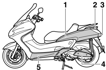
Left view
EAU10410
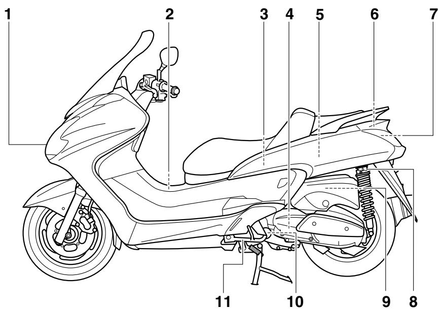
- Headlight (page 6-33)
- Fuel tank cap (page 3-14)
- Rear storage compartment (page 3-19)
- V-belt case air filter element (page 6-18)
- Owner's tool kit (page 6-1)
- Fuses (page 6-31)
-
Battery (page 6-30)
-
Shock absorber assembly spring preload adjusting ring (page 3-21)
- Air filter element (left) (page 6-18)
- Engine oil filter element (page 6-12)
11.Sidestand (page 3-21, 6-28)
Right view
EAU10420
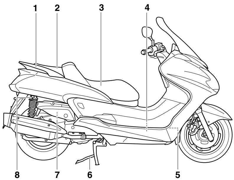
- Grab bar (page 5-2)
- Passenger seat (page 3-17)
- Rider seat (page 3-17)
- Coolant reservoir (page 6-16)
- Radiator
- Centerstand (page 6-28)
-
Air filter element (right) (page 6-18)
-
Shock absorber assembly spring preload adjusting ring (page 3-21)
Controls and instruments
EAU10430
- Rear brake lever (page 3-12)
- Left handlebar switches (page 3-10)
- Rear brake lock lever (page 3-12)
- Speedometer (page 3-5)
- Multi-function display (page 3-5)
- Tachometer (page 3-5)
-
Right handlebar switches (page 3-10)
-
Front brake lever (page 3-11)
- Throttle grip (page 6-20)
10.Front storage compartment B (page 3-19)
11.Main switch/steering lock (page 3-2)
12.Front storage compartment A (page 3-19)
EAU10976
Immobilizer system
- Code re-registering key (red bow)
- Standard keys (black bow)
This vehicle is equipped with an immobilizer system to help prevent theft by re-registering codes in the standard keys. This system consists of the following:
- a code re-registering key (with a red bow)
- two standard keys (with a black bow) that can be re-registered with new codes
- a transponder (which is installed in the code re-registering key)
- an immobilizer unit
-
an ECU
-
an immobilizer system indicator light (See page 3-3.)
The key with the red bow is used to register codes in each standard key. Since re-registering is a difficult process, take the vehicle along with all three keys to a Yamaha dealer to have them re-registered. Do not use the key with the red bow for driving. It should only be used for re-registering the standard keys. Always use a standard key for driving.
ECA11821
NOTICE
DO NOT LOSE THE CODE RE-REGISTERING KEY! CONTACT YOUR DEALER IMMEDIATELY IF IT IS LOST! If the code re-registering key is lost, registering new codes in the standard keys is impossible. The standard keys can still be used to start the vehicle, however if code re-registration is required (i.e., if a new standard key is made or all keys are lost) the entire immobilizer system must be replaced. Therefore, it is highly recommended to use either standard key and keep the code
re-registering key in a safe place.
- Do not submerge any key in water.
- Do not expose any key to excessively high temperatures.
- Do not place any key close to magnets (this includes, but not limited to, products such as speakers, etc.).
- Do not place items that transmit electrical signals close to any key.
- Do not place heavy items on any key.
- Do not grind any key or alter its shape.
- Do not disassemble the plastic part of any key.
- Do not put two keys of any immobilizer system on the same key ring.
- Keep the standard keys as well as keys of other immobilizer systems away from this vehicle's code re-registering key.
- Keep other immobilizer system keys away from the main switch
as they may cause signal interference.
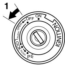
Main switch/steering lock
The main switch/steering lock controls the ignition and lighting systems, and is used to lock the steering.
TIP
Be sure to use the standard key (black bow) for regular use of the vehicle. To minimize the risk of losing the code re-registering key (red bow), keep it in a safe place and only use it for code re-registering.
EAU10471
EAU34121
ON
All electrical circuits are supplied with power; the meter lighting, taillight, license plate light and auxiliary lights
come on, and the engine can be started. The key cannot be removed.
TIP
The headlights come on automatically when the engine is started and stay on until the key is turned to "OFF" or the sidestand is moved down.
EAU10661
OFF
All electrical systems are off. The key can be removed.
EWA10061

WARNING
Never turn the key to "OFF" or "LOCK" while the vehicle is moving. Otherwise the electrical systems will be switched off, which may result in loss of control or an accident.
EAU10681
LOCK
The steering is locked, and all electrical systems are off. The key can be removed.
To lock the steering
- Turn the handlebars all the way to
the left.
- Push the key in from the "OFF" position, and then turn it to "LOCK" while still pushing it.
- Remove the key.
To unlock the steering
Push the key in, and then turn it to "OFF" while still pushing it.
EAU10941
The steering is locked, and the taillight, license plate light and auxiliary lights are on. The hazard lights and turn signal lights can be turned on, but all other electrical systems are off. The key can be removed.
The steering must be locked before the key can be turned to "P≤".
ECA11020
NOTICE
Do not use the parking position for an extended length of time, otherwise the battery may discharge.
EAU11004
Indicator and warning lights
- Turn signal indicator lights “ ” and “ ”
- High beam indicator light
- Immobilizer system indicator light
- Engine trouble warning light “ 心 ”
- Anti-lock Brake System (ABS) warning light “(®)”
EAU11030
Turn signal indicator lights “ ” and “ ”
The corresponding indicator light flashes when the turn signal switch is pushed to the left or right.
EAU11080
High beam indicator light “ O”
This indicator light comes on when the high beam of the headlight is
switched on.
EAU43023
Engine trouble warning light “H”
This warning light comes on if an electrical circuit monitoring the engine is not working correctly. If this occurs, have a Yamaha dealer check the self-diagnosis system.
The electrical circuit of the warning light can be checked by turning the key to "ON". The warning light should come on for a few seconds, and then go off. If the warning light does not come on initially when the key is turned to "ON", or if the warning light remains on, have a Yamaha dealer check the electrical circuit.
TIP
This warning light will come on when the key is turned to "ON" and the start switch is pushed, but this does not indicate a malfunction.
EAU48050
ABS warning light *
ECA10831
NOTICE
If the ABS warning light comes on or flashes while riding, the ABS may not work correctly. If this occurs, have a Yamaha dealer check the electrical circuit.
See page 3-13 for an explanation of the ABS.
The electrical circuit of the warning light can be checked by setting the engine stop switch to "O" and turning the key to "ON". The warning light should come on for a few seconds, and then go off. If the warning light does not come on initially when the key is turned to "ON", or if the warning light remains on, have a Yamaha dealer check the electrical circuit.
EWA11350
WARNING
When the ABS warning light comes on or flashes while riding, the brake system reverts to conventional braking. Therefore, be careful not to cause the wheel to lock during emergency braking.
TIP
The ABS warning light may come on while accelerating the engine with the scooter on its centerstand, but this does not indicate a malfunction.
nation of the self-diagnosis device.)
EAU38623
Immobilizer system indicator light
The electrical circuit of the indicator light can be checked by turning the key to "ON". The indicator light should come on for a few seconds, and then go off.
If the indicator light does not come on initially when the key is turned to "ON", or if the indicator light remains on, have a Yamaha dealer check the electrical circuit.
When the key is turned to "OFF" and 30 seconds have passed, the indicator light will start flashing indicating the immobilizer system is enabled. After 24 hours have passed, the indicator light will stop flashing, however the immobilizer system is still enabled.
This model is also equipped with a self-diagnosis device for the immobilizer system. (See page 3-8 for an expla
EAU11601
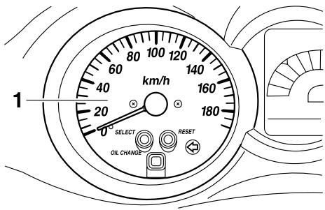
Speedometer
1. Speedometer
The speedometer shows the riding speed.
When the key is turned to "ON", the speedometer needle will sweep once across the speed range and then return to zero in order to test the electrical circuit.
EAU11872
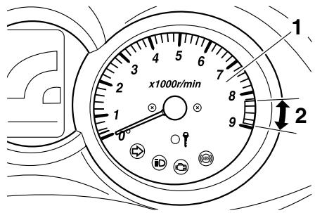
Tachometer
- Tachometer
- Tachometer red zone
The electric tachometer allows the rider to monitor the engine speed and keep it within the ideal power range.
When the key is turned to "ON", the tachometer needle will sweep once across the r/min range and then return to zero r/min in order to test the electrical circuit.
ECA10031
NOTICE
Do not operate the engine in the tachometer red zone.
Red zone: 8250 r/min and above
EAU3413A
EWA12312
Multi-function display

WARNING
Be sure to stop the vehicle before making any setting changes to the multi-function display. Changing settings while riding can distract the operator and increase the risk of an accident.
- Clock/ambient temperature display
- Coolant temperature meter
- Fuel meter
- Odometer/tripmeters
- "SELECT" button
- "RESET" button
- V-belt replacement indicator "V-BELT"
- Fuel level warning indicator "1"
- Coolant temperature warning indicator
- Oil change indicator "OIL"
The multi-function display is equipped with the following:
a fuel meter
- a coolant temperature meter
- an odometer
- two trip meters (which show the distance traveled since they were last set to zero)
- a fuel reserve tripmeter (which shows the distance traveled since the bottom segment of the fuel meter and fuel level warning indicator started flashing)
a self-diagnosis device
- a clock
- an ambient temperature display
- an oil change indicator
- a V-belt replacement indicator
TIP
- Be sure to turn the key to "ON" before using the "SELECT" and "RESET" buttons.
- When the key is turned to "ON", all of the display segments of the multi-function display will appear one after the other and then disappear, in order to test the electrical circuit.
Odometer and tripmeter modes
Pushing the "SELECT" button switches the display between the odometer mode "Odo" and the tripmeter modes "Trip" in the following order:
Odo Trip (top) Trip (bottom) Odo
When approximately 2.8 L (0.74 US gal, 0.62 Imp.gal) of fuel remains in the fuel tank, the bottom segment of the fuel meter and fuel level warning indicator will start flashing, and the display will
automatically change to the fuel reserve tripmeter mode "Trip F" and start counting the distance traveled from that point. In that case, pushing the "SELECT" button switches the display between the various tripmeter and odometer modes in the following order:
Trip F Trip (top) Trip (bottom) Odo Trip F
1. Fuel reserve tripmeter
To reset a tripmeter, select it by pushing the "SELECT" button until "Trip" or "Trip F" begins flashing ("Trip" or "Trip F" will only flash for five seconds). While "Trip" or "Trip F" is flashing, push the "RESET" button for at least one second. If you do not reset the fuel reserve tripmeter manually, it will reset it-
INSTRUMENT AND CONTROL FUNCTIONS
self automatically and the display will return to the prior mode after refueling and traveling 5km (3 mi).
TIP
The display cannot be changed back to "Trip F" after pushing the "RESET" button.
Fuel meter
With the key in the "ON" position, the fuel meter indicates the amount of fuel in the fuel tank. The display segments of the fuel meter disappear towards "E" (Empty) as the fuel level decreases. When the fuel level reaches the bottom segment near "E", the fuel level warning indicator and the bottom segment will flash. Refuel as soon as possible.
Coolant temperature meter
With the key in the "ON" position, the coolant temperature meter indicates the temperature of the coolant. The coolant temperature varies with changes in the weather and engine load. If the top segment and coolant temperature warning indicator flash, stop the vehicle and let the engine cool. (See
page 6-37.)
ECA10021
NOTICE
Do not continue to operate the engine if it is overheating.
Oil change indicator "OIL"
This indicator flashes at the initial 1000 km (600 mi), then at 5000 km (3000 mi) and every 5000 km (3000 mi) thereafter to indicate that the engine oil should be changed.
After changing the engine oil, reset the oil change indicator. (See page 6-12.) If the engine oil is changed before the oil change indicator comes on (i.e. before the periodic oil change interval has been reached), the indicator must be
reset after the oil change for the next periodic oil change to be indicated at the correct time. (See page 6-12.)
The electrical circuit of the indicator can be checked according to the following procedure.
- Set the engine stop switch to "O" and turn the key to "ON".
- Check that the indicator comes on for a few seconds and then goes off.
- If the indicator does not come on, have a Yamaha dealer check the electrical circuit.
TIP
The oil change indicator may flash when the engine is revved with the scooter on the centerstand, but this does not indicate a malfunction.
V-belt replacement indicator "V-BELT"
This indicator flashes every 20000 km (12500 mi) when the V-belt needs to be replaced.
The electrical circuit of the indicator can be checked according to the following procedure.
- Turn the key to "ON" and make sure that the engine stop switch is set to "O".
- If the indicator does not come on, have a Yamaha dealer check the electrical circuit.
Self-diagnosis device
This model is equipped with a self-diagnosis device for various electrical circuits.
If a problem is detected in any of those circuits, the multi-function display will indicate an error code.
If the multi-function display indicates an error code, note the code number, and then have a Yamaha dealer check the vehicle.
ECA11790
NOTICE
If the multi-function display indicates an error code, the vehicle should be checked as soon as possible in order to avoid engine damage.
The self-diagnosis device also detects problems in the immobilizer system circuits.
If a problem is detected in the immobilizer system circuits, the immobilizer system indicator light will flash and the multi-function display will indicate an error code when the key is turned to "ON".
TIP
If the multi-function display indicates error code 52, this could be caused by transponder interference. If this error appears, try the following.

-
Error code display
-
Use the code re-registering key to start the engine.
TIP
Make sure there are no other immobilizer keys close to the main switch, and
do not keep more than one immobilizer key on the same key ring! Immobilizer system keys may cause signal interference, which may prevent the engine from starting.
- If the engine starts, turn it off, and try starting the engine with the standard keys.
- If one or both of the standard keys do not start the engine, take the vehicle, the code re-registering key and both standard keys to a Yamaha dealer and have the standard keys re-registered.
If the multi-function display indicates any error codes, note the code number, and then have a Yamaha dealer check the vehicle.
Clock mode
To set the clock:
- Push the "SELECT" button and "RESET" button together for at least two seconds.
-
When the hour digits start flashing, push the "RESET" button to set the hours.
-
Push the "SELECT" button, and the minute digits will start flashing.
- Push the "RESET" button to set the minutes.
- Push the "SELECT" button and then release it to start the clock. Pushing the "SELECT" button for at least two seconds switches the clock display to the ambient temperature display.
Ambient temperature display
This display shows the ambient temperature from -10^ to 50^ in 1^ increments. The temperature displayed may vary from the ambient temperature. Pushing the "SELECT" button for at least two seconds switches the ambient temperature display to the clock display.
TIP
- If the ambient temperature falls below -10^ , a lower temperature than -10^ will not be displayed.
- If the ambient temperature climbs above 50^ , a higher temperature than 50^ will not be displayed.
The accuracy of the temperature
reading may be affected when riding slowly (approximately under 20 km/h (12.5 mi/h)) or when stopped at traffic signals, railroad crossings, etc.
EAU12331
Anti-theft alarm (optional)
This model can be equipped with an optional anti-theft alarm by a Yamaha dealer. Contact a Yamaha dealer for more information.
EAU12348 Handlebar switches Left
- Pass switch "PASS"
- Dimmer switch “ O/ O”
- Turn signal switch /
- Horn switch “▶”
Right
- Engine stop switch /
- Hazard switch “ ”
- Start switch ()
EAU12360
Pass switch "PASS"
Press this switch to flash the headlight.
EAU12400
Dimmer switch “ 0 / 0 ”
Set this switch to “ ” for the high beam and to “ ” for the low beam.
EAU12460
Turn signal switch 一 / 一
To signal a right-hand turn, push this switch to “ ”. To signal a left-hand turn, push this switch to “ ”. When released, the switch returns to the center
position. To cancel the turn signal lights, push the switch in after it has returned to the center position.
EAU12500
Horn switch “▶”
Press this switch to sound the horn.
EAU12660
Engine stop switch “O/×”
Set this switch to "O" before starting the engine. Set this switch to "X" to stop the engine in case of an emergency, such as when the vehicle overturns or when the throttle cable is stuck.
EAU12721
Start switch 空
With the sidestand up, push this switch while applying the front or rear brake to crank the engine with the starter. See page 5-1 for starting instructions prior to starting the engine.
EAU42340
The engine trouble warning light and ABS warning light will come on when the key is turned to "ON" and the start switch is pushed, but this does not indi
cate a malfunction.
EAU12733
Hazard switch “ ”
With the key in the "ON" or P ≤ position, use this switch to turn on the hazard lights (simultaneous flashing of all turn signal lights).
The hazard lights are used in case of an emergency or to warn other drivers when your vehicle is stopped where it might be a traffic hazard.
ECA10061
NOTICE
Do not use the hazard lights for an extended length of time with the engine not running, otherwise the battery may discharge.
Front brake lever
- Front brake lever
- Brake lever position adjusting dial
- “ ”mark
- Distance between brake lever and handlebar grip
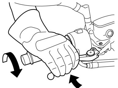
The front brake lever is located at the right handlebar grip. To apply the front brake, pull this lever toward the handlebar grip.
The front brake lever is equipped with a position adjusting dial. To adjust the distance between the front brake lever and the handlebar grip, turn the adjusting dial while holding the front brake lever pushed away from the handlebar grip. Make sure that the appropriate setting on the adjusting dial is aligned
EAU44910
with the “ ” mark on the front brake lever.
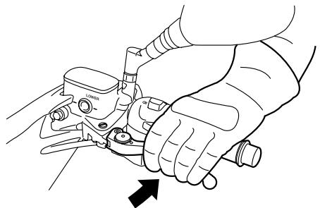
Rear brake lever
EAU44921
with the “ ” mark on the rear brake lever.
- Rear brake lever
- Brake lever position adjusting dial
- “ ” mark
- Distance between brake lever and handlebar grip
The rear brake lever is located at the left handlebar grip. To apply the rear brake, pull this lever toward the handlebar grip.
The rear brake lever is equipped with a position adjusting dial. To adjust the distance between the rear brake lever and the handlebar grip, turn the adjusting dial while holding the rear brake lever pushed away from the handlebar grip. Make sure that the appropriate setting on the adjusting dial is aligned
EAU12962
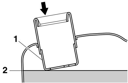
Rear brake lock lever
- Rear brake lock lever
This vehicle is equipped with a rear brake lock lever to prevent the rear wheel from moving while stopped at traffic signals, railroad crossings, etc.
To lock the rear wheel
Push the rear brake lock lever to the left until it snaps into place.
To unlock the rear wheel
Push the rear brake lock lever back to the original position.
TIP
- Be sure to check that the rear wheel does not move when the
rear brake lock lever is applied.
- To provide secure locking of the rear wheel, apply the rear brake lever first before moving the rear brake lock lever to the left.
EWA12361
WARNING
Never move the rear brake lock lever to the left while the vehicle is moving, otherwise loss of control or an accident may result. Make sure that the vehicle is stopped before moving the rear brake lock lever to the left.
EAU48040
ABS
The Yamaha ABS (Anti-lock Brake System) features a dual electronic control system, which acts on the front and rear brakes independently. The ABS securely controls wheel lockup during emergency braking on changing road surfaces and under various weather conditions, thereby maximizing tire adhesion and performance while providing a smooth braking action. The ABS is monitored by an ECU, which will have recourse to manual braking if a malfunction occurs.
EWA10090
WARNING
- The ABS performs best on long braking distances.
- On certain (rough or gravel) roads, the braking distance may be longer with than without the ABS. Therefore, always keep a sufficient distance to the vehicle ahead to match the riding speed.
TIP
The ABS performs a self-diagno
sis test for a few seconds each time the vehicle first starts off after the main switch was turned on. During this test, a "clicking" noise can be heard from the front of the vehicle, and if either brake lever is even slightly applied, a vibration can be felt at the lever, but these do not indicate a malfunction.
- When the ABS is activated, the brakes are operated in the usual way. A pulsating action may be felt at the brake levers, but this does not indicate a malfunction.
- This ABS has a test mode which allows the owner to experience the pulsating at the brake levers when the ABS is operating. However, special tools are required, so please consult your Yamaha dealer when performing this test.
ECA16120
NOTICE
Keep any type of magnets (including magnetic pick-up tools, magnetic screwdrivers, etc.) away from the front and rear wheel hubs, otherwise the magnetic rotors equipped in the
wheel hubs may be damaged, resulting in improper performance of the ABS system.
1. Front wheel hub
1. Rear wheel hub
EAU13163
Fuel tank cap
To open the fuel tank cap
- Open the lid by sliding the lever forward, and then pull the lever up.
- Lid
- Opening lever
- Insert the key into the lock and turn it clockwise. The lock will be released and the fuel tank cap can be removed.
1. Fuel tank cap
To install the fuel tank cap
- Align the match marks, insert the fuel tank cap into the tank opening, and then push down on the cap.
- Match marks
- Turn the key counterclockwise to
the original position, and then remove it.
- Close the lid.

WARNING
EWA11121
Be sure that the fuel tank cap is properly installed and locked before riding the scooter. Leaking fuel is a fire hazard.
EAU13221
Fuel
Make sure there is sufficient gasoline in the tank.
EWA10881

WARNING
Gasoline and gasoline vapors are extremely flammable. To avoid fires and explosions and to reduce the risk of injury when refueling, follow these instructions.
-
Before refueling, turn off the engine and be sure that no one is sitting on the vehicle. Never refuel while smoking, or while in the vicinity of sparks, open flames, or other sources of ignition such as the pilot lights of water heaters and clothes dryers.
-
Do not overfill the fuel tank. When refueling, be sure to insert the pump nozzle into the fuel tank filler hole. Stop filling when the fuel reaches the bottom of the filler tube. Because fuel expands when it heats up, heat from the engine or the sun can cause fuel to spill out of the fuel tank.
- Fuel tank filler tube
- Fuel level
- Wipe up any spilled fuel immediately. NOTICE: Immediately wipe off spilled fuel with a clean, dry, soft cloth, since fuel may deteriorate painted surfaces or plastic parts.[ECA10071]
- Be sure to securely close the fuel tank cap.
EWA15151

WARNING
Gasoline is poisonous and can cause injury or death. Handle gasoline with care. Never siphon gasoline by mouth. If you should swallow some gasoline or inhale a lot of gasoline vapor, or get some gasoline in
your eyes, see your doctor immediately. If gasoline spills on your skin, wash with soap and water. If gasoline spills on your clothing, change your clothes.
EAU33520
Recommended fuel: REGULAR UNLEADED GASOLINE ONLY
Fuel tank capacity: 14.0 L (3.70 US gal, 3.08 Imp.gal)
ECA11400
NOTICE
Use only unleaded gasoline. The use of leaded gasoline will cause severe damage to internal engine parts, such as the valves and piston rings, as well as to the exhaust system.
Your Yamaha engine has been designed to use regular unleaded gasoline with a research octane number of 91 or higher. If knocking (or pinging) occurs, use a gasoline of a different brand or premium unleaded fuel. Use of unleaded fuel will extend spark plug life
and reduce maintenance costs.
EAU13445
Catalytic converters
This vehicle is equipped with catalytic converters in the exhaust system.
EWA10862
WARNING
The exhaust system is hot after operation. To prevent a fire hazard or burns:
- Do not park the vehicle near possible fire hazards such as grass or other materials that easily burn.
- Park the vehicle in a place where pedestrians or children are not likely to touch the hot exhaust system.
- Make sure that the exhaust system has cooled down before doing any maintenance work.
- Do not allow the engine to idle more than a few minutes. Long idling can cause a build-up of heat.
ECA10701
NOTICE
Use only unleaded gasoline. The use of leaded gasoline will cause unre
pairable damage to the catalytic converter.
EAU34140
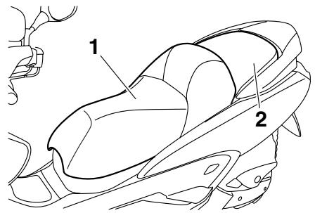
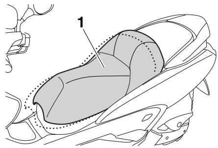
Seats
- Rider seat
- Passenger seat
Rider seat
To open the rider seat
- Place the scooter on the centerstand.
- Insert the key into the main switch, and then turn it counterclockwise.
- Open.
TIP
Do not push inward when turning the key.
- Fold the rider seat up.
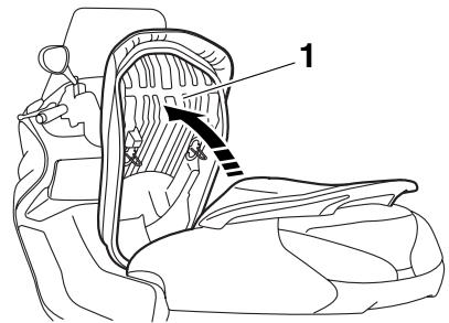
- Rider seat
To close the rider seat
- Fold the rider seat down, and then push it down to lock it in place.
- Remove the key from the main switch if the scooter will be left unattended.
TIP
Make sure that the rider seat is properly secured before riding.
Passenger seat
To remove the passenger seat
- Open the rider seat.
- Remove the bolt, and then pull the passenger seat forward.
- Passenger seat
- Bolt
To install the passenger seat
- Insert the projections on the passenger seat into the holders as shown, place the passenger seat in the original position, and then install the bolt.
- Passenger seat
-
Seat holder
-
Close the rider seat.
TIP
Make sure that the passenger seat is properly secured before riding.
EAU34150
Adjusting the rider seat
- Rider seat
The rider seat can be adjusted as follows to change the riding position.
- Open the rider seat. (See page 3-17.)
- Remove the bolts.
-
Bolt
-
Slide the rider seat forward or backward to the desired position.
- Install bolts and securely tighten them.
- Close the rider seat.
EAU14494
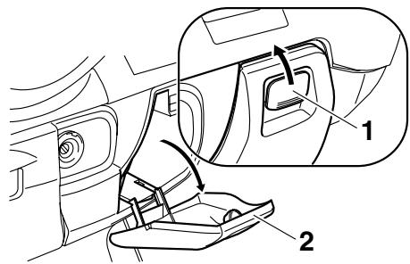
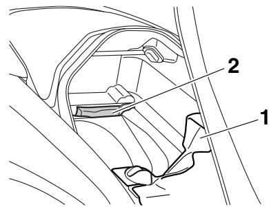
Storage compartments
Front storage compartment A
To open the storage compartment when it is locked, insert the key in the lock, turn it counterclockwise, and then grasp the lock while pushing the button in.
To open the storage compartment when it is unlocked, simply grasp the lock while pushing the button in.
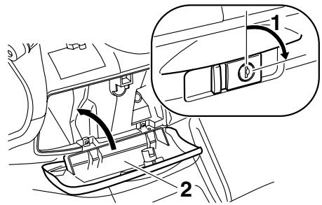
- Lock.
- Lid
- Open.
- Button
- Lid
To lock the storage compartment, push the lid into the original position, insert the key in the lock, turn it clockwise, and then remove it.
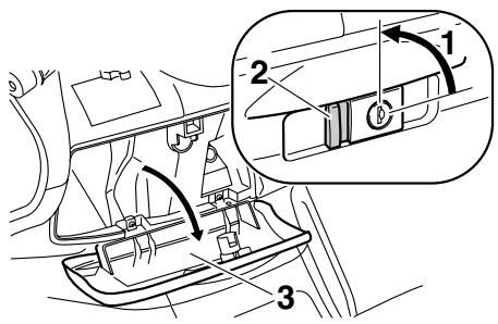
Front storage compartment B
To open the storage compartment, slide the lever up, and then pull on the lever.
- Storage compartment opening lever
- Lid
To close the storage compartment, push the lid into the original position. WARNING! Do not store heavy items in this compartment.[EWA11161]
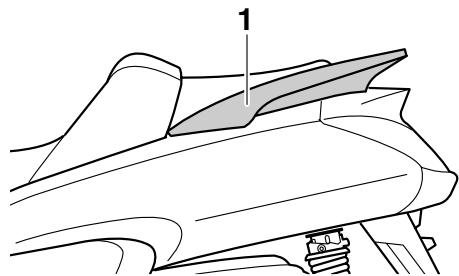
Rear storage compartment
Two helmets can be stored in the storage compartment under the seats. (See page 3-17.)
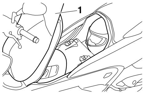
1. Rider seat
ECA10080
NOTICE
Keep the following points in mind when using the storage compartment.
- Since the storage compartment accumulates heat when exposed to the sun, do not store
anything susceptible to heat inside it.
- To avoid humidity from spreading through the storage compartment, wrap wet articles in a plastic bag before storing them in the compartment.
- Since the storage compartment may get wet while the scooter is being washed, wrap any articles stored in the compartment in a plastic bag.
- Do not keep anything valuable or breakable in the storage compartment.
ECA11100
NOTICE
Do not leave the rider seat open for an extended period of time, otherwise the light may cause the battery to discharge.
EWA11171
WARNING
Do not exceed the following loading limits:
-
Front storage compartment A: 2 kg (4 lb)
-
Rear storage compartment: 5 kg (11 lb)
Maximum load for the vehicle: 185 kg (408 lb)
EAU14891
Adjusting the shock absorber assemblies
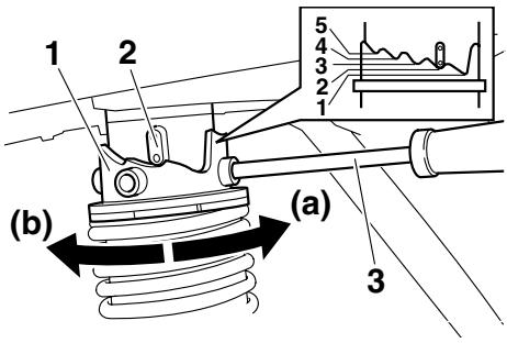
- Spring preload adjusting ring
- Position indicator
- Spring preload adjusting tool
Each shock absorber assembly is equipped with a spring preload adjusting ring.
ECA10101
NOTICE
To avoid damaging the mechanism, do not attempt to turn beyond the maximum or minimum settings.
EWA10210
WARNING
Always adjust both shock absorber assemblies equally, otherwise poor
handling and loss of stability may result.
Adjust the spring preload as follows. To increase the spring preload and thereby harden the suspension, turn the adjusting ring on each shock absorber assembly in direction (a). To decrease the spring preload and thereby soften the suspension, turn the adjusting ring on each shock absorber assembly in direction (b).
- Align the appropriate notch in the adjusting ring with the position indicator on the shock absorber.
- Use the spring preload adjusting tool included in the owner's tool kit to make this adjustment.
Spring preload setting:
Minimum (soft):
1
Standard:
2
Maximum (hard):
5
EAU15301
Sidestand
The sidestand is located on the left side of the frame. Raise the sidestand or lower it with your foot while holding the vehicle upright.
TIP
The built-in sidestand switch is part of the ignition circuit cut-off system, which cuts the ignition in certain situations. (See further down for an explanation of the ignition circuit cut-off system.)
EWA10240

WARNING
The vehicle must not be ridden with the sidestand down, or if the sidestand cannot be properly moved up (or does not stay up), otherwise the sidestand could contact the ground and distract the operator, resulting in a possible loss of control. Yamaha's ignition circuit cut-off system has been designed to assist the operator in fulfilling the responsibility of raising the sidestand before starting off. Therefore, check this system regularly as described below and have a Yamaha dealer re
pair it if it does not function properly.
EAU45051
Ignition circuit cut-off system
The ignition circuit cut-off system (comprising the sidestand switch and brake light switches) has the following functions.
- It prevents starting when the side-stand is up, but neither brake is applied.
- It prevents starting when either brake is applied, but the sidestand is still down.
- It cuts the running engine when the sidestand is moved down.
Periodically check the operation of the ignition circuit cut-off system according to the following procedure.
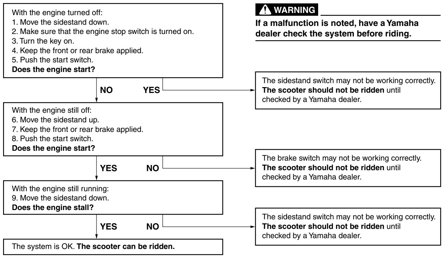
EAU15596
Inspect your vehicle each time you use it to make sure the vehicle is in safe operating condition. Always follow the inspection and maintenance procedures and schedules described in the Owner's Manual.
EWA11151

WARNING
Failure to inspect or maintain the vehicle properly increases the possibility of an accident or equipment damage. Do not operate the vehicle if you find any problem. If a problem cannot be corrected by the procedures provided in this manual, have the vehicle inspected by a Yamaha dealer.
Before using this vehicle, check the following points:
| ITEM | CHECKS | PAGE |
| Fuel | ·Check fuel level in fuel tank. ·Refuel if necessary. ·Check fuel line for leakage. | 3-15 |
| Engine oil | ·Check oil level in engine. ·If necessary, add recommended oil to specified level. ·Check vehicle for oil leakage. | 6-12 |
| Final transmission oil | ·Check vehicle for oil leakage. | 6-15 |
| Coolant | ·Check coolant level in reservoir. ·If necessary, add recommended coolant to specified level. ·Check cooling system for leakage. | 6-16 |
| Front brake | ·Check operation. ·If soft or spongy, have Yamaha dealer bleed hydraulic system. ·Check brake pads for wear. ·Replace if necessary. ·Check fluid level in reservoir. ·If necessary, add recommended brake fluid to specified level. ·Check hydraulic system for leakage. | 6-23, 6-25 |
| ITEM | CHECKS | PAGE |
| Rear brake | ·Check operation. ·If soft or spongy, have Yamaha dealer bleed hydraulic system. ·Check brake pads for wear. ·Replace if necessary. ·Check fluid level in reservoir. ·If necessary, add recommended brake fluid to specified level. ·Check hydraulic system for leakage. | 6-23, 6-25 |
| Throttle grip | ·Make sure that operation is smooth. ·Check cable free play. ·If necessary, have Yamaha dealer adjust cable free play and lubricate cable and grip housing. | 6-20, 6-27 |
| Wheels and tires | ·Check for damage. ·Check tire condition and tread depth. ·Check air pressure. ·Correct if necessary. | 6-21, 6-23 |
| Brake levers | ·Make sure that operation is smooth. ·Lubricate lever pivoting points if necessary. | 6-27 |
| Centerstand, sidestand | ·Make sure that operation is smooth. ·Lubricate pivots if necessary. | 6-28 |
| Chassis fasteners | ·Make sure that all nuts, bolts and screws are properly tightened. ·Tighten if necessary. | — |
| Instruments, lights, signals and switches | ·Check operation. ·Correct if necessary. | — |
| Sidestand switch | ·Check operation of ignition circuit cut-off system. ·If system is not working correctly, have Yamaha dealer check vehicle. | 3-21 |
EAU15951
Read the Owner's Manual carefully to become familiar with all controls. If there is a control or function you do not understand, ask your Yamaha dealer.
EWA10271

WARNING
Failure to familiarize yourself with the controls can lead to loss of control, which could cause an accident or injury.
EAU48020
TIP
This model is equipped with a lean angle sensor to stop the engine in case of a turnover. In this case, the multi-function display indicates error code 30, but this is not a malfunction. Turn the key to "OFF" and then to "ON" to clear the error code. Failing to do so will prevent the engine from starting even though the engine will crank when pushing the start switch.
EAU36512
Starting the engine
ECA10250
NOTICE
See page 5-4 for engine break-in instructions prior to operating the vehicle for the first time.
In order for the ignition circuit cut-off system to enable starting, the side-stand must be up.
See page 3-22 for more information.
- Turn the key to "ON" and make sure that the engine stop switch is set to "O".
The following warning lights, indicator light and indicators should come on for a few seconds, then go off.
Engine trouble warning light
- ABS warning light (for ABS models)
- Immobilizer system indicator light
V-belt replacement indicator
- Oil change indicator
ECA15022
NOTICE
If a warning light, indicator light or indicator does not go off, see pages
3-3, 3-7, 3-8 or 3-5 for the corresponding warning light, indicator light or indicator circuit check.
- Close the throttle completely.
- Start the engine by pushing the start switch while applying the front or rear brake. NOTICE: For maximum engine life, never accelerate hard when the engine is cold![ECA11041]
If the engine does not start, release the start switch, wait a few seconds, and then try again. Each starting attempt should be as short as possible to preserve the battery. Do not crank the engine more than 10 seconds on any one attempt.
EAU45091
Starting off
- While pulling the rear brake lever with your left hand and holding the grab bar with your right hand, push the scooter off the centerstand.
-
Grab bar
-
Sit astride the seat, and then adjust the rear view mirrors.
- Switch the turn signals on.
- Check for oncoming traffic, and then slowly turn the throttle grip (on the right) in order to take off.
- Switch the turn signals off.
EAU16780
Acceleration and deceleration
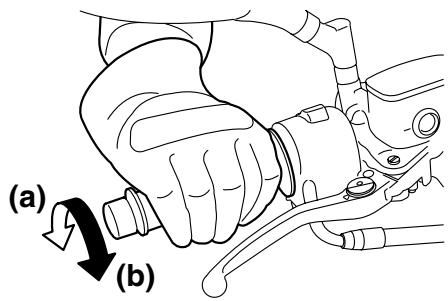
The speed can be adjusted by opening and closing the throttle. To increase the speed, turn the throttle grip in direction (a). To reduce the speed, turn the throttle grip in direction (b).
EAU16793
Braking
EWA10300
WARNING
- Avoid braking hard or suddenly (especially when leaning over to one side), otherwise the scooter may skid or overturn.
- Railroad crossings, streetcar rails, iron plates on road construction sites, and manhole covers become extremely slippery when wet. Therefore, slow down when approaching such areas and cross them with caution.
- Keep in mind that braking on a wet road is much more difficult.
-
Ride slowly down a hill, as braking downhill can be very difficult.
-
Close the throttle completely.
- Apply both front and rear brakes simultaneously while gradually increasing the pressure.
Front
Rear
EAU16820
Tips for reducing fuel consumption
Fuel consumption depends largely on your riding style. Consider the following tips to reduce fuel consumption:
- Avoid high engine speeds during acceleration.
- Avoid high engine speeds with no load on the engine.
- Turn the engine off instead of letting it idle for an extended length of time (e.g., in traffic jams, at traffic lights or at railroad crossings).
EAU16841
Engine break-in
There is never a more important period in the life of your engine than the period between 0 and 1600km (1000 mi). For this reason, you should read the following material carefully.
Since the engine is brand new, do not put an excessive load on it for the first 1600km (1000 mi). The various parts in the engine wear and polish themselves to the correct operating clearances. During this period, prolonged full-throttle operation or any condition that might result in engine overheating must be avoided.
EAU34321
0-1000 km (0-600 mi)
Avoid prolonged operation above 4000 r/min. NOTICE: After 1000 km (600 mi) of operation, be sure to replace the engine oil, final transmission oil and the oil filter element.[ECA12931]
1000-1600 km (600-1000 mi)
Avoid prolonged operation above 6000 r/min.
1600 km (1000 mi) and beyond
The vehicle can now be operated normally.
ECA10310
NOTICE
- Keep the engine speed out of the tachometer red zone.
- If any engine trouble should occur during the engine break-in period, immediately have a Yamaha dealer check the vehicle.
EAU17213
Parking
When parking, stop the engine, and then remove the key from the main switch.
WARNING
EWA10311
- Since the engine and exhaust system can become very hot, park in a place where pedestrians or children are not likely to touch them and be burned.
- Do not park on a slope or on soft ground, otherwise the vehicle may overturn, increasing the risk of a fuel leak and fire.
- Do not park near grass or other flammable materials which might catch fire.
EAU17241
Periodic inspection, adjustment, and lubrication will keep your vehicle in the safest and most efficient condition possible. Safety is an obligation of the vehicle owner/operator. The most important points of vehicle inspection, adjustment, and lubrication are explained on the following pages.
The intervals given in the periodic maintenance and lubrication chart should be simply considered as a general guide under normal riding conditions. However, depending on the weather, terrain, geographical location, and individual use, the maintenance intervals may need to be shortened.
EWA10321
WARNING
Failure to properly maintain the vehicle or performing maintenance activities incorrectly may increase your risk of injury or death during service or while using the vehicle. If you are not familiar with vehicle service, have a Yamaha dealer perform service.
EWA15121
WARNING
Turn off the engine when performing maintenance unless otherwise specified.
- A running engine has moving parts that can catch on body parts or clothing and electrical parts that can cause shocks or fires.
- Running the engine while servicing can lead to eye injury, burns, fire, or carbon monoxide poisoning – possibly leading to death. See page 1-1 for more information about carbon monoxide.
EAU17502
Owner's tool kit
- Storage compartment mat
- Owner's tool kit
The owner's tool kit is located inside the rear storage compartment. (See page 3-19.)
Pull up the storage compartment mat, and then remove the owner's tool kit. The service information included in this manual and the tools provided in the owner's tool kit are intended to assist you in the performance of preventive maintenance and minor repairs. However, additional tools such as a torque wrench may be necessary to perform certain maintenance work correctly.
PERIODIC MAINTENANCE AND ADJUSTMENT
TIP
If you do not have the tools or experience required for a particular job, have a Yamaha dealer perform it for you.
EAU46861
TIP
- The annual checks must be performed every year, except if a kilometer-based maintenance, or for the UK, a mileage-based maintenance, is performed instead.
- From 50000 km (30000 mi), repeat the maintenance intervals starting from 10000 km (6000 mi).
- Items marked with an asterisk should be performed by a Yamaha dealer as they require special tools, data and technical skills.
EAU46910
Periodic maintenance chart for the emission control system
| NO. | ITEM | CHECK OR MAINTENANCE JOB | ODOMETER READING | ANNUAL CHECK | |||||
| 1000 km(600 mi) | 10000 km(6000 mi) | 20000 km(12000 mi) | 30000 km(18000 mi) | 40000 km(24000 mi) | |||||
| 1 | * | Fuel line | · Check fuel hoses for cracks or damage. | ✓ | ✓ | ✓ | ✓ | ✓ | |
| 2 | Spark plug | · Check condition. · Clean and regap. | ✓ | ✓ | |||||
| · Replace. | ✓ | ✓ | |||||||
| 3 | * | Valves | · Check valve clearance. · Adjust. | Every 40000 km (24000 mi) | |||||
| 4 | * | Fuel injection | · Check engine idle speed. | ✓ | ✓ | ✓ | ✓ | ✓ | ✓ |
| 5 | * | Air induction system | · Check the air cut-off valve, reed valve, and hose for damage. · Replace any damaged parts if necessary. | ✓ | ✓ | ✓ | ✓ | ✓ | |
EAU1770C
General maintenance and lubrication chart
| NO. | ITEM | CHECK OR MAINTENANCE JOB | ODOMETER READING | ANNUAL CHECK | |||||
| 1000 km(600 mi) | 10000 km(6000 mi) | 20000 km(12000 mi) | 30000 km(18000 mi) | 40000 km(24000 mi) | |||||
| 1 | Air filter elements | Replace. | ✓ | ✓ | |||||
| 2 | V-belt case air filter element | Clean. | ✓ | ✓ | ✓ | ✓ | |||
| 3 | * | Front brake | Check operation, fluid level and vehicle for fluid leakage. | ✓ | ✓ | ✓ | ✓ | ✓ | ✓ |
| Replace brake pads. | Whenever worn to the limit | ||||||||
| 4 | * | Rear brake | Check operation, fluid level and vehicle for fluid leakage. | ✓ | ✓ | ✓ | ✓ | ✓ | ✓ |
| Replace brake pads. | Whenever worn to the limit | ||||||||
| 5 | * | Brake hoses | Check for cracks or damage. | ✓ | ✓ | ✓ | ✓ | ✓ | |
| Replace. | Every 4 years | ||||||||
| 6 | Rear brake lock | Check operation. Adjust. | ✓ | ✓ | ✓ | ✓ | ✓ | ✓ | |
| 7 | * | Wheels | Check runout and for damage. | ✓ | ✓ | ✓ | ✓ | ||
| 8 | * | Tires | Check tread depth and for damage. Replace if necessary. Check air pressure. Correct if necessary. | ✓ | ✓ | ✓ | ✓ | ✓ | |
| 9 | * | Wheel bearings | Check bearing for looseness or damage. | ✓ | ✓ | ✓ | ✓ | ||
| 10 | * | Steering bearings | Check bearing play and steering for roughness. | ✓ | ✓ | ✓ | ✓ | ✓ | |
| Lubricate with lithium-soap-based grease. | Every 20000 km (12000 mi) | ||||||||
| 11 | * | Chassis fasteners | Make sure that all nuts, bolts and screws are properly tightened. | ✓ | ✓ | ✓ | ✓ | ✓ | |
| 12 | Front brake lever pivot shaft | • Lubricate with silicone grease. | ✓ | ✓ | ✓ | ✓ | ✓ | ||
| 13 | Rear brake lever pivot shaft | • Lubricate with silicone grease. | ✓ | ✓ | ✓ | ✓ | ✓ | ||
| 14 | Sidestand, center-stand | • Check operation. • Lubricate. | ✓ | ✓ | ✓ | ✓ | ✓ | ||
| 15 | * | Sidestand switch | • Check operation. | ✓ | ✓ | ✓ | ✓ | ✓ | ✓ |
| 16 | * | Front fork | • Check operation and for oil leakage. | ✓ | ✓ | ✓ | ✓ | ||
| 17 | * | Shock absorber assemblies | • Check operation and shock absorbers for oil leakage. | ✓ | ✓ | ✓ | ✓ | ||
| 18 | Engine oil | • Change. (See pages 3-5 and 6-12.) | ✓ | When the oil change indicator flashes | |||||
| • Check oil level and vehicle for oil leakage. | Every 5000 km (3000 mi) | ✓ | |||||||
| 19 | Engine oil filter element | • Replace. | ✓ | ✓ | ✓ | ||||
| 20 | * | Cooling system | • Check coolant level and vehicle for coolant leakage. | ✓ | ✓ | ✓ | ✓ | ✓ | |
| • Change. | Every 3 years | ||||||||
| 21 | Final transmission oil | • Check vehicle for oil leakage. | ✓ | ✓ | ✓ | ||||
| • Change. | ✓ | ✓ | ✓ | ✓ | ✓ | ✓ | |||
| 22 | * | V-belt | • Replace. | When the V-belt replacement indicator flashes [every 20000 km (12000 mi)] | |||||
| 23 | * | Front and rear brake switches | • Check operation. | ✓ | ✓ | ✓ | ✓ | ✓ | ✓ |
| 24 | Moving parts and cables | • Lubricate. | ✓ | ✓ | ✓ | ✓ | ✓ | ||
PERIODIC MAINTENANCE AND ADJUSTMENT
| NO. | ITEM | CHECK OR MAINTENANCE JOB | ODOMETER READING | ANNUAL CHECK | |||||
| 1000 km (600 mi) | 10000 km (6000 mi) | 20000 km (12000 mi) | 30000 km (18000 mi) | 40000 km (24000 mi) | |||||
| 25 | * | Throttle grip hous- ing and cable | • Check operation and free play. • Adjust the throttle cable free play if necessary. • Lubricate the throttle grip housing and cable. | ✓ | ✓ | ✓ | ✓ | ✓ | |
| 26 | * | Lights, signals and switches | • Check operation. • Adjust headlight beam. | ✓ | ✓ | ✓ | ✓ | ✓ | ✓ |
EAU34491
TIP
-
Engine air filters and V-belt air filter
-
This model's engine air filters are equipped with disposable oil-coated paper elements, which must not be cleaned with compressed air to avoid damaging them.
-
The engine air filter elements need to be replaced and the V-belt air filter element needs to be serviced more frequently when riding in unusually wet or dusty areas.
-
Hydraulic brake service
-
Regularly check and, if necessary, correct the brake fluid level.
- Every two years replace the internal components of the brake master cylinders and calipers, and change the brake fluid.
- Replace the brake hoses every four years and if cracked or damaged.
EAU18712
Removing and installing cowlings and panels
The cowlings and panels shown need to be removed to perform some of the maintenance jobs described in this chapter. Refer to this section each time a cowling or panel needs to be removed and installed.
- Cowling C
- Cowling A
- Cowling B
- Panel A
- Cowling E
- Cowling D
EAU34282
Cowling A
To remove the cowling
- Open the rider seat. (See page 3-17.)
- Remove the quick fasteners in the rear storage compartment, and then pull the cowling off as shown.
TIP
The quick fastener is removed by pushing the center pin in with a screwdriver, and then pulling the fastener out.
- Quick fastener
- Cowling A
To install the cowling
- Place the cowling in the original position, and then install the quick fasteners.
TIP
To install the quick fastener, push the center pin out so that it will protrude from the fastener head, insert the fastener into the cowling, and then push the protruding pin in until it is flush with the fastener head.
- Close the rider seat.
Cowling B
To remove the cowling
- Remove the screws.
- Cowling B
- Screw
- Remove the cowling as shown.
- Cowling B
To install the cowling
Place the cowling in the original position, and then install the screws.
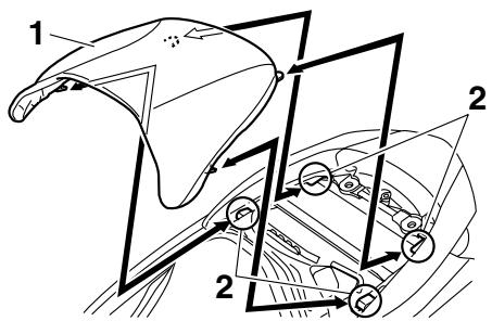
Cowlings C and D
To remove one of the cowlings
- Remove cowlings A and B.
- Remove the passenger seat. (See page 3-17.)
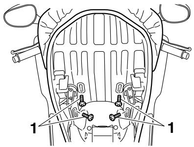
- Remove the grab bar by removing the grab bar bolts and collars.
- Grab bar bolt
- Collar
- Grab bar
- Remove the screw access cover by pulling it off.
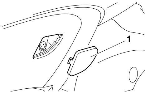
- Screw access cover
- Remove the screws, and then pull the cowling off.
- Screw
To install the cowling
- Place the cowling in the original position, and then install the screws.
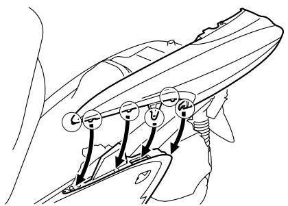
- Install the screw access cover by placing it in its original position.
- Install the grab bar by installing the collars and grab bar bolts.
Tightening torque:
Grab bar bolt:
23 Nm (2.3 m·kgf, 16.6 ft·lbf)
- Install the passenger seat.
- Install cowlings A and B.
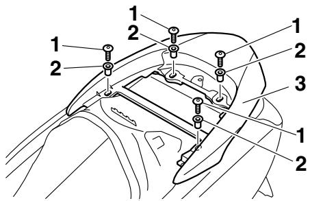
Cowling E
To remove the cowling
- Pull up the left floorboard mats as shown.
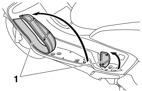
- Left floorboard mat
- Remove the cowling screws.
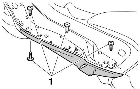
-
Screw
-
Pull the cowling down slightly, and then pull it outward as shown.
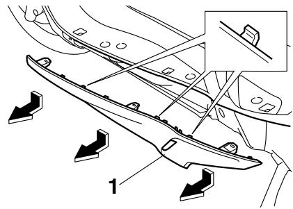
- Cowling E
To install the cowling
- Insert the projections on the cowling into the slots as shown, and then install the screws.
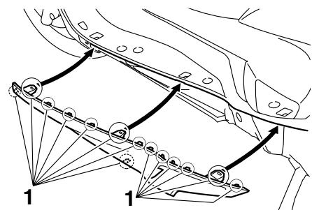
-
Projection
-
Place the left floorboard mats in the original position.
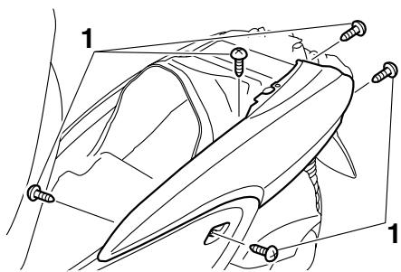
Panel A
To remove the panel
Remove the screws, and then pull the panel outward.
- Panel A
- Screw
To install the panel
Place the panel in the original position, and then install the screws.
- Screw
- Panel A
EAU34172
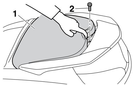
Checking the spark plug
The spark plug is an important engine component, which is easy to check. Since heat and deposits will cause any spark plug to slowly erode, the spark plug should be removed and checked in accordance with the periodic maintenance and lubrication chart. In addition, the condition of the spark plug can reveal the condition of the engine.
To remove the spark plug
- Open the rider seat. (See page 3-17.)
- Pull up the storage compartment mat, and then remove the spark plug cover by removing the screws.

- Storage compartment mat
- Spark plug cover
-
Screw
-
Remove the spark plug cap.
- Spark plug cap
- Remove the spark plug as shown, with the spark plug wrench included in the owner's tool kit.
- Spark plug wrench
To check the spark plug
- Check that the porcelain insulator around the center electrode of the spark plug is a medium-to-light tan (the ideal color when the vehicle is ridden normally).
TIP If the spark plug shows a distinctly different color, the engine could be operating improperly. Do not attempt to diagnose such problems yourself. Instead, have a Yamaha dealer check the vehicle.
- Check the spark plug for electrode erosion and excessive carbon or other deposits, and replace
it if necessary.
Specified spark plug: NGK/CR7E
To install the spark plug
- Measure the spark plug gap with a wire thickness gauge and, if necessary, adjust the gap to specification.
- Spark plug gap
Spark plug gap:
0.7-0.8 mm (0.028-0.031 in)
-
Clean the surface of the spark plug gasket and its mating surface, and then wipe off any grime from the spark plug threads.
-
Install the spark plug with the spark plug wrench, and then tighten it to the specified torque.
Tightening torque:
Spark plug:
12.5 Nm (1.25 m·kgf, 9 ft·lbf)
TIP
If a torque wrench is not available when installing a spark plug, a good estimate of the correct torque is 1/4 - 1/2 turn past finger tight. However, the spark plug should be tightened to the specified torque as soon as possible.
- Install the spark plug cap.
TIP
Make sure the spark plug wire is fastened in the clamp as shown.
- Spark plug cap
- Spark plug wire clamp
- Install the spark plug cover by installing the screws.
- Place the storage compartment mat in the original position.
- Close the rider seat.
EAU34184
Engine oil and oil filter element
The engine oil level should be checked before each ride. In addition, the oil must be changed and the oil filter element replaced at the intervals specified in the periodic maintenance and lubrication chart and when the oil change indicator comes on.
To check the engine oil level
- Place the vehicle on the centerstand. A slight tilt to the side can result in a false reading.
- Start the engine, warm it up for several minutes, and then turn it off.
- Wait a few minutes until the oil settles, remove the oil filler cap, wipe the dipstick clean, insert it back into the oil filler hole (without screwing it in), and then remove it again to check the oil level.
TIP
The engine oil should be between the minimum and maximum level marks.
- Engine oil filler cap
- Dipstick
- Maximum level mark
-
Minimum level mark
-
If the engine oil is below the minimum level mark, add sufficient oil of the recommended type to raise it to the correct level.
- Insert the dipstick into the oil filler hole, and then tighten the oil filler cap.
To change the engine oil (with or without oil filter element replacement)
-
Start the engine, warm it up for several minutes, and then turn it off.
-
Place an oil pan under the engine to collect the used oil.
- Remove the engine oil filler cap and the engine oil drain bolt to drain the oil from the crankcase.
- Engine oil drain bolt
- Check the washer for damage and replace it if necessary.
- Engine oil drain bolt
- Washer
TIP Skip steps 5-7 if the oil filter element is not being replaced.
- Remove the oil filter element cover by removing the bolts. NOTICE: When removing the oil filter element cover, the compression spring will fall out. Take care not to lose the compression spring.[ECA12911]
- Bolt
- Oil filter element cover
- Remove and replace the oil filter element and O-rings.
- Oil filter element cover
- O-ring
- Compression spring
-
Oil filter element
-
Install the compression spring and oil filter element cover by installing the bolts, then tightening them to the specified torque.
Tightening torque:
Oil filter element cover bolt:
10 Nm (1.0 m·kgf, 7.2 ft·lbf)
TIP
Make sure that the O-rings are properly seated.
- Install the washer and the engine oil drain bolt, and then tighten the drain bolt to the specified torque.
Tightening torque:
Engine oil drain bolt:
20 Nm (2.0 m·kgf, 14.5 ft·lbf)
TIP
Make sure that the washer is properly seated.
- Refill with the specified amount of the recommended engine oil, and then install and tighten the oil filler cap.
Recommended engine oil:
See page 8-1.
Oil quantity:
Without oil filter element replacement:
1.50 L (1.59 US qt, 1.32 Imp qt)
With oil filter element replacement:
1.70 L (1.80 US qt, 1.50 Imp qt)
TIP
Be sure to wipe off spilled oil on any parts after the engine and exhaust system have cooled down.
ECA11670
NOTICE
- Do not use oils with a diesel specification of "CD" or oils of a higher quality than specified. In addition, do not use oils labeled "ENERGY CONSERVING II" or higher.
-
Be sure no foreign material enters the crankcase.
-
Start the engine, and then let it idle for several minutes while checking it for oil leakage. If oil is leaking, immediately turn the engine off and check for the cause.
-
Reset the oil change indicator according to the following procedure.
To reset the oil change indicator
- Turn the key to "ON".
- Hold the "OIL CHANGE" button pushed for two to eight seconds.
- "OIL CHANGE" button
- Release the "OIL CHANGE" button, and the oil change indicator will go off.
TIP
If the engine oil is changed before the oil change indicator comes on (i.e. before the periodic oil change interval has been reached), the indicator must be reset after the oil change for the next periodic oil change to be indicated at
the correct time. To reset the oil change indicator before the periodic oil change interval has been reached, follow the above procedure, but note that the indicator will come on for 1.4 seconds after releasing the "OIL CHANGE" button, otherwise repeat the procedure.
EAU20064
Final transmission oil
The final transmission case must be checked for oil leakage before each ride. If any leakage is found, have a Yamaha dealer check and repair the scooter. In addition, the final transmission oil must be changed as follows at the intervals specified in the periodic maintenance and lubrication chart.
- Start the engine, warm up the final transmission oil by riding the scooter for several minutes, and then stop the engine.
- Place the scooter on the centerstand.
- Place an oil pan under the final transmission case to collect the used oil.
- Remove the final transmission oil filler cap and final transmission drain bolt to drain the oil from the final transmission case.
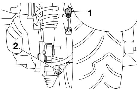
- Final transmission oil filler cap
- Final transmission oil drain bolt
- Install the final transmission oil drain bolt, and then tighten it to the specified torque.
Tightening torque:
Final transmission oil drain bolt: 20 Nm (2.0 m·kgf, 14.5 ft·lbf)
- Refill with the specified amount of the recommended final transmission oil, and then install and tighten the oil filler cap. WARNING! Make sure that no foreign material enters the final transmission case. Make sure that no oil gets on the tire or wheel.[EWA11311]
Recommended final transmission oil:
See page 8-1.
Oil quantity:
0.25 L (0.26 US qt, 0.22 Imp qt)
- Check the final transmission case for oil leakage. If oil is leaking, check for the cause.
EAU20070
Coolant
The coolant level should be checked before each ride. In addition, the coolant must be changed at the intervals specified in the periodic maintenance and lubrication chart.
EAU34193
To check the coolant level
- Place the vehicle on a level surface and hold it in an upright position.
TIP
- The coolant level must be checked on a cold engine since the level varies with engine temperature.
-
Make sure that the vehicle is positioned straight up when checking the coolant level. A slight tilt to the side can result in a false reading.
-
Pull up the right floorboard mat as shown.
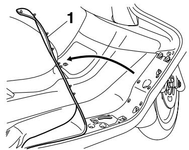
- Right floorboard mat
- Remove the coolant reservoir cover by removing the screw.
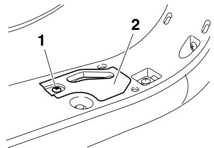
- Screw
- Coolant reservoir cover
- Check the coolant level in the coolant reservoir.
TIP
The coolant should be between the minimum and maximum level marks.
- If the coolant is at or below the minimum level mark, open the coolant reservoir cap, add coolant to the maximum level mark, and then close the coolant reservoir cap. WARNING! Remove only the coolant reservoir cap. Never attempt to remove the radiator cap when the engine is hot.[EWA15161] NOTICE: If coolant is not available, use distilled water or soft tap water instead. Do not use hard water or salt water since it is harmful to the engine. If water has been used instead of coolant, replace it with coolant as soon as possible, otherwise the cooling system will not be protected against frost and corrosion. If water has been added to the coolant, have a Yamaha dealer check the antifreeze content of the coolant as soon as possible, otherwise the effectiveness of the coolant will
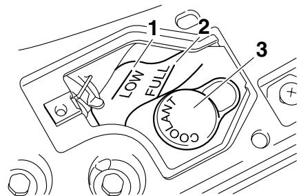
be reduced.[ECA10472]
- Minimum level mark
- Maximum level mark
- Coolant reservoir cap
Coolant reservoir capacity (up to the maximum level mark): 0.32 L (0.34 US qt, 0.28 Imp. qt)
- Install the coolant reservoir cover by installing the screw.
- Place the right floorboard mat in the original position.
EAU34206
Air filter elements and check hoses and V-belt case air filter element
The air filter elements and the V-belt case air filter element should be serviced at the intervals specified in the periodic maintenance and lubrication chart. Service all air filter elements more frequently if you are riding in unusually wet or dusty areas.
Replacing the air filter elements
- Place the scooter on the centerstand.
TIP
Continue as follows for each air filter element.
- Remove the air filter case cover by removing the rubber caps and screws.
Left
- Screw
- Air filter case cover
- Rubber cap
Right
- Screw
- Air filter case cover
-
Rubber cap
-
Pull the air filter element out.
Left
- Air filter element
Right

-
Air filter element
-
Insert a new air filter element into the air filter case.
- Install the air filter case cover by in
stalling the screws. NOTICE: Make sure that each filter element is properly seated in its case. Always replace both air filter elements at the same time, otherwise poor engine performance or damage to the engine may result. The engine should never be operated without the filter elements installed, otherwise the piston(s) and/or cylinder(s) may become excessively worn.[ECA12923]
- Install the rubber cap.
To clean the air filter check hoses
- Check the hose at the bottom of both air filter cases for accumulated dirt or water.
Left
1. Air filter check hose
Right

1. Air filter check hose
- If dirt or water is visible, remove the hose, clean it, and then install it.
Cleaning the V-belt case air filter element
- Remove cowling E. (See page 6-7.)
- Remove panel A. (See page 6-7.)
- Remove the left air filter case cover.
- Remove the V-belt air filter case cover by removing the screws.
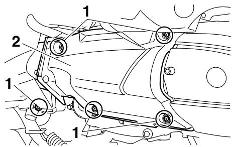
- Screw
- V-belt air filter case cover
- Remove the V-belt case air filter element by removing the screws.
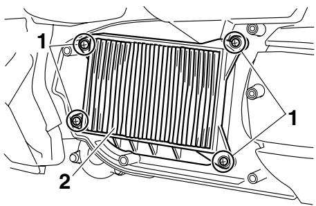
- Screw
- V-belt case air filter element
- Lightly tap the V-belt case air filter element to remove most of the dust and dirt, and then blow out the dirt with compressed air as shown.
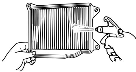
- Check the V-belt case air filter element for damage and replace it if
necessary.
- Install the V-belt case air filter element by installing the screws. NOTICE: Make sure that the V-belt filter element is properly seated in its case.[ECA12941]
- Install the V-belt air filter case cover by installing the screws.
- Install the left air filter case cover.
- Install the panel.
- Install the cowling.
EAU21382
Checking the throttle cable free play
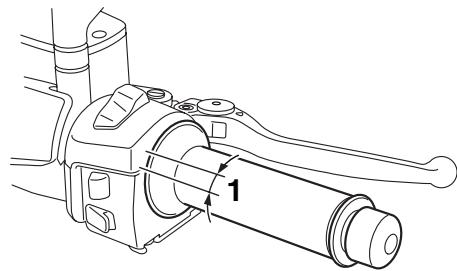
1. Throttle cable free play
The throttle cable free play should measure 3.0-5.0 mm (0.12-0.20 in) at the throttle grip. Periodically check the throttle cable free play and, if necessary, have a Yamaha dealer adjust it.
EAU21401
Valve clearance
The valve clearance changes with use, resulting in improper air-fuel mixture and/or engine noise. To prevent this from occurring, the valve clearance must be adjusted by a Yamaha dealer at the intervals specified in the periodic maintenance and lubrication chart.
EAU21873
Tires
To maximize the performance, durability, and safe operation of your vehicle, note the following points regarding the specified tires.
Tire air pressure
The tire air pressure should be checked and, if necessary, adjusted before each ride.
EWA10501
WARNING
Operation of this vehicle with improper tire pressure may cause severe injury or death from loss of control.
- The tire air pressure must be checked and adjusted on cold tires (i.e., when the temperature of the tires equals the ambient temperature).
- The tire air pressure must be adjusted in accordance with the riding speed and with the total weight of rider, passenger, cargo, and accessories approved for this model.
Tire air pressure (measured on cold tires):
0-90 kg (0-198 lb):
Front:
200 kPa (2.00 kgf/cm², 29 psi)
Rear:
250 kPa (2.50 kgf/cm², 36 psi)
90-185 kg (198-408 lb):
Front:
200 kPa (2.00 kgf/cm², 29 psi)
Rear:
250 kPa (2.50 kgf/cm², 36 psi)
Maximum load*:
185 kg (408 lb)
- Total weight of rider, passenger, cargo and accessories
EWA10511
WARNING
Never overload your vehicle. Operation of an overloaded vehicle could cause an accident.
Tire inspection
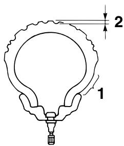
- Tire sidewall
- Tire tread depth
The tires must be checked before each ride. If the center tread depth reaches the specified limit, if the tire has a nail or glass fragments in it, or if the sidewall is cracked, have a Yamaha dealer replace the tire immediately.
Minimum tire tread depth (front and rear):
1.6 mm (0.06 in)
TIP
The tire tread depth limits may differ from country to country. Always comply with the local regulations.
Tire information
This model is equipped with tubeless tires.
After extensive tests, only the tires listed below have been approved for this model by Yamaha Motor Co., Ltd.
Front tire:
Size:
120/80-14M/C 58S
Manufacturer/model:
IRC/MB67
DUNLOP/D305FL
Rear tire:
Size:
150/70-13M/C 64S
Manufacturer/model:
IRC/MB67
DUNLOP/D305L
EWA10470
WARNING
- Have a Yamaha dealer replace excessively worn tires. Besides being illegal, operating the vehicle with excessively worn tires decreases riding stability and can lead to loss of control.
- The replacement of all wheel and brake related parts, including the tires, should be left to a
Yamaha dealer, who has the necessary professional knowledge and experience.
EAU21992
Cast wheels
To maximize the performance, durability, and safe operation of your vehicle, note the following points regarding the specified wheels.
- The wheel rims should be checked for cracks, bends, warpage or damage before each ride. If any damage is found, have a Yamaha dealer replace the wheel. Do not attempt even the smallest repair to the wheel. A deformed or cracked wheel must be replaced.
- The wheel should be balanced whenever either the tire or wheel has been changed or replaced. An unbalanced wheel can result in poor performance, adverse handling characteristics, and a shortened tire life.
- Ride at moderate speeds after changing a tire since the tire surface must first be "broken in" for it to develop its optimal characteristics.
- After repairing or replacing the rear tire, tighten the valve stem nut and locknut to the specified torques.
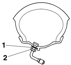
Front and rear brake lever free play
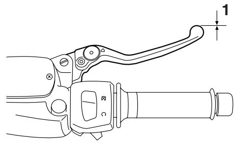
Front
1. Brake lever free play
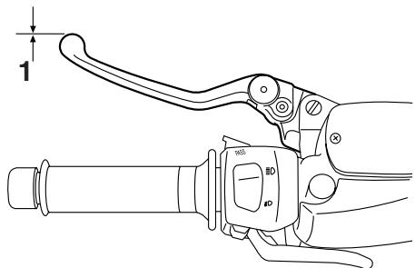
Rear
1. Brake lever free play
There should be no free play at the
PERIODIC MAINTENANCE AND ADJUSTMENT
brake lever ends. If there is free play, have a Yamaha dealer inspect the brake system.
EWA14211
WARNING
A soft or spongy feeling in the brake lever can indicate the presence of air in the hydraulic system. If there is air in the hydraulic system, have a Yamaha dealer bleed the system before operating the vehicle. Air in the hydraulic system will diminish the braking performance, which may result in loss of control and an accident.
EAU33473
Adjusting the rear brake lock lever cable
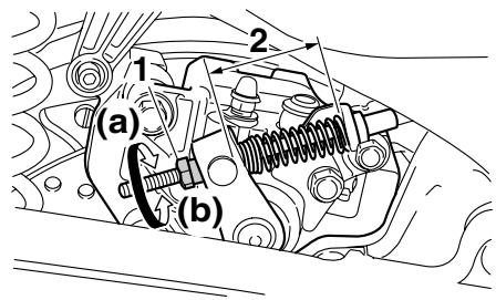
- Adjusting nut
- Rear brake lock lever cable length
Rear brake lock lever cable adjustment may be required if the rear brake lock lever does not hold properly. When the rear brake lock lever is not in use, the rear brake lock lever cable length should measure 45mm to 47mm (1.77 in to 1.85 in) at the rear brake caliper. Periodically check the rear brake lock lever cable length and, if necessary, adjust it as follows.
To increase the rear brake lock lever cable length, turn the adjusting nut at the rear brake caliper in direction (a).
To decrease the rear brake lock lever cable length, turn the adjusting nut in direction (b).
WARNING
EWA10650
If proper adjustment cannot be obtained as described, have a Yamaha dealer make this adjustment.
EAU22390
Checking the front and rear brake pads
The front and rear brake pads must be checked for wear at the intervals specified in the periodic maintenance and lubrication chart.
EAU22430
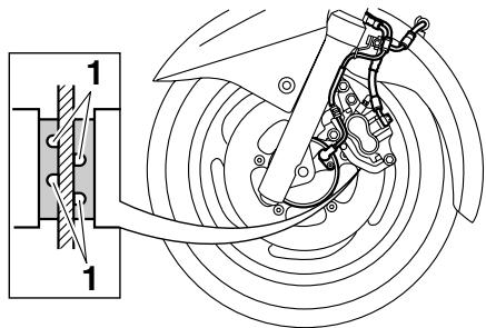
Front brake pads
1. Wear indicator groove
Each front brake pad is provided with wear indicator grooves, which allow you to check the brake pad wear without having to disassemble the brake. To check the brake pad wear, check the wear indicator grooves. If a brake pad has worn to the point that the wear
indicator grooves have almost disappeared, have a Yamaha dealer replace the brake pads as a set.
EAU34210
Rear brake pads
Have a Yamaha dealer check each rear brake pad for damage and measure the lining thickness and if necessary, replace them as a set.
EAU40260
Checking the brake fluid level
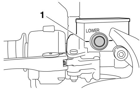
Front brake
1. Minimum level mark
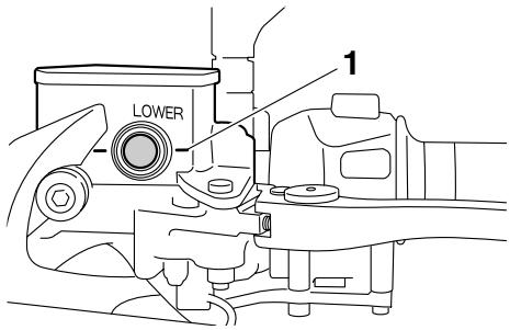
Rear brake
1. Minimum level mark
Insufficient brake fluid may allow air to enter the brake system, possibly caus
ing it to become ineffective.
Before riding, check that the brake fluid is above the minimum level mark and replenish if necessary. A low brake fluid level may indicate worn brake pads and/or brake system leakage. If the brake fluid level is low, be sure to check the brake pads for wear and the brake system for leakage.
Observe these precautions:
- When checking the fluid level, make sure that the top of the brake fluid reservoir is level.
- Use only the recommended quality brake fluid, otherwise the rubber seals may deteriorate, causing leakage and poor braking performance.
Recommended brake fluid: DOT 4
- Refill with the same type of brake fluid. Mixing fluids may result in a harmful chemical reaction and lead to poor braking performance.
- Be careful that water or dust does not enter the brake fluid reservoir when refilling. Water will signifi
cantly lower the boiling point of the fluid and may result in vapor lock, and dirt may clog the ABS hydraulic unit valves.
- Brake fluid may deteriorate painted surfaces or plastic parts. Always clean up spilled fluid immediately.
- As the brake pads wear, it is normal for the brake fluid level to gradually go down. However, if the brake fluid level goes down suddenly, have a Yamaha dealer check the cause.
EAU22731
Changing the brake fluid
Have a Yamaha dealer change the brake fluid at the intervals specified in the TIP after the periodic maintenance and lubrication chart. In addition, have the oil seals of the master cylinders and calipers as well as the brake hoses replaced at the intervals listed below or whenever they are damaged or leaking.
- Oil seals: Replace every two years.
- Brake hoses: Replace every four years.
EAU23101
Checking and lubricating the cables
The operation of all control cables and the condition of the cables should be checked before each ride, and the cables and cable ends should be lubricated if necessary. If a cable is damaged or does not move smoothly, have a Yamaha dealer check or replace it. WARNING! Damage to the outer sheath may interfere with proper cable operation and will cause the inner cable to rust. Replace a damaged cable as soon as possible to prevent unsafe conditions.[EWA10721]
Recommended lubricant:
Engine oil
EAU23111
Checking and lubricating the throttle grip and cable
The operation of the throttle grip should be checked before each ride. In addition, the cable should be lubricated at the intervals specified in the periodic maintenance chart.
EAU23172
Lubricating the front and rear brake levers
Front brake lever
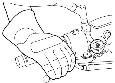
Rear brake lever
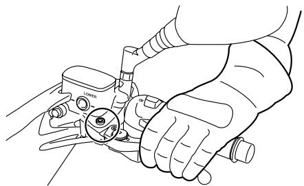
The pivoting points of the front and rear brake levers must be lubricated at the intervals specified in the periodic maintenance and lubrication chart.
Recommended lubricant: Silicone grease
EAU23213
Checking and lubricating the centerstand and sidestand
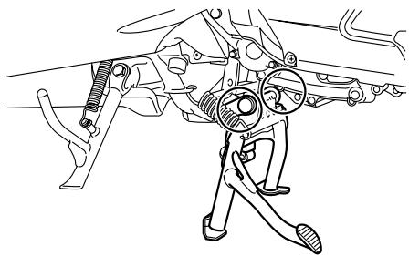

WARNING
EWA10741
If the centerstand or sidestand does not move up and down smoothly, have a Yamaha dealer check or repair it. Otherwise, the centerstand or sidestand could contact the ground and distract the operator, resulting in a possible loss of control.
Recommended lubricant: Lithium-soap-based grease

The operation of the centerstand and sidestand should be checked before each ride, and the pivots and metal-to-metal contact surfaces should be lubricated if necessary.
EAU23272
Checking the front fork
The condition and operation of the front fork must be checked as follows at the intervals specified in the periodic maintenance and lubrication chart.
To check the condition
Check the inner tubes for scratches, damage and excessive oil leakage.
To check the operation
- Place the vehicle on a level surface and hold it in an upright position. WARNING! To avoid injury, securely support the vehicle so there is no danger of it falling over.[EWA10751]
- While applying the front brake, push down hard on the handlebars several times to check if the front fork compresses and rebounds smoothly.
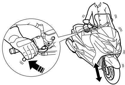
ECA10590
NOTICE
If any damage is found or the front fork does not operate smoothly, have a Yamaha dealer check or repair it.
EAU45511
Checking the steering
Worn or loose steering bearings may cause danger. Therefore, the operation of the steering must be checked as follows at the intervals specified in the periodic maintenance and lubrication chart.
- Place the vehicle on the centerstand. WARNING! To avoid injury, securely support the vehicle so there is no danger of it falling over.[EWA10751]
- Hold the lower ends of the front fork legs and try to move them forward and backward. If any free play can be felt, have a Yamaha dealer check or repair the steering.
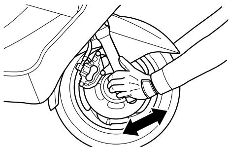
EAU23290
Checking the wheel bearings
The front and rear wheel bearings must be checked at the intervals specified in the periodic maintenance and lubrication chart. If there is play in the wheel hub or if the wheel does not turn smoothly, have a Yamaha dealer check the wheel bearings.
EAU34224
Battery
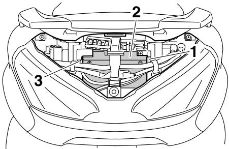
- Negative battery lead (black)
- Battery
- Positive battery lead (red)
The battery is located behind cowling A. (See page 6-7.)
This model is equipped with a VRLA (Valve Regulated Lead Acid) battery. There is no need to check the electrolyte or to add distilled water. However, the battery lead connections need to be checked and, if necessary, tightened.
EWA10760
WARNING
- Electrolyte is poisonous and dangerous since it contains sulfuric acid, which causes severe
burns. Avoid any contact with skin, eyes or clothing and always shield your eyes when working near batteries. In case of contact, administer the following FIRST AID.
- EXTERNAL: Flush with plenty of water.
- INTERNAL: Drink large quantities of water or milk and immediately call a physician.
-
EYES: Flush with water for 15 minutes and seek prompt medical attention.
-
Batteries produce explosive hydrogen gas. Therefore, keep sparks, flames, cigarettes, etc., away from the battery and provide sufficient ventilation when charging it in an enclosed space.
- KEEP THIS AND ALL BATTERIES OUT OF THE REACH OF CHILDREN.
To charge the battery
Have a Yamaha dealer charge the battery as soon as possible if it seems to
have discharged. Keep in mind that the battery tends to discharge more quickly if the vehicle is equipped with optional electrical accessories.
ECA16520
NOTICE
To charge a VRLA (Valve Regulated Lead Acid) battery, a special (constant-voltage) battery charger is required. Using a conventional battery charger will damage the battery. If you do not have access to a constant-voltage battery charger, have a Yamaha dealer charge your battery.
To store the battery
- If the vehicle will not be used for more than one month, remove the battery, fully charge it, and then place it in a cool, dry place. NOTICE: When removing the battery, be sure the key is turned to "OFF", then disconnect the negative lead before disconnecting the positive lead.[ECA16302]
- If the battery will be stored for more than two months, check it at least
once a month and fully charge it if necessary.
- Fully charge the battery before installation.
- After installation, make sure that the battery leads are properly connected to the battery terminals.
ECA16530
NOTICE
Always keep the battery charged. Storing a discharged battery can cause permanent battery damage.
EAU23615
Replacing the fuses
The main fuse and the fuse box, which contains the fuses for the individual circuits, are located behind cowling A. (See page 6-7.)
If a fuse is blown, replace it as follows.
- Turn the key to "OFF" and turn off the electrical circuit in question.
- Remove the blown fuse, and then install a new fuse of the specified amperage. WARNING! Do not use a fuse of a higher amperage rating than recommended to avoid causing extensive damage to the electrical system and possibly a fire.[EWA15131]
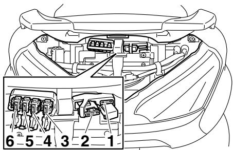
- Spare main fuse
- Main fuse
- Hazard fuse
- ABS control unit fuse
- ABS solenoid fuse
- ABS motor fuse
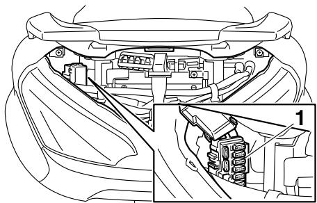
- Fuse box
- Ignition fuse
- Signaling system fuse
- Headlight fuse
- Radiator fan fuse
- Backup fuse (for odometer and clock)
- Fuel injection system fuse
- Spare fuse
Specified fuses:
Main fuse:
40.0 A
Ignition fuse:
10.0 A
Signaling system fuse:
10.0 A
Headlight fuse:
20.0 A
Hazard fuse:
10.0 A
Radiator fan fuse:
10.0 A
Fuel injection system fuse:
10.0 A
ABS control unit fuse:
10.0 A
ABS motor fuse:
30.0 A
ABS solenoid fuse:
20.0 A
Backup fuse:
10.0 A
- Turn the key to "ON" and turn on the electrical circuit in question to check if the device operates.
- If the fuse immediately blows again, have a Yamaha dealer check the electrical system.
EAU34240
Replacing a headlight bulb
This model is equipped with quartz bulb headlights. If a headlight bulb burns out, have a Yamaha dealer replace it and, if necessary, adjust the headlight beam.
EAU24181
Tail/brake light
This model is equipped with an LED-type tail/brake light. If the tail/brake light does not come on, have a Yamaha dealer check it.
EAU39880
Front turn signal light
If a front turn signal light does not come on, have a Yamaha dealer check its electrical circuit or replace the bulb.
EAU34263
Replacing a rear turn signal light bulb
- Place the scooter on the centerstand.
- Remove cowling C for replacing the left turn signal light bulb or cowling D for replacing the right turn signal light bulb. (See page 6-7.)
- Remove the socket (together with the turn signal light bulb) by turning it counterclockwise.
-
Turn signal light bulb socket
-
Remove the burnt-out bulb by pushing it in and turning it counterclockwise.
- Insert a new bulb into the socket,
push it in, and then turn it clockwise until it stops.

- Turn signal light bulb
- Turn signal light bulb socket
- Install the socket (together with the bulb) by turning it clockwise.
- Install the cowling removed.
EAU47900
Replacing the license plate light bulb
- Place the scooter on the centerstand.
- Remove cowling B. (See page 6-7.)
- Remove the license plate light cover and license plate light lens by removing the screws.
- License plate light lens
- License plate light cover
- Screw
- Remove the burnt-out bulb by pulling it out.
- License plate light bulb
- Insert a new bulb into the socket.
- Install the license plate light lens and license plate light cover by installing the screws.
- Install the cowling.
EAU39020
Auxiliary light bulb
If the auxiliary light does not come on, have a Yamaha dealer check the electrical circuit or replace the bulb.
EAU25881
Troubleshooting
Although Yamaha scooters receive a thorough inspection before shipment from the factory, trouble may occur during operation. Any problem in the fuel, compression, or ignition systems, for example, can cause poor starting and loss of power.
The following troubleshooting charts represent quick and easy procedures for checking these vital systems yourself. However, should your scooter require any repair, take it to a Yamaha dealer, whose skilled technicians have the necessary tools, experience, and know-how to service the scooter properly.
Use only genuine Yamaha replacement parts. Imitation parts may look like Yamaha parts, but they are often inferior, have a shorter service life and can lead to expensive repair bills.
EWA15141

WARNING
When checking the fuel system, do not smoke, and make sure there are no open flames or sparks in the area, including pilot lights from water
PERIODIC MAINTENANCE AND ADJUSTMENT
heaters or furnaces. Gasoline or gasoline vapors can ignite or explode, causing severe injury or property damage.
EAU42701
Troubleshooting charts
Starting problems or poor engine performance
1. Fuel
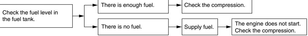
2. Compression
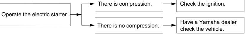
3. Ignition
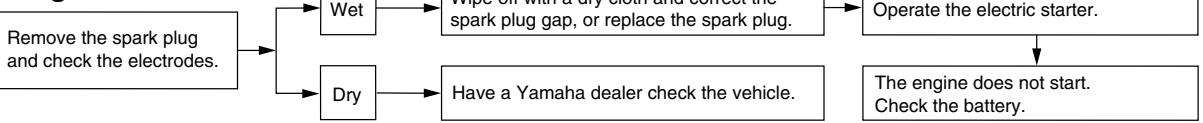
4. Battery

Engine overheating

WARNING
EWAT1040
- Do not remove the radiator cap when the engine and radiator are hot. Scalding hot fluid and steam may be blown out under pressure, which could cause serious injury. Be sure to wait until the engine has cooled.
- Place a thick rag, like a towel, over the radiator cap, and then slowly rotate the cap counterclockwise to the detent to allow any residual pressure to escape. When the hissing sound has stopped, press down on the cap while turning it counterclockwise, and then remove the cap.
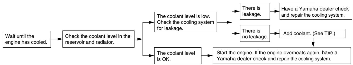
TIP
If coolant is not available, tap water can be temporarily used instead, provided that it is changed to the recommended coolant as soon as possible.
EAU37833
Matte color caution
ECA15192
NOTICE
Some models are equipped with matte colored finished parts. Be sure to consult a Yamaha dealer for advice on what products to use before cleaning the vehicle. Using a brush, harsh chemical products or cleaning compounds when cleaning these parts will scratch or damage their surface. Wax also should not be applied to any matte colored finished parts.
Care
While the open design of a scooter reveals the attractiveness of the technology, it also makes it more vulnerable. Rust and corrosion can develop even if high-quality components are used. A rusty exhaust pipe may go unnoticed on a car, however, it detracts from the overall appearance of a scooter. Frequent and proper care does not only comply with the terms of the warranty, but it will also keep your scooter looking good, extend its life and optimize its performance.
Before cleaning
- Cover the muffler outlet with a plastic bag after the engine has cooled down.
- Make sure that all caps and covers as well as all electrical couplers and connectors, including the spark plug cap, are tightly installed.
- Remove extremely stubborn dirt, like oil burnt onto the crankcase, with a degreasing agent and a brush, but never apply such prod
EAU26093
ucts onto seals, gaskets and wheel axles. Always rinse the dirt and degreaser off with water.
Cleaning
ECA10782
NOTICE
- Avoid using strong acidic wheel cleaners, especially on spiked wheels. If such products are used on hard-to-remove dirt, do not leave the cleaner on the affected area any longer than instructed. Also, thoroughly rinse the area off with water, immediately dry it, and then apply a corrosion protection spray.
- Improper cleaning can damage plastic parts (such as cowlings, panels, windshields, headlight lenses, meter lenses, etc.) and the mufflers. Use only a soft, clean cloth or sponge with water to clean plastic. However, if the plastic parts cannot be thoroughly cleaned with water, diluted mild detergent with water may be used. Be sure to rinse off any detergent residue using
plenty of water, as it is harmful to plastic parts.
- Do not use any harsh chemical products on plastic parts. Be sure to avoid using cloths or sponges which have been in contact with strong or abrasive cleaning products, solvent or thinner, fuel (gasoline), rust removers or inhibitors, brake fluid, antifreeze or electrolyte.
- Do not use high-pressure washers or steam-jet cleaners since they cause water seepage and deterioration in the following areas: seals (of wheel and swing-arm bearings, fork and brakes), electric components (couplers, connectors, instruments, switches and lights), breather hoses and vents.
- For scooters equipped with a windshield: Do not use strong cleaners or hard sponges as they will cause dulling or scratching. Some cleaning compounds for plastic may leave scratches on the windshield.
Test the product on a small hidden part of the windshield to make sure that it does not leave any marks. If the windshield is scratched, use a quality plastic polishing compound after washing.
After normal use
Remove dirt with warm water, a mild detergent, and a soft, clean sponge, and then rinse thoroughly with clean water. Use a toothbrush or bottlebrush for hard-to-reach areas. Stubborn dirt and insects will come off more easily if the area is covered with a wet cloth for a few minutes before cleaning.
After riding in the rain, near the sea or on salt-sprayed roads
Since sea salt or salt sprayed on the roads during winter are extremely corrosive in combination with water, carry out the following steps after each ride in the rain, near the sea or on salt-sprayed roads.
TIP
Salt sprayed on roads in the winter may
remain well into spring.
- Clean the scooter with cold water and a mild detergent after the engine has cooled down. NOTICE: Do not use warm water since it increases the corrosive action of the salt.[ECA10791]
- Apply a corrosion protection spray on all metal, including chrome- and nickel-plated, surfaces to prevent corrosion.
After cleaning
- Dry the scooter with a chamois or an absorbing cloth.
- Use a chrome polish to shine chrome, aluminum and stainless-steel parts, including the exhaust system. (Even the thermally induced discoloring of stainless-steel exhaust systems can be removed through polishing.)
- To prevent corrosion, it is recommended to apply a corrosion protection spray on all metal, including chrome- and nickel-plated, surfaces.
- Use spray oil as a universal clean
er to remove any remaining dirt.
- Touch up minor paint damage caused by stones, etc.
- Wax all painted surfaces.
- Let the scooter dry completely before storing or covering it.
EWA10941
WARNING
Contaminants on the brakes or tires can cause loss of control.
- Make sure that there is no oil or wax on the brakes or tires. If necessary, clean the brake discs and brake linings with a regular brake disc cleaner or acetone, and wash the tires with warm water and a mild detergent.
- Before operating the scooter test its braking performance and cornering behavior.
ECA10800
NOTICE
- Apply spray oil and wax sparingly and make sure to wipe off any excess.
- Never apply oil or wax to any rubber and plastic parts, but
treat them with a suitable care product.
- Avoid using abrasive polishing compounds as they will wear away the paint.
TIP
- Consult a Yamaha dealer for advice on what products to use.
- Washing, rainy weather or humid climates can cause the headlight lens to fog. Turning the headlight on for a short period of time will help remove the moisture from the lens.
EAU36561
Storage
Short-term
Always store your scooter in a cool, dry place and, if necessary, protect it against dust with a porous cover.
ECA10820
NOTICE
- Storing the scooter in a poorly ventilated room or covering it with a tarp, while it is still wet, will allow water and humidity to seep in and cause rust.
- To prevent corrosion, avoid damp cellars, stables (because of the presence of ammonia) and areas where strong chemicals are stored.
Long-term
Before storing your scooter for several months:
- Follow all the instructions in the "Care" section of this chapter.
- Fill up the fuel tank and add fuel stabilizer (if available) to prevent the fuel tank from rusting and the
fuel from deteriorating.
- Perform the following steps to protect the cylinder, piston rings, etc. from corrosion.
a. Remove the spark plug cap and spark plug.
b. Pour a teaspoonful of engine oil into the spark plug bore.
c. Install the spark plug cap onto the spark plug, and then place the spark plug on the cylinder head so that the electrodes are grounded. (This will limit sparking during the next step.)
d. Turn the engine over several times with the starter. (This will coat the cylinder wall with oil.)
e. Remove the spark plug cap from the spark plug, and then install the spark plug and the spark plug cap. WARNING! To prevent damage or injury from sparking, make sure to ground the spark plug electrodes while turning the engine over.[EWA10951]
4. Lubricate all control cables and the pivoting points of all levers and
pedals as well as of the sidestand/ centerstand.
- Check and, if necessary, correct the tire air pressure, and then lift the scooter so that both of its wheels are off the ground. Alternatively, turn the wheels a little every month in order to prevent the tires from becoming degraded in one spot.
- Cover the muffler outlet with a plastic bag to prevent moisture from entering it.
- Remove the battery and fully charge it. Store it in a cool, dry place and charge it once a month. Do not store the battery in an excessively cold or warm place [less than 0^ (30°F) or more than 30^ (90°F)]. For more information on storing the battery, see page 6-30.
TIP
Make any necessary repairs before storing the scooter.
Dimensions:
Overall length:
2230 mm (87.8 in)
Overall width:
780 mm (30.7 in)
Overall height:
1380 mm (54.3 in)
Seat height:
760 mm (29.9 in)
Wheelbase:
1565 mm (61.6 in)
Ground clearance:
120 mm (4.72 in)
Minimum turning radius:
2600 mm (102.4 in)
Weight:
With oil and fuel:
223.0 kg (492 lb)
Engine:
Engine type:
Liquid cooled 4-stroke, DOHC
Cylinder arrangement:
Forward-inclined single cylinder
Displacement:
395 cm³
Bore × stroke:
83.0 × 73.0 ~mm (3.27 × 2.87 in)
Compression ratio:
10.60:1
Starting system:
Electric starter
Lubrication system:
Wet sump
Engine oil:
Recommended brand:
YAMALUBE
Type:
SAE 10W-30, SAE 10W-40, SAE 15W-40, SAE 20W-40 or SAE 20W-50
Recommended engine oil grade:
API service SG type or higher, JASO standard MA
Engine oil quantity:
Without oil filter element replacement:
1.50 L (1.59 US qt, 1.32 Imp qt)
With oil filter element replacement:
1.70 L (1.80 US qt, 1.50 Imp qt)
Final transmission oil:
Type:
YAMALUBE 10W-40 or SAE 10W-30 type
SE motor oil
Quantity:
0.25 L (0.26 US qt, 0.22 Imp qt)
Cooling system:
Coolant reservoir capacity (up to the maxi
mum level mark):
0.32 L (0.34 US qt, 0.28 Imp qt)
Radiator capacity (including all routes):
1.57 L (1.66 US qt, 1.38 Imp qt)
Air filter:
Air filter element:
Oil-coated paper element
Fuel:
Recommended fuel:
Regular unleaded gasoline only
Fuel tank capacity:
14.0 L (3.70 US gal, 3.08 Imp.gal)
Fuel injection:
Throttle body:
ID mark:
5RUG 20
Spark plug (s):
Manufacturer/model:
NGK/CR7E
Spark plug gap:
0.7-0.8 mm (0.028-0.031 in)
Clutch:
Clutch type:
Dry, centrifugal automatic
Transmission:
Primary reduction system:
Helical gear
Primary reduction ratio:
31/14 (2.214)
Secondary reduction system:
Helical gear
Secondary reduction ratio: 42/14 (3.000)
Transmission type: V-belt automatic
Operation: Centrifugal automatic type
Chassis:
Frame type: Aluminum die-cast and steel tube backbone
Caster angle: 27.00°
Trail: 100.0 mm (3.94 in)
Front tire:
Type: Tubeless
Size: 120/80-14M/C 58S
Manufacturer/model: IRC/MB67
Manufacturer/model: DUNLOP/D305FL
Rear tire:
Type: Tubeless
Size: 150/70-13M/C 64S
Manufacturer/model: IRC/MB67
Manufacturer/model: DUNLOP/D305L
Loading:
Maximum load: 185 kg (408 lb)
- (Total weight of rider, passenger, cargo and accessories)
Tire air pressure (measured on cold tires):
Loading condition: 0-90 kg (0-198 lb)
Front:
200 kPa (2.00 kgf/cm², 29 psi)
Rear:
250 kPa (2.50 kgf/cm², 36 psi)
Loading condition: 90-185 kg (198-408 lb)
Front:
200 kPa (2.00 kgf/cm², 29 psi)
Rear:
250 kPa (2.50 kgf/cm², 36 psi)
Front wheel:
Wheel type:
Cast wheel
Rim size:
14M/C x MT3.00
Rear wheel:
Wheel type: Cast whe
Rim size: 13M/C x MT4.00
Front brake:
Type:
Dual disc brake
Operation:
Right hand operation
Recommended fluid: DOT 4
Rear brake:
Type: Single disc brake
Operation: Left hand operation
Recommended fluid: DOT 4
Front suspension:
Type: Telescopic fork
Spring/shock absorber type: Coil spring/oil damper
Wheel travel: 120.0 mm (4.72 in)
Rear suspension:
Type: Unit swing
Spring/shock absorber type: Coil spring/oil damper
Wheel travel: 104.0 mm (4.09 in)
Electrical system:
Ignition system: TCI (digital)
Charging system: AC magneto
Battery:
Model: GT9B-4
Voltage, capacity: 12 V, 8.0 Ah
Headlight:
Bulb type:
Halogen bulb
Bulb voltage, wattage × quantity:
Headlight:
12V,60W/55W×1
Headlight:
12V,55W×1
Tail/brake light:
LED
Front turn signal light:
12V,21.0W×2
Rear turn signal light:
12V, 21.0 W × 2
Auxiliary light:
12V,5.0W×2
License plate light:
12V,5.0W×1
Meter lighting:
12V,2.0W×3
High beam indicator light:
12V, 1.4 W×1
Turn signal indicator light:
12V,1.4W×2
Engine trouble warning light:
12V, 1.4 W×1
ABS warning light:
12V, 1.4 W×1
Immobilizer system indicator light:
LED
Fuses:
Main fuse:
40.0 A
Headlight fuse:
20.0 A
Signaling system fuse:
10.0 A
Ignition fuse:
10.0 A
Radiator fan fuse:
10.0 A
Hazard fuse:
10.0 A
Fuel injection system fuse:
10.0 A
ABS control unit fuse:
10.0 A
ABS motor fuse:
30.0 A
ABS solenoid fuse:
20.0 A
Backup fuse:
10.0 A
EAU26352
Identification numbers
Record the key identification number, vehicle identification number and model label information in the spaces provided below for assistance when ordering spare parts from a Yamaha dealer or for reference in case the vehicle is stolen.
KEY IDENTIFICATION NUMBER:
VEHICLE IDENTIFICATION NUMBER:
MODEL LABEL INFORMATION:
O
EAU26381
Key identification number
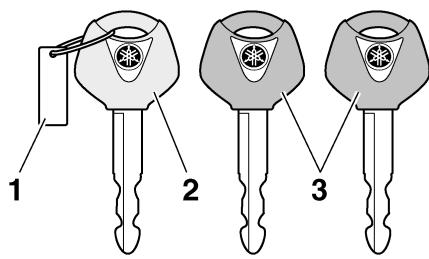
- Key identification number
- Code re-registering key (red bow)
- Standard keys (black bow)
The key identification number is stamped into the key tag. Record this number in the space provided and use it for reference when ordering a new key.
EAU26410
Vehicle identification number
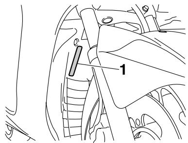
- Vehicle identification number
The vehicle identification number is stamped into the frame.
TIP
The vehicle identification number is used to identify your vehicle and may be used to register it with the licensing authority in your area.
EAU26500
Model label
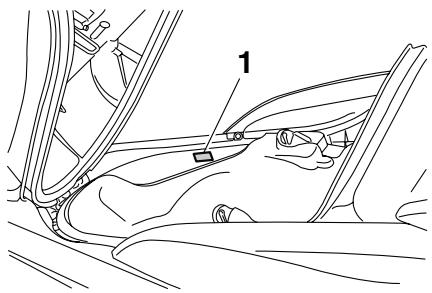
1. Model label
The model label is affixed to the inside of the rear storage compartment. (See page 3-19.) Record the information on this label in the space provided. This information will be needed when ordering spare parts from a Yamaha dealer.
A
ABS. 3-13
ABS warning light. 3-4
Acceleration and deceleration. 5-2
Air filter elements and check hoses and V-belt case air filter element 6-18
Anti-theft alarm (optional) 3-9
Auxiliary light bulb 6-35
B
Battery. 6-30
Brake fluid, changing 6-26
Brake fluid level, checking 6-25
Brake lever, front. 3-11
Brake lever, rear 3-12
Brake levers, lubricating. 6-27
Braking. 5-3
C
Cables, checking and lubricating 6-27
Care 7-1
Catalytic converters 3-16
Centerstand and sidestand, checking and lubricating 6-28
Coolant 6-16
Cowlings and panels, removing and installing. 6-7
D
Dimmer switch 3-10
E
Engine break-in. 5-4
Engine oil and oil filter element 6-12
Engine stop switch 3-10
Engine trouble warning light 3-3
F
Final transmission oil 6-15
Front and rear brake lever free play.....6-23
Front and rear brake pads, checking.....6-25
Front fork, checking 6-29
Front turn signal light 6-33
Fuel. 3-15
Fuel consumption, tips for reducing. 5-3
Fuel tank cap. 3-14
Fuses, replacing 6-31
H
Handlebar switches 3-10
Hazard switch 3-11
Headlight bulb, replacing. 6-33
High beam indicator light. 3-3
Horn switch. 3-10
1
Identification numbers 9-1
Ignition circuit cut-off system 3-22
Immobilizer system 3-1
Immobilizer system indicator light. 3-4
Indicator and warning lights. 3-3
K
Key identification number 9-1
L
License plate light bulb, replacing .6-34
M
Main switch/steering lock. 3-2
Maintenance and lubrication, periodic. 6-4
Maintenance, emission control system.....6-3
Matte color, caution 7-1
Model label 9-2
Multi-function display 3-5
P
Parking 5-4
Part locations. 2-1
Pass switch 3-10
R
Rear brake lock lever 3-12
Rear brake lock lever cable, adjusting .... 6-24
Rider seat, adjusting 3-18
s
Safe-riding points 1-5
Safety information 1-1
Seats 3-17
Shock absorber assemblies, adjusting.... 3-21
Sidestand 3-21
Spark plug, checking. 6-10
Specifications 8-1
Speedometer 3-5
Starting off 5-2
Starting the engine 5-1
Start switch. 3-10
Steering, checking. 6-29
Storage 7-3
Storage compartments. 3-19
T
Tachometer 3-5
Tail/brake light 6-33
Throttle cable free play, checking 6-20
Throttle grip and cable, checking and lubricating. 6-27
Tires 6-21
Tool kit. 6-1
Troubleshooting 6-35
Troubleshooting charts. 6-37
Turn signal indicator lights 3-3
Turn signal light bulb (rear), replacing.... 6-34
Turn signal switch 3-10
V
Valve clearance 6-21
Vehicle identification number. 9-1
W
Wheel bearings, checking 6-30
Wheels. 6-23
- Read this manual carefully before operating this vehicle. This manual should stay with this vehicle if it is sold.
- YAMAHA
- DECLARATION of CONFORMITY
- We
- INSTRUMENT AND CONTROL
- FOR YOUR SAFETY -
- PERIODIC MAINTENANCE AND
- SCOOTER CARE AND
- Be a Responsible Owner
- Safe Riding
- Therefore:
- Protective apparel
- Avoid Carbon Monoxide Poisoning
- Loading
- Genuine Yamaha Accessories
- Aftermarket Parts, Accessories, and Modifications
- Aftermarket Tires and Rims
- Further safe-riding points
- Left view
- Right view
- Controls and instruments
- Immobilizer system
- NOTICE
- Main switch/steering lock
- TIP
- ON
- OFF
- WARNING
- LOCK
- To lock the steering
- Indicator and warning lights
- Turn signal indicator lights “ ” and “ ”
- High beam indicator light “ O”
- Engine trouble warning light “H”
- Immobilizer system indicator light
- Speedometer
- Multi-function display
- Odometer and tripmeter modes
- INSTRUMENT AND CONTROL FUNCTIONS
- Fuel meter
- Coolant temperature meter
- Oil change indicator "OIL"
- V-belt replacement indicator "V-BELT"
- Self-diagnosis device
- Clock mode
- To set the clock:
- Ambient temperature display
- Anti-theft alarm (optional)
- EAU12348 Handlebar switches Left
- Right
- Pass switch "PASS"
- Dimmer switch “ 0 / 0 ”
- Turn signal switch 一 / 一
- Horn switch “▶”
- Engine stop switch “O/×”
- Start switch 空
- Hazard switch “ ”
- Front brake lever
- Rear brake lever
- Rear brake lock lever
- To lock the rear wheel
- To unlock the rear wheel
- ABS
- Fuel tank cap
- To open the fuel tank cap
- To install the fuel tank cap
- Fuel
- Catalytic converters
- Rider seat
- To open the rider seat
- To close the rider seat
- Passenger seat
- To install the passenger seat
- Adjusting the rider seat
- Storage compartments
- Front storage compartment A
- Front storage compartment B
- Rear storage compartment
- Adjusting the shock absorber assemblies
- handling and loss of stability may result.
- Spring preload setting:
- Sidestand
- Ignition circuit cut-off system
- Starting the engine
- Starting off
- Acceleration and deceleration
- Braking
- Front
- Tips for reducing fuel consumption
- Engine break-in
- 0-1000 km (0-600 mi)
- 1000-1600 km (600-1000 mi)
- km (1000 mi) and beyond
- Parking
- Owner's tool kit
- PERIODIC MAINTENANCE AND ADJUSTMENT
- Removing and installing cowlings and panels
- Cowling A
- To remove the cowling
- To install the cowling
- Cowling B
- Cowlings C and D
- To remove one of the cowlings
- Tightening torque:
- Cowling E
- Panel A
- To remove the panel
- To install the panel
- Checking the spark plug
- To remove the spark plug
- To check the spark plug
- To install the spark plug
- Spark plug gap:
- Engine oil and oil filter element
- To check the engine oil level
- To change the engine oil (with or without oil filter element replacement)
- Recommended engine oil:
- Oil quantity:
- To reset the oil change indicator
- Final transmission oil
- Recommended final transmission oil:
- Coolant
- To check the coolant level
- Air filter elements and check hoses and V-belt case air filter element
- Replacing the air filter elements
- Left
- To clean the air filter check hoses
- Cleaning the V-belt case air filter element
- Checking the throttle cable free play
- Throttle cable free play
- Valve clearance
- Tires
- Tire air pressure
- Tire inspection
- Tire information
- Front tire:
- Rear tire:
- Cast wheels
- Front and rear brake lever free play
- Adjusting the rear brake lock lever cable
- Checking the front and rear brake pads
- Wear indicator groove
- Rear brake pads
- Checking the brake fluid level
- Minimum level mark
- Recommended brake fluid: DOT 4
- Changing the brake fluid
- Checking and lubricating the cables
- Checking and lubricating the throttle grip and cable
- Lubricating the front and rear brake levers
- Checking and lubricating the centerstand and sidestand
- Checking the front fork
- To check the condition
- To check the operation
- Checking the steering
- Checking the wheel bearings
- Battery
- To charge the battery
- To store the battery
- Replacing the fuses
- Specified fuses:
- Replacing a headlight bulb
- Tail/brake light
- Front turn signal light
- Replacing a rear turn signal light bulb
- Replacing the license plate light bulb
- Auxiliary light bulb
- Troubleshooting
- Troubleshooting charts
- Starting problems or poor engine performance
- Fuel
- Compression
- Ignition
- Battery
- Engine overheating
- Matte color caution
- Care
- Before cleaning
- Cleaning
- After normal use
- After riding in the rain, near the sea or on salt-sprayed roads
- After cleaning
- Contaminants on the brakes or tires can cause loss of control.
- Storage
- Short-term
- Long-term
- Dimensions:
- Weight:
- Engine:
- Engine oil:
- Engine oil quantity:
- Final transmission oil:
- Cooling system:
- Air filter:
- Fuel:
- Fuel injection:
- Spark plug (s):
- Clutch:
- Transmission:
- Chassis:
- Loading:
- Tire air pressure (measured on cold tires):
- Front wheel:
- Rear wheel:
- Front brake:
- Rear brake:
- Front suspension:
- Rear suspension:
- Electrical system:
- Battery:
- Headlight:
- Bulb voltage, wattage × quantity:
- Fuses:
- Identification numbers
- Key identification number
- Vehicle identification number
- Model label
- Model label
- A
- B
- C
- D
- E
- F
- H
- 1
- K
- L
- M
- P
- R
- s
- T
Brand : YAMAHA
Model : MAJESTY 400
Category : Scooter