
YT275 - Rototiller YAMAHA - Free user manual and instructions
Find the device manual for free YT275 YAMAHA in PDF.

| Product type | Tiller |
| Brand | Yamaha |
| Model | YT275 |
| Working width | 50 cm or 75 cm (depending on tine assembly) |
| Maximum length | 1.35 m |
| Maximum width | 0.50 to 0.75 m |
| Maximum height | 1.00 m |
| Packaging dimensions (L x W x H) | 80 x 53 x 69 cm |
| Power source | Gasoline engine |
| Transmission | Belt primary, chain secondary |
| Tine rotation speed | 140 rpm maximum |
| Gearbox | Forward and reverse |
| Sound pressure level | 88.5 dB(A) (uncertainty ±0.8 dB(A)) |
| Sound power level | 96.1 dB(A) (uncertainty ±0.9 dB(A)) |
| Handle vibrations | 5.39 m/s² (uncertainty ±0.36 m/s²) |
| Gearbox oil | SAE 80, change every 100 hours |
| Safety | Automatic clutch disengagement device, safety button on levers |
| Included accessories | Ear bumper, spring cleaner |
| Main functions | Hoeing, milling, clod breaking, clearing, spreading |
| Routine maintenance | Air filter cleaning, oil change, tightening checks |
Frequently Asked Questions - YT275 YAMAHA
User questions about YT275 YAMAHA
0 question about this device. Answer the ones you know or ask your own.
Ask a new question about this device
Download the instructions for your Rototiller in PDF format for free! Find your manual YT275 - YAMAHA and take your electronic device back in hand. On this page are published all the documents necessary for the use of your device. YT275 by YAMAHA.
USER MANUAL YT275 YAMAHA
IT Istruzioni d'uso
EN Operating instructions
FR Mode d'emploi
natural_image
Technical line drawing of a mechanical assembly with no visible text or symbols22
natural_image
Technical line drawing of a mechanical component with a circular base and radial arms (no text or symbols)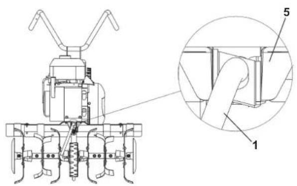
2B
natural_image
Technical line drawing of a mechanical tool or machine component with no visible text or symbols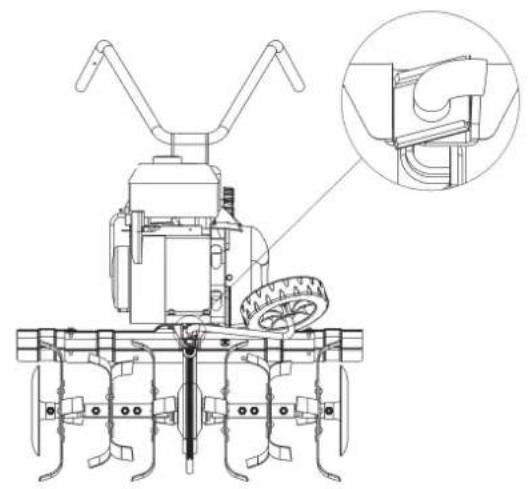
natural_image
Technical line drawing of a mechanical tiller with a close-up inset showing the blade and wheel assembly (no text or symbols)33

13
natural_image
Technical line drawing of a mechanical device with labeled components (no readable text or symbols)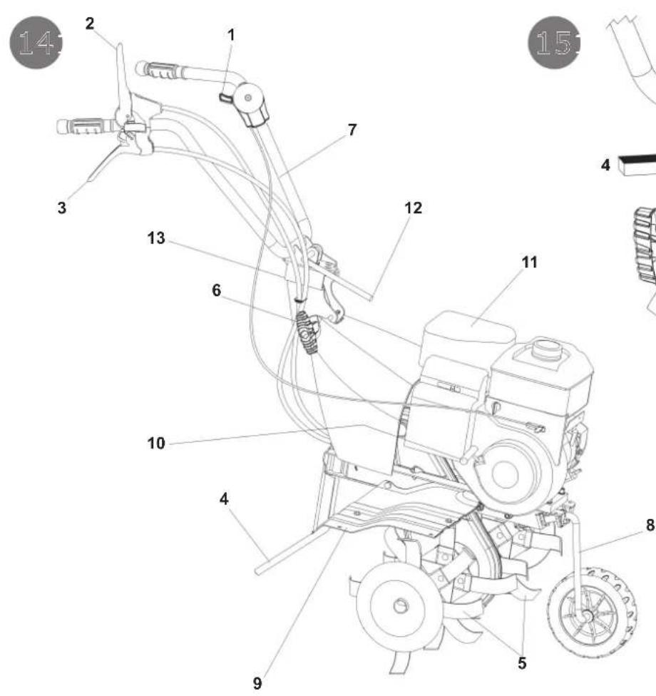
natural_image
Diagram of a mechanical lever mechanism with curved arrows indicating motion (no text or symbols)Etichetta rotazione stegola
Sticker handlebar rotation
Aufkleber Holmdrehung
Plaquette rotation mancherons
Etiqueta rotacion de manilla
Nalepka o vrtenju krmilne ročice
Oznaka za rotaciju drške za upravljanje
Naklejka obrót kierownicy
Etiqueta de rotação do guiador

Read the instructions manual before operating on the machine - Danger tiller rotation
Forward and reverse drive label
Plaquette acceleration
Label accelerator
-
Manufacturer identification
-
Model
-
Product identification code
-
Item serial number
-
Mass
-
Year / Month
-
Motor power
-
Type of product
DE
Translation of original user instructions
List of contents
Introduction
Conditions of use
Safety measures
Instructions for operating
Transport
Assembly
Regulating
Maintenance
Technical Details
Noise
Accessories
Fault

Serious risk for operator and bystander safety.
Introduction
Dear Customer:
Thank you for your trust in purchasing our products. We wish you to enjoy using our machines.
The following working instructions have been issued to ensure you a reliable operation from the beginning. If you carefully follow such information the machine will operate with complete satisfaction have a long service life. Our machines are tested under the most severe conditions before being put into production and are subject to strict continuous tests during manufacturing stages.
This unit has been tested in the country of origin by independent testing authorities in accordance with strict work norms and safety standards.
When required, only original spare parts must be used to maintain guaranteed function and safety levels.
The operator forfeits any claims which may arise, if the machine shows to be fitted with components other than original spare parts. Subject to changes in design and construction without notice.
For any questions or further information and spare part orders, we need to be informed of the unit serial number printed on the side of the machine.
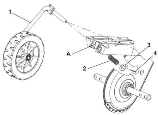
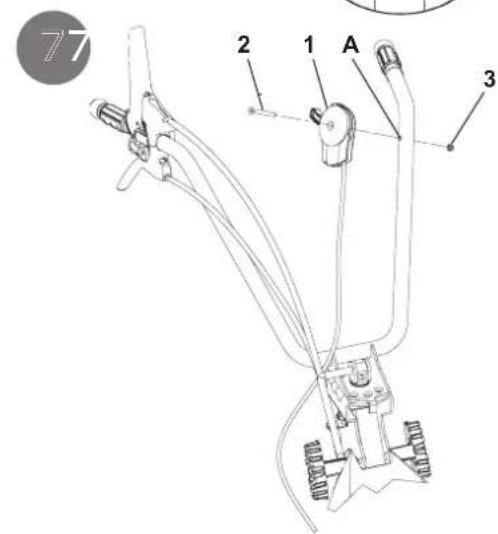
IDENTIFICATION DATA (Fig. 1)
The label showing the unit references and the serial number is placed in the front frame side of it and it is shown by an arrow. Note - Always state your motor cultivator serial number when you need Technical Service or Spare Parts.
CONDITIONS OF USE AND LIMITATIONS OF USE
This motor-hoe is designed and built to hoe the land. The motor-hoe must only be used with original equipment and spares. Any use other than those described above is prohibited and will involve, in addition to cancellation of the warranty, serious risk for the operator and bystanders.
SAFETY PRECAUTIONS
Attention: Before assembly and putting into operation, please read the operating instruction carefully. Persons not familiar with these instructions should not use the machine.

1- Persons who are not familiar with the operating manual, as well as children, adolescents under the age of 16 and persons under the influence of alcohol, drugs or medication must not operate the mower.
2 - The unit was designed in order to be used by 1 trained operator only. The person using the mower is responsible for any accidents involving other persons or their property. When operating the machine, the user should ensure that no others, particularly children, are standing in the area (10 mt.).
3 - Before starting to mill, remove any foreign bodies from the soil. Work only in daylight or in good artificial light.
4 - Do not start the machine if standing in front of the rotary cutter, neither get near the machine when

working. If pulling the starter short rope, the rotary cutter and the machine have to standstill (if rotation is experienced, take action on the belt stretcher control nut).
5 - During working operations, for protection purposes, it is recommended to wear technical/strong shoes and long trousers. Be careful, because when machine is operating the danger to be wounded in the toes or feet is really high. Walk, never run with the machine.
6 - During the machine transport and all the maintenance, cleaning, equipment change operations, the engine must be switched off.
7 - Before leaving the machine, please switch the engine off.
8 - Do not switch the machine on in closed rooms/areas where you can have carbon monoxide exhalations.
9 - WARNING !! The petrol/gasoline is highly inflammable. Store fuel only in containers specifically designed for he storage of such materials. Don't fill the tank neither in closed areas, nor when engine is on, don't smoke and be careful to the petrol/gasoline loss from the tank. In case of leak, don't try to switch the engine on but move the machine away from the area in order to avoid ignition source until the gasoline vapours fade away. Re-place the tank caps and the gasoline box. Never open the cap of the fuel tank, or add fuel, while the engine is running or the unit is hot.
10 - Keep attention to the exhaust pipe. The parts near the pipe can reach 80°C. Replace the defective and/or worn out silencers Burn hazards !!!.
11- Don't use the motor hoe on steep slopes: it could overturn!. On slope it is recommended to work crosswise, neither in slope nor in descent and be vary careful during any change of direction.
12 - Before putting the machine into operations, check it visually and make sure all the accident prevention measures are working. It is absolutely forbidden to exclude and/or to tamper with them. Replace worn or damaged elements.
13 - In case the machine is incorrectly used, and/or the repairs are performed by non-authorized technical staff, and/or fitted by spare parts other than original ones: any use other than that described above is prohibited and will involve the cancellation of the warranty and the refuse all responsibility from the manufacturer.
SAFETY FEATURE (Fig. 14) All motor-hoes are provided with a safety feature which acts. The device causes the transmission to disconnect automatically anytime the respective control levers are released (2 Forward speed – 3 Reverse speed).
NOTES ON HOW TO WORK WITH THE MOTOR-HOE With the engine running, rest the tines on the ground, and firmly holding the motor-hoe, insert the spur into the soil. Lower the clutch lever on the handlebar to allow the disks to bite into the soil. The motor-hoe will move forwards when the handlebars are used to slightly lift the disks. The spur arm must always remain in the soil during work. Uses: Light or medium textured soil working. Soil working (hoeing/breaking-up). Soil tillage (weeding). Ploughing in compost or fertilizers, etc. Attention: The motor-hoe is unsuitable for working in soils covered by thick grass/lawns. It is also unadvisable to use the implement on stony soils.
TRANSPORT A forklift truck should be used to move the machine. The forks should be opened as far as possible and inserted into the pallet. The weight of the machine is given on the Manufacturer's data plate together with the other technical information. Motor-hoe can be transported to given place by means of transport wheel (Fig 14 part. 8). Switch off the engine before transporting the machine.
HOW TO ASSEMBLE YOUR MOTOR-HOE Unless otherwise agreed, the motor-hoe is delivered disassembled and placed in a packing case. For assembly to be completed, the step by step procedure is as follows :
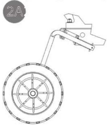
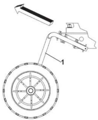
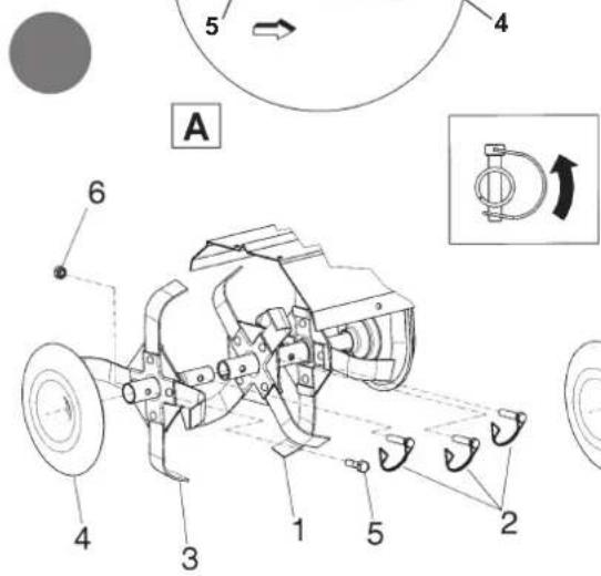
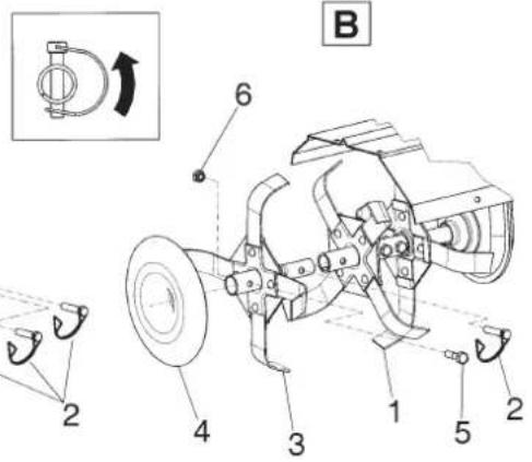
TRANSFER WHEEL (Fig. 2 A and 2 B) Take from the packing box the support wheel complete with wheel (1) and insert it in the front seat of the
frame (A). Fit the spring (2) and secure it with the washer (3) and the cotter pin (4) into the housing hole. The wheel support is in the transport position as shown in Fig. 2A. To shift to work position pull it towards the wheel support (1) and turn it to the right until it stops. See fig. 2 B. The spring, washer and cotter pin can be found inside the bag accessories.
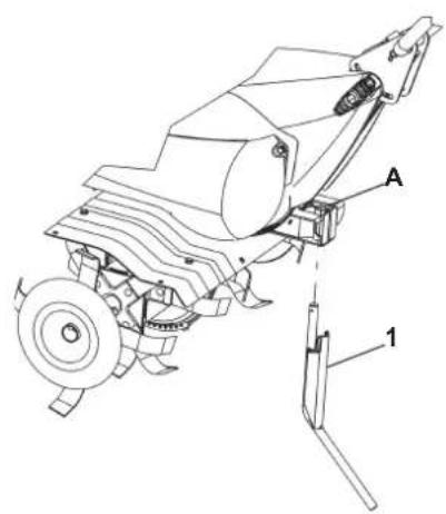
SPUR (Fig. 3) Insert the spur (1) in correspondence of the hole of the frame (A). Secure with washer (2) and with the R pin (3) you can find in the accessories bag.
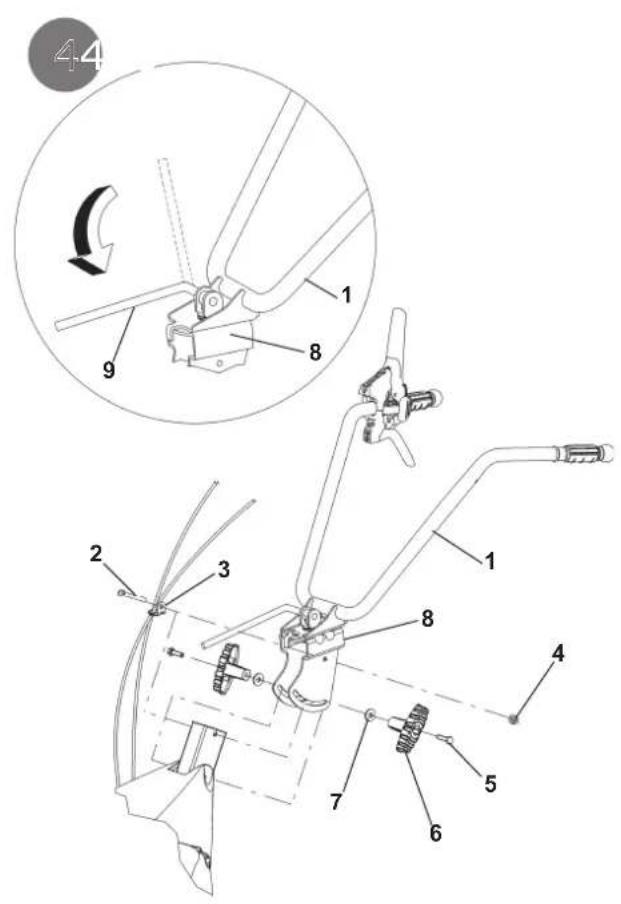
HANDLEBAR ASSEMBLY (Fig. 4): To assemble the handlebar (1) on the tiller frame, perform the following steps:
In the upper hole to pass the screw (2) in the grommet (3) with already entered the control cables and then secure it with the nut (4). Use the lower slot screws (5) inside of the knobs (6) and washers (7). All these pieces for mounting handlebar with the exception of the grommet (3), are present in the envelope accessories inside the packaging box. To fit definitively the handlebar (1) to the corresponding support (8) you need to lower the lever (9).
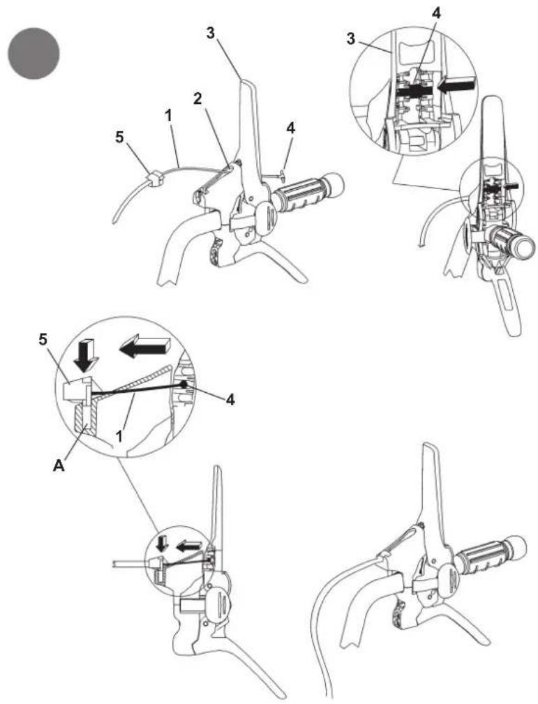
CONTROL CABLES ASSEMBLY (Fig. 5 - Fig. 6): The two cables are already installed on the unit and must be connected to the corresponding levers.
FORWARD (Fig. 5) Insert the wire (1) with the terminal T-slot (2) of the lever (3) pre-mounted on the handlebar. Place the cylindrical terminal (4) into the seat of the lever (3) and give a firm tug to lock it. Then pinch the wire adjuster (5) into the seat (A) of the lever, by doing downward pressure.
REVERSE (Fig. 6): Insert the wire (1) with the cylindrical terminal into the slot (2) of the lever (3) pre-assembled on the handlebar. Place the cylindrical terminal (4) into the central seat (A) of the lever (3) and give a firm tug to lock it. Then insert the log thread (5) into place (B) of the lever.
THROTTLE ASSEMBLY (Fig. 7) The throttle wire is already mounted both on the engine inside the throttle device (1). Such a device is fastened in the hole (A) of the handlebar with the screw (2) and locked with the nut (3).
ASSEMBLY THE HOE TILLER (Fig. 8) Clean the tiller hubs and the tiller-shaft; apply some grease to make mounting and tiller removal easier in the future. B&S 800 / Kohler SH265 engine model (fig. 8/A): insert the rotavator (1) making attention the knives have the sharpening side turned to the front part of the machine and block the rotavator with two pins (2) assembling the extra-wide tines (3) and fix it with 1 pin as well (2). Then block the tree saver disk (4) with 1 screw (5) and 1 nut (6). Repeat the same operation for the rotavator on the other machine side. Other engines (fig. 8/B): the rotavator (1) is already assembled with nr. 2 screws and the same number of nuts so you only need to assemble the extra-wide tines (3) and block it with pin (2) and fix the tree saver disk (4) with screw (5) and nut (6). Repeat the same operation for the rotavator on the other machine side. N.B. = please note it is necessary to assemble the pin as shown in the picture placed in the centre of the page, i.e., with the protection stopping device turned in the same direction the rotavators are turning, in order to avoid the pin to open during working operations.
ASSEMBLY OF THE TINES GUARD (Fig. 8 A) Only tillers with cm. 75 rotavator. Remove the packing box enlargement widening tines guard (1) with pre-assembled screws (2). Mount it by aligning the screws (2) with cage nuts (3). Repeat the same operation with the widening tines of the other side of the rotavator.
CONTROL ADJUSTMENT : (Fig. 9) Attention! The rotavator has to start working only after having operated on the control levers. Such operation can be performed by acting on the handlebar cables (1 Forward speed) 2 (Reverse speed) register. Furthermore the lever controlling the digging speed (3) should start the rotavator only after having performed half its way. When the lever (3) and the lever (4) are held together, i.e. on working operation, the belt stretcher load-spring for forward speed (5e 6) should be extended for about 8-10 mm. If the handlebar register is not enough to obtain any conditions, please go on another adjustment.
FORWARD: screw or unscrew the adjuster (7) or (8) on the wire (1).
REVERSE: screw or unscrew the adjuster (9) or (10) on the wire (2).
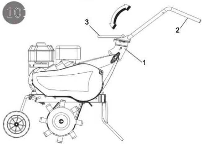
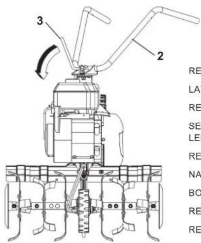
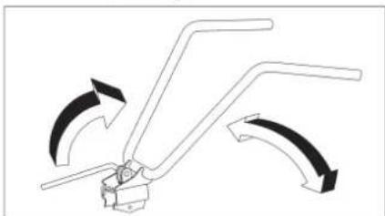
HANDLEBAR ADJUSTMENT (Fig. 10) The motor-hoe handlebar can be both side and height adjusted. Before starting any work it is a good standard operating procedure to adjust the handlebar to the operator's requirements so that the machine could be easily handled.
LATERAL ADJUSTMENT : The lateral inclination of the handlebar allows the operator to keep off the cultivated ground and not to squash the vegetation around. Go on raising the lever (3) to unlock the handlebar (2) from the support (1). Turn the handlebar to the desired part and lower the lever (3) to lock it.
HEIGHT ADJUSTMENT : in order to unlock the handlebar (2) you need to turn the handles (4) to loosen them .
Raise or lower the handlebar in the desired position (the standard adjustment is at the sides height/level). To settle the right position, tighten the 2 handles.
INSTRUCTIONS Following the assembly & adjustment operations the motor-hoe is ready to start working.
- Adjust the handlebar to the requested position/height (see fig. 10).
- Before switching the engine on, carefully check if the motor-hoe is in perfect good repair.
- Attention: the motor-hoe is delivered without the oil into the engine. The tank has got a capacity for about 0,5 kg. and should be filled in up to the indicated level. In any case the operator should always carefully read the engine instructions manual.
- Do not change the calibration of the speeds control rotation device of the engine in order not to over-speed it.
IMPORTANT : at the first use of the machine it is absolutely necessary to verify that inside the chassis to be present the lubrication oil. Do no start the unit/machine on before having done such control.
- When you have finished the assembly, switch the motor-hoe on and check, bringing the accelerator to stop position, the engine to shut completely down.
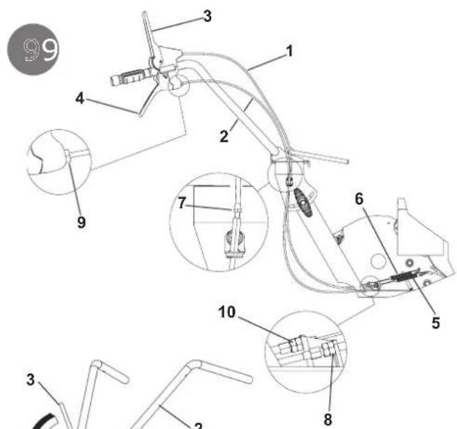
- How to switch the engine on (Fig.14): Open the fuel cap (for the engine equipped like this), push to START the accelerator lever on the handlebar (1). If the engine is cold, operate the starter device on the carburettor, bring the starter handle (10) and pull energetically.
When the engine is on, after some bursts/bangs, put the starter again at rest position.
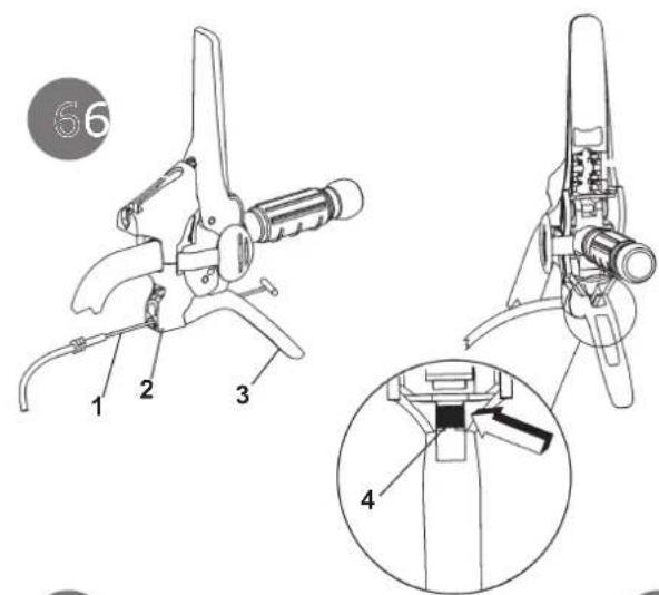
- Forward speed (fig.11): Grip the handlebars (1) and press the safety device (2) which is preventing the accidental tines connection. Lower the forward lever (3) all its way long.
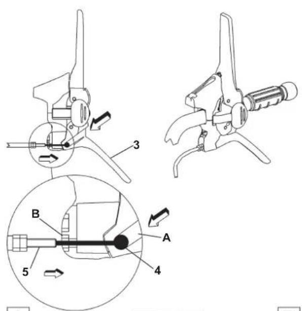
- Reverse speed (Fig. 12): Grip the handlebars (1) and press the safety device (2) which is preventing the accidental tines connection. Pull the reverse lever (3) all its way long.
The present machine has been projected in order to lower to the minimum the vibrations and noise levels. Anyhow we can advise you to stop working any now and then in case you would need to perform/work for a long period.
- Stop working operation : To stop the work, switch the engine off, bring the accelerator lever (Fig. 14 part 1) into stop position.
EN
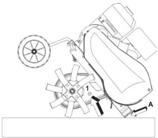
GEAR BOX OIL CHANGE (only when engine/gear box is working using a hot device) (Fig. 13) As a general rule the oil should be changed after every 100 work hours (oil viscosity SAE 80). To change oil: a) Remove the spur. b) Unscrew the screw cap. - c) Tilt the machine and intake the oil through a syringe. - d) Pour in about 0,5 l. of new oil. Tilt the machine to check that level is correct. The oil should begin to flow from the hole just before the machine touches the ground (with point A) - e) Replace the filler screw cap (1).
ATTENTION! The used oil must not be drained into the sewer system or waterworks. In order to prevent any pollution to the water-table. Most garages have used oil deposits, or use the authorized deposits according to your local authority regulations.
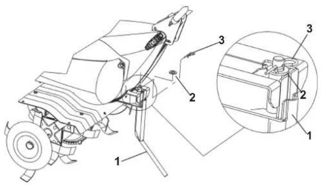
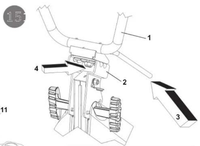
GARAGING AND SCHEDULED MAINTENANCE (Fig. 15) Keep attention that all the nuts, screws and bolts are tightened in order to guarantee a good machine working on safety conditions. Leave the machine to cool before garaging anyhow don't room it if the tank still contains some fuel as the vapours could reach some blazes or sparks. The fuel tank is to be drained outdoors only. To lower the fire danger, keep the engine, the silencer and the fuel area free from leaves, grass or greasy substances. Periodically check the tightness of the handlebar (1) to the support (2). If the tightening is not guaranteed, please lower the lever (3) and tighten the nut (4).
DESCRIPTION OF CONTROLS (Fig. 14) 1. Throttle lever - 2. Hoeing gear control lever (safety feature) - 3. Reversing lever - 4. Tilling adjustment spur (single position) - 5. Cultivator blade (with enlargement) - 6. Knobs handlebar/frame - 7. Handlebar - 8. Transport Wheel - 9. Hoe shield - 10. Pull-out handle (self-winding device) 11. Motor - 12. Lock/release lever for handlebar - 13. Handlebar support
TECHNICAL SPECIFICATION Engine: consult the specific publication for information. Transmission: primary by belt, secondary by chain. Tiller: fitted with interchangeable hoes. Working width 50 cm and 75 cm. The highest speed of rotation of the tiller is about 140 R.P.M. Transmission: single speed or single speed + reverse speed. Max length: 1,35 m. Max width: 0,50 - 0,75 m. Height: 1,00 m. Package dimensions: long 80 cm - wide 53 cm - high 69 cm.
NOISE AND VIBRATION LEVEL Measured sound pressure level with En709, Leq = 88.5 dB (A), with a uncertainty value K = ±0.8 dB (A). Measured sound power level with En709, Lwa = 96.1 dB (A), with a uncertainty value K = ±0.9 dB (A).
Handlebar vibration in compliance with EN 709 and ISO 5349. Level max detected = 5,39 m/s ^2 , uncertainty value K = ±0,36 m/s ^2 .
ACCESSORIES: Ridging plough and De-Thatcher.
TROUBLESHOOTING

Before performing any maintenance and clearing work operation, please take the spark-plug cap off.!
| FAULT FAULT CLEARANCE | |
| The engine does not start Check the fuel level, if necessary | refuel. |
| Check the throttle to be on START position. | |
| Check the spark-plug connector to be properly attached. | |
| Check the spark-plug condition and if necessary replace it. | |
| Check the fuel valve to be in the opened position( only for the models showing such feature). | |
| The engine power goes down | The air filter is dirty – please clean it. |
| Check if any stone or soil/vegetation residue is stopping the tines rotation, in case clean them. | |
| The tines are not rotating Adjust the transmission cables registers. | |
| In case you are not able to remedy the defect/damage according to a.m. table, please contact an authorized service center only . | |
POLITYKA GWARANCYJNA MULTIPOWER QUALITY AND SERVICES S.R.L.
Multipower Quality & Services
Tel. +39-0522-221128 - Fax. +39-0522-221136 - Website: www.multi-power.it
Multipower Quality & Services
Tel. +39-0522-221128 - Fax. +39-0522-221136 - Website: www.multi-power.it