
YAS-706 - Soundbar YAMAHA - Free user manual and instructions
Find the device manual for free YAS-706 YAMAHA in PDF.

| Product Type | Soundbar with wireless subwoofer |
| Model | YAS-706 (main unit: YAS-CU706, subwoofer: NS-WSW121) |
| Total Power Output | Approx. 60 W (estimated) |
| Dimensions (Main Unit) | Approx. 950 x 62 x 110 mm (W x H x D) (estimated) |
| Weight (Main Unit) | Approx. 3.5 kg (estimated) |
| Dimensions (Subwoofer) | Approx. 200 x 350 x 400 mm (W x H x D) (estimated) |
| Weight (Subwoofer) | Approx. 7 kg (estimated) |
| Power Supply | 230 V~ 50/60 Hz |
| Power Consumption | Approx. 40 W (operating), less than 0.5 W in standby |
| HDMI Inputs | 2 inputs (HDMI IN 1, HDMI IN 2) + 1 ARC output |
| Audio Inputs | 1 optical (TV), 1 coaxial, 1 analog stereo |
| Network Connectivity | Ethernet (RJ45), Wi-Fi (IEEE 802.11 b/g/n) |
| Bluetooth | Version 2.1 + EDR, A2DP profile |
| Audio Technologies | Air Surround Xtreme, Clear Voice, Bass Extension, Dolby Pro Logic II |
| Supported Audio Formats | Dolby Digital, Dolby Digital Plus, Dolby TrueHD, DTS Digital Surround, DTS-HD, PCM |
| Network Functions | MusicCast, AirPlay, Internet radio, playback from media server |
| Maintenance and Cleaning | Dry, clean cloth. Do not use chemical solvents. |
| Safety | Do not expose to water or moisture. Unplug during thunderstorms. Keep out of reach of children. |
| Spare Parts and Repairability | Have all repairs performed by a qualified technician. Contact Yamaha service. |
| Supplied Accessories | Remote control, AAA batteries (x2), optical digital audio cable (1.5 m), mounting template, spacers, repeater cover, CD-ROM (instruction manual) |
Frequently Asked Questions - YAS-706 YAMAHA
User questions about YAS-706 YAMAHA
0 question about this device. Answer the ones you know or ask your own.
Ask a new question about this device
Download the instructions for your Soundbar in PDF format for free! Find your manual YAS-706 - YAMAHA and take your electronic device back in hand. On this page are published all the documents necessary for the use of your device. YAS-706 by YAMAHA.
USER MANUAL YAS-706 YAMAHA
[YAS-CU706+NS-WSW121]

natural_image
Two simple rectangular shapes with white outlines on a gray background, no text or symbols present.For more detailed information, refer to the Owner's Manual in the CD-ROM. Caution: Do not attempt to play this CD-ROM in an audio player.
IMPORTANT SAFETY INSTRUCTIONS

CAUTION
RISK OF ELECTRIC SHOCK DO NOT OPEN

CAUTION: TO REDUCE THE RISK OF ELECTRIC SHOCK, DO NOT REMOVE COVER (OR BACK). NO USER-SERVICEABLE PARTS INSIDE. REFER SERVICING TO QUALIFIED SERVICE PERSONNEL.
• Explanation of Graphical Symbols
The lightning flash with arrowhead symbol, within an equilateral triangle, is intended to alert you to the presence of uninsulated "dangerous voltage" within the product's enclosure that may be of sufficient magnitude to constitute a risk of electric shock to persons.

The exclamation point within an equilateral triangle is intended to alert you to the presence of important operating and maintenance (servicing) instructions in the literature accompanying the appliance.
I Read these instructions.
2 Keep these instructions.
3 Heed all warnings.
4 Follow all instructions.
5 Do not use this apparatus near water.
6 Clean only with dry cloth.
7 Do not block any ventilation openings. Install in accordance with the manufacturer's instructions.
8 Do not install near any heat sources such as radiators, heat registers, stoves, or other apparatus (including amplifiers) that produce heat.
9 Do not defeat the safety purpose of the polarized or grounding-type plug. A polarized plug has two blades with one wider than the other. A grounding type plug has two blades and a third grounding prong. The wide blade or the third prong are provided for your safety. If the provided plug does not fit into your outlet, consult an electrician for replacement of the obsolete outlet.
10 Protect the power cord from being walked on or pinched particularly at plugs, convenience receptacles, and the point where they exit from the apparatus.
11 Only use attachments/accessories specified by the manufacturer.
12 Use only with the cart, stand, tripod, bracket, or table specified by the manufacturer, or sold with the apparatus. When a cart is used, use caution when moving the cart/apparatus combination to avoid injury from tip-over.
13 Unplug this apparatus during lightning storms or when unused for long periods of time.
14 Refer all servicing to qualified service personnel. Servicing is required when the apparatus has been damaged in any way, such as power-supply cord or plug is damaged, liquid has been spilled or objects have fallen into the apparatus, the apparatus has been exposed to rain or moisture, does not operate normally, or has been dropped.

FCC INFORMATION (for US customers)
I IMPORTANT NOTICE: DO NOT MODIFY THIS UNIT!
This product, when installed as indicated in the instructions contained in this manual, meets FCC requirements. Modifications not expressly approved by Yamaha may void your authority, granted by the FCC, to use the product.
2 IMPORTANT: When connecting this product to accessories and/or another product use only high quality shielded cables. Cable/s supplied with this product MUST be used. Follow all installation instructions. Failure to follow instructions could void your FCC authorization to use this product in the USA.
3 NOTE: This product has been tested and found to comply with the requirements listed in FCC Regulations, Part 15 for Class "B" digital devices. Compliance with these requirements provides a reasonable level of assurance that your use of this product in a residential environment will not result in harmful interference with other electronic devices. This equipment generates/uses radio frequencies and, if not installed and used according to the instructions found in the users manual, may cause interference harmful to the operation of other electronic devices.
Compliance with FCC regulations does not guarantee that interference will not occur in all installations. If this product is found to be the source of interference, which can be determined by turning the unit "OFF" and "ON", please try to eliminate the problem by using one of the following measures:
Relocate either this product or the device that is being affected by the interference.
Utilize power outlets that are on different branch (circuit breaker or fuse) circuits or install AC line filter/s.
In the case of radio or TV interference, relocate/reorient the antenna. If the antenna lead-in is 300 ohm ribbon lead, change the lead-in to coaxial type cable.
If these corrective measures do not produce satisfactory results, please contact the local retailer authorized to distribute this type of product. If you can not locate the appropriate retailer, please contact Yamaha Corporation of America A/V Division, 6600 Orangethorpc Avenue, Buena Park, CA 90620, USA.
The above statements apply ONLY to those products distributed by Yamaha Corporation of America or its subsidiaries.
NOTICE
This equipment has been tested and found to comply with the limits for a Class B digital device, pursuant to part 15 of the FCC Rules. These limits are designed to provide reasonable protection against harmful interference in a residential installation. This equipment generates, uses and can radiate radio frequency energy and, if not installed and used in accordance with the instructions, may cause harmful interference to radio communications. However, there is no guarantee that interference will not occur in a particular installation. If this equipment does cause harmful interference to radio or television reception, which can be determined by turning the equipment off and on, the user is encouraged to try to correct the interference by one or more of the following measures:
- Reorient or relocate the receiving antenna.
- Increase the separation between the equipment and receiver.
- Connect the equipment into an outlet on a circuit different from that to which the receiver is connected.
- Consult the dealer or an experienced radio/TV technician for help.
This equipment complies with FCC/IC radiation exposure limits set forth for an uncontrolled environment and meets the FCC radio frequency (RF) Exposure Guidelines and RSS-102 of the IC radio frequency (RF) Exposure rules. This equipment should be installed and operated keeping the radiator at least 20cm or more away from person's body.
This transmitter must not be co-located or operated in conjunction with any other antenna or transmitter.
- This device complies with Part 15 of FCC Rules and Industry Canada licence-exempt RSS standard(s).
- Operation is subject to the following two conditions: 1) this device may not cause harmful interference, and 2) this device must accept any interference received including interference that may cause undesired operation.
FOR CANADIAN CUSTOMERS
To prevent electric shock, match wide blade of plug to wide slot and fully insert. CAN ICES-3 (B)/NMB-3 (B)
CAUTION: READ THIS BEFORE OPERATING YOUR UNIT.
To assure the finest performance, please read this manual carefully. Keep it in a safe place for future reference.
2 Install this sound system in a well ventilated, cool, dry, clean place - away from direct sunlight, heat sources, vibration, dust, moisture, and/or cold. For proper ventilation, allow the following minimum clearances.
Top: 5 cm (2 in), Rear: 5 cm (2 in), Sides: 5 cm (2 in)
3 Locate this unit away from other electrical appliances, motors, or transformers to avoid humming sounds.
4 Do not expose this unit to sudden temperature changes from cold to hot, and do not locate this unit in an environment with high humidity (i.e. a room with a humidifier) to prevent condensation inside this unit, which may cause an electrical shock, fire, damage to this unit, and/or personal injury.
5 Avoid installing this unit where foreign object may fall onto this unit and/or this unit may be exposed to liquid dripping or splashing. On the top of this unit, do not place:
- Other components, as they may cause damage and/or discoloration on the surface of this unit.
- Burning objects (i.e. candles), as they may cause fire, damage to this unit, and/or personal injury.
- Containers with liquid in them, as they may fall and liquid may cause electrical shock to the user and/or damage to this unit.
6 Do not cover this unit with a newspaper, tablecloth, curtain, etc. in order not to obstruct heat radiation. If the temperature inside this unit rises, it may cause fire, damage to this unit, and/or personal injury.
7 Do not plug in this unit to a wall outlet until all connections are complete.
8 Do not operate this unit upside-down. It may overheat, possibly causing damage.
9 Do not use force on switches, knobs and/or cords.
10 When disconnecting the power cable from the wall outlet, grasp the plug: do not pull the cable
11 Do not clean this unit with chemical solvents; this might damage the finish. Use a clean, dry cloth.
12 Only voltage specified on this unit must be used. Using this unit with a higher voltage than specified is dangerous and may cause fire, damage to this unit, and/or personal injury. Yamaha will not be held responsible for any damage resulting from use of this unit with a voltage other than specified.
13 To prevent damage by lightning, keep the power cable and outdoor antennas disconnected from a wall outlet or this unit during a lightning storm.
14 Do not attempt to modify or fix this unit. Contact qualified Yamaha service personnel when any service is needed. The cabinet should never be opened for any reasons.
15 When not planning to use this unit for long periods of time (i.e. vacation), disconnect the AC power plug from the wall outlet.
16 Be sure to refer to the "Troubleshooting" section of the Owner's Manual in the CD-ROM for common operating errors before concluding that this unit is faulty.
17 Before moving this unit, press Ⓑ to set it to standby mode and disconnect the AC power plug from the wall outlet.
18 Condensation will form when the surrounding temperature changes suddenly. Disconnect the power cable from the outlet, then leave this unit alone.
19 When using this unit for a long time, this unit may become warm. Turn the power off, then leave this unit alone for cooling.
20 Install this unit near the AC outlet and where the AC power plug can be reached easily.
21 The batteries shall not be exposed to excessive heat such as sunshine, fire or the like. When you dispose of batteries, follow your regional regulations.
22 Excessive sound pressure from earphones and headphones can cause hearing loss.
23 Keep the product out of reach of children to avoid them swallowing small parts.
24 Do not put a hand or foreign object into the port on the subwoofer.
25 When moving the subwoofer, do not hold the port, as it may cause personal injury and/or damage to this unit.
26 Do not place a fragile object near the port of the subwoofer. If the object falls as a result of the air pressure, it may cause personal injury and/or damage to the subwoofer and the object.
This unit is not disconnected from the AC power source as long as it is connected to the wall outlet, even if this unit itself is turned off by Ⓐ. This state is called the standby mode. In this state, this unit is designed to consume a very small quantity of power.
WARNING
TO REDUCE THE RISK OF FIRE OR ELECTRIC SHOCK, DO NOT EXPOSE THIS UNIT TO RAIN OR MOISTURE.
Do not use this unit within 22 cm (9 inches) of persons with a heart pacemaker implant or defibrillator implant.
Radio waves may affect electro-medical devices.
Do not use this unit near medical devices or inside medical facilities.
The name plate for YAS-CU706 is located on the bottom of the unit.

Caution
Do not touch the surface marked with this label. The surface may become hot during operation.
■Notes on remote controls and batteries
- Do not spill water or other liquids on the remote control.
- Do not drop the remote control.
- Do not leave or store the remote control in the following conditions:
- places of high humidity, such as near a bath
- places of high temperatures, such as near a heater or stove
- places of extremely low temperatures
- dusty places
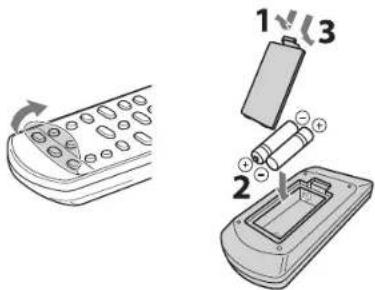
- Insert the battery according to the polarity markings (+ and -).
- If the batteries grow old, the effective operation range of the remote control decreases considerably. If this happens, replace the batteries with two new ones as soon as possible.
- If the batteries run out, immediately remove them from the remote control to prevent an explosion or acid leak.
- If you find leaking batteries, discard the batteries immediately, taking care not to touch the leaked material. If the leaked material comes into contact with your skin or gets into your eyes or mouth, rinse it away immediately and consult a doctor. Clean the battery compartment thoroughly before installing new batteries.
- Do not use old batteries together with new ones. This may shorten the life of the new batteries or cause old batteries to leak.
- Do not use different types of batteries (such as alkaline and manganese batteries) together. Danger of explosion may happen if batteries are incorrectly replaced. Specification of batteries may be different even though they look the same.
- Before inserting new batteries, wipe the compartment clean.
- Keep batteries away from children. If a battery is accidentally swallowed, contact your doctor immediately.
- When not planning to use the remote control for long periods of time, remove the batteries from the remote control.
- Do not charge or disassemble the supplied batteries.
For more detailed information, refer to the Owner's Manual on the CD-ROM. To view the Owner's Manual, click on "English" in the screen displayed automatically when you insert the CD-ROM into your PC, or click on the model name if the screen to select models is displayed, and then click on "English" in the next screen. Then, follow the onscreen instructions.
If the screen is not displayed automatically, open the "index.html" in the CD-ROM.
Caution: Do not attempt to play this CD-ROM in an audio player.
The Owner's Manual contained in the CD-ROM can be downloaded from the following website.
http://download.yamaha.com/
Contents
PREPARATION
Supplied items 7
Part names and functions 8
Installation 11
Connecting the unit to a TV and set-top box.... 13
Turning on the unit.... 14
PLAYBACK
Operations....15
NETWORKS
Networks 19
Network functions and the MusicCast CONTROLLER app ....19
Connecting to a network 19
About this Quick Start Guide
This Quick Start Guide provides basic setup to use the unit and feature of the unit. For more information, refer to the Owner's Manual in the supplied CD-ROM.
In this booklet, iOS and Android mobile devices are collectively referred to as "mobile devices". The specific type of mobile device is noted in explanations as needed.
NOTE
This indicates precautions for use of the product and its feature limitations.
HINT
This indicates supplementary explanations for better use.
Supplied items
Make sure you have received all of the following items.
The YAS-706

Center unit (YAS-CU706) Wireless subwoofer

(NS-WSW121)
Supplied accessories
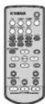
Remote control Batteries x 2

(AAA, R03, UM4)
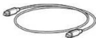
Optical digital audio cable
(1.5 m [4.9 ft])
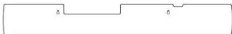
Mounting template
Use when mounting the unit on a wall.
See page 11 in the Owner's Manual.

Spacers × 2
Use when mounting the unit
on a wall. See page 11 in the Owner's Manual.
Cover (for the TV remote repeater)
See page 11 in the Owner's Manual.
- Quick Start Guide • MusicCast Setup Guide • Owne
Preparing the remote control
Peel off the protection sheet before use.
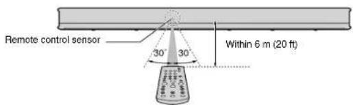
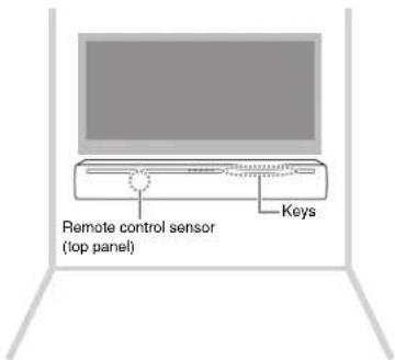
Operating range of the remote control
Operate the remote control within the range as shown below. When the unit is mounted on a wall, point the remote control at the remote control sensor on the top panel (p. 12).
Part names and functions
Center unit (front panel/top panel)
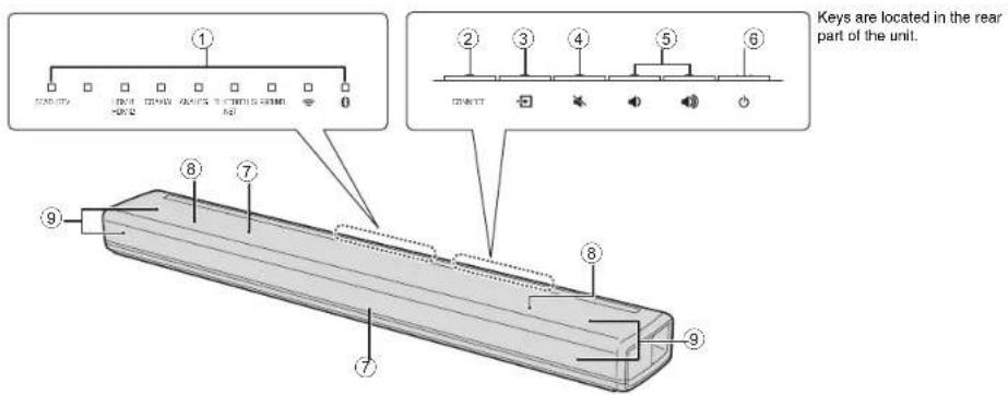
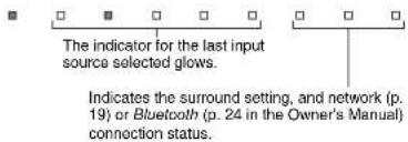
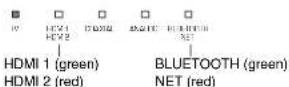
①Indicators
The indicators on the top panel flash or glow, to show the operation and setting status.
In this manual, illustrations of the nine in-line indicators are used for explanation as necessary.
Use to connect the unit to a network using the MusicCast CONTROLLER app (p. 20).
③ (input) key
Select an input source to be played back (p. 15).
④ (minute) key
Mute the audio output. Press the key again to unmute (p. 17).
⑤/◄(volume +/-) keys
Adjust the volume (p. 17).
⑥ (power) key
Turn on or off the unit (p. 15).
HINT
- The unit may automatically turn off when the auto power standby function is enabled (p.50 in the Owner's Manual).
⑦ Remote control sensors
Receive infrared signals from the remote control of the unit (p. 7) or TV's remote control (p. 12).
The remote control sensors are located on the front panel and on the top panel of the unit (p. 11).
⑧Dual built-in subwoofers
The built-in subwoofers are located in the top part of the unit.
⑨Speakers
Center unit (rear panel)
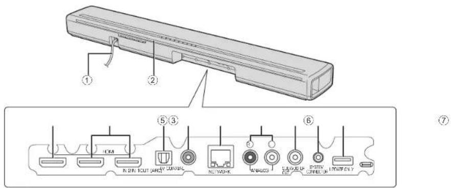
①Power cable
For connecting to an AC wall outlet (p. 13).
②TV remote repeater
Used to transmit signals from the TV's remote control, received by the unit's remote control sensor, to the TV (p. 12).
③HDMI OUT (ARC) jack
For connecting to an HDMI-compatible TV and outputting video/audio signals (p. 13).
④HDMI IN 1 and 2 jacks
For connecting HDMI-compatible playback devices such as a set-top box, a BD/DVD player, and a game console (p. 13).
⑤TV input jack
For connecting to a TV with an optical digital audio cable (p. 13).
⑥COAXIAL Input jack
For connecting to a playback device, such as a BD/DVD player, with a coaxial digital audio cable (p. 13 in the Owner's Manual).
⑦NETWORK jack
For connecting to a network with a network cable (p. 26 in the Owner's Manual).
⑧ANALOG input jacks
For connecting to an external device with a stereo cable (p. 12, 14 in the Owner's Manual).
⑨SUBWOOFER OUT jack
For connecting to the supplied subwoofer using a wired connection (p. 15 in the Owner's Manual).
⑩ SYSTEM CONNECTOR Jack
For connecting to the supplied subwoofer using a wired connection (p. 15 in the Owner's Manual).
⑪UPDATE ONLY jack
Use to update this unit's firmware (p. 53 in the Owner's Manual).
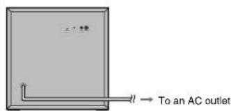
Subwoofer (rear panel)
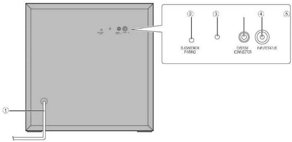
①Power cable
For connecting to an AC wall outlet (p. 13).
②SUBWOOFER PAIRING key
Used to pair the center unit with the subwoofer manually (p. 62 in the Owner's Manual). Use a pin or other pointed object to press this key.
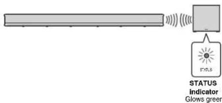
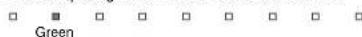
③STATUS indicator
Shows subwoofer's connection status (p. 14). Glows green: Power on Glows red: Power off
④ SYSTEM CONNECTOR jack
For connecting to the center unit using a wired connection (p. 15 in the Owner's Manual).
⑤INPUT jack
For connecting to the center unit using a wired connection (p. 15 in the Owner's Manual).
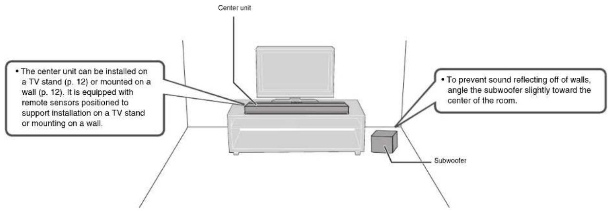
Installation
Position the center unit and subwoofer as shown below with installation.
Cautlons
- Be sure to install the center unit on a large, stable stand where it does not fall subject to vibrations, such as from an earthquake, and where it is out of the reach of children.
- Do not stack the center unit and subwoofer directly on top of other playback devices, or vice versa. Doing so may cause a malfunction due to heat and vibrations.
- Do not hold the speaker portion (fabric parts) on the front and the top of the center unit.
- The center unit and subwoofer contain non-magnetic shielding speakers. Do not place magnetically sensitive items (hard disk drive, etc.) near the unit.
- Depending on your installation environment, it may be better to connect the unit and external devices before installing the unit.
Wireless connections
The center unit and subwoofer communicate wirelessly. Subwoofer performance may be affected if the subwoofer is placed on a metal rack, or if there is a metal plate between the subwoofer and the center unit. Use a wired connection to connect the subwoofer to the center unit if sounds are interrupted due to the installation condition (p. 15 in the Owner's Manual).
Installing the unit on a TV stand, etc.
Position the unit so that the keys are on the far side of the unit.
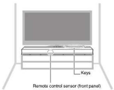
About the TV remote repeater
The unit receives signals from the TV's remote control via the remote control sensor located on the front panel. It then transmits these signals from the TV remote repeater located on the rear panel. See page 10 in the Owner's Manual for more information.

Mounting the unit on a wall
Mount the unit on the wall so that the keys face upwards. Follow the instructions on page 11 in the Owner's Manual when mounting the unit on a wall.
Caution
- When mounting the unit on a wall, all installation work must be performed by a qualified contractor or dealer. The customer must never attempt to perform this installation work. Improper or inadequate installation could cause the unit to fall, resulting in personal injury.
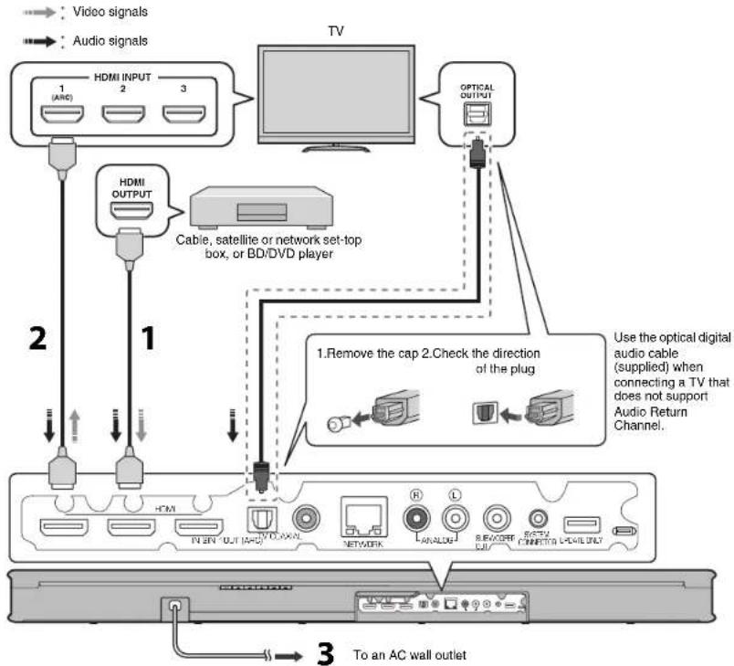
Connecting the unit to a TV and set-top box
For the cable connection, follow the procedure below.
flowchart
graph TD
    A["Video signals"] --> B["1 (ARC)"]
    C["Audio signals"] --> D["2"]
    B --> E["HDMI INPUT 1"]
    D --> F["HDMI OUTPUT 1"]
    E --> G["Cable, satellite or network set-top box, or BD/DVD player"]
    F --> H["Use the optical digital audio cable (supplied) when connecting a TV that does not support Audio Return Channel."]
    G --> I["1. Remove the cap 2. Check the direction of the plug"]
    H --> J["3. To an AC wall outlet"]
    I --> K["Network"]
    J --> L["Analog"]
    K --> M["8x80Hz C/I"]
    L --> N["8x80Hz C/I"]
    M --> O["6x80Hz C/I"]
    N --> P["6x80Hz C/I"]
See pages 13 to 14 in the Owner's Manual when connecting other playback devices such as a game console.
1 HDMI cable (optional)
The digital audio/video signals from the set-top box or BD/DVD player are input to this unit.
NOTE
• This unit supports HDCP version 2.2, a copy protection technology.
2 HDMI cable (optional)
Digital video from the set-top box or BD/DVD player is displayed on the TV.
NOTE
- Connect the unit to the HDMI input jack (one compatible with HDCP 2.2) on an HDCP 2.2-compliant TV to enjoy playback of 4K video.
3 Power cable
Plug the unit's power cable into an AC wall outlet after all the connections are complete.
HINT
Audio Return Channel (ARC) supported TV
- Connect an HDMI cable to the audio return channel supported jack (the jack with "ARC" indicated) on TV.
- Enable the HDMI control function of this unit to activate the Audio Return Channel (ARC). See page 46 in the Owner's Manual.
What is Audio Return Channel (ARC)?
- In order for the unit to play audio from a TV, the TV must usually be connected to the unit via an audio cable as well as an HDMI cable. If, however, the TV supports Audio Return Channel (ARC), TV audio signals can be input to the unit via the HDMI cable that outputs video signals from the unit to the TV.
For a wired network connection, connect one end of the network cable to the NETWORK jack on the rear panel of the unit and the other end to a router (p. 26 in the Owner's Manual).
Turning on the unit
This section explains initial setup of the unit, performed when it is turned on for the first time after purchase.
Connecting the subwoofer wirelessly
1 Plug the subwoofer's power cable into an AC wall outlet.
2 Press the ⏻ key to turn on the unit.
When the center unit is turned on, the center unit and subwoofer are automatically connected via wireless connection. Once the connection has been successfully established, the STATUS indicator on the subwoofer glows as shown in the illustration below, and the unit is ready for play back.
Screen displayed on a TV when the unit is turned on
When the unit is turned on for the first time after purchase, the screen shown below will be displayed on the TV and the 📤 indicator will be flashing.
HINT
- When the screen is not displayed, use the input button on the TV's remote control to switch input so that video input from this unit is displayed. When this unit is connected to the TV as shown on page 13, select "HDMI 1".
- The language used for menu display (OSD Language) can be selected from the screen shown above. Use the ◀/▶ key to select the language, and follow the on-screen instructions. The OSD language can also be changed from the setup menu at any time. Press and hold the SETUP key
until the "OSD Language" menu is displayed on the TV, and use the ▲/▼ key to select the language. Press the SETUP key to exit the setup menu.
![Share Wi-Fi Settings You can share the wireless (RI-FI) settings of the network with Sound Box using a device with H57 or later. [ORER] Start [RETURN] Cancel ◀▶ 000 Language](/content/2026/04/716150/images/93ff065dcff4d9ccfb87dfe565fad125870d4213e19db2dcc52620ab102bfb47.jpg)
Follow the on-screen instructions to use an iOS device (iPhone, etc.) to connect the unit to a wireless network (p. 41 in the Owner's Manual).
Connecting the unit to a wireless network is simpler when the MusicCast CONTROLLER app* installed on your mobile device is used. Press the RETURN key to cancel this screen, and then refer to "Connecting with the MusicCast CONTROLLER app (registering the unit as a MusicCast-enabled device)" on page 20.
* MusicCast CONTROLLER is a free app for mobile devices.
HINT
- This screen will not be displayed if the unit is connected to a router via its NETWORK jack (wired connection).
NOTE
- If the STATUS indicator does not glow properly the first time the unit is turned on, pair the center unit and subwoofer manually. See "Pairing the center unit and subwoofer" (p. 62 in the Owner's Manual).
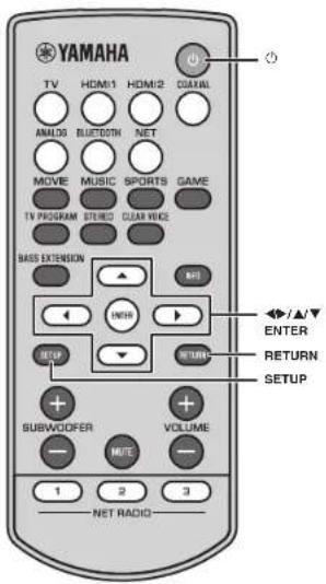
Operations
Remote control signal transmitter
Transmits infrared signals.
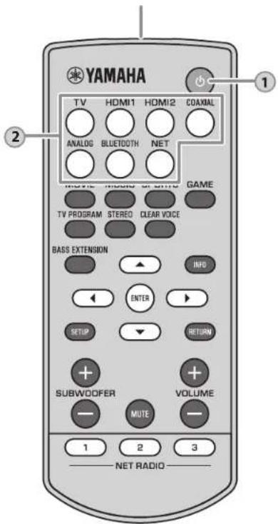
1
(power) key
Turns on or off the unit.
Turned on
Turned off (when the HDMI control function (p. 46 In the Owner's Manual) or network standby function (p. 49 In the Owner's Manual) is enabled)

Turned off

2
Input keys
Select an input source to be played back.
TV TV audio or sound from a device connected to the unit's TV input jack
HDMI 1, HDMI 2 ....Sound from a device connected to the HDMI IN 1 or HDMI IN 2 jack
COAXIAL ....Sound from a device connected to the COAXIAL input jack
ANALOG.....Sound from a device connected to the ANALOG input jacks
BLUETOOTH ....Sound from a Bluetooth connected device
NET ......Audio acquired via a network The last audio source listened to is selected when the NET key is pressed.
The indicator for the selected input source glows. (Example: when TV is selected)
HINT
- To play sound from the device connected to the TV or to watch video from the device, set the TV's input source to the playback device.
- For playback from a Bluetooth device, refer to page 24 in the Owner's Manual. For audio playback via a network, refer to pages 39 to 42 in the Owner's Manual.
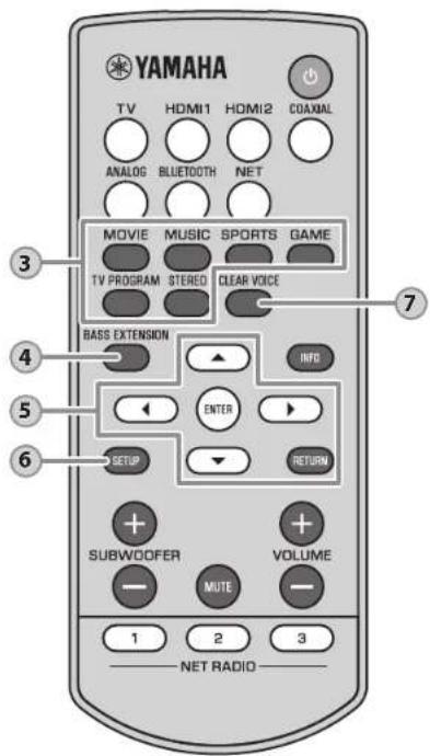
3
Surround program keys and STEREO key
Select surround playback using the MOVIE, MUSIC, SPORTS, GAME or TV PROGRAM key, or select stereo (2 channels) playback using STEREO key. When a surround program (MOVIE, MUSIC, SPORTS, GAME, or TV PROGRAM) is selected, you can enjoy a realistic sound effect using Yamaha's exclusive AIR SURROUND XTREME.
MOVIE, MUSIC, SPORTS, GAME, or TV PROGRAM
Glows (surround playback)
STEREO.... Off stereo playback) HINT
- Dolby Pro Logic II is used when 2-channel stereo signal is played with a surround program other than MUSIC.
4
BASS EXTENSION key
Enable/disable the bass extension function. When this function is enabled, you can enjoy a powerful bass sound with the Yamaha original bass boost technology "Advanced Bass Extension Processing."

Enabled: Flashes three times and goes out Disabled: Flashes once and goes out
5
▲/▼/◄/► keys, ENTER key, RETURN key
Use to configure the setup menu.
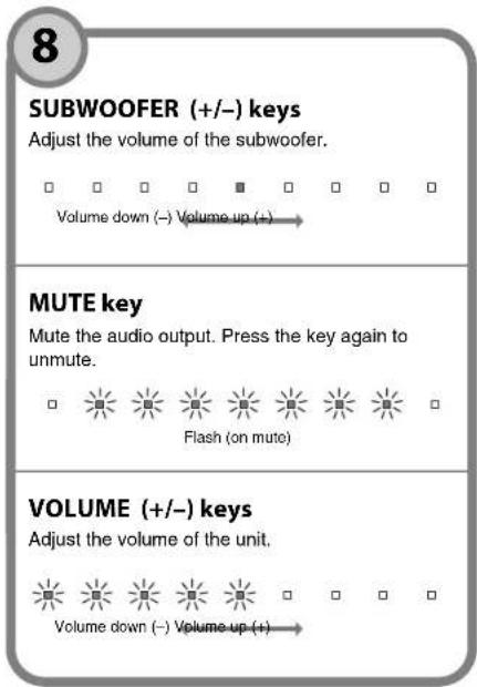
6
SETUP key
Display the setup menu on the TV.
7
CLEAR VOICE key
Enable/disable the clear voice function. When this function is enabled, human voices such as lines in movies and TV shows, or news and sport commentary, are played clearly.

Enabled: Flashes three times and goes out Disabled: Flashes once and goes out
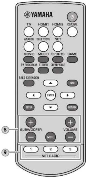
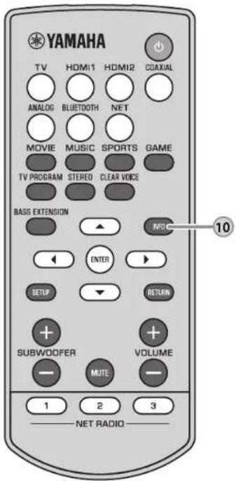
10
INFO key
While the INFO key is held down, status, including the type of audio signal being input and whether the clear voice function is enabled or disabled, can be confirmed by the glowing of indicators.
Type of audio signal being input
TV audio input signal with the ARC function activated
DTS digital surround, DTS 96/24, DTS Express, DTS-HD High Resolution, or DTS-HD Master Audio

Green
Dolby Digital, Dolby Digital Plus, or Dolby TrueHD

Green
Dolby Pro Logic II is used (when 2-channel stereo signal is played with a surround program other than MUSIC)

Green
Unit functions and positioning
The bass extension function is enabled

The clear voice function is enabled

When positioned on top of something, such as a TV stand

When mounted on a wall

HINT
- The unit is able to play the following types of audio signal. The indicators do not glow when analog or PCM audio signal is input.
- Analog signal
- Dolby TrueHD
- PCM (2 channels, multi-channels) - DTS digital surround
- Dolby Digital - DTS 96/24
- Dolby Digital Plus
Networks
Network functions and the MusicCast CONTROLLER app
A network connection allows you to listen to Internet radio stations or music streaming services, and to use AirPlay to play music files, or to play music files stored on your computer (media server) via this unit.
Most playback requires the "MusicCast CONTROLLER" app for mobile devices. Install and use the MusicCast CONTROLLER app on your mobile device to play music files.
Proceed from network connection to playback in the following sequence.
1 Choose a wireless network connection (p. 19) or a wired network connection (p. 26 in the Owner's Manual).
↓
② Use the MusicCast CONTROLLER app to connect the unit to a network, and register the unit as a MusicCast-enabled device (p. 20).
↓
3 Use the MusicCast CONTROLLER app to play music over a network* (p. 39 to 42 in the Owner's Manual).
AirPlay can be used to play music files without using the MusicCast CONTROLLER app.
NOTE
- To use network function, the unit, your PC and mobile device must be connected to the same router. Make sure whether the network parameters (such as the IP address) are properly assigned to the unit in "Information" in the setup menu (p. 47 in the Owner's Manual).
- When using a multiple SSID router, access to the unit might be restricted depending on the SSID to connect. Connect the unit and mobile device to the same SSID.
- Some security software installed on your computer, or network device settings (such as a firewall), may block the unit's access to your computer or Internet radio stations. Should this occur, change security software and/or network device settings.
- A network connection cannot be established if the MAC address filter on your router is enabled. Check your router's settings.
- To configure your router's subnet mask manually, apply the same subnet used by this unit to all devices.
- Use of a broadband connection is recommended when using Internet services.
HINT
- If your router supports DHCP, network settings for the unit need not be configured. Network parameters (such as the IP address) will be assigned automatically. If your router does not support DHCP, or if you prefer to configure network parameters manually, you must configure network settings yourself (p. 48 in the Owner's Manual).
Connecting to a network
This section explains wireless network connection. For information regarding wired network connection, see the Owner's Manual.
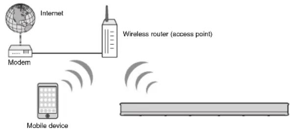
Wireless network connections
Connect the unit to a wireless router (access point) to use a network.
Refer to the following for instructions on connecting to a wireless router (access point).
• Using the MusicCast CONTROLLER app (p. 20)
- Using connection methods other than the MusicCast CONTROLLER app (p. 30 to 36 in the Owner's Manual)
flowchart
graph LR
    A["Internet"] --> B["Modem"]
    B --> C["Wireless router (access point)"]
    D["Mobile device"] -->|Signal| E["Antenna"]
    E -->|Signal| F["Antenna"]
The indicator on the unit glows when the unit is connected to a wireless network.

NOTE
- You cannot use the wireless network connection simultaneously with the wired network connection or Wireless Direct (p. 37 in the Owner's Manual).
- If the unit and the wireless router (access point) are too far apart, the unit may not connect to a wireless router (access point). In such case, place them close to each other.
HINT
- If the unit will not be connected to a wireless router (access point), Wireless Direct (p. 37 in the Owner's Manual) can be used to connect the unit directly to a mobile device to control the unit using the MusicCast CONTROLLER app installed on that mobile device.
NETWORKS ▶ Network functions and the MusicCast CONTROLLER app
Connecting with the MusicCast CONTROLLER app (registering the unit as a MusicCast-enabled device)
Install the MusicCast CONTROLLER app on your mobile device to connect the unit to a network and register it as a MusicCast-enabled device.
HINT
- Confirm that your mobile device is connected to your home router before beginning.
- This section uses MusicCast CONTROLLER app screens displayed in English on an iPhone as examples.
- MusicCast CONTROLLER app screens and menu labels are subject to change without prior notice.
1 Install the MusicCast CONTROLLER app on your mobile device, and open the app.
Search for "MusicCast CONTROLLER" on the App Store or Google Play.
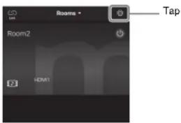
2 Tap "Setup".

HINT
- If a different MusicCast-enabled device is already registered with the MusicCast CONTROLLER app, tap (Setup) in the room selection screen, and then select "Add New Device" to add the unit to the app.
3 Turn on the unit, and then tap "Next".
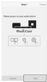
4 Hold down the CONNECT key until the 🔺 indicator on the unit starts flashing.
5 Follow the on-screen instructions to configure network settings.
HINT
- When a screen like that below is displayed, follow the on-screen instructions to configure network settings.
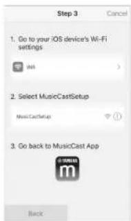
- Use the Home button on your mobile device to return to the Home screen.
- Select "Wi-Fi" from "Settings".
- Select "MusicCastSetup" from "CHOOSE A NETWORK...".
- Use the Home button to return to the MusicCast CONTROLLER app.
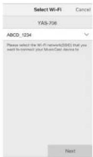
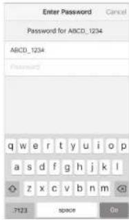
- When a screen like that at left below is displayed, select the network to which the unit will be connected and enter the router's password (encryption key).
The router's password (encryption key) is often noted on the router itself. Refer to documentation supplied with the router for details.


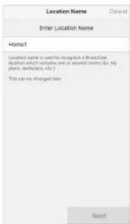
6 To register the unit as a MusicCast-enabled device, configure the following items.
- Location name ("home", "John's house", etc.)
- Name and photo of the room where the unit is installed
The location name, and the name and photo of the room where the unit is installed can be changed later.
Network connection with the MusicCast CONTROLLER app is now complete, and the unit has been registered as a MusicCast-enabled device.
The unit is equipped with a number of other functions not described in this booklet. See the Owner's Manual for details.
PRÉCAUTIONS CONCERNANT LA SÉCURITÉ

ATTENTION
RISQUE DE CHOC ÉLECTRIQUE NE PAS OUVRIR

ATTENTION: POUR RÉDUIRE LES RISQUES D'INCENDIE ET DE DÉCHARGE ELECTRIQUE, NE PAS RETIRER LE COUVERCLE (OU LE PANNEAU ARRIÈRE). NE CONTIENT AUCUNE PIÈCE INTERNE RÉPARABLE PAR L'UTILISATEUR. POUR L'ENTRETIEN, S'ADRESSER À UN PERSONNEL QUALIFIÉ.
natural_image
Simple line drawing of a rectangular object with a horizontal line and a separate vertical rectangle (no text or symbols)⑨Prise SUBWOOFER OUT
Touche ⏻ (alimentation)
MOVIE, MUSIC, SPORTS, GAME, ou TV PROGRAM Allumé (lecture surround)
Touche BASS EXTENSION
ASTUCE


Funcionamiento
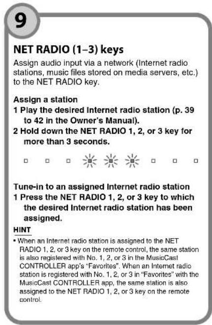
Botones NET RADIO (1–3)
DTS Digital Surround, DTS 96/24, DTS Express, DTS-HD High Resolution o DTS-HD Master Audio
Verde
Dolby Digital, Dolby Digital Plus o Dolby TrueHD
Verde

Manual Development Group
© 2016 Yamaha Corporation
Published 06/2016 KS-B0
Printed in Indonesia
ZW71760