TST-2 - Garage remote CHAMBERLAIN - Free user manual and instructions
Find the device manual for free TST-2 CHAMBERLAIN in PDF.

User questions about TST-2 CHAMBERLAIN
0 question about this device. Answer the ones you know or ask your own.
Ask a new question about this device
Download the instructions for your Garage remote in PDF format for free! Find your manual TST-2 - CHAMBERLAIN and take your electronic device back in hand. On this page are published all the documents necessary for the use of your device. TST-2 by CHAMBERLAIN.
USER MANUAL TST-2 CHAMBERLAIN
Operational description
Operational description
Operational description
This manual is dedicated to those persons projecting and planning the TST WS-B control system of Chamberlain GmbH. Initiation should only be done by a skilled electronics engineer who is acquainted with the safety standards of electric driving- and automation systems. A description of the control system resp. relevant excerpts hereof have to be put at the user's disposal when passing on the control system.
- The data indicated in this manual may be altered without previous notice.
- With the edition of this manual, all previous editions become void.
- Composition of the information given in this manual has been done to the best of our knowledge. Chamberlain GmbH does not guarantee the correctness of the details given in these instructions and may not be held liable for damages ensuing from incorrect installation.
Description of the products, their application, features and performance data are no assured characteristics and are subject to technical alterations.
- Since, despite of all our efforts, errors may not be completely avoided, we are always grateful for your useful tips.
- The installation instructions given in this manual are based on advantageous boundary conditions. Chamberlain GmbH does not give any guarantee promise for perfect function of the control system in a cross surrounding.
Warranty claims towards Chamberlain GmbH restricted to the customer and may not be transferred. The warranty promise comprises only those products delivered by Chamberlain GmbH. We are non-liable for the whole system.
Instructions to Software
- Chamberlain GmbH reserves the right to alter or extend its software without prior notice, as long as functionality remains untouched resp. is adjustable. Before applying individual software, the correctness of the software has to be acknowledged and a written declaration of consent regarding these alterations has to be obtained from by the customer
Our guarantee comprises repair in our workshop. The software versions resulting hereof have to be installed by the customer. Guarantee for software is restricted to reproducible errors. - Chamberlain GmbH has no obligation to make alterations to products already delivered.
- The customer or third parties are not permitted to change the program. Chamberlain GmbH may not be held liable for defects ensuing from these changes.
CONTENTS
1 GENERAL INFORMATION ON THE CONTROL DEVICE 3
2 SAFETY INSTRUCTIONS 4
3 MOUNTING OF THE CONTROL DEVICE 5
4 ELECTRICAL CONNECTION. 5
5 INPUTS / OUTPUTS 6
5.1 INPUTS 6
5.2 OUTPUTS 6
1 General information on the control device
- Main application: industrial doors with electric drive (up to 2.2 kW, 400 VAC, AC-3)
- mounted in the special door control housing TST GA with transparent cover for diagnostic.
- automatic or deadman opening and closing travel (closing travel in connection with closing edge security device)
- automatic closure after an adjustable hold-open time (1 ...320 s)
-
integrated safety edge evaluation (monitoring of door closing travel) with plug-in clamps for:
-
resistance monitoring (8.2/1.2 kΩ), N.C. or N.O. principle, selectively tested or redundant evaluation ("electrical" or "pneumatic" security strip)
-
evaluation of an optical safety edge (type: "Fraba-OSE")
-
door cycle counter (in steps of 10 via LEDs)
- selectable reverse time (0.25s / 0.05s)
run time control 60s
2 Safety instructions
During commissioning and operation of the control device the following important safety instructions and the subsequent mounting and connection instructions must be observed:
- All installation, commissioning and maintenance work must be exclusively carried out by qualified specialist personnel. In particular, the following regulations must be observed (without this list being exhaustive): VDE regulations (VDE 0100, VDE 0105, VDE 0113, VDE 0160, VDE 0700), fire prevention regulations, accident prevention regulations and the relevant regulations for industrial doors (ZH1/494, prEN12453, prEN12978)
- The control device must only be opened when power is switched off at all poles.
- The control device must not be operated in the open condition.
- The control device may be operated with the CEE plug disassembled only if the mains power supply can be isolated from the control device at all poles by means of an appropriate switch.
- The control device must not be operated with a defective membrane keypad. Damaged keypads must be replaced. The keypad is basically provided only for finger operation. It should not be operated with sharp objects.
- Before the control device power supply is switched on for the first time, it must be ensured that all insert cards are correctly placed in the insertion spaces provided for them.
- When the door is moving in deadman operation it is to be ensured that the door region can be seen by the operator since, in this type of operation, security devices such as the security strip and light barriers can be bypassed.
- The manual operation of the contactors is prohibited. The guarantee becomes void if the protective foil is destroyed.
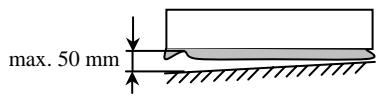
- According to prEN12453 the pre-end switch of the security strips may be positioned at a maximum of 50mm above the lower end position. The details given in the chapter
- Clamping and connection plan for the security strip" are to be strictly followed.
- Check the setting of all DIP switches and operation of the security devices.
Failure to comply with safety instructions can result in a risk to health or to the control device being damaged.
These safety instructions are not intended to be exhaustive. Please discuss any queries with your supplier.
The manufacturer has carefully checked the device hardware and software and the product documentation but cannot provide any guarantee against errors.
The serial number is applied on a separate sticker to the printed circuit board and to the control housing. For motor dates (nominal load and torque, etc) construction year and additional information, please read the technical information of motor and door.
TSTWS
Control Device
3N~400V / ~230V
50...60Hz / 2500W
IP54 (IP65) / -10...+50°C
FEIG
ELECTRONIC

3 Mounting of the control device
- Before mounting, the control device is to be checked for damage which may have occurred during transportation or for some other reason. Damage inside the control device can lead, under certain circumstances, to considerable subsequent damage to the control device and even pose a health risk for the user.
During mounting of the control device, the installation is to be made voltage-free. - The control device is provided for mounting directly on a wall. It is attached by means of the wall-mounting device located on the underside. The control device must always be mounted in such a way that the cable lead-ins always point downwards. It is to be ensured that no transfer of mechanical vibrations through the door to the control device is possible (eg mounting on a masonry wall).
- Mounting must only be to flat surfaces. The housing must be mounted in a distortion-free manner.
- The mounting site is to be selected such that the control device is not subjected to direct sunlight and so that the weather can not otherwise have any direct effect on the control device.
- The door to be operated must be visible from the control device in order to permit deadman operation which is possible from the membrane keypad.
- The touching of electronic parts, in particular, the parts of the processor circuit is to be avoided. Electronic components can be damaged or destroyed by electrostatic discharge. It is not possible to avoid touching of the electronic components, an earthed location must be contacted shortly before (eg an earthed door frame).
4 Electrical connection
- Connection, checking and maintenance work on the opened control device must be carried out only in the voltage-free state. Particular attention should be paid to the points set out in the Safety instructions section.
- The control device is only designed for a nominal voltage of 230/400V ± 10% 50/60Hz . Neutral and protective earth conductors must be connected. In operation at 230V the clamping sites L3 (contactor), N and PE must be used.
- The supply inlet is to be secured at the installation site with 16A actuation feature K. The drives are to be fitted with additional over-load protection (eg thermoplate).
- If the voltage free contacts of the relay outputs or other terminal clamps are connected to a external supply, that means they have a dangerous voltage which can be active after switch off of the control ore disconnecting of the supply plug, a warning sticker has to be mounted visible on the control box: "NOTE! Before working on terminal clamps, all power circuits must be switched off."
- The control voltage 24V_DC (direct voltage) for external devices and the device's own external control circuits are to be secured by a self-resetting semi-conductor protection device. Resetting takes place after the overload or short-circuit has been overcome and after a short cooling phase.
- All control voltage inputs are dc-insulated from the supply by a basic insulation. They are arranged irregularly for 24V_DC , wherein the inputs can be provided with potential-free contacts or limited with 24V active outputs.
- According to EN60335 all components connected to the control device must have also basic insulation for a operation voltage up to 230V
- Extremely high electrostatic charges can occur in doors. Discharging takes place via the closest point which has a protective earth conductor covering. If, by reason of incorrect cabling, discharge onto the control inputs which are under the earth covering is made possible, the control device may be damaged. The connections of the security strip are particularly at risk. As a countermeasure, a discharge device on the door leaf is to be recommended.
- The connection for the cables introduced into the control device is to be kept as short as possible and to lead as directly as possible to the connection clamp.
Maximum connection cross-section of the used terminal clamps:
| screw clamps | plug clamps | |
| single wire (rigid) | 2,5mm² | 1,5mm² |
| thin wired /with/without vein end sleeve | 1,5mm² | 1,0mm² |
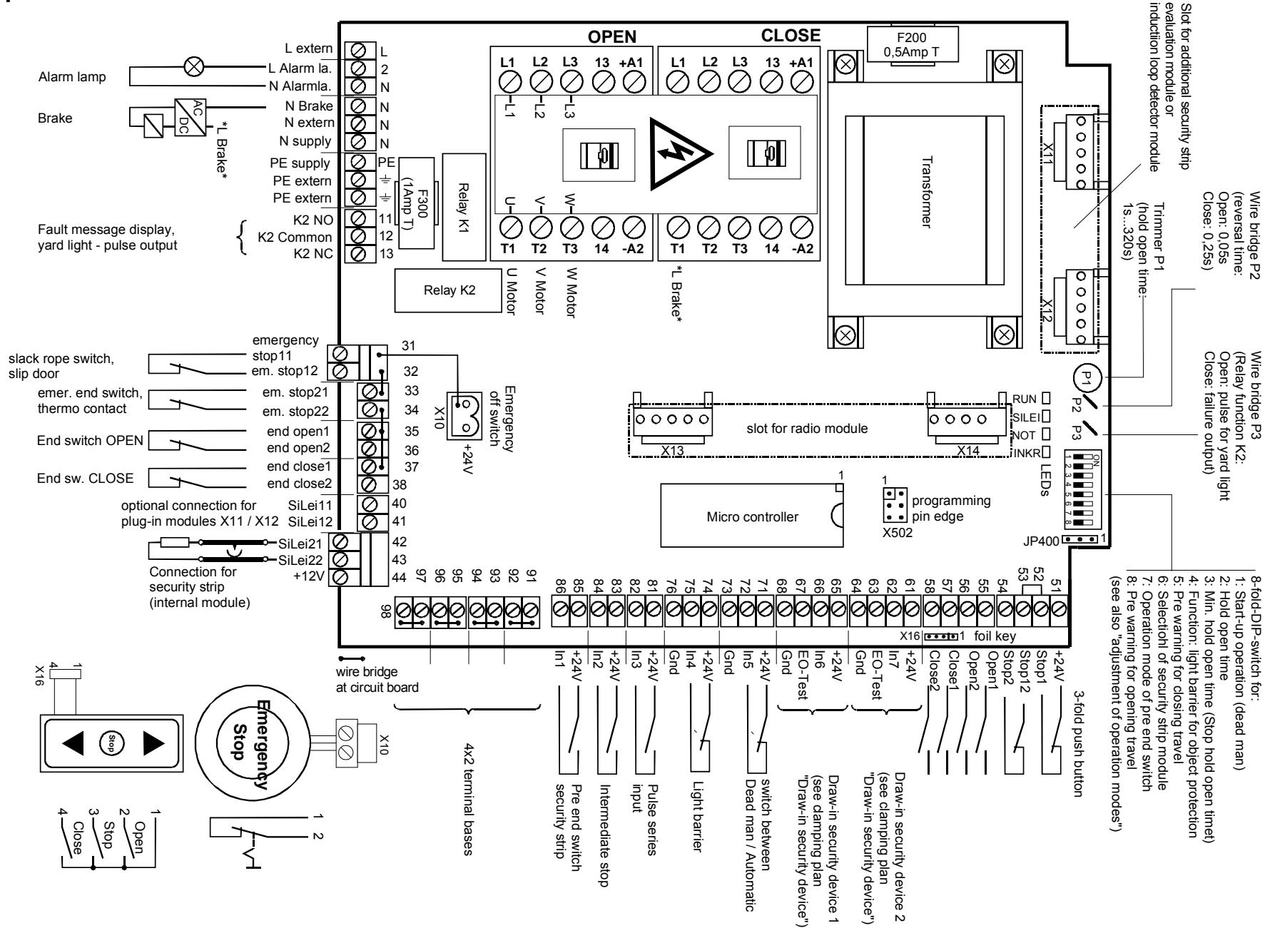
- Connection arrangement see separate drawings in appendix.
PLEASE NOTE:
Under no circumstances leave behind mounting or wiring remains in the control housing. Electrically conductive remains can lead to severe damage on the printed circuit board.
Tighten all screws on the contactor, even those assumed not to be used.
5 Inputs / Outputs
5.1 Inputs
| Input | Clamp | Function(DIP...) see chapter "Setting of types of operation" | Circuit feature to be connected |
| IN1 | 85-86 | Pre-end switch security strip (DIP 6, 7) | Closing device |
| IN2 | 83-84 | End switch - intermediate holding operates upon all open commands (with membrane keypad OPEN can travel from intermediate holding position into upper end position) | Closing device |
| IN3 | 81-82 | Pulse series - Input: OPEN->STOP->CLOSE->STOP(no automatic closing travel after expiring of hold-open time) | Closing device |
| IN4 | 74-75 | Object protection - light barrier \(1^{1}\): (DIP 2, 3, 4) when actuated: automatic opening travel, deadman closing travel permitted. | Opening device\( ^{2} \) |
| IN5 | 71-72 | Switch over deadman/automatic when actuating (interrupting) deadman operation each new actuation firstly causes a stop | Opening device\( ^{2} \) |
| IN6 | 65-66 | Draw-in security device 1: during actuation: locking the opening travel, deadman closing travel | Opening device with testing\( ^{2} \)(see enclosure D) |
| IN7 | 61-62 | Draw-in security device 2: see draw-in security device 1 | Opening device with testing\( ^{2} \) |
| Emergen-cy stop 1 | 31-32 | Emergency stop chain \(1^{1}\): Slack rope switch, slip door (short-term actuation at beginning of closing travel from upper end position effects an automatic return approach ) | Opening device |
| Emergen-cy stop 2 | 33-34 | Emergency stop chain \(2^{1}\): Emergency end switch, thermoplate,... | Opening device |
| Upper end | 35-36 | Upper end switch\( ^{1} \) | Opening device |
| Lower end | 37-38 | Lower end switch\( ^{1} \) | Opening device |
| Stop ext 1 | 51-52 | Three-function push button 1\( STOP^{1}\): no travel possibleOPEN: automatic opening travel, no deadman function (DIP 2)CLOSE: automatic closing travel, no deadman function | Opening device\( ^{2} \)Closing deviceClosing device |
| Open ext 1 | 55 | CLOSE: automatic closing travel, no deadman function | |
| Close ext 1 | 57 | ||
| Stop ext 2 | 53-54 | Three-function push button 2\( STOP^{1}\): no travel possibleOPEN: automatic opening travel, no deadman function (DIP 2)CLOSE: automatic closing travel, no deadman function | Opening device\( ^{2} \)Closing deviceClosing device |
| Open ext 2 | 56 | General: closing travel still possible in deadman operation only | |
| Close ext 2 | 58 | ||
| Sec. strip 21/22 | 42-44 | Security strip (via integrated evaluator) during actuation or fault: during closing travel: reversing (stop->opening travel) | |
| Radio mod chan. 1+2 | - | channel 1: OPEN->STOP->CLOSE->STOPchannel 2: OPEN->EO->CLOSE->OPEN | - |
| Sec. strip 11/12 | 40-41 | Additional security strip (via plug-in module) during actuation or fault: during closing travel: reversing: STOP->closing for 0,5 sec.->STOPgeneral: closing travel still possible in deadman operation only | - |
| Det 1/2 | Connec. directly on detector | 2-channel induction loop detector (via plug-in module) while actuation effects: general opening while closing->reversal | - |
1: if this input is not used, an appropriate wire bridge must be inserted
2: bridged ex works
5.2 Outputs
| Output | Clamp | Function | Switching feature |
| Relay K1 | 2-N | Warning light, flashes during travel and between the end positions. Exception: Emergency stop and deadman operation (see also DIP 5) | Closing device, 230 V switching |
| Relay K2 | 11-12-13 | Fault indication output/ yard light function: *see wirebridge P3) | Change-over contact, potential-free |
| OPEN- contactor | 13-14 | Indication of opening travel active | Closing device, potential-free |
| CLOSE- contactor | 13-14 | Indication of closing travel active | Closing device, potential-free |
6 Commissioning
The following introduction serves as directions for checking and setting door installations with mechanical end switches and contains some important observations which are to be considered. Familiarisation with the preceding chapter is a requirement.
NB: When changing security strip systems, switch off the control device and after connection of the new system, set to setting operation (DIP1=On). For use of pneumatic strip (pressure switch) DIP-switch 6 has to be in the testing mode (DIP6=ON)
- Check the electrical connections according to the connection configuration plan, the door mechanism and the desired installation configuration including the associated DIP switches and plug-in modules so that no mechanical or electrical risk can arise from any of the components.
- Check the power connection at site for right rotary field of the 3 phases
- Bring the door into the middle position with the control device switched off and set the mechanical end switches in such a way that no switch is actuated.
- Switch DIP switch S1 to "OFF". The control device works in dead man operation after being switched on, ie. the drive runs only as long as the OPEN or CLOSE button of the membrane keypad is actuated. NB: The door moves in this type of operation without consideration of the security devices (light barriers, security strip, draw-in security device)
- Plug in mains power plug or switch on the power supply.
- Use the CLOSE button to move the door close to the closed position. NB: with doors of unknown slow-down travel, leave sufficient spacing from the end position.
- If the door turns in the wrong direction: incorrect motor rotary field, shut off the power and exchange two motor connections.
- Set the lower end switch such that it is just actuated. Then adjust the end switches more precisely as required, by further movements into this end position.
NB: End switches must not be passed over in the end positions.
- Set lower security end switch. Observe the setting requirements of the drive manufacturer.
- Use OPEN button to move the door close to the open position.
- Set upper end switch such that it is just actuated. Then adjust the end switches more precisely as required, by further movements into this end position. NB: End switches must not be passed over in the end positions.
- Set upper security end switch. Observe the setting requirements of the drive manufacturer.
- Intermediate holding (if required): Move door into the desired intermediate holding position.
- Set intermediate holding switch such that it is just actuated (considered from opening travel direction)
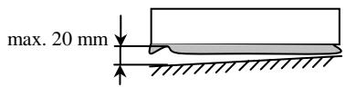
- Adjustment of pre-end switch:
The pre-end switch is used for a switch -off of the reversal function when security strip is actuated. It must be adjusted relating to the door type shown in the figure below. The gap between the actuation point of the security strip and the floor should max. 50 or 20mm .
DIP 7:OFF
Switch off reversal
DIP 7: ON
Ignore security strip actuation
- Set pre-end switch in such a way that during closing travel it is just actuated at this position.
- Check and if necessary correct the end switch positions by dead man opening and closing travel.
- Switch off control device and switch DIP switch S1 to "ON". The control device is in automatic operation when switched on again.
- Check operation of all security devices such as closing edge security device, light barriers, emergency stop etc.
7 Operation
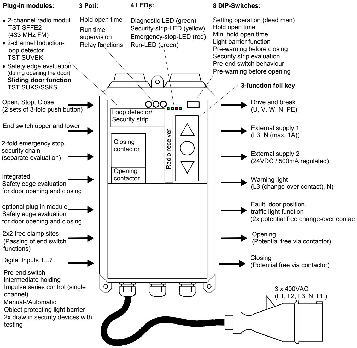
The main operating elements of the TST-WS-A door control device are in the top right corner of the plate when viewed straight on.
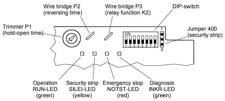
Fig. 8.1: Operating elements of the TST WS-B
Note :
Adjustments of the control elements can only be made by instructed personnel
7.1 Wire/plug-in bridges
| Bridge/Jumper | Function | Reaction |
| Bridge P2 | Reversing time | Dwell time before changing travel direction (contactor switch over) reversal of security strip |
| closed | 0.25s | - |
| broken | 0.05s | - |
| Bridge P3 | Relay function K2 | |
| closed | Fault output | "Fault indicator relay" (fault exists if after 5 minutes of permanent holding of stop, open, emergency stop, light barrier or draw-in security device, no automatic operation is possible.Exception: Open/stop commands, light barriers or security strip are in upper end position/intermediate holding is not yet engaged. |
| broken | Yard light | "Yard light actuating pulse" (1s pulse before each commencement of travel to actuate an automatic staircase device) |
| Jumper | Security strip | Terminating resistor of the security strip |
| JP400 | 1.2kΩ | - |
| 8.2kΩ | - |
7.2 Setting of the hold-open time (trimmer P1)
It effects the automatic closing travel of the door after expiry of this time from the upper end position or the intermediate holding position.
- The hold-open time is activated by the switching of the DIP2 switch into the ON position.
It can lie within the range of 1s to approx. 320s. The setting range is illustrated in the bottom of the Figure.
- An active emergency stop input or a stop command deactivates the hold-open time.
- The hold-open time only runs out after release of all open commands and security devices.
- The hold-open time is deactivated with three closing travel attempts take place one after the other, wherein the security strip has been actuated.
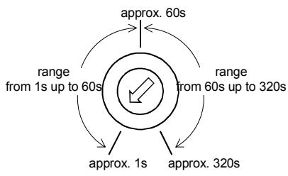
Fig. 8.2: setting range of trimmers P1
7.3 Display door cycle counter
The door cycle counter counts the door movements from one end position into the other end position. It therefore provides information about the entire use of the door. This counter reading can be illustrated by the following button combination on the LEDs:
- Press emergency switch-off mushroom-type button
- Press OPEN membrane button and keep pressed
- Press CLOSE membrane button
The buttons can now be released
As a starting symbol of the output all 4 LEDs light up for approx. 0.5s. The door cycle counter is now displayed according to the diagram below. The display begins with the highest-value LED.
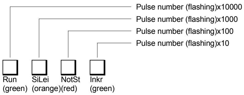
Fig. 8.3: Output of the counter readings on the LEDs
Example:
A door cycle counter reading/maintenance cycle counter reading of 63856 is displayed in the following sequence:
- 6x flashes of the Run-LED (6 × 10000 = 60000)
3x flashes of the Sec. Strip-LED(3x 1000 = 3000)
8x flashes of the Emerg. stop-LED (8x 100 = 800)
5x flashes of the Incr.-LED (5x 10 = 50)
The last position is not dipslayed.
->This display mode can be exited by pulling the emergency switch-off button.
7.4 Carrying out reset function
The reset function serves to restart the control device without shutting off the power supply. By means of this function errors can be cancelled. The counter readings and functions set thus remain unaltered.
Press foil key STOP, OPEN and CLOSE together -> control device restarts
7.5 Setting of types of operation (DIP switches)
The types of operation are set by DIP switches attached to the plate. The following table serves to describe the possible functions.
| DIP 1Automatic Activate setting operation | |||
| OFF | Dead man | Only dead man function for opening and closing travel (without consideration of secu. strip, object protection light barrier and ext. transmitters of open/close commands) | |
| ON | Automatic | Automatic opening travel, automatic closing travel when security strip presentAutomatic opening travel, dead man closing travel when security strip is actuated/faulty | |
| DIP 2Hold-open timeAutomatic closing device, forced closing | |||
| OFF | inactive | no automatic closing device active | |
| ON | active | After reaching the upper end position (or intermediate holding) and after release of all opening commands and security provisions the time set by the trimmer P1 begins. After the hold-open time has expired, the door closes automatically. The hold-open time is interrupted by active emergency stop or stop command. When the object protection light barrier, open command or security strip is active, the hold-open time is kept at a maximum. | |
| DIP 3Min. hold-open timeInterruption of the hold-open timeFunction only active when hold-open time active (DIP2:on) | |||
| OFF | inactive | No minimum hold-open time active | |
| ON | active | • 2s after release of object protection light barrier, closing travel takes place• When pre-warning active (see DIP 5), the pre-warning time runs directly from 3s. | |
| DIP 4Light barrier functionOperating method of object protection light barrier | |||
| OFF | Closing travel | • During closing travel reversing• During opening travel no function | |
| ON | Opening and closing travel | • During closing travel reversing• During opening travel as stop command. As long as actuation is set, only deadman travel is possible. After release automatic opening travel (2s delay) takes place as far as the corresponding previously requested end position (intermediate holding, upper end position). A hold-open time which may have been set begins to run. | |
| DIP 5Pre-warning | |||
| OFF | inactive | Warning light (relay K1) flashes only during opening and closing travel | |
| ON | 3s | Warning lamp flashes 3s before each movement, commencement of travel is delayed by 3s | |
| DIP 6Security stripSelection of the security principle according to prEN 12453(see also clamping plans "security strip") | |||
| OFF | Redund-ancy | During the closing travel until activation of the lower pre-end switch or of the end switch both independent signals of the security strip evaluation must always show the same signals. If there is a signal change on one channel, the second channel must follow at the latest 100ms later. | |
| ON | Testing | NB: must be activated in the case of pneumatic strips after activation of the lower pre-end switch or when the lower end position switch is reached during/after closing travel, actuation of the security strip is expected within 3s. | |
| DIP 7Pre-end switchBehaviour of the door before and after activation of the pre-end switch | |||
| OFF | Reverse switch off | • Before activation: Actuation of the security strip effects immediate stop with subsequent reopening travel• After activation: Actuation of the security strip effects immediate stop | |
| ON | Ignoreactuation | • Before activation: Actuation of the security strip effects immediate stop with subsequent reopening travel• After activation: Actuation of security strip is ignored NB: during actuation there is no display of the sec. strip LED | |
| DIP 8pre alarmBehaviour of the alarm lamp before opening travel | |||
| OFF | inactive | • alarm lamp (relay K1) flashes while opening and closing pre alarm for closing travel is dependant of DIP5 | |
| ON | 3s | • alarm lamp flashes 3s before any opening travel (DIP 5 must be ON) travel start will be delayed for 3 s | |
7.6 LED display codes
| Colour of LED | Designation | Indication |
| green | RUN | Operational readiness |
| ON | Internal error recognised (eg. computer circuit)->switch control device on + off, or carry out reset function | |
| 0.15 Hz (3s ON/3s OFF) | No automatic closing travel possible • Object protection light barrier active, Open/stop command set • Deadman-Operation active via input IN5 | |
| 0.5 Hz (1s ON /1s OFF) | Control device is ready for operation | |
| 5 Hz (0.1s ON/0.1s OFF) | • Draw-in security device actuated in opening travel • Testing of draw-in security device faulty | |
| OFF | Control device without power supply or melting fuse F200 defective | |
| yellow | SEC. STRIP | Security strip1 (additional to LEDs on insert card) |
| ON | • Pre-end switch approached (display only in connection with the CLOSE membrane button) • Error "actuation of pre-end switch not plausible": Upper end switch + pre-end switch or intermediate holding + pre-end switch were actuated at the same time, pre-end switch not released since • FRABA-OSE connected, but no teach-in for start-up operation | |
| 0.15 Hz (3s ON/3s OFF) | Input interrupted • Actuation during opening device evaluation ->eg, pneumatic strip (pressure wave) • Fault during closing device evaluation ->eg electrical strip • Interruption or failure of FRABA-OSE ->no pulse for more than 2 seconds | |
| 0.5Hz (1s ON/1s OFF) | Input short circuited • Fault during opening device evaluation ->eg, pneumatic strip (pressure wave) • Actuation during closing device evaluation ->eg electrical strip • Actuation of Fraba-OSE (frequency <200Hz) | |
| 5Hz (0.1s ON/0.1s OFF) | System error • Testing faulty (DIP6: ON ->eg pneumatic strip) • Redundancy faulty (DIP6:OFF) ->eg electrical strip • Redundancy of plug-in card for security strip faulty (slip door operation) • Plug-in card for security strip will not be recognised anymore • Pulse rate in Fraba evaluation too high) • Plug-card security strip permanent actuated | |
| OFF | No error, strip operates correctly (eg. suitable terminating resistor recognised) | |
| red | EMERG. STOP | Emergency stop chain, 24V supply, end switches |
| ON | External 24 V absent (overload or short circuit check and/or unclip all 24V consumers)->protector is self-resetting | |
| 0.15Hz (3s ON/3s OFF) | Whole emergency stop chain interrupted (mushroom-type button, slack rope switch, slip door and/or successors) | |
| 0.5 Hz (1s ON/1s OFF) | Emergency stop chain interrupted on drive side (emergency end switch, thermoplate, disengaging switch,...) | |
| 5Hz (0.1s ON/0.1s OFF) | • Upper and lower end switches actuated at the same time • Upper end position switch active (display only in conjunction with foil key OPEN) • Lower end position switch active (display only in conjunction with foil key CLOSE • maximum travel time of 60 sec. exceeded (-> activate reset function ) | |
| OFF | No interruption, opening/closing travel is possible | |
| all LEDs off over long period | • 230 V mains power supply absent • Protector F200 defect | |
1 Priorities An actuated or faulty strip is displayed as a priority (the pre-end switch is a special case, its actuation is displayed only in connection with the CLOSE membrane button)
Actuation of or a fault in the strip leads immediately to display by LED (ie. a change is visible in all cases).
Actuation leads to a display of the SEC. STRIP LED of 1s. The "Testing" strip principle is an exception in this case (DWS board inserted or DIP6 = on): Below the pre-end switch on when the lower end switch is active the LED is actuated for the actual actuation time.
8 Technical data
| Housing dimensions (W X H X D): | approx.: 182 x 320 x 93 mm (without mushroom-type button) | |
| Printed circuit board dimensions(L x W x H): | approx.: 210 x 170 x 70 mm (without plug-in module) | |
| Mounting: | standing vertically | |
| Supply:Control device via L3, N, PE:Drive via L1, L2, L3:Power cons. of the control device | 230 VAC±10%, 50...60 Hz(Protected on the printed circuit board: F200/0.5AT) | |
| up to 3x 400 VAC±10%, 50... 60 Hz, 2200 W at AC-3(Protection on site: 16 A, actuation feature K)additional motor protection (eg. thermoplate) required | ||
| approx. 30 VA (without drive and ext. 230 V consumer) | ||
| External power supply 1 (230 V): | 230 VAC±10%, 50...60 Hz(protected on the printed circuit board: F300/1 AT) | |
| Control voltage/external power supply(external power supply 2): | ·24 VDC irregularly(±20% at nominal load of 200 mA and nominal voltage 230 V)·max. 200 mA incl. all plug-in modules·protected by self resetting semiconductor fuse | |
| Control inputs: | ·24 VDC/typ. 15 mA·all inputs are to be connected in a potential free manner or;·<2V: inactive->logic 0·> 17 V: active->logic 1·min. signal duration of input control commands: > 100ms·dc-insulated by optocoupler on the printed circuit board | |
| Security chain/ emergency switch-offincl. upper and lower end switches | ·all inputs must be connected in a potential-free manner·loadability of contact ≥35VDC / ≥200mA·if the security chain is interrupted the drive can no longer move,not even in deadman operation·not bridged ex works | |
| Relay outputsRelay K1:"warning light/red light":Relay K2:"fault/yard light":Auxiliary contacts on contactor"opening travel" and "closing travel": | ·if inductive loads are connected (eg further relays), they must be provided with free-wheeling diodes and appropriate fault clearing measures | |
| ->230 VAC / min. 0.1 A / max. 80W·L1 switching, closing device | ||
| ->24 VDC/500 mA->230 VAC/min. 0.1 A/ max. 80W·switching in a potential freeman, change-over contact | contacts used one time for a switch ofpower current can not be uses anymorefor low currents | |
| ->230 VAC·switching in a potential free manner, closing device·fixedly coupled to motor opening travel or closing travel | ||
| Drive outputelectromechanical brake | ·3x 400VAC, max. 2.2kW at AC-3·connection directly to reversing contactor·reversing contactor is prepared for operation of 3-phase drives·230 VACactuation via contactor contacts (switched motor phase oncontactor, N+PE on clamping block)·potential-free actuation via auxiliary contacts opening/closing travelpossible (eg DC braking) | |
| Temperature rangeOperation:Storage: | -10...+50°C-20...+70°Cup to 95% not condensinglow-vibration mounting, eg on a masonry wallIP54 (IP65 by exchanging CEE connection and PG screw connection)approx. 2.8kg | |
| Air moistureVibrationType of protectionWeight | ||
| Directives | Standards: | |
| EMV-directive:Changed by: | EN 50081-1 / 03.93:interferences, residential buildingsEN 50081-2 / 03.94:interferences, industrial sectorEN 50082-2 / 02.96:safety of electric appliances for domestic useand similar purposes / part 1: Generalrequirements | |
| Low voltage directive:changed by: | EN 60335-1 / 10.95:safety of electric appliances for domestic useand similar purposes / part 1: Generalrequirements | |
| National technical specifications to be applied forthe above mentioned directives | prEN12453 / 09.99:Gates - operating safety of power-operatedgates - requirementsprEN12978 / 11.99:Gates - safety devices - requirements andtest methods | |
9 Appendix A: Draw-in security device
9.1 Prinzip:
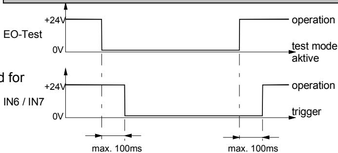
idle status: input IN6 (IN7) gets +24V
triggering: input IN6 (IN7) is open
test mode: When door reaches upper end position the controller waits for a trigger of IN6 (IN7). Therefore the +24V signal of test output "EO-Test" will be switched off. This can be used for example to switch off a transmitter of a one way light barrier or to trigger the test input of a reflex light barrier. (if necessary switch external "Pull-Down resistor" of max. IN6/2,2kΩ from clamp 63 (67) to clamp 64 (68))
The test of the draw-in security device happens only in the upper end position. For the realisation of an intermediate stop ask your supplier.
Note:
| draw-in security not connected | draw-in security connected reflex light barrier | draw-in security connected one way light barrier | |
| channel 1 (INSIDE) | +24V IN7 EO-Test GND wire bridge | transmitter-receiver module +24V IN7 EO-Test GND 64 | +24V IN7 EO-Test GND 64 +24V IN7 EO-Test GND 64 +24V IN6 EO-Test GND 68 +24V IN6 EO-Test GND 68 +24V IN6 EO-Test GND 68 +24V IN6 EO-Test GND 68 +24V IN6 EO-Test GND 68 +24V IN6 EO-Test GND 68 +24V IN6 EO-Test GND 68 +24V IN6 EO-Test GND 68 +24V IN6 EO-Test GND 68 +24V IN6 EO-Test GND 68 +24V IN6 EO-Test GND 68 +24V IN6 EO-Test GND 68 -24V IN6 EO-Test GND 68 -24V IN6 EO-Test GND 68 -24V IN6 EO-Test GND 68 -24V IN6 EO-Test GND 68 -24V IN6 EO-Test GND 68 -24V IN6 EO-Text GND 68 -24V IN6 EO-Test GND 68 -24V IN6 EO-Test GND 68 -24V IN6 EO-Test GND 68 -24V IN6 EO-Test GND 68 -24V IN6 EO-Test GND 68 -23V IN6 EO-Test GND 68 -23V IN6 EO-Test GND 68 -23V IN6 EO-Test GND 68 -23V IN6 EO-Test GND 68 -23V IN6 EO-Test GND 68 -23V IN6 EO-Test gnd -23V IN6 EO-Test GND 68 -23V IN6 EO-Test GND 68 -23V IN6 EO-Test GND 68 -23V IN6 EO-Test GND 68 -23V IN6 EO-Test GND 68 -23V IN6 EON +24V IN6 EO-Test GND 68 -23V IN6 EO-Test GND 68 -23V IN6 EO-Test GND 68 -23V IN6 EO-Test GND 68 -23V IN6 EO-Test GND 68 -23V IN6 EO-Text GND 68 -23V IN6 EO-Test GND 68 -23V IN6 EO-Test GND 68 -23V IN6 EO-Test GND 68 -23V IN6 EO-Test GND 68 -23V IN6 EO-Test GND 68 -24V IN6 EO-Test GND 68 -24V IN6 EO-Test GND 68 -24V IN6 EO-Test GND 68 -24V IN6 EO-Test GND 68 -24V IN6 EO-Test gnd -24V IN6 EO-Test GND 68 -24V IN6 EO-Test GND 68 -24V IN6 EO-Test GND 68 -24V IN6 EO-Test GND 68 -24V IN6 EO-Test GND 68 -24V IN6 EON +24V IN6 EO-Test GND 68 -23V IN6 EO-Test GND 68 -23V IN6 EO-Test GND 68 -23V IN6 EO-Test GND 68 -23V IN6 EO-Test GND 68 -19V IN6 EO-Test GND 68 -19V IN6 EO-Test GND 68 -19V IN6 EO-Test GND 68 -19V IN6 EO-Test GND 68 -19V IN6 EO-Test GND 68 -19V IN6 EO-Test gnd -19V IN6 EO-Test GND 68 -19V IN6 EO-Test GND 68 -19V IN6 EO-Test GND 68 -19V IN6 EO-Test GND 68 -19V IN6 EO-Test GND 68 -19V IN6 EON +24V IN6 EO-Test GND 68 -23V IN6 EO-Test GND 68 -23V IN6 EO-Test GND 68 -23V IN6 EO-Test GND 68 -23V IN6 EO-Test GND 68 -0.5V IN6 EO-Test GND 68 -0.5V IN6 EO-Test GND 68 -0.5V IN6 EO-Test GND 68 -0.5V IN6 EO-Test GND 68 -0.5V IN6 EO-Test GND 68 -0.5V IN6 |
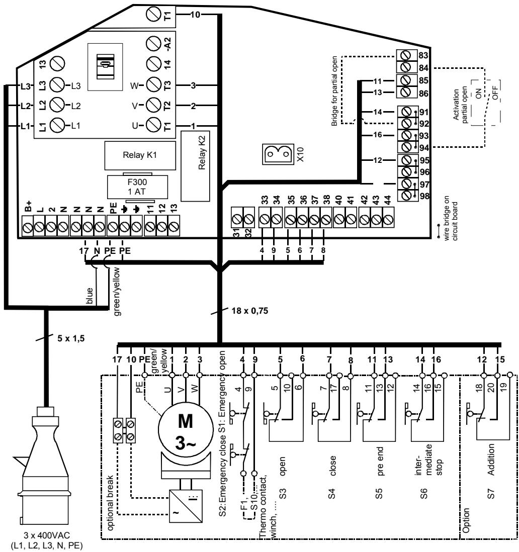
9.2 Appendix B: Wiring of motor and end switches (connection example 1)
9.3 Appendix C: Wiring of motor and end switches (connection example 2)
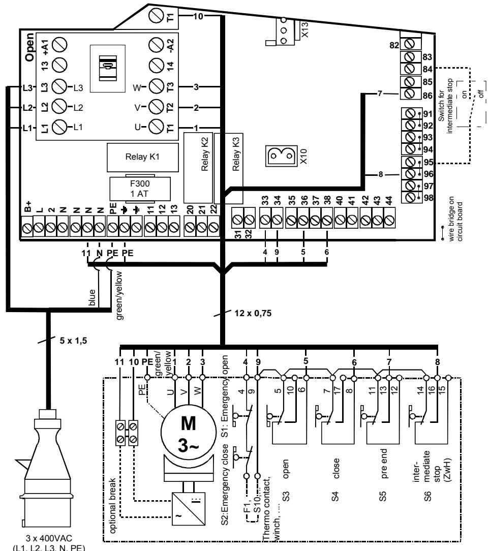
for function intermediate stop:
1.) connection of switch "intermediate ON/OFF" at clamps 83 and 94
2.) adjustment of intermediate stop position with end switch S6 "ZwH"
9.4 Appendix D: Often used standard connections
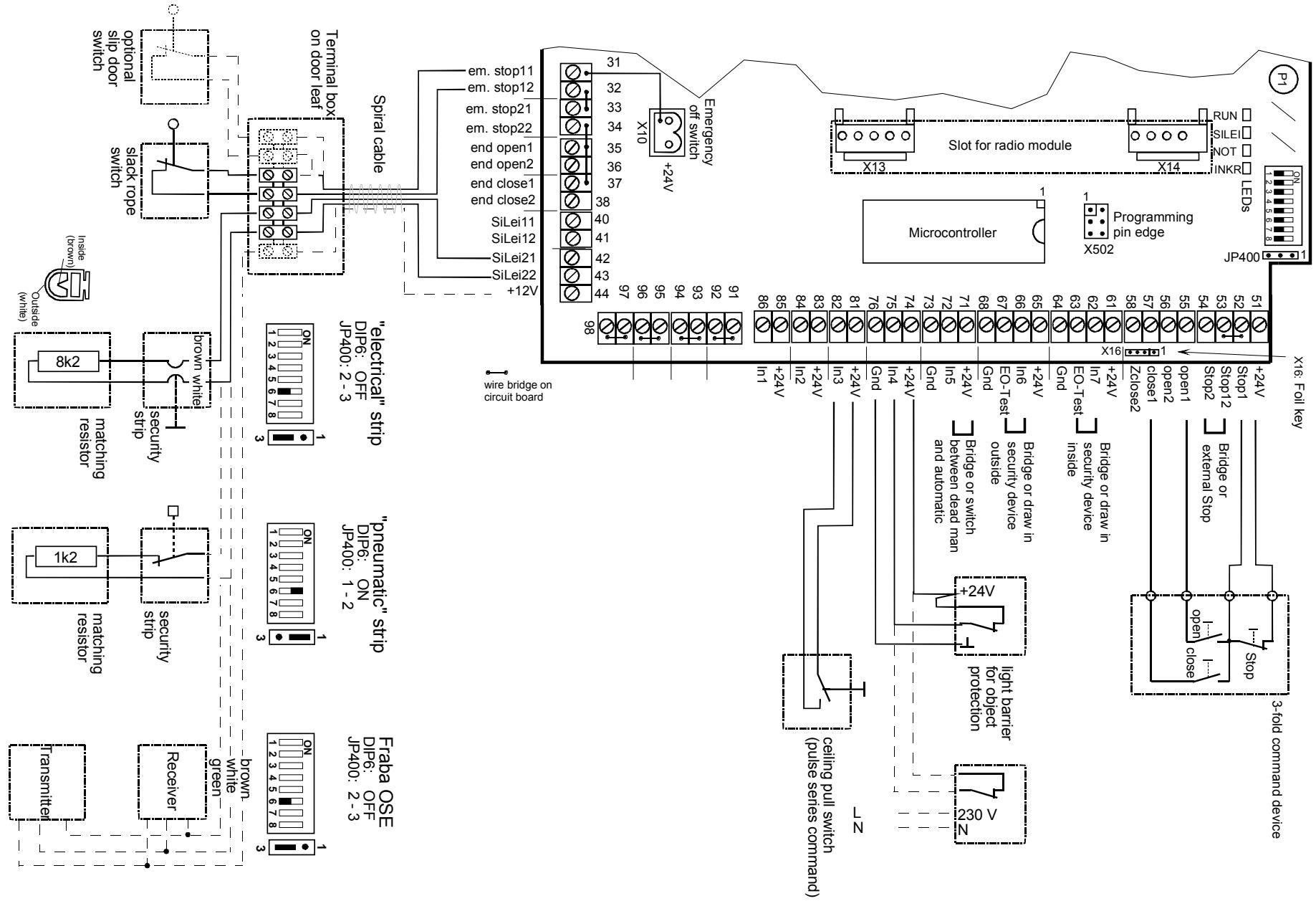
9.5 Appendix E: Overview TST WS-B
Operational description
Operational description