
GZ 685W - Range hood Guzzanti - Free user manual and instructions
Find the device manual for free GZ 685W Guzzanti in PDF.


| Product Type | Range Hood |
| Brand | Guzzanti |
| Model | GZ 685W |
| Installation Type | Wall-mounted (built-in capable) |
| Width | 600 mm |
| Depth | 500 mm |
| Height | 150 mm (without chimney) |
| Weight | 12 kg |
| Power Supply | 220-240 V ~ 50/60 Hz |
| Maximum Power | 200 W |
| Motor Type | Single centrifugal motor |
| Number of Speeds | 3 |
| Maximum Airflow | 350 m³/h |
| Noise Level (max speed) | 60 dB(A) |
| Lighting | 2 x 1.5 W LED |
| Filter Type | Aluminum grease filter (washable) |
| Ducting Options | Ducted (external vent) or recirculation (with charcoal filter) |
| Control Type | Slider switch or push buttons |
| Energy Class | A+ |
| Maintenance | Clean grease filter every 2 months; replace charcoal filter every 4 months |
| Safety Features | Overheat protection, motor thermal cut-out |
| Spare Parts Available | Grease filter, charcoal filter, LED lamps, motor |
| Compliance | CE, RoHS |
Frequently Asked Questions - GZ 685W Guzzanti
User questions about GZ 685W Guzzanti
0 question about this device. Answer the ones you know or ask your own.
Ask a new question about this device
Download the instructions for your Range hood in PDF format for free! Find your manual GZ 685W - Guzzanti and take your electronic device back in hand. On this page are published all the documents necessary for the use of your device. GZ 685W by Guzzanti.
USER MANUAL GZ 685W Guzzanti
OKAP WYSPOWY(WENTYLACYJNY)
KUCHYŃSKÁ VENTILAČNÍ DIGESTOŘ
KUCHYNSKÝ VENTILAČNÝ DIGESTOR
KONYHAI PÁRAELSZIVÓ
natural_image
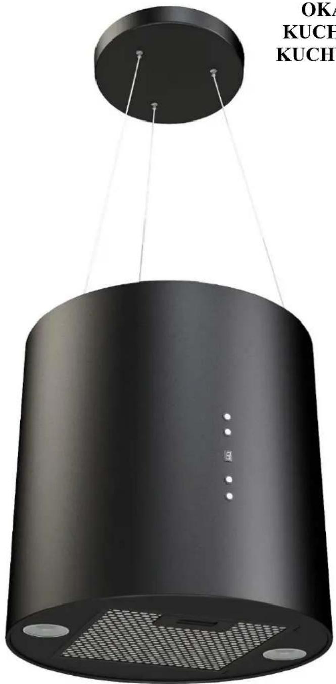
Black cylindrical kitchenpan with hanging wires and ventilation grilles (no text or symbols visible)GZ-685

| EN |
| PL |
| CZ |
| SK |
| HU |
USER'S MANUAL
INSTRUKCJA OBSŁUGI
NÁVOD K OBSLUZE
NÁVOD NA OBSLUHU
ASZNÁLATI UTASITÁS
EN
Dear customer!
Thank you for choosing the products of the brand " GUZZANTI ". We put our best efforts so you were satisfied with your choice.
1. GENERAL INFORMATION
1.1 Prior to installing the extractor hood carefully read our recommendations, following which will provide safe work of the appliance. Save this User's manual, as it contains answers to the questions which may arise later.
BEFORE STARTING THE OPERATION (SWITCHING ON) THE APPLIANCE MUST BE HELD AT THE ROOM TEMPERATURE FOR AT LEAST TWO HOURS.
1.2. This appliance is intended for extraction of polluted air from the space above the cooking appliance, and intended for domestic use and the household environment only.
USE OF THE APPLIANCE IN GOALS OTHER THAN DOMESTIC IS FORBIDDEN. THE RISK OF INJURY AND PROPERTY DAMAGE INCREASES IN CASE OF USE OF THE EXTRACTOR HOOD WITH PURPOSES OTHER THAN INTENDED, WHAT WILL LEAD TO WARRANTY CANCELLATION.
1.3. Use of the extractor hood decreases the content of harmful products of incomplete combustion of natural gas, as well as odors produced during cooking in the air, and prevents pollution of walls, ceiling, and furniture with grease and soot.
1.4. The appliance is an air purifying device of the exhaust type with a diameter fan (turbine), completed with a grease picking aluminum filter (included) and has the option of upgrading with a carbon odor filter. It is manufactured from sheets of carbon steel with a decorative protective coating of powder paints - 360 mm in width.
1.5. The hood works in the recirculation mode (closed air circulation in the kitchen) (see paragraph 5.3).
1.6. Attention! Do not start extractor hood installation before connecting it to electricity network and checking its technical serviceability, and checking all of its functions.
1.7. We recommend that all installation works, connection, and repair of your extractor hood should be carried only by qualified specialists professionally engaged in the execution of such works.
1.8. The manufacturer does not bear responsibility for any damages and failures, caused by incorrect installation, operation, and repair of the extractor hood.
1.9. The manufacturer reserves the right to modify the product in order to improve its quality and technical specifications.
1.10. Technical specifications for the extractor hood are indicated in this manual and on the label attached to the inner surface of the body (access to it opens when the filter is removed).
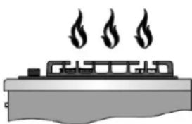
Attention! The extractor hood should be installed on the ceiling at the distance of 650-750mm above the electric cooker and at the distance 750-850 mm above the gas cooker.
- MAIN TECHNICAL SPECIFICATIONS
| Model of kitchen extractor hood | GZ-685 | ||
| Network voltage, V | 220-230 | ||
| AC frequency, Hz | 50 | ||
| Control type | electronic | ||
| Number of operation modes | 4 | ||
| Rated power consumption, W | Of the motor | 220 | |
| Lighting (LED) | 2x3 | ||
| General | 226 | ||
| Productivity while connecting to standard ventilation system m^3 /hour | 668 | ||
| Overall dimensions of the extractor hood, mm | Width | 360 | |
| Depth | 360 | ||
| Height | 360 | ||
| Weight, kg | 8,0 | ||
| Noise level, dB | 45-57 | ||
| Protection class | I | ||
| Operation mode | S1 (long-lasting) | ||
| Electro cable type | Armoured and grounded | ||
- PARTS SUPPLIED
| Item | Quantity |
| Kitchen extractor hood | 1 pcs. |
| The anchor is wedge galvanized M8 ∅10 x 60 mm | 3 pcs. |
| User’s manual | 1 pcs. |
- SAFETY REQUIREMENTS
| ATTENTION! | IT IS FORBIDDEN TO CONNECT THE EXTRACTOR HOOD TO THE NETWORK OF THE ELECTRIC COOKER. PROTECT ELECTRIC CORD FROM MECHANICAL AND THERMAL DAMAGE. |
4.1. While installing, the operation of conducting technical services, it is strictly forbidden to:
-
connect the extractor hood to the electricity network with a voltage and frequency that does not correspond to those specified in paragraph 2;
• use lighting lamps with a power output of more than 1,5 watts (LED); -
carry out maintenance, replace lamps, remove filters, clean the extractor hood without removing the plug from the mains socket;
- operate the extractor hood with an open fire source, open gas burners or heating elements.Heating elements should be always covered with dishes;
• prepare food with use of alcohol; - leave the fryer unattended;
• operate the extractor hood with removed filters; - connect the extractor hood to the electric network of the cooker, cut the socket of the electric cord while installing.
ATTENTION! IT IS FORBIDDEN TO USE GAS (ELECTRIC) COOKER IF THE EXTRACTOR HOOD IS TURNED OFF.
4.2. In order to avoid damage by electric current, the extractor hood must be plugged into a grounded outlet.
4.3. Using the extractor hood together with other heating appliances (gas, oil, ovens, etc.), besides electric, it is necessary to provide the premises, it which the extractor hood is installed with the additional flow of the fresh air (for example to open the window).
4.4 Provide timely cleaning of non-disposable aluminum removal filters, otherwise, the efficiency of the extraction will decrease and there will be a fire hazard due to the accumulation of grease and dust in the filter.
4.5. It is forbidden to turn on the extractor hood in case of ignition with the purpose of reduction of smoke until complete localization of fire.
4.6. In case of ignition under the extractor hood, cover the fire with a thick cloth, disconnect the extractor from the electric network, do not use water to extinguish a fire in the places where the electrical appliances are located.
4.7. Protect the cord for connection to the electric network from the mechanic and thermal damages.
5. EXTRACTOR HOOD DESCRIPTION
5.1. The appliance «GZ-685» is an air purifying device of the exhaust type with a diameter fan (turbine), completed with a grease picking aluminum filter. It is manufactured from sheets of carbon steel with a decorative protective coating of powder paints.
5.2 The hood types is "island", and it is mounted on the ceiling above the stove.
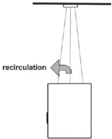
5.3 The hood works in the recirculation mode (closed air circulation in the kitchen) (Pic. 1).
"It is necessary to consider, that when the extractor hood is on, the pressure is automatically lowered in the enclosed room, and should be balanced with an inflow of fresh air. This may be achieved by opening doors and windows or with use of equipment for special inflow ventilation".
natural_image
Illustration of a steam locomotive with three flames above it (no text or symbols)Pic.1
5.4 The cooker hood consists of the next components (Pic.2):
1 - Aluminium filter
2 - LED lamps
3 - Frame
4 - Control panel
5 - Brackets with the clamp of ropes
6 - Charcoal filter
7 - Turbofan
8 - power supply box with power cord
9 - Box with capacitor
10 - Fixing
11 - Body cover
12 - Rope
13 - Fixing (mounting) cover
14 - Cable clamps
15 - Fixing Brackets

Pic.2
6. EXTRACTOR HOOD INSTALLATION INSTRUCTIONS
6.1. Choose a place to install the hood.
6.2. Remove the extractor hood from the packaging.
6.3. Check the work of the extractor hood, connect it to the electric network and check all its functions.
6.4 Pass the metal ropes through the holes of the fixing covers and mounting brackets (diagram 1).
6.5 Strain the clamps on the metal ropes and make a knot (diagram 2, 3, 4).
6.6 Tighten the clamps on the metal ropes as far as they will go (diagram 5).
Hood installation quide


Pic.3
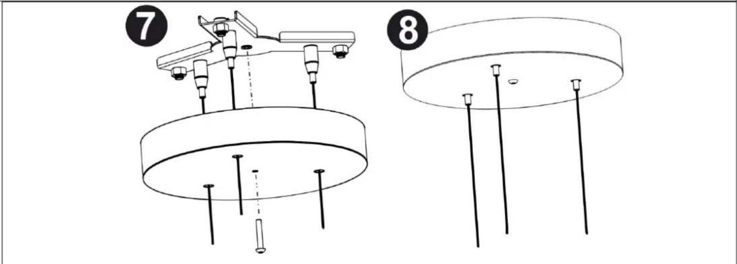
6.7 Drill 3 holes in the ceiling for M8 ∅12x60mm anchors. Lift the mounting brackets to the ceiling and fix the three bolts through the holes in the mounting brackets and tighten the wedges into the anchor (diagram 6).
6.8 Lift the fixing cover to the joint with the mounting brackets (diagram 7).
6.9 Fix the mounting covers with the mounting brackets (diagram 8).
6.10 Check the reliability of an extracts mounting.
7.1 Extractor hoods have 4 ventilation speeds. Depending on the volume of evaporation when cooking, you can select low, middle or high ventilation level.
7.2 Turn on the extractor hood in the needed mode before cooking. It is recommended to continue the work of the extractor hood for 3-5 minutes after cooking, thus the air in the kitchen will be cleared from the residues of evaporation and odors.
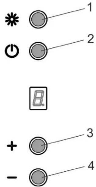
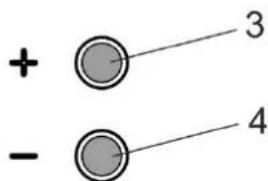
7.3 The switch of the operation modes of the motor and lighting lams is located on the frame of the extractor hood (pic. 4).
1 - Light on/off
2 - Fan on/off
3 - Speed increase
4 - Speed decrease
Pic.4
8. MAINTENANCE INSTRUCTIONS
Attention! Before cleaning the extractor hood, disconnect it from the electricity.
8.1 Use a damp cloth soaked in warm water with a neutral detergent for external cleaning of the painted extractor hood.
8.2 Never use abrasive detergents, coarse sponges or detergents containing soda, acid, chlorides or solvents to clean the extractor hood.
8.3 When cleaning, avoid getting moisture on the current-carrying parts of the extractor hood, and wipe the surfaces with a soft cloth after washing.
8.4 The aluminum filter, holding oil and dust from the air, is clogged and should be washed after being soaked in hot water with an effective detergent once every 1.5 to 2 months. Changing the color of the filter after washing does not affect the quality of its work.
8.5 To remove the aluminum filter, press the spring latch and remove the filter from the panel. Install the filter in reverse order (Pic. 5).

natural_image
Simple line drawing of a mechanical or electrical component with arrows indicating direction (no text or symbols)Pic. 5
Do not install the filter after washing until it is completely dry.
8.6 The carbon filters, used during recirculation mode should be changed every 3-6 months depending on the extractor hood use. Filters are installed on the T-like stab of the cover of the turbofan by axial pushing and clockwise rotation.
8.7 To replace the lamp it is necessary to remove the filters (Pic. 7), pull out the socket, so that the light gets out from the body of the hood, holding the socket press on the lamp lightly in the direction of the socket and, turning it counterclockwise, remove (Pic.6). Instead of it, you need to install a new one with the same characteristics and put the filters.
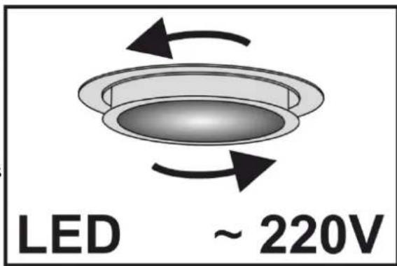
Pic. 6
To change the carbon filter, you need to follow the next steps (pic.7):
1 - Place the carbon filter on the lock until it stops on both sides.
2 - Turn the carbon filter in any direction at an angle of 90 degrees, ensuring fixation.
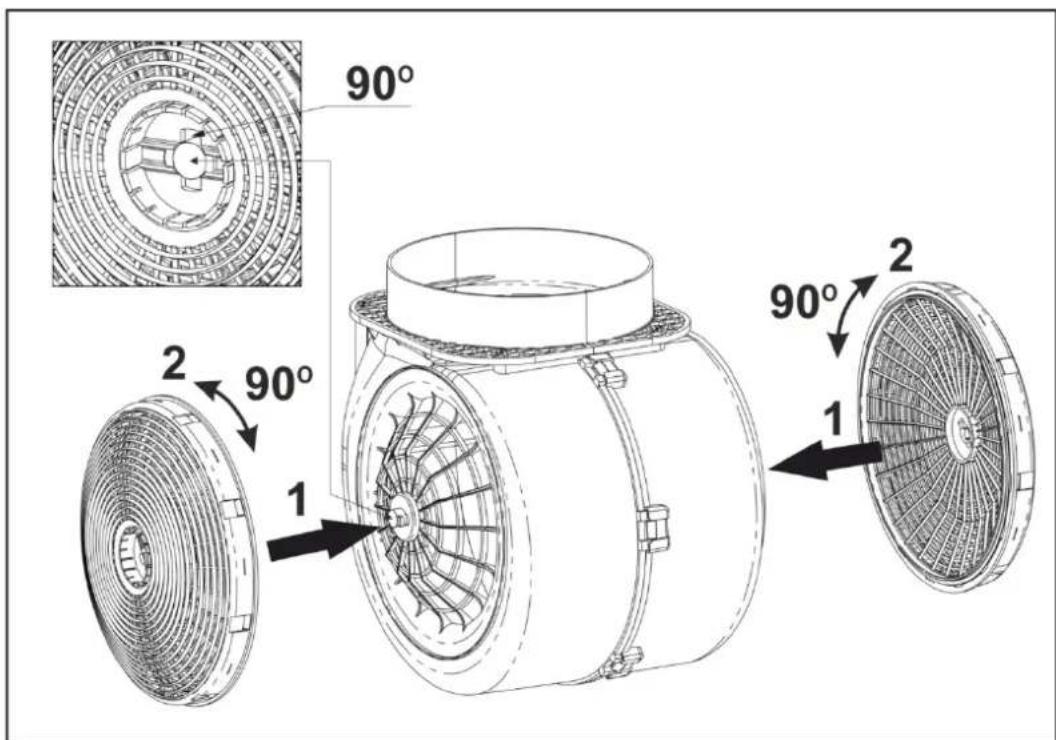
Pic. 7
ELECTRICAL SCHEMATIC DIAGRAM

Possible malfunctions of the extractor hood
| Check connection to the electricity supply. | Check whether the display is turned on. | Check the lamp switch (should be turned on). | Check aluminum filter (should be cleaned once every 1,5-2 months). | Check the socket (For the power connection). | Check lamps. | Check air outlet pipe (for the traction). | Check carbon filter (replacement once every 3-4 months). | |
| Extractor hood does not work. | ● | ● | ● | |||||
| The lamp does not light. | ● | ● | ● | ● | ||||
| Reduced performance of the extractor hood. | ● | ● | ● | |||||
| The extractor hood began to work louder. | ● | ● | ||||||
| Air is poorly drawn in the recirculation mode. | ● | ● |
PL
Drogi kliencie!
natural_image
Illustration of a steamship emitting three flames (no text or symbols)Rys.1
Rys.2
6. INSTRUKCJA MONTAŻU OKAPU


Rys.3
natural_image
Simple line drawing of a mechanical or electrical component with arrows indicating direction (no text or symbols)Rys.5
natural_image
Illustration of a steamship emitting smoke (no text or symbols)Obr.1
Obr.2
6. INSTALACE



Obr.4
8. ÚDRŽBA
natural_image
Pure technical diagram of a mechanical component with directional arrows, no text or symbols presentObr.5
natural_image
Illustration of a steamship emitting three flames (no text or symbols)Obr.1
Obr.2
6. INŠTALÁCIA
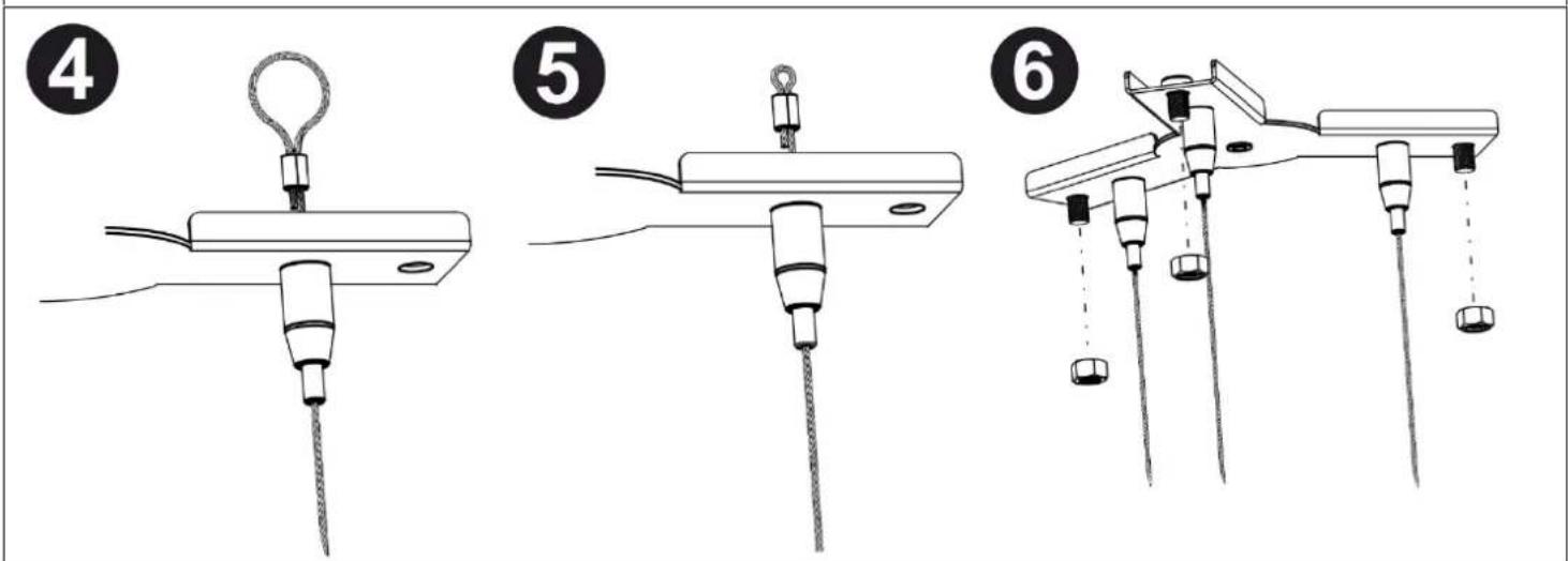

6.4 Prelínajte ocel'ové laná cez otvory na konzolách a cez otvory na montážnych krytoch (schéma 1).
6.5 Nasad'te uchytenia na ocel'ové laná a urobte uzol (schéma 2, 3, 4).
6.6 Ďalej uchytenia na ocel'ových lanách je treba utiahnut' až na doraz (schéma 5).

Obr.4
8. ÚDRŽBA
natural_image
Simple line drawing of a mechanical or electrical component with arrows indicating direction (no text or symbols)Obr.5
natural_image
Illustration of a steam locomotive emitting smoke (no text or symbols)rajz.1
rajz.2


rajz.4
8. PÁRAELSZIVÓ KARBANTARTÁSI UTASITÁSA
natural_image
Simple line drawing of a mechanical or electrical component with arrows indicating direction (no text or symbols)raiz.5


- EN
- Dear customer!
- GENERAL INFORMATION
- BEFORE STARTING THE OPERATION (SWITCHING ON) THE APPLIANCE MUST BE HELD AT THE ROOM TEMPERATURE FOR AT LEAST TWO HOURS.
- USE OF THE APPLIANCE IN GOALS OTHER THAN DOMESTIC IS FORBIDDEN. THE RISK OF INJURY AND PROPERTY DAMAGE INCREASES IN CASE OF USE OF THE EXTRACTOR HOOD WITH PURPOSES OTHER THAN INTENDED, WHAT WILL LEAD TO WARRANTY CANCELLATION.
- ATTENTION! IT IS FORBIDDEN TO USE GAS (ELECTRIC) COOKER IF THE EXTRACTOR HOOD IS TURNED OFF.
- EXTRACTOR HOOD DESCRIPTION
- EXTRACTOR HOOD INSTALLATION INSTRUCTIONS
- MAINTENANCE INSTRUCTIONS
- PL
- Drogi kliencie!
- INSTRUKCJA MONTAŻU OKAPU
- INSTALACE
- ÚDRŽBA
- INŠTALÁCIA
- PÁRAELSZIVÓ KARBANTARTÁSI UTASITÁSA
Brand : Guzzanti
Model : GZ 685W
Category : Range hood