
GZ 443 - Range hood Guzzanti - Free user manual and instructions
Find the device manual for free GZ 443 Guzzanti in PDF.


| Product Type | Range Hood |
| Brand | Guzzanti |
| Model | GZ 443 |
| Installation Type | Built-in (under cabinet) |
| Width | 60 cm (estimated) |
| Electrical Supply | 220-240 V, 50 Hz |
| Minimum Height Above Electric Cooker | 65-75 cm |
| Exhaust Modes | Extraction (ducting) or Recirculation (with charcoal filter) |
| Duct Diameter | 150 mm / 120 mm |
| Grease Filter Type | Aluminum mesh, washable |
| Charcoal Filter | Optional, not included (for recirculation mode) |
| Lighting | Integrated lamp (LED type likely) |
| Number of Speeds | 3 (assumed based on typical models) |
| Noise Level | Approx. 55-65 dB (typical for this class) |
| Weight | About 10-15 kg |
| Control Type | Push buttons or slider (not specified) |
| Safety Features | Overheat protection, automatic shut-off (assumed) |
Frequently Asked Questions - GZ 443 Guzzanti
User questions about GZ 443 Guzzanti
0 question about this device. Answer the ones you know or ask your own.
Ask a new question about this device
Download the instructions for your Range hood in PDF format for free! Find your manual GZ 443 - Guzzanti and take your electronic device back in hand. On this page are published all the documents necessary for the use of your device. GZ 443 by Guzzanti.
USER MANUAL GZ 443 Guzzanti
Kitchen ventilation hood
Kitchen ventilation hood
Kitchen exhaust hood
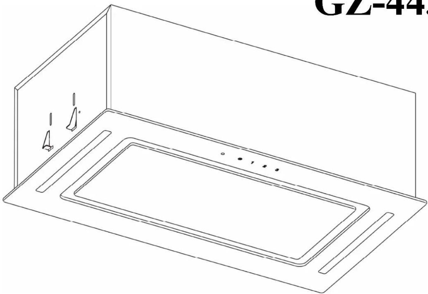
GZ-443

| EN |
| Pt' |
| RZ |
| SK |
| HU |
USER'S MANUAL INSTRUKCJA OBSŁUGI NÁVOD K OBSLUZE NÁVOD NA OBSLUHU HASZNÁLATI UTASÍTÁS
EN
Dear customer!
Fig. 2
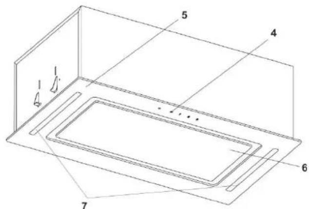
Fig. 3
1 - filter holder 2 - air outlet adapter (diameter ∅150 or ∅120 mm) 3 - electric control panel 4 - switch for the filter holder operating mode (on/off) 5 - decorative panel (external glass) 6 - decorative panel (internal glass) 7 - lighting (LED strip)
6. EXTRACTOR HOOD INSTALLATION INSTRUCTIONS
6.1. Select the operating mode and place for installation of the extractor hood. 6.2. Remove the extractor hood from the packaging. 6.3. Check the filter in the extractor hood, connect it to the electric network and check all its functions. 6.4. Taking into account the external height and for the filter hood to fit to the bottom of the lower shelf of the wall cabinet according to a previously made hole pattern, mark and cut a rectangular hole according to the dimensions A3B (Fig. 4) in the upper part of the hood.
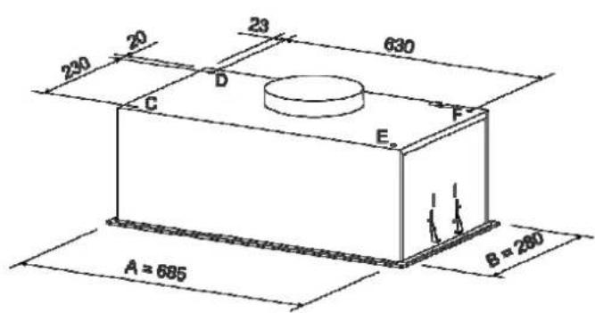

Fig. 4
6.5 Cooker hood for recirculation version no. 1
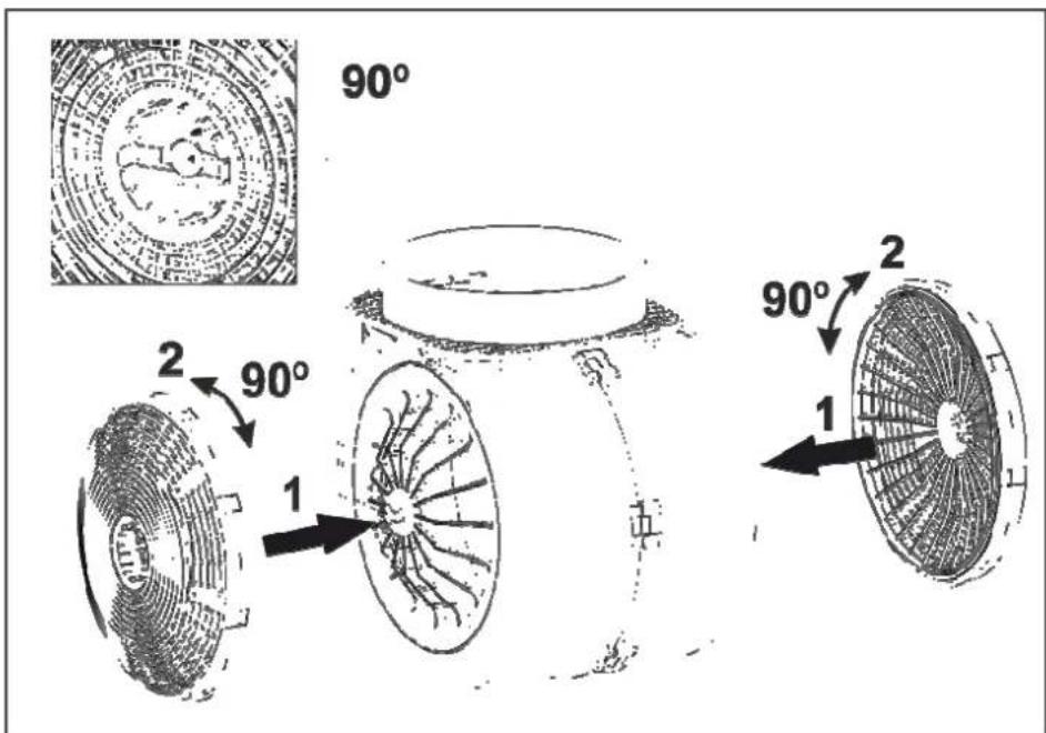
6.5.1 Move the cooker into its final position at 0.5 turns (see detail 1 in Fig. 5). Thereafter, open the inner glass and let the grease-absorbing aluminum filter.
6.5.2 Move the cooker further underneath the nut at 5 turns (not completely underneath) (see detail 2 in Fig. 5) in both directions.
6.5.3 Insert the hood into the slotted rectangular hole at gentle pressure in the elastic clamps (Fig. 5). Move the cooker further and tighten the nut in both directions (detail 2 in Fig. 5) until the hood is snugly attached to the bottom of the filter shelf of the wall cabinet.
6.5.4 Install the grease-absorbing aluminum filter, close the inner glass.

Fig. 5
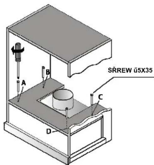
Fig. 5.1

Fig. 5.2
6.6 Cooker hood installation version 2
6.6.1 Make a drilling pattern with the dimensions of the CDE holes (Fig. 4), attach the pattern to the shelves of the furniture set (Fig. 5.1).
6.6.2 Start and drill 4 holes with ∅6mm drill
6.6.3 Fastening the hood as carried out with 4 metric screws M5x35, which are screwed underneath the wall cabinet and the M5 threaded nuts, riveted to the upper side of the hood.
6.7 If necessary, install an air outlet adapter (∅150 / 120 mm).
6.8 If the hood is built into the mine of exhausting air and the channel, mount the selected duct with diameter according to the instructions (Fig. 5.2), ensuring its tightness. Please note that the shorter and more direct the duct, the higher the performance and less noise and vibration in the hood.
6.9 If the hood is operated in recirculation mode, then the duct is not needed. A carbon linear-absorbing filter (to be purchased separately) must be installed.
6.10 Check that the hood is securely fastened, level, and connect the chimney to the mains through the socket.
6.11. Check the real alignment of the mounting of the extractor hood, then connect the column to the object of the electrical connection.
Fig. 9

Fig. 10
ELECTRICAL SCHEMATIC DIAGRAM
| The lamp does not Light. | The contractor hood area to York louder. | The contractor hood area to York louder. | The contractor hood area to York louder. | The contractor hood area to York louder. | The contractor hood area to York louder. | The contractor hood area to York louder. | The contractor hood area to York louder. | The contractor hood area to York louder. | The contractor hood area to York louder. | The contractor hood area to York louder. | The contractor hood area to York louder. | The contractor hood area to York louder, | The contractor hood area to York louder, | The contractor hood area to York louder, | The contractor hood area to York louder, | The contractor hood area to York louder, | The contractor hood area to York louder, | The contractor hood area to York louder, | The contractor hood area to York louder, | The contractor hood area to York louder, | The contractor hood area to York louder, | The contractor hood area to York louder, | The contractor hood area to York louder, | ||||||||||||||||||||||||||||||||||||||||||||||||||||||||||||||||||||||||||||
Pt.
Drop clearance!
Fig. 2
Distance H:
To electric cooker 65-75cm
Fig. 5

Fig. 5.1
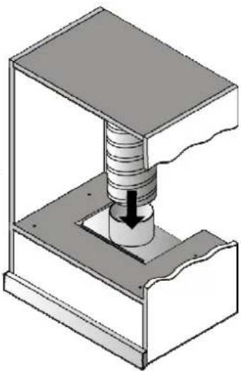
Fig. 5.2
Fig. 8
| Lampa nac BRACCA | ZmAlvesona produktibnosci preci okapu | Okap pracuje grosnajci | W triac recrnuclajA Rupusceca Sag mało pobateria | |
| ● | ● | ● | ● | |
| ● | ● | ● | ● | |
| ● | ● | ● | ● | |
| ● | ● | ● | ● | |
| ● | ● | ● | ● | |
| ● | ● | ● | ● | |
| ● | ● | ● | ● | |
| ● | ● | ● | ● | |
| ● | ● | ● | ● | |
| ● | ● | ● | ●, alektrucenc | |
| ● | ● | ● | ● | |
| ● | ● | ● | ● | |
| ● | ● | ● | ● | |
| ● | ● | ● | ● | |
| ● | ● | ● | ● | |
| ● | ● | ● | ● | |
| ● | ● | ● | ● | |
| ● | ● | ● | ● | |
| ● | ● | ● | ●. | |
| ● | ● | ● | ● | |
| ● | ● | ● | ● | |
| ● | ● | ● | ● | |
| ● | ● | ● | ● | |
| ● | ● | ● | ● | |
| ● | ● | ● | ● | |
| ● | ● | ● | ● | |
| ● | ● | ● | ● | |
| ● | ● | ● | ●; | |
| ● | ● | ● | ● | |
| ● | ● | ● | ● | |
| ● | ● | ● | ● | |
| ● | ● | ● | ● | |
| ● | ● | ● | ● | |
| ● | ● | ● | ● | |
| ● | ● | ● | ● | |
| ● | ● | ● | ● | |
| ● | ● | ● | ●: | |
| ● | ● | ● | ● | |
| ● | ● | ● | ● | |
| ● | ● | ● | ● | |
| ● | ● | ● | ● | |
| ● | ● | ● | ● | |
| ● | ● | ● | ● | |
| ● | ● | ● | ● | |
| ● | ● | ● | ● | |
| ● | ● | ● | ● : | |
| ● | ● | ● | ● : | |
| ● | ● | ● | ● : | |
| ● | ● | ● | ● : | |
| ● | ● | ● | ● : | |
| ● | ● | ● | ● : | |
| ● | ● | ● | ● : | |
| ● | ● | ● | ● : | |
| ● | ● | ● | ● : | |

Fig. 3
Fig. 9
ELECTRICAL LOAD DIAGRAM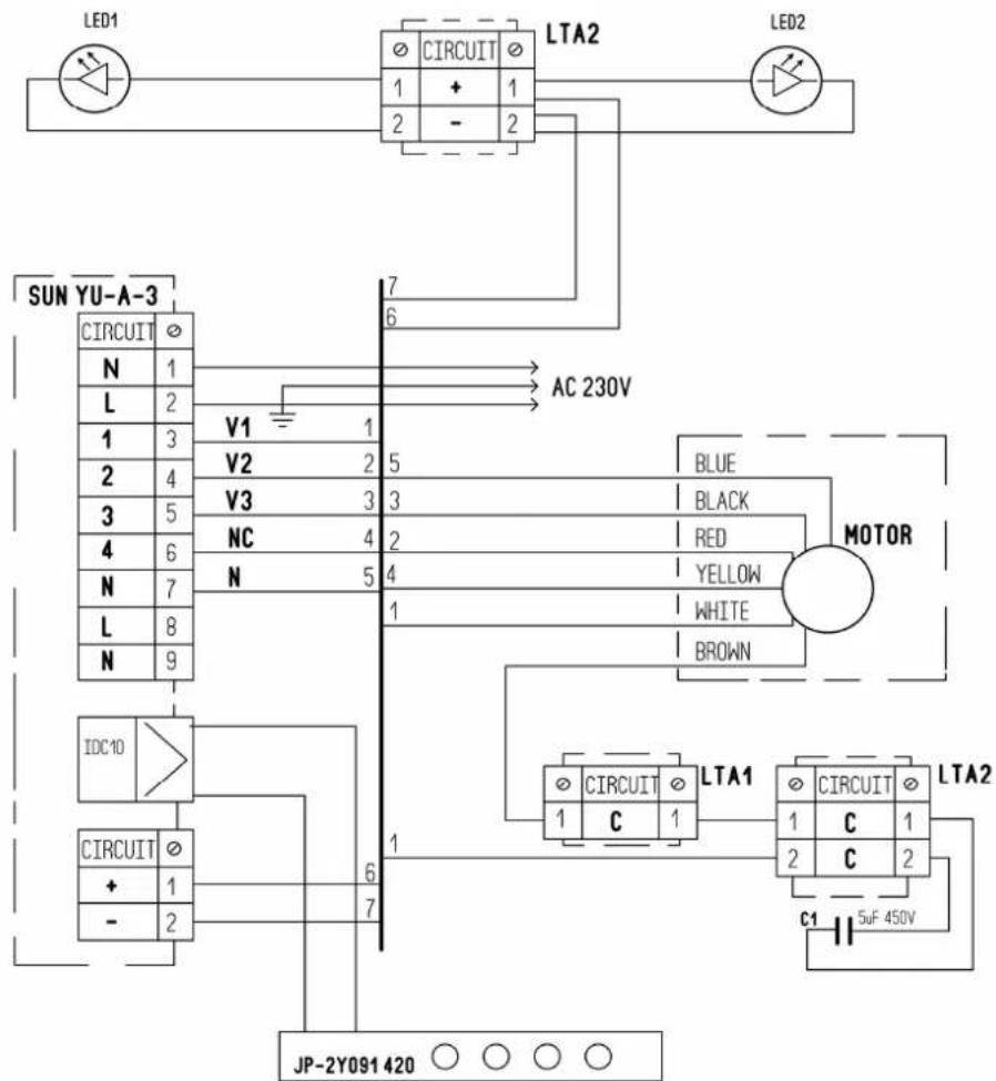
SOLVING OPERATIONAL PROBLEMS
Fig. 1

Fig. 2
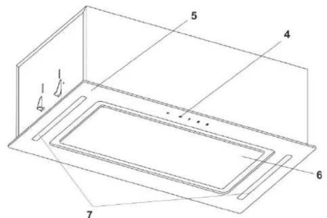
Fig. 3
Fig. 5

Fig. 5.1

Fig. 5.2
6.6 Installation options for the motor. 2
Fig. 1

Fig. 2

Fig. 3
Fig. 5
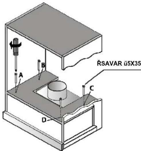
Fig. 5.1

Fig. 5.2
Fig. 9
Fig. 10
ELECTRICAL DIAGRAM


Brand : Guzzanti
Model : GZ 443
Category : Range hood