
GT5O - Water heater GORENJE - Free user manual and instructions
Find the device manual for free GT5O GORENJE in PDF.


| Product Type | Electric Storage Water Heater |
| Brand | Gorenje |
| Model | GT5O |
| Capacity | 50 liters |
| Dimensions (H x W x D) | Approx. 550 x 400 x 450 mm |
| Weight | Approx. 18 kg |
| Power Supply | 220-240 V, 50 Hz |
| Heating Power | 2000 W |
| Maximum Temperature | 75 °C |
| Energy Efficiency Class | B |
| Standby Consumption | 0.5 kWh/24h |
| Overheat Protection | Yes, with automatic shut-off |
| Pressure Relief Valve | Included, rated 8 bar |
| Anti-Corrosion Anode | Magnesium anode, replaceable |
| Insulation | Polyurethane foam, 40 mm |
| Installation Type | Wall-mounted vertical |
| Connection | G 1/2 inch inlet/outlet |
| Control Type | Mechanical thermostat with knob |
| Display | No display, indicator light |
| Material | Steel tank with enamel coating |
| Protection Class | IP24 |
| Maintenance | Annual descaling and anode check |
| Spare Parts | Thermostat, heating element, anode available |
| Warranty | 2 years |
Frequently Asked Questions - GT5O GORENJE
User questions about GT5O GORENJE
0 question about this device. Answer the ones you know or ask your own.
Ask a new question about this device
Download the instructions for your Water heater in PDF format for free! Find your manual GT5O - GORENJE and take your electronic device back in hand. On this page are published all the documents necessary for the use of your device. GT5O by GORENJE.
USER MANUAL GT5O GORENJE
natural_image
White gas water heater with red and blue connectors at the bottom (no visible text or symbols)
natural_image
White cylindrical water heater with red and blue connectors, labeled 'gorenje' (no other text or symbols visible)GT 5-15

Instructions for Use 17

The appliance may be used by children older than 8 years old, elderly persons and persons with physical, sensory or mental disabilities or lacking experience and knowledge, if they are under supervision or taught about safe use of the appliance and if they are aware of the potential dangers.
Children should not play with the appliance.
Children should not clean or perform maintenance on the appliance without supervision.
Installation should be carried out in accordance with the valid regulations and according to the instructions of the manufacturer and by qualified staff.
In a closed, pressurised system of installation, it is obligatory to install a safety valve on the inlet pipe with a rated pressure of 0.6 MPa (6 bar), 0.9 MPa (9 bar) or 1.0 MPa (10 bar) (see the label), which prevents the elevation of pressure in the boiler by more than 0.1 MPa (1 bar) above the rated pressure.
Water may drip from the outlet opening of the safety valve, so the outlet opening should be set to atmospheric pressure.
The outlet of the safety valve should be installed facing downwards and in a non-freezing area.
To ensure proper functioning of the safety valve, the user should perform regular controls to remove limescale and make sure the safety valve is not blocked.
Do not install a stop valve between the water heater and the safety valve, because it will impair the pressure protection of the heater!
Before connecting it to the power supply, the water heater must be filled with water!
The heater is equipped with an additional thermal cut-off for protection in case of failure of the operating thermostat. In this case, however, the temperature of the water in the heater can reach up to 130 °C according to the safety standards. During the water supply installation, the possibility of temperature overloads should be taken into account.
If the heater is to be disconnected from the power supply, please drain any water from the heater to prevent freezing.
⚠️ Please do not try to fix any defects of the water heater on your own. Call the nearest authorised service provider.

Our products incorporate components that are both environmentally safe and harmless to health, so they can be disassembled as easily as possible and recycled once they reach their final life stage.
Recycling of materials reduces the quantity of waste and the need for production of raw materials (e.g. metals) which requires a substantial amount of energy and causes release of harmful substances. Recycling procedures reduce the consumption of natural resources, as the waste parts made of plastic and metal can be returned to various production processes. For more information on waste disposal, please visit your waste collection centre or the store where the product was purchased.
Dear buyer, thank you for purchasing our product. Prior to the installation and first use of the electric water heater, please read these instructions carefully.
This water heater has been manufactured in compliance with the relevant standards and tested by the relevant authorities as indicated by the Safety Certificate and the Electromagnetic Compatibility Certificate. Its technical characteristics are indicated on the label on the bottom of the heater next to the pipes. The installation must be carried out by qualified staff. All repairs and maintenance work within the water heater, e.g. lime removal or inspection/replacement of the protective anticorrosion anode, must be carried out by an authorised maintenance service provider.
INSTALLATION
The water heater should be installed in a room protected from the onset of freezing conditions and located as close as possible to the points of use. It has to be fitted to the wall using appropriate wall screws with a minimum diameter of 5 mm.
With regard to the needs, you can chose execution above the sink (GT 5 O, GT 10 O; GT 15 O) or an execution under the sink (GT 5 U, GT 10 U; GT 15 U).
Dimensions of the water heater for installation and connection [mm]

Installation above the basin/sink

Installation below the basin/sink
| A | B | C | D | E | |
| GT 5 O | 396 | 270 | 256 | 260 | |
| GT 5 U | 396 | 144 | 256 | 260 | |
| GT 10 O | 500 | 398 | 350 | 265 | |
| GT 10 U | 500 | 122 | 350 | 265 | |
| GT 15 O | 500 | 398 | 350 | 310 | |
| GT 15 U | 500 | 122 | 350 | 310 |
CONNECTION TO THE WATER SUPPLY
Z
The water heater connections for the inlet and outlet of water are colour-coded. The inlet of cold water is marked with blue colour, while the hot water outlet is marked with red colour.
The water heater can be connected to the water supply in two ways. The closed-circuit pressure system enables several points of use, while the open-circuit gravity system enables a single point of use only. The mixer taps must also be installed in accordance with the selected installation mode.
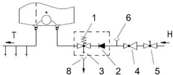
In a closed, pressurized system pressurised mix taps should be used at the outlet points. To ensure safe operation of the heater a safety valve should be installed on the inlet pipe to prevent elevation of pressure for more than 0.1 MPa (1 bar) above the nominal pressure. The outlet opening on the safety valve must be equipped with an outlet for atmospheric pressure. The heating of water in the heater causes the pressure in the tank to increase to the level set by the safety valve. As the water cannot return to the water supply system, this can result in dripping from the outlet of the safety valve. The drip can be piped to the drain by installing a catching unit just below the safety valve. The drain installed below the safety valve outlet must be piped down vertically and placed in an environment that is free from the onset of freezing conditions.
To avoid water dripping from the safety valve, an expansion tank should be installed on the inlet pipe of the heater with the capacity of at least 5 % of the heater volume.
To ensure proper operation of the safety valve, periodical inspections must be carried out to remove limescale and make sure the safety valve is not blocked.
To check the valve, open the outlet of the safety valve by turning the handle or unscrewing the nut of the valve (depending on the type of the valve). The valve is operating properly if the water comes out of the nozzle when the outlet is open.
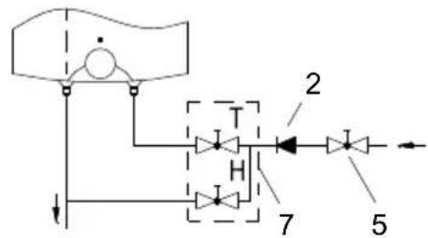
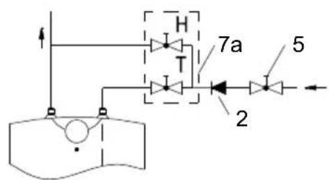
An open-circuit, non-pressurised system requires the installation of a non-return valve at the water inlet to prevent water draining out from the tank in the event of the water supply running dry. This installation mode requires the use of an instantaneous mixing tap.
As the heating of water expands its volume, this causes the tap to drip. The dripping cannot be stopped by tightening it further; on the contrary, the tightening can only damage the tap.
Open-circuit (gravity) system
Installation above the basin/sink
Closed-circuit (pressure) system
Installation above the basin/sink

Installation below the basin/sink

Installation below the basin/sink
Legend:
1 - Safety valve
2 - Non-return valve
3 - Test valve
4 - Pressure reduction valve
5 - Closing valve
6 - Checking fitting
7 - Mixer tap - installation above the basin/sink
7a - Mixer tap - installation below the basin/sink
8 - Funnel with outlet connection
H - Cold water
T - Hot water
No closing valve may be built-in between the water heater and return safety valve, because with it the pressure protection would be impeded! The heater can be connected to the domestic water supply network without a pressure-reducing valve if the pressure in the network is lower than the nominal pressure. If the pressure in the network exceeds the nominal pressure, a pressure-reducing valve must be installed.
Before connecting it to the power supply, the water heater must be filled with water. When filling the heater for the first time, the tap for the hot water on the mixing tap must be opened. When the heater is filled with water, the water starts to run through the outlet pipe of the mixing tap.
CONNECTING THE WATER HEATER TO THE POWER SUPPLY NETWORK
The water heater shall be connected to the power supply by an electrical cable fitted with a plug. Should the existing cable replaced by a new, longer cable, the new cable should be connected to the lead and the wires screwed to the connectors. In this
case the water heater should first be disconnected from the power supply.
Connecting the heater to the power supply network must take place in accordance with the standards for electric appliances. To comply with the national installation regulations, an all poles disconnect switch must be installed between the water heater and the power supply network.
Legend:
1 - Thermostat
2 - Thermal fuse
3 - Heating element
4 - Light indicator
5 - Connection terminal
L - Live conductor
N - Neutral conductor
÷ - Earthing conductor

Electric installation
CAUTION: Before any intervention into the interior of the water heater, disconnect it from the power supply network! This intervention may only be performed by a trained professional!
The water heater is ready for use once it has been connected to water and power. By turning the thermostat knob on the front side of the protective cover, water temperature can be set between "*" frost protection position and "●" approx 75 °C position. We recommend that the knob be set to position "e" as this ensures the most economic operation of the water heater. This way the water temperature is maintained at approx. 35 °C by (GT 10 and GT 15) and and approx 41 °C by (GT 5). The operation of the heater at this temperature level also results in reduced build-up of calcium and lime, as well as reduced heat loss than is the case at higher temperatures. Due to safety reasons you can optionally set the highest temperature value of water in the heater. Proceed as follows:

a) Insert screwdriver in slot 1 and remove button cover 2, b) Set knob limiter 3 to any desired temperature value,
C: 35^ C
B: 45^ C
A: 55^ C
O: 75^ C
c) Replace knob cover 2 to the knob.
The operation of the heating element is indicated by the light indicator that stays on until the temperature in the tank has reached the set level or until the heater has been deliberately switched off. When the water heater is not in use for longer periods of time, it should be protected from freezing by setting the
temperature to " *". Do not disconnect the power. Thus the temperature of the water in the tank is maintained at about 9 °C. Should you choose to disconnect the power, the water heater should be thoroughly drained before the onset of freezing conditions. Water from the heater is drained through the inlet/outlet pipe of the heater.
The exterior of the water heater may be cleaned with a mild detergent solution. Do not use solvents and abrasive cleaners.
Regular preventive maintenance inspections ensure faultless performance and long life of your heater. The first of these inspections should be carried out by the authorised maintenance service provider about 36 months from the date of installation in order to check the wear of the protective anticorrosion anode and remove any build-up of calcium and lime as required. The build-up of calcium and lime in the water heater depends on the quality, quantity and temperature of water flowing through the heater. The maintenance service provider shall also issue a condition report and recommend the approximate date of the next inspection.
In the event of the heater breaking down, you are kindly requested to contact the authorised maintenance service provider located closest to you. Please do not attempt to carry out any repairs yourself.
TECHNICAL PROPERTIES OF THE APPLIANCE
| Type | GT 5O | GT 5U | GT 10O | GT 10U | GT 15O | GT 15U | |
| Declared load profile | XXS | XXS | XXS | XXS | XXS | XXS | |
| Energy efficiency class ^1) | A | A | A | A | A | A | |
| Water heating energy efficiency (ηwh) ^1) | [%] | 35,9 | 35,2 | 36,3 | 35,2 | 36,1 | 35,3 |
| Annual electricity consumption ^1) | [kWh] | 514 | 525 | 508 | 524 | 510 | 523 |
| Daily electricity consumption ^2) | [kWh] | 2,410 | 2,480 | 2,377 | 2,461 | 2,391 | 2,465 |
| Thermostat temperature settings | e | ||||||
| Value of "smart" | 0 | 0 | 0 | 0 | 0 | 0 | |
| Volume | [l] | 6,2 | 6,6 | 9,8 | 9,9 | 14,8 | 14,9 |
| Rated pressure | [[MPa(bar)] | 0,6 (6) / 0,9 (9) / 1,0 (10) | |||||
| Weight / Filled with water | [kg] | 6,8 / 11,8 | 8 / 18 | 11 / 26 | |||
| Anticorrosion protection of the tank | Enamelled / Mg anode | ||||||
| Power of electrical heater | [W] | 2000 | |||||
| Voltage | [V~] | 230 | |||||
| Protection class | I | ||||||
| Degree of protection | IP24 | ||||||
| Heating time from 10 °C to 65 °C | [min] | 11 | 20 | 29 | |||
| Packaging dimensions | [mm] | 300x300x440 | 300x400x530 | 350x400x530 | |||
^1) EU Regulation 812/2013; EN 50440
2) EN 50440
WE RESERVE THE RIGHT TO MAKE CHANGES THAT DO NOT IMPAIR THE FUNCTIONALITY OF THE DEVICE.
The user manual can also be found at our website http://www.gorenje.com.
FIGYELEM
ZACHOWUJEMY PRAWO DO ZMIAN, KTÓRE NIE WPŁYWWAJĄ NA FUNKCJONALNOŚĆ.
Varianta "deasupra chiuvetei"
Typ nad umyvadlom
Typ nad umyvadlom
Typ pod umyvadlom

Typ pod umyvadlom
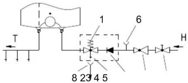
LEGENDA:
a) Vložte skrutkovač do dražky 1 a odstráňte kryt tlačidla 2,
b) Obmedzovač tlačidla 3 a potom l'ubovoľne nastavťe požadovanú teplotu:
C: 35 °C
B: 45^ C
A: 55^ C
O: 75^ C
c) Kryt tlačidla 2 vstavte na ram tlačidla.
Varianti mbi sqoll

Varianti mbi sqoll

Varianti nën sqoll

Varianti nën sqoll
Legjenda:
1 - Valvuli sigurues
2 - Valvuli jo-kthyes (ireverzibil)
3 - Valvuli provues
4 - Valvuli reduktues i shtypjes
5 - Valvuli mbyllës
6 - Shtojca provuese
7 - Bateria përzierëse mbi sqoll


- GT 5-15
- Dear buyer, thank you for purchasing our product. Prior to the installation and first use of the electric water heater, please read these instructions carefully.
- INSTALLATION
- CONNECTION TO THE WATER SUPPLY
- Legend:
- CONNECTING THE WATER HEATER TO THE POWER SUPPLY NETWORK
- TECHNICAL PROPERTIES OF THE APPLIANCE
- FIGYELEM
- LEGENDA:
- Legjenda:
Brand : GORENJE
Model : GT5O
Category : Water heater