PSR 18 VE-2 - Drill BOSCH - Free user manual and instructions
Find the device manual for free PSR 18 VE-2 BOSCH in PDF.

User questions about PSR 18 VE-2 BOSCH
0 question about this device. Answer the ones you know or ask your own.
Ask a new question about this device
Download the instructions for your Drill in PDF format for free! Find your manual PSR 18 VE-2 - BOSCH and take your electronic device back in hand. On this page are published all the documents necessary for the use of your device. PSR 18 VE-2 by BOSCH.
USER MANUAL PSR 18 VE-2 BOSCH
Operating instructions
Nickel-Cadmium-Akku:
Dr. Egbert Schneider Senior Vice President Engineering
Dr. Eckerhard Strötgen
Head of Product Certification


| Cordless screwdriver | PSR 9,6 VE-2 | PSR 12 VE-2 | PSR 14,4 VE-2 | PSR 18 VE-2 | |
| Order number | 0 603 943 6.. | 0 603 943 5.. | 0 603 943 4.. | 0 603 943 3.. | |
| No-load speed | |||||
| 1st gear | [rpm] | 0-390 | 0-390 | 0-400 | 0-400 |
| 2nd gear | [rpm] | 0-1 250 | 0-1 250 | 0-1 250 | 0-1 250 |
| Torque adjustment range | [Nm] | 0.7-9.0 | 0.7-9.0 | 0.7-9.0 | 0.7-9.0 |
| max. torque for hard/soft screwdriving application according to ISO 5393 | [Nm] | 22/8 | 24/12 | 30/16 | 42/22 |
| Maximum drilling Ø (1st/2nd gear) | |||||
| Steel | [mm] | 10/8 | 10/10 | 10/10 | 12/12 |
| Wood | [mm] | 18/16 | 20/19 | 28/20 | 30/22 |
| Screw diameter, max. | [mm] | 6 | 6 | 7 | 8 |
| Chuck clamping range | [mm] | 1-10 | 1-10 | 1-10 | 1-10 |
| Drill spindle thread | 3/8" | 3/8" | 3/8" | 3/8" | |
| Weight without battery, approx. | [kg] | 1.0 | 1.0 | 1.0 | 1.2 |
| Battery | |||||
| Temperature control | NTC | NTC | NTC | NTC | |
| Rated voltage | [V=] | 9.6 | 12 | 14.4 | 18 |
| Capacity | [Ah] | 1.5 | 1.5 | 1.5 | 1.5 |
| Weight, approx. | [kg] | 0.5 | 0.6 | 0.75 | 1.0 |
| Please observe the order number of your machine. The trade names of the individual machines may vary. | |||||
Machine Elements
1 Gear selector
2 Torque setting ring
3 Keyless chuck
4 On/Off switch
5 Rotational direction switch
6 Screwdriver bit
7 Battery
8 Battery unlocking button
9 Soft grip
10 Display
11 Screwdriver attachment (bit)
12 Universal bit holder
13 Locking screw
14 Allen key*
- Not all of the accessories illustrated or described are included as standard delivery.
Intended Use
The machine is intended for the screwing in and loosening of screws as well as for drilling in wood, metal, ceramic and plastic.

For Your Safety

Working safely with this machine is possible only when the operating and safety information are read completely and the instructions contained therein are strictly followed. In addition, the
general safety notes in the enclosed booklet must be observed.
Wear safety goggles.
For long hair, wear hair protection. Work only with closely fitting clothes.
Before each use, check the machine and battery. If damage is detected, do not use the machine. Have repairs performed only by a qualified technician. Never open the machine yourself.
Before any work on the machine itself (e. g. maintenance, tool change, etc.) as well as when transporting and storing, always set the rotational direction switch to the centre position. Otherwise danger of injury is given when unintentionally actuating the On/Off switch.

- Convince yourself before using that the battery is securely seated in the machine.
Use appropriate detectors to determine if utility lines are hidden in the work area or call the local utility company for assistance.
Contact with electric lines can lead to fire and electric shock. Damaging a gas line can lead to explosion. Penetrating a water line causes property damage.
Hold the machine tightly: When driving in screws, high reaction moments can briefly occur.
- Secure the workpiece. A workpiece clamped with clamping devices or in a vice is held more secure than by hand.
■ Never allow children to use the machine.
Bosch is only able to ensure perfect operation of the machine if the original accessories intended for it are used.
Battery and Battery Charger
The enclosed operating instructions for the battery charger must be read carefully!
- Do not open the battery, and protect it from impact. Store in a dry and frost-free place.
■ Allow a heated battery to cool before charging.
- Protect the battery from heat and fire: Danger of explosion! Do not place the battery on radiators or expose to strong sun rays for a longer time; temperatures over 50^ cause damage.
- Do not dispose of the battery in household waste or discard into fire or water.
Before Putting into Operation
Battery Charging
A battery that is new or has not been used for a longer period does not develop its full capacity until after approximately 5 charging/discharging cycles.
To remove the battery 7, press the unlocking buttons 8 and pull out the battery downwards. Do not exert any force.
The battery is equipped with an NTC temperature control which allows charging only within a temperature range of between 0^ and 45^ . A long battery service life is achieved in this manner.
A significantly reduced working period after charging indicates that the batteries are used and must be replaced.
Observe the notes on environmental protection.
Changing the Tool
Open the drill chuck 3 by turning until the tool can be inserted. Insert the tool.
Firmly tighten the sleeve of the keyless chuck 3 by hand. This automatically locks the chuck.
Rotate the sleeve in the reverse direction to remove the tool.
Screwdriving (see figure A)
Directly clamp the screwdriver bit 6 into the drill chuck or use the additional universal bit holder 12 when operating with hex shank bits 11.
Initial Operation
Inserting the Battery
Set the rotational direction switch 5 to the centre position = lock-off and allow the charged battery 7 to engage into the handle.
Switching On and Off
To start the machine, press the On/Off switch 4 and keep it depressed.

The machine runs with variable speed between 0 and maximum, depending on the pressure applied to the On/Off switch 4. Light pressure results in a low rotational speed thus allowing smooth, controlled starts. Do not strain the machine so heavily that it comes to a standstill.
To switch off the machine, release the On/Off switch 4.
Gear Selection, Mechanical
Two speed ranges can be preselected with the gear selector 1:
1st gear: Low rotational speed, high power.
2nd gear: High rotational speed, less power.
The speed settings may only be changed when the machine is motionless. If the speed setting has not quite notched in properly, briefly press the On/Off switch 4.
Fully Automatic Spindle Locking (Auto-Lock)
The drill spindle is locked when the On/Off switch 4 is not pressed.
This makes quick and easy changing of the tool in the drill chuck possible.
Reversing the Rotational Direction

Operatethe rotational direction switch 5 only at a standstill.
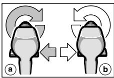
The rotational direction switch 5 is used to reverse the rotational direction of the machine. However, this is not possible with the On/Off switch 4 actuated.
Right Rotation (a)
Turn the rotational direction switch through to the left stop (normal operation: drilling, screwdriving, etc.).
Left Rotation (b)
Press the rotational direction switch through to the right stop (for loosening and unscrewing screws and nuts).
Setting the Torque
With the correct setting, the clutch disengages as soon as the screw is driven flush into the material or the set torque is reached. Select a higher setting when driving out screws, or set to the "Drilling" symbol.
1
Low setting, e. g., small screws, soft materials.
25
High setting, e. g., large screws, hard materials.
Drilling
Set the torque setting ring 2 to the "Drilling" symbol.
Cordless Screwdriver Display
The display 10 is activated when the battery 7 is inserted.
After a while the display switches to the stand-by mode. The display 10 can be activated again by inserting the battery 7 or by pressing one of the two push-button keys on the display.
For temperatures below 0^ the function of the display is limited.
Warning Indicators (see figure E)
The function of the warning indicators is also operative in stand-by mode.
1 The battery is almost empty:
Recharge the battery.
The motor is starting to overheat:
Switch the machine off and allow to cool down. Alternatively, run the machine at full speed without load until the warning indicator goes out.
Adjustment Aid
The display is for guidance. The settings are to be checked by carrying out a practical test.
Material Selection (see figure F)
Select the material to be worked by (multiple) pressing of the left push-button key:
Steel
4 Softwood
Hardwood
Shown in the example: Hardwood.
Application Selection (see figure G)
Select the application by (multiple) pressing of the right push-button key:
6 + 6 Driving in screws (4 Diameter ranges)
7+8Drilling holes (2 Diameter ranges)
Recommendation (see figure H)
The indication gives a recommendation for the optimum setting of your cordless screwdriver. Adjust the proposed values on your cordless screwdriver.
9 1st gear/2nd gear
10 Torque range (Level 1-5, 5-15, 15-25, "Drilling")
Shown in the example: 2nd gear; Torque range 5-15.

Replacing the Drill Chuck
Before any work on the machine itself, remove the battery.
The locking screw 13 secures the drill chuck against loosening from the drill spindle. Fully open the drill chuck and completely unscrew the locking screw 13 by turning in clockwise direction (see figure B).
Loosening the Drill Chuck (see figure C)
Place the machine on a stable surface (e.g. workbench). Hold the machine firmly and loosen the chuck by turning to the left, as when unscrewing a screw (0). Loosen a tight chuck by giving the long end of the Allen key 14 a sharp blow.
Tightening the Drill Chuck (see figure D)
The drill chuck is mounted in reverse order (2).
Operating Instructions
Soft grip
The gripping surface 9 on the rear of the handle (soft grip) reduces the danger of slipping and thereby improves the grip on the machine and the handling.
At the same time, the rubber coating achieves a vibration-reducing effect.
Tips
Use only screwdriver bits that fit properly in the head of the screw.
- When driving in larger and/or longer screws in hard material, it is advisable to drill a pilot hole first.
For drilling in metal, use only perfectly sharpened HSS drills. The appropriate quality is guaranteed by the Bosch accessories program.
Maintenance and Cleaning
Before any work on the machine itself, remove the battery.
For safe and proper working, always keep the machine and the ventilation slots clean.
If the machine should fail despite the care taken in manufacturing and testing procedures, repair should be carried out by an after-sales service centre for Bosch power tools.
In all correspondence and spare parts orders, please always include the 10-digit order number given on the nameplate of the machine.
Environmental Protection

Recycle raw materials instead of disposing as waste
The machine, accessories and packaging should be sorted for environmental-friendly recycling.
These instructions are printed on recycled paper manufactured without chlorine.
The plastic components are labelled for categorized recycling.
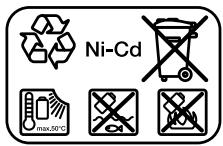
Nickel-cadmium-battery: If your product is equipped with a nickel-cadmium-battery, the battery must be collected, recycled or disposed of in an environmentally-friendly way.
Defective or worn out batteries must be recycled according to the guidelines 91/157/EEC.
Batteries no longer suitable for use can be directly returned at:
Great Britain
Robert Bosch Ltd. (B.S.C.)
P.O.Box 98
Broadwater Park
North Orbital Road
Denham-Uxbridge
Middlesex UB 95HJ
Service +44 (0) 18 95 / 83 87 82
Advice line +44 (0) 18 95 / 83 87 91
Fax. +44 (0) 18 95 / 83 87 89

Noise/Vibration Information
Measured values determined according to EN 50 260.
Typically the A-weighted sound pressure level of the product is less than 70 dB (A).
The noise level when working can exceed 85 dB (A).
Wear hearing protection!
The typical hand/arm vibration is below 2.5m / s^2
Service and Customer Assistance
Exploded views and information on spare parts can be found under:
www.bosch-pt.com
Great Britain
Robert Bosch Ltd. (B.S.C.)
P.O.Box 98
Broadwater Park
North Orbital Road
Denham-Uxbridge
MIDDLEX UB 95HJ
Service +44 (0) 18 95 / 83 87 82
Advice line +44 (0) 18 95 / 83 87 91
Fax. +44 (0) 18 95 / 83 87 89
Ireland
Beaver Distribution Ltd.
Greenhills Road
Tallaght-Dublin 24
Service +353 (0)1 / 414 9400
Fax. +353 (0)1 / 459 8030
Australia
Robert Bosch Australia Ltd.
RBAU/SPT2
1555 Centre Road
P.O. Box 66 Clayton
3168 Clayton/Victoria
+61 (0)1 / 800 804 777
Fax. +61 (0)1 / 800 819 520
www.bosch.com.au
E-Mail: CustomerSupportSPT@au.bosch.com
New Zealand
Robert Bosch Limited
14-16 Constellation Drive
Mairangi Bay
Auckland
New Zealand
C∈ Declaration of Conformity
We declare under our sole responsibility that this product is in conformity with the following standards or standardization documents. EN 50 260 (Battery powered products) and EN 60 335 (Battery charger) according to the provisions of the directives 73/23/EEC, 89/336/EEC, 98/37/EC.
CC03
Dr. Egbert Schneider
Senior Vice President
Engineering
Dr. Eckerhard Strötgen
Head of Product
Certification


Subject to change without notice

\section*{Caracteristiques techniques}
Robert Bosch France S.A.
ServiceAprès-vente/Outillage
Senior Vice President
Engineering
Dr. Eckerhard Strötgen
Head of Product
Certification
paa / 1000 i.v. nuogcu
Senior Vice President
Engineering
Dr. Eckerhard Strötgen
Head of Product
Certification


Senior Vice President
Engineering
Dr. Eckerhard Strötgen
Head of Product
Certification


Senior Vice President
Engineering
Dr. Eckerhard Strötgen
Head of Product
Certification

Senior Vice President
Engineering
Dr. Eckerhard Strötgen
Head of Product
Certification


Eksemplet viser:Hardt tree.
Nikkel-cadmium-akku:
Senior Vice President
Engineering
Dr. Eckerhard Strötgen
Head of Product
Certification


Senior Vice President Engineering
Dr. Eckerhard Strötgen
Head of Product Certification


Turtalls-innstilling
Ved riktig innstilling utloses slurekoblingen sasnart skruen er skrudd plant inn i materialet hvh. det innstilte dreiemomentet er nadd. Velg en hoyere innstilling ved utskruing, hhv. innstill pa symbolet «Boring».
1
Svak innstilling, f. eks. sma skruer, myke materialer.
25
Sterk innstilling, f.eks. store skruer, harde materialer.
Boring

Sett dreiemoment-innstellingsringen 2
pá symbolet «Boring».
Akku-skrutrekker display
Displayet 10 aktiveres nár batteriet 7 settes inn.
Senior Vice President
Engineering
Dr. Eckerhard Strötgen
Head of Product
Certification


Senior Vice President
Engineering
Dr. Eckerhard Strötgen
Head of Product
Certification


Biodu (BLeNε Eikova A)
Dr. Egbert Schneider Senior Vice President Engineering
Dr. Eckerhard Strötgen
Head of Product Certification


Bosch San. ve Tic. A.S.
Ahi Evran Cad. No:1 Kat:22
Polaris Plaza
80670 Maslak/Istanbul
+90 (0)212 / 335 06 00
Faks. +90 (0)212 / 346 00 48-49
C∈Uygunluk beyani
Senior Vice President
Engineering
Dr. Eckerhard Strötgen
Head of Product
Certification