BLM1001 - Metal Lathe Ferm - Free user manual and instructions
Find the device manual for free BLM1001 Ferm in PDF.


| Product type | Metal lathe |
| Brand | Ferm |
| Model | BLM1001 |
| Height of centers | 110 mm |
| Distance between centers | 350 mm |
| Swing over bed | 200 mm |
| Swing over cross slide | 115 mm |
| Spindle bore | 18 mm, Morse taper MT-3 |
| Spindle speeds | 6 speeds, 120-2000 rpm |
| Threading possible | Pitch from 0.4 to 3 mm (11 different threads) |
| Automatic feed | Yes, by combined leadscrew |
| Motor | 230 V, 50 Hz, 375 W, single-phase |
| Weight | 110 kg |
| Bed material | Grey cast iron with prismatic guides |
| Lubrication | Oil bath for headstock, regular lubrication of slides |
| Safety | Emergency stop, eye protection required, protective cover |
| Maintenance | Chip cleaning, oiling, play elimination according to table |
| Spare parts available | Yes, gear wheels, belts, nuts, etc. |
| Warranty | According to the provided warranty certificate |
Frequently Asked Questions - BLM1001 Ferm
User questions about BLM1001 Ferm
0 question about this device. Answer the ones you know or ask your own.
Ask a new question about this device
Download the instructions for your Metal Lathe in PDF format for free! Find your manual BLM1001 - Ferm and take your electronic device back in hand. On this page are published all the documents necessary for the use of your device. BLM1001 by Ferm.
USER MANUAL BLM1001 Ferm
Carefully read this manual before using the machine. Make sure that you know how the machine functions and how to operate it. Maintain the machine in accordance with the instructions to make sure it functions properly. Keep this manual and the enclosed documentation with the machine.
USE
The metal lathe has been designed for processing, mechanically removing metal, of ferrous and non-ferrous metals, synthetics and wood. The metal lathe is meant for semi-professional use and for leisure interests.
SAFETY INSTRUCTIONS
When using electric machines always observe the safety regulations applicable in your country to reduce the risk of fire, electric shock and personal injury. Read the following safety instructions and also the enclosed safety instructions.
Keep these instructions in a safe place!
At the design of the machine is made allowance for the requirements for a safe use. Every change, adaptation, reconstruction or other adaptation use can cancel the safety of the object. Besides the guarantee will expire through this.
Before, after and during working with the lathe a number of safety rules have to be taken. By the presence of turning parts and sharp objects very severe injury can arise. Especially the bits of the turning chuck are very dangerous.
-
The lathe has been designed for manufacturing unruly material and so it has to be able to develop a lot of power. That is why touching turning parts is perilous. For this reason unlawfully, undesirably or unintentionally switching on the machine has to be prevented, for example by the pushed in locking of the emergency stop valve by means of a small padlock.
-
By the elastic working of the chisel metal parts can be shoot away with a big power at the most unexpected moments.
- Protection of the eyes is very important. Make it a habit to wear special safety glasses when you are in the space where the lathe stands. Buy yourself a professional and tested copy which you can wear for a long time and if need be for visitors a cheaper one, but this one also has to be a good performance.
- If you take care of a cheerful workshop you can prevent
for example gripping in the machine or falling by stumbling over flinging about material.
- Be very careful when you make turning pieces of work with the hands.
- When you want to polish a surface turning, then take a long piece of polish paper which you can place half around the piece of work, with the ends to your direction.
- Never turn the ends around the fingers, never push sand-paper on the piece of work with your hands.
- By turning, edges of the piece of work exist which are sharp as a razor. These edges have to be smoothed off with a file or a trimming hook.
-
Never remove chipcurls with your hands Use a little hook which has been made by yourself of thread or buy a professional chips hook.
-
Never grip over the turning machine or chuck when during turning something falls in or behind the bed.
Always first stop the machine. See that the covering plate lies on the opening in the bed.
- A good lighting prevents that you operate the machine from too close by.
- If you apply strip light you have to make allowance for the so-called strobosto scopic effect. Through this a turning object seems to stand still. A solution is the use of double armatures by which a phase shifting of the two strip lights has been accomplished.
7. Emergency stop
If a dangerous situation arises unexpectedly, for example if a badly exerted piece of work seems to get loose during turning, you van use the emergency stop by giving a tap on the yellow cover of the safety switch, marked 'STOP'. The machine now stops without pushing in the switch button yourself.
SPARE PARTS FOR MD-350/MD-500
REF. NR. DESCRIPTION FERM NR.
| 0.01 Shears 400311 | |
| 0.02 Intermediate gear spindle | 400312 |
| 1.01 Locking handle | 400300 |
| 1.03 Clamping nut | 400301 |
| 1.05 Spindle | 400302 |
| 1.06 Spindle bearing | 400303 |
| 1.07 Handwheel for support | 400304 |
| 1.08 Cover plate | 400305 |
| 1.09 Spindle nut | 400306 |
| 1.10 Tail stock | 400307 |
| 1.11 Pinole MT-2 | 400308 |
| 1.12 Baseplate / bedplate | 400309 |
| 1.13 Locking bolt | 400310 |
| 2.02 Press handle | 400313 |
| 2.03 Holder complete | 400314 |
| 2.04 Axle pin tool holder | 400315 |
| 2.05 Tool support (top) | 400316 |
| 2.06 Sunk key | 400317 |
| 2.09 Spindle | 400318 |
| 2.14 Handle 400319 | |
| 2.16 Nut (tool slide) | 400320 |
| 2.17 Tool slide (under) | 400321 |
| 2.18 Locking bolt | 400322 |
| 2.20 Turning pin | 400323 |
| 2.21 Key cross slide | 400324 |
| 3.01 Handle 400325 | |
| 3.04 Spindle | 400326 |
| 3.05 Spindle nut | 400327 |
| 3.10 Baseplate cross slide | 400328 |
| 3.11 Hollow key | 400329 |
| 3.13 Longitudinal direction spindle | 400330 |
| 3.15 Hand wheel | 400331 |
| 3.17 Half nut lever | 400332 |
| 3.18 Half nut mechanism | 400333 |
| 3.21 Longitudinal direction spindle (internal) | 400334 |
| 3.22 Bearing | 400335 |
| 4.03 Motor | 400336 |
| 4.04 Motor pulley | 400337 |
| 4.07 Headstock with cover | 400338 |
| 4.08 Main spindle | 400339 |
| 4.10 Main spindle pulley | 400340 |
| 4.11 Intermediate pulley | 400341 |
| 4.12 Tension roller | 400342 |
| 4.16 Switch | 400343 |
| 4.17 Bearing (lead screw) | 400344 |
| 4.23 Thrust bearing | 400345 |
| 4.24 Rack MD-350 | 400346 |
| 4.24 Rack MD-500 | 400367 |
| 4.24 Rack | 400368 |
| 5.01 Gear 51 | 400347 |
| 5.02 Gear 68 | 400348 |
| 5.03 Gear 25 | 400349 |
| 5.04 Gear 75 | 400350 |
| 5.05 Gear 76 | 400351 |
| 5.06 Gear 24 | 400352 |
| 5.07 Gear 24 | 400353 |
| 5.08 Gear 76 | 400354 |
| 5.09 Gear 56 | 400355 |
| 5.10 Gear 56 | 400356 |
| 5.11 Change wheel 30 | 400357 |
| 5.12 Change wheel 42 | 400358 |
| 5.13 Change wheel 49 | 400359 |
| 5.14 Change wheel 28 | 400360 |
| 5.15 Change wheel 63 | 400361 |
| 5.16 Change wheel 70 | 400362 |
| 5.17 Change wheel 84 | 400363 |
| 5.18 Change wheel 98 | 400364 |
| 5.19 Change wheel 105 | 400365 |
| - Center MC-3 | 400368 |
| - Center MC-2 | 400369 |
| - 3-Jaw chuck | 400370 |
| - 4-Jaw chuck | 400371 |
| - V-belt tension roller | 400372 |
| - Micr switch for door | 400373 |
| - V-Belt Z31 (10 x 790) | 800114 |
| - V-Belt Z28 (10 x 710) | 800170 |
| - V-Belt Z35 (10 x 890) | 800197 |
- The reference numbers refer to the 5 annexes indicated with the numbers 0, 1, 2, 3, 4, 5. The number in front of the point refers to the Annex, the number behind the point refers to the part. So, reference 4.07 refers to Annex 4, part 7
natural_image
Close-up of mechanical pulley and gears assembly (no visible text or symbols)V-Belt / Riemen / V-Snaar / Courroles t rapézoïdales

natural_image
Mechanical assembly with rotating components and mounting holes (no visible text or symbols)Bottom side Support/Unterseite Support / Onderzijde support / Surface inférieure de support

natural_image
Industrial machine setup with levers and control panel (no visible text or symbols)The Support|Das Support | Het support | Le support

natural_image
Cross-sectional view of a mechanical assembly with internal components (no visible text or symbols)Oil bath in gearbox!Ölbad im Zahnräderkasten Oliebad in de tandwielkast! Bain d'huile de boite d'en-grenage

natural_image
Exterior view of a vintage metalworking lathe machine (no visible text or labels)Floor Stand | Unterschrank | Onderstel | Bas de casse. Art.nr.: 330957

natural_image
Collection of industrial clamping devices including a mechanical clamp, pulley, and tools (no visible text or labels)Accessories/Unterteile | Onderdelen | Accessoires
TECHNICAL SPECIFICATIONS
| Mains voltage 230 VoltMains frequency 50 HzAbsorbed power 375 WattCenter height 110 mmCenter distance MD-350 350 mmCenter distance MD-500 500 mmMax. turndiameter above bed 200 mmMax. turndiameter above support 115 mmCulvert and recording main shaft 18 mm, MT-3Number of speeds main shaft: 6No load speeds main shaft 120-2,000/min.Automatic start: 11 mm; 0,04 - 0,3Thread cutting (right) 11 mm; M0.4 - M3Distance toolholder centerline -measured vertically 15 mm | |
| Rotating plate movement:Graduation rotating plate: | 3600± 450 |
| Movement tool cut | 70 mm |
| Movement cross slide | 115 mm |
| Movement end slide | 350 mm |
| Graduation slide screws | 0,04 mm |
| Recording and stroke slide tube | 50 mm; MT-2 |
| Graduation slide tube | 0,05 mm |
| Weight MD-350 | 110 kg |
| Weight MD-500 130 kg. | |
| Sound pressure lva | 70 dB(A) |
| Vibration value | 2.8 m/s |
THE MD-350 AND THE MD-500 ARE DELIVERED IN THE FOLLOWING BASE PERFORMANCE.
Machinebed with prism conductor, ferme head with main shaft and drive for automatic longitudinal feed and thread cutting, tail stock with sliding tube and transverse adjustment, electro motor with start/stop- and sense of rotation switch, support with lock case, combined with starting/lead screw, cross slide with rotating plate and tool slide, fourfold tool holder with index pin, 3-chuck with extra exterior basins and measuring certificate, drive protection case, 7 change wheels, 3 driving-belts, 2 centers, 3 open-end spanners, 2 socket head wrenches, catch pin and a tightening-wrench chuck.
Excluded under-carriage (art. nr.330957).
INSTALLATION
SPACE.
Next to a good maintenance it is very important the machine is installed dirily, as the machine has been built up for the biggest part of metal. Spaces can become moist by insufficient or a wrong ventilation, burning not regularly or by raced walls and lifting moisture. Condensation of moisture on the metals caused by suddenly raising the temperature in a cold space. See that the temperature is equable.
UNPACKING AND INSTALLING
The machine is packed in a strong case which you can dismantle to six flat parts which can be put away easily. These parts can be saved in case you have to transport the lathe, for example for repairor for a removal. After you have opened the case the lathe has to be detached from the pallet. For this you have to remove two nuts, in each bedfoot one. Later the nuts can be used again. For lifting up the lathe you may call in the help of an assistant, this depends on the weight. Before you begin you have to arrange how to lift the machine. You should rather put the machine from the pallet on the permanent destination at one go. The best thing is grip the machine at the ends of the bed, so do not grip it on the heads, transporter, change wheel case or motor! The apparatus weights roughly 110 kg. For reducing the weight temporary a number of parts can be removed carefully, like the tail stock, the turning plate with building and the discs from iron cast. The lathe has to be level and it has to be installed on a strong bottom. If you make an under-carriage yourself you can use a steel U-profile of sufficient lenght, on which you can sold or screw a leg construction. You can also use a strong wooden lower case with a strengthened and flat upper blade, for example by means of a piece of multiple worktop. The condition is that the formation has to be stiff in every directions and that it cannot fling about, bend or wobble. The lathe is fixed with two bolts M10 in the special gaps in both bottom plates.
TIP: You can take the following precautionary measures for preventing that small roughnesses still cause tension on the bed if you tighten the two bolts. You draw the place of the two bottom plates and the two assembling gaps and you assemble two bolts M10 in the foundation. Put on the drawn places a layer epoxy filling. Install a plastic foil on this. See that the bolts stay clear! Then install the workbench on the drawn place. Use the two bolts for this as the conductor. Let down the bed on the foil and then harden the filling. After that you can provide the bolts with the nuts which are also used for the transport, and then you can tighten these ones again.
ELECTRICAL CONNECTION
After the motor has been installed permanently a connection to the electrical installation has to be made. The machine has been made for use on the existing 230 Volts alternating current mains and hasn't a power bigger than other big household equipment with a motor. Have an eart-
hed power point installed in the nearness of the machine and see that the lead can be guided to the contact without cracks and pulls. If need be an earthed extension cable can be used, but see that the cable is unrolled entirely and that it is not in the way.
ELECTRICAL SAFETY
Always check that the power supply corresponds to the voltage on the rating plate.
REPLACING CABLES OR PLUGS
Immediately throw away old cables or plugs when they have been replaced by new ones. It is dangerous to insert the plug of a loose cable in the wall outlet.
BEFORE OPERATION
For transport the machine has been greased with a layer which prevents rust. This layer has no greasing function and has to be removed with clothes. You can do this with a solvent which is not aggressive, for example turpentine or petroleum. When you are acquainted with metal-working machines you can dismantle, control and oil several spare parts with a light and universal machine-oil, for example sewing-machine oil (sour free). Afterwards you finish the complete maintenance table of chapter 14 'maintenance'.
ADJUSTMENT
| SPARE PART | LIFTING A MARGIN | RECOURS |
| Spindle tool slide | Loosen the front lock nut, distort the back lock nut clockwise, until margin is minimum, turn back a fourth part and tighten the front lock nut | 2 hook spanners |
| Tool slide | Loosen the lock nuts, tightening the adjusting nuts clockwise until margin is minimum. tighten lock nuts | screw-driver, open end wrench |
| Spindle cross slide | Watch spindle tool support | idem |
| Cross slide | Watch tool slide idem | idem |
| Transmission/ starting shaft | Loosen front lock nut and tighten hindmost lock nut until margin is no longer noticeable, turn back a quarter part and tighten the front lock nut | idem |
| Tailstock | Loosen clamping nut, unscrew both adjusting nuts on both sides a quarter part.Move head with adjusting screws until the mark signs on the right side of the head correspond, tighten the adjusting screws again a bit without moving the head, fixing the clamping nut. | screw-driver, open end wrench |
The lathe has been adjusted to a minimum margin by the factory. Because of transport some adjustments can be changed. On the other hand the machine has been designed in such a way that any appearing margin can be lifted. This margin is also caused by wear end tear as a consequence of an intensif use. If re-adjustment does not have an effect anymore, the part is worn and has to be moved.

natural_image
Technical line drawing of mechanical components with no visible text or symbols





natural_image
Technical line drawing of two mechanical components with pulleys and gears (no text or symbols)If all preparations have been done the machine can be connected to the mains by putting the plug into the power point. Beforehand check if the mains switch is "OFF" and check if the turning directions is "RIGHT". Watch the gauge once more and see if the oil level has not changed and necessary you have to fill it till the gauge half-full. See that there is no paper or cleaning-rag for the ventilation on openings of the motor. Check the three-jaw and see that the basins cannot come out of the jaw.
PUT THE JAW-WRENCH ON A PERMANENT PLACE! Open the protection case and check the position and tension of the belts. For running on trial the lowest turning speed has to be chosen. You may shift the front belt, watch fig.5 and 15. Push in the switch and have the machine turned during 20 minutes. Check regularly if the head bearings in the headstock and the motor do not become hot by stopping the machine and putting a hand on both side of the headstock and on the motor body. Immediately stop if you hear a deviating noise and if you feel an abnormal health development (more than handwam) and first contact your supplier. Then switch over to a higher speed and have the machine also function a few minutes on this speed. Do this again with a reversed turning direction. If no problems have arisen, the machine is ready for use.
WORKING METHOD
Removing metal takes place by pushing under control a chisel point or a boring point in the piece of work through which small pieces of material - chips - are cut away. For this the piece of work has to make a turning movement between two fixed turning points- the headstock and the tail stock (watch fig.1) - which lie on a very precise, imaginary line: the centerline(4). This can be turned off parallelly to the centerline over the whole length, by carrying the chisel which has been fixed on the support(5) in a certain tempo along the turning piece of work. This has to be done in a straight line, with the hands or automatically with the transmission(6). For removing material of the piece of work, power is needed. This power is transmitted from the motor to an empty shaft in the headstock: the main shaft (2). In connection with the maximum motorcapacity the quantity material which has to be taken - the chip thickness and the width of chip- has to be adapted. If the number of revolutions lowers too much, the starting depth or the rate of speed has to be lowered. Otherwise there is a chance of motor damage, shorter tool life of the chisel or the chisel rupture. The diameter of the piece of work is also influences this. If you have a diameter of 100 mm more power is needed for cutting a chip of 1 mm than at a diameter of 10 mm. When the tail stock (8) is placed next to the centerline because of cross adjustment, an outward conical plane is turned. An extra processing possibility over the length axle is cutting a screw-thread. A special chisel cuts a spiral deepening in the outline of the piece of work. A part of the out
line keeps on standing and this height difference forms the ultimate screw-thread. Next to turning over the lenght axle, the ends of a piece of work can also be processed, for example for making them flat and straight. Short pieces of work can be fixed at one side in a fixed turning-point, the three-jaw chuck, and on the other side be processed at right angles to the centerline. The basins of the chuck see to maintenance of an imaginary centerline. By having occurred the chisel replace ment under an angle by adjustment of the chuck, inward and outward conical planes can be turned. With this strain borings can also be made in levelled surfaces. For that a drill chuck has to be bought separately. This drill chuck with morse cone peg has to be installed in the sliding tube (7) of the tail stock. Then the gaps can be screen out until the desired dept, diameter and form.
IMPORTANT: The precision of the pieces of work is first and particularly depend dant of expertiness and experience. During turning many factors can influence the end result, like the sort and the condition of the chisels, the nature of the material you want to process, the turn and starting speed, the fixation of the piece of work, the drafting and the condition of the machine. With the MD-350 it is possible to manufacture prolonged pieces of work with a big accuracy, if all circumstances are perfect.
FOR THE BEGINNING TURNER.
During turning big powers on certain parts can be developed. If you use the machine incorrect these parts can be damaged or deformed and wear end tear faster, even if they have been made and designed very expertly and carefully. Through this the accuracy of the machine will decrease strongly, which directly influences the quality and take precision of your pieces of work. So it is important that the apparatus is tended in an expert way. Recommended is, if you are not a skilled turner, to start with simple pieces of work and to try the different possibilities of the lathe with trial pieces of work. It is instructive to look at skilled turners, because you are not that fast a perfect turner! For pre venting disappointments you have to become familiar with the basic principles of turning. Turning is not for nothing a profession. You can find referencebooks about metal working and metal turning in the library or in a book-shop. Besides model-building magazines write about this subject regularly. The best is getting into possession of a, if need be obsolete, technical text-book. In this book is told about the general principles of turning and many things worth knowing and handy summaries of problems with possible causes and solutions.
FUNCTION OF THE MACHINE.
For a good understanding of the working of the machine this one can for convenience sake be divided in a number of main groups and components, all with a special function. Watch fig.1.
THE MACHINE BED
The machine bed connects all these parts and has next to it also other important functions. The bed (3) has been manufactured of highgrade grey cast iron and it is provided with several filled cross ties. Because of the design and the applied sorts of material tremblings are better absorbed and deforming because of charge is minimum. The bed is provided with two sliding surfaces sharpened very precisely, for the conducting of support and tail stock. These conductings, one prismatic and one flat, see to maintenance of the centerline(4):watch fig.2.
THE MOTOR
The attached alternating current motor is a carbon brushless 1-phase squirrel-cage motor with startling condenser. The motor is maintenancefree and does not need a special treatment. By means of V-belts and plural belt discs, the pulleys, the movement of the motor is transmitted to the mains axis.
THE HEADSTOCK
The poured headstock(1) has been fixed on the bod with a prism conducting and two face plates. On the back side is an oil draining nut. The cover is remo vable for inspection and for putting oil. At the bottom of the head you can find a system of turning axis and toothed wheels. Because of these toothed wheels the speed of the main shaft is retarded and transmitted to a double, coaxial output axis. On this axis you can find the driving gear for the start and the driving gear for the thread-cutting, watch fig.3. In the head you can find the most important part of the machine, the main shaft(2).
This one has been fixed revolving with two conical roller bearings in an O- drafting. All turning parts in the head are lubricated by means of an oil bath. The level of this is readable in the window on the front side. The main shaft has been provided with a going on boring with on the right side a fixing flange and a morse cone, for respectively the chucks and the center.
THE SUPPORT
On the sliding surfaces on the bed the support(5) has been fixed which sees that conducting tools along the piece of work is checked. First the support consists of a bed slide with lock case. This slide lies on the bed and serves as movement in the length direction. This movement can occur with the hands or automatically by the transmission/feeding axis(6). In the last case the coach bolt has to be closed in the lock case. On the bed slide a second slide has been installed which takes care of the chisel movement in cross direction. By means of a spindle with follow nut this slide can be moved or adjusted. On the cross slide a chuck has been installed. With this the upper slide or tool slide can be adjusted under an angle. The third and upper slide, tool slide, can be replaced in any desired direction over a distance of 70 mm and it follows every movement of all underlying slides also the chuck. On top of the tool slide a tool holder has been installed. In this tool can be exerted to a point height of maximum 15 mm, the vertical distance to the centerline. The tool holder has a fourfold absorption and has an indexing pin with four click points. Through this can be changed of chisel very fast without having to adjust again.
THE TAIL STOCK
The end of the centerline is formed by the tail stock (8). The axis of the fixed and tail stock are exactly in each others extension. Depending on the length of the piece of work the head can be moved over the bed and it can be fixed. With the slide bush (7), in which a center has to be installed, the piece of work can be exerted fixed and revolving right on the centerline. If you turn back the slide bush, the center is automatically untied. The body of the head has been divided. The upper part can be adjusted sideways with regard to the upper part by means of adjusting screws. Through this an adjustment next to the centerline can be obtained. Normal movements in the length direction do not have side ways adjustments as a consequence.
THE COMBINED TRANSMISSION/STARTING AXLE
For a good surface quality a correct and particularly a constant rate of turnover in the longitudinal direction is important. For longer pieces of work this is almost impossible with your hands. By closing the lock nut the support is coupled with the thread on the transmission. When the transmission has been switched on this one has been coupled to the main shaft in his turn. With this a coupling is made with an intermediate wheel between the drive wheel of the transmission and the drive wheel for the longitudinal feed on the headstock. This happens because of an adjustment of the change wheel scissors, watch fig. 3 and 4. At each rotation of the main shaft the support will move itself over a certain distance along the bed. This distance depends on the wire haste and the chosen wheel change on the transmission. By chasing another wheel change the starting speed can be adapted.
With thread-cutting the same happens in principle, however with a much bigger support movement with a much lower main shaft speed. In this case a coupling has to be made with the thread-cutting driving gear of the headstock. The positioning of the gear wheels happens by the installation of the rings on the starting axle and intermediate wheel axle of the scissors. In this case change of the change wheel on the transmission makes possible a choice of the haste of the thread which has to be cut. On the transmission is no automatic cut out. So switch this one off for preventing that the chisel runs against the chuck.
THE DRIVE
Since the applied motor has a fixed and relatively high number of revolutions the transmission has been done in such a way that this reduces the numbers of revolutions at the same time. Besides, with the application of plural pulleys and an intermediate pulley this number of revolutions is variable in six successive steps.
For lifting up possible belt tension differences the bearing-mounted belt pressure roll has been made variable. Watch fig.5. For reaching the three highest spindle


natural_image
Technical line drawing of a structural steel beam (no text or symbols)
natural_image
Pure mechanical assembly diagram without any text, numbers, or symbols
natural_image
Technical line drawing of a mechanical assembly with no visible text or symbols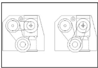
natural_image
Technical line drawing of two mechanical components with pulleys and mounting holes (no text or symbols)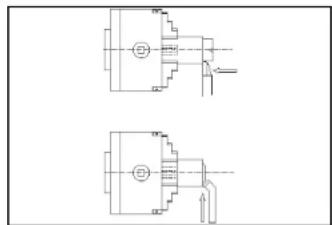
natural_image
Pure mechanical component diagrams without any text, numbers, or symbols
natural_image
Technical line drawing of two mechanical components with mounting holes and shafts (no text or symbols)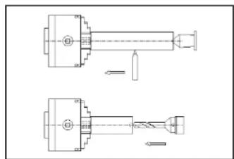
natural_image
Technical line drawing of two mechanical components with no visible text or symbols5
TANDWIEL-, SPINDEL- EN VOLGMOERGEGEVENS
ROUE DENTÉE, BROCHE ET DONNÉES D'ÉCROUS D'ORDRE
speeds the front belt has to be shifted from the intermediate-pulley to the motor pulley. The intermediate gear keeps driven and serves as flywheel for catching load variations.
BASIC PRINCIPLES OF THE TURNING
Before you can start turning, you have to know the most important basic under standings. Otherwise there is a change that the wrong turning speed or the wrong chisel is chosen. With a number of tables and rules making the machine ready for turning is easier.
CLAMPING
Clamping the piece of work has to happen with care. Put the piece of work in the chuck as far as possible and clamp this one with the tightening wrench. If you clamp too hard the chuck, basins or the piece of work can be damaged. The same applies for the sliding tube. Tighten this one with your hands, strong but not by force. Some clamping examples by which also the use of bores and chisel is made clear, can be seen in fig.6, 7 and 8.
The represented standard three-chuck is self-centring. Through this the axis of a small piece of work falls exactly on the centerline, even if the dead centre is not used. With a chuck belongs an inside basin (represented) and an outside basin. These ones are used for inside clamping of bigger diameters. Every basin has in the chuck the same place. Place and basin are numbered!
In fig.6 a right side cutting chisel (up) and a right bended roughing tool is used. The arrows indicate the starting direction. The roughing tool can be used in longitudinal direction and in cross direction and is often used for quickly eliminating many material. Fig.7 shows the use of a left side cutting chisel and a blind boring chisel. Fig.8 shows a clamp with dead center in a tail stock. A pointed chisel has been used for an egal finish. Under this figure a clamping is represented for making a bore with a spiral drill. Before-hand you have to pre-drill with a center bore. This is a bore from which the shank is much thicker than the crossing frog. The boring gap which arises through that serves as a center gap for both the center and the bore!
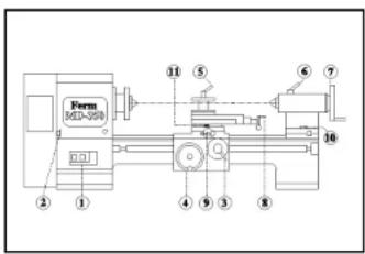
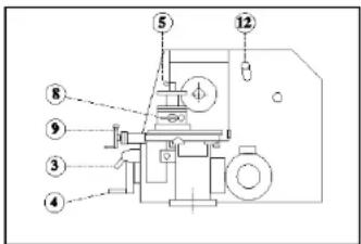
Survey of the operation points with corresponding function (see fig.9,10 11 and 12).
1 Combined on/of direction of rotation switch with emergency feature blocked.
Switching on the motor and chancing the direction of stop rotation, the valve can be blocked with a lock.
2. Drive cupboard closing
For opening and closing of the case
3. Carriage nut handle
By closing the carriage nut, the automatic starting is switched on.
4. Handwheel longitudinal adjustment
For quickly moving the support to the left and to the right. On the nonius can be written how big the adjustment is in steps of 0.04 mm.
5. Clamping handle tool holder
By unloading the handle the bit block can be turned in steps of 90°
6. Clamping handle sliding bush.
For fixing the sliding bush
7. Handwheel sliding bush
By turning the piece of work can be clamped between the chuck and the center; also used for boring; on the nonius can be written how big the adjustment is in steps of 0.05 mm.
8. Handwheel crank tool slide
for the longitudinal adjustment of the tool slide; on the nonius can be written how big the adjustment is in steps of 0.04 mm.
9. Handwheel crank cross slide
for the longitudinal adjustment of the cross slide; on the nonius can be written how big the adjustment is in steps of 0.04 mm.
10 Clamping nut tail stock
for clamping the tail stock to the bed; for clamping the upper part to the bottomplate.
11 Clamping nuts rotary plate
After the desired corner has been adjusted the rotary plate parts can be clamped on each other with this.
12 V-belt tension roller
Makes it possible to change V-belts, to clamp and shift them without dismantling the pulleys.
13 Main shaft pulley
Adjusting rotary speed.
14 Intermediate pulley
Adjusting rotary speed.
15 Motor pulley
Adjusting rotary speed.
16 Scissor
for assembling an intermediate change wheel and being able to adjust this in three directions. Coupling transmission
17 Clamping bolt link adjustment
By adapting the position of the quadrant the intermediate drive wheel and the transmission change wheel
can be placed. Switching the transmission on and off.
18 Intermediate change wheel
Direction of rotation transmission; adjusting the transmission ratio
19 Chance wheel transmission.
Adjusting transmission ratio; by means of placing filling rings the wheel can be adjusted in axial direction(fig.3)
Longitudinal motion support
20 Transmission/lead screw
fixation intermediate change wheel; by means of installing the filling rings he wheel is axial adjustable and with the lowest shaft nut the wheel is adjustable sideways
21 Intermediate change wheel.
In front of the thread-cutting wheel, behind the starting wheel
22 Drive gear wheels for start.
by using this clamping device for surfacing and thread-cutting the lock nut can stay open and the support does not slip away; spindle and nut are less charged then.
23 Clamping bolt cross slide.
CHISELS
During turning a chip is cut out of the piece of work. For this chisels have to be sharpened in a special and sharp form. This form depends on the chisel material and on the material you want to cut. Watch the next table.
| Chisel corners | Light cut | Normal cut | Heavy cut | |||
| HSS | HM | HSS | HM | H$ | HM | |
| cutting-edge side rake | 12 | 10 | 10 | 5 | 5 | 0 |
| Clearance angle | 8 | 6 | 7 | 5 | 6 | 4 |
| Wedge angle | 70 | 74 | 73 | 80 | 79 | 86 |
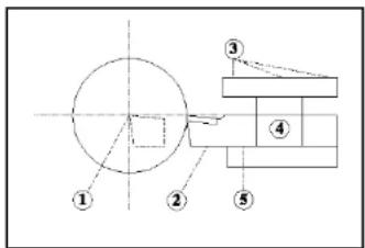
On the basis of fig. 13 the corners of this table can be taken over on a little piece square high-speed steel for making or re-sharpening your own chisel. In this example we are talking about a straight, right roughing tool. The dotted lines indicate the original form of the bar. The sum of the angles 1,2 and 3 is always 90^ . Angle 1 is the cutting-edge side rake, angle 2 the wedge angle and angle three the clearance angle. For keeping the friction as low as possible, two extra clearance angles have been sharpened: angle 4 and angle 6. Besides, a slope angle 5 has been installed. The arrow indicates the starting direction. The front face is called the minor cutting face. The main cutting face is the part on which the arrow has been drawn. In this way all possible chisels can sharpen themselves, by which you have to say where the main cutting face has to be and what the turning material has to be.
A perfectly sharpened chisel has to be placed in the tool holder in the right way now. Fig.14 indicates a correct pla-
ding of a pointed chisel. Point 1 is the center line. The tip of the chisel has to stand exactly that high. If not, you have to use bearing plates(5). The chisel always has to be placed against the block body(4) and cannot extend farther than 1 to 1.5 time the tool shank thickness(2).
It goes without saying that all clamping bolts (3) have to be tightened strongly.
TURNING SPEED
If the chisel have been sharpened and put, the piece of work has been clamped well, the speed of the main shaft has to be adjusted with the V-belts, watch fig. 15 and 16. In the subjoined table some machining speeds which happen many times are indicated for different sorts of chisels and materials.
| Turning material Chissel | Turning speed | |
| material | REV/MIN | |
| Unalloyed structural steel (9S20k - 60S20k) | HSS | 40 - 60 |
| P10 | 140 - 160 | |
| Alloyed structural steel Tool steel (C80= Silversteel) | HSS | 32 |
| P10 | 112 | |
| Cast Iron | HSS | 40 |
| K10 | 100 | |
| Non-Ferrous (Cupper, Aluminium) | HSS | 45 - 80 |
| K10 | 140 - 280 | |
With this table you can chose yourself for any diameter the right speed. The only thing you have to do is fill in the desired speed in the following formula.
v = cutting speed in meters per minute
d = diameter of the piece of work in mm
n = number of revolutions in revolutions per minute
π= constant, nl. 3,14
| v = ¥d ¥n1000 = ¥1000 ¥d |
Calculation example
-
A round piece of silver steel of 100 mm has to be turned with a HSS chisel. You can find in the table that silver steel has to be turned with 32m/min, v=32 Divide 32.000 by 100 gives a number of revolutions of 320 revolutions per minute. We put belt 2 on the hindmost discs of the intermediate and main shaft pulley.
-
A piece of copper of 10 mm is turned with a HM-chisel. v=200 and through that "n" comes far above the maximum number of revolutions. The highest number of revolutions can be adjusted. Belt two is layed on the hindmost disc of the motor and main shaft pulley.
-
Bed
- Motor base plate
- Motor
- Motor pulley
- Guard
- Mounting plate
- Headstock with cover
- Mains spindle
- Bearing cover
- Main spindle pulley
- Idler
- Tension pulley
- Bolts with ring
- Chuck headstock
- Oil cup
- Switch
- Longitudinal
motion bearing - Longitudinal traverse (lathe
spindle - Bearing housing drive shaft
- Drive shaft longitudinal and
transverse motion - Bush
- Castle locking nuts
- Axial thrust bearing
Anlage 4 Bijlage 4 Zubehörverzeichnis: Onderdelenoverzicht - Maschinenbelt
- Motorsstellplatie
- Motor
- Motorriemenscheibe
- Schutzkasten
- Befestigungsplatte
- Spindelstock mit Deckel
- Hauptwelle
- Lagerdecke
- Hauptwellenriemenscheibe
- Zwischenriemenscheibe
- Spannrolle
- Bolzen mil Ring
- Spannplatten Spindelstock
- Ölstopfen
- Schalter
- Fördererlager
- Längsvorschub (Leilspin-
del) - Lagergehäuse Antriebs-
welle - Antriebswelle Fördere
- Kupplungsschale
- Kronensicherungsmuttern
- Axialdrucklager
- Zahnstange
Bijlage 4 Onderdelenoverzicht
1 bed
2 motorsleplaat
2 motor 3 motor
5 motor 4 motomcelie
4 motorpolic 5 bechemmin
6 bevestigingsplaat - vaste kon met del
8 hoofdas
9 lacerdek
10 hoofdasnce
11 lussenppelie
12 spanrol - boulen mal ring
- spanplaten vaste koo
- oliedon
16 schakelaar - transporteur-lager
- lansvoeding (leispindel)
- lagerhuis aandrifas
- aandrifas transporteur
21 koppelbus
22 kroonborgmoeren - aviaal druklager
- tandheugel
24 landncager
Pièce annexe 4 Aperçu pièces détachées: - banc
- plaquette de réglage mo-
lèur - moteur
- poulie de moteur
- boîte de protection
- plaquette de fixation
- poupée fixe avec couvercle
- essieu principa
- couvercle de roulement
- poulie de l'essieu principal
- poulie intermédiaire
- galet de tension
- boulons avec rondelle
- plaques de tensión
poupées fixe - bouchon de vidange d'huile
- commutateur
- roulement de transport
- avance longitudinale (bro-
che de guidage) - arbre d'entraînement de
boîte de roulement - arbre d'entraînement trans-
porteur - douille de connexion
- écrous de blocage à cré-
Annex 4
List of parts
BED/HEADSTOCK
Nr. Part
- Gear rack
MASCHINENBETT/
SPINDELSTOCK
Nr. Zubehörteil
Bed/Vaste kop
Nr.
Onderdeel
Banc/Poupée fixe
N° pièce détachée
Annex 3
Anlage 3
Bijlage 3
Pièce annexe 3
TRAVERSING SLIDE/APRON
Nr. Part
-
Handwheel lever
-
Socket head screww
-
Spindle Bearing
-
Spindle
-
Spindle nut
-
Castle locking nut
-
Vernier
-
Vomier
-
Socket
-
Socket head screws
-
Cross slide base
-
Cross slide base
-
Key
-
Key
-
A##
-
April
-
Shaft for left and right hand
motion
-
Bearing cover plate
-
Handwheel
-
Bearing cover plate
-
Half put lever
-
Half nut mechanism
-
Leadscrew and half put
-
Lead guide
-
Eye bolts and keys
-
Shaft for left and right hand
motion/ring
- Bearing with 2 socket head
bolts
- Gear wheel for left and right
hand motion
LÄNGSSCHLITTEN/
SCHLOBKASTEN
Nr. Zubehörteil
Next to the usual turning work you do with the MID-350 you can also cut screw-thread with this machine. For this special chisel have to be used. The technique of thread-cutting is not very simple. For reaching a correct fit with thread-cutting, both the thread profile and the minor and outside diameter have to be very accurate. Therefore many turners use existing machine screw taps. Screw plates can be used in the same way, however a fitting holder has to be made yourself. Cutting takes place with very low numbers of revolutions (often 70 revolutions per minute) or if need be by cranking, turning the main shaft with your hands.
For the cutting of inchthread, a separate set of gears is required. This set is not included. This set is available at your dealer under Nr. 330961.
The continuously repeating distance between two permanent points of a screw thread is called the thread haste. If you are going to cut you always have to adjust this thread haste. This happens by closing a certain change wheel com bination on the scissors. In fig.17 on the left side a single transmission for thread-cutting is indicated (a so-called single work) and on the right side a double transmis sion for the automatic starting is indicated (so-called double work). Through this the support is moved over a certain distance during a rotation of the main shaft. In the headstock two fixed transmission have been builded in, namely 1:4 for thread haste and 1:40 for starting, which decide the number of revolutions of the coaxial datum axis. From this datum the end transmission has to be cal- culated. For calculating this some formulas exist, but for the sake of convenience we already indicated the most current thread haste dimensions in the subjoined table. All indicated wheels are delivered automatically with the ma-chine! Installing or adjusting the change wheels happens by shifting the scissors and the intermediate wheel axle and by placing the filling rings. Adjust the change cog-wheels margin.
| Pitch (mm) | Starting (mm) | Nr. of teeth per wheel | ||
| A | B | C | ||
| 0.4 | 0.04 | 49 | - | 105 |
| 0.5 | 0.05 | 70 | - | 84 |
| 0.7 | 0.07 | 70 | 98 | 84 |
| 0.8 | 0.08 | 105 | 98 | 49 |
| 1.0 | 0.1 | 98 | - | 42 |
| 1.25 | 0.125 | 84 | 105 | 42 |
| 1.5 | 0.15 | 105 | - | 28 |
| 1.75 | 0.175 | 84 | 98 | 28 |
| 2.0 | 0.2 | 49 | 98 | 42 |
| 2.5 | 0.25 | 63 | 105 | 28 |
| 3.0 | 0.3 | 49 | 105 | 30 |
Ferm
Besides, in the table - second column- is mentioned how the starting size by means of the same change wheels can be adjusted.
| INCH | |||
| n | A | B | C |
| 48 70 79 | |||
| 40 70 81 79 | |||
| 32 105 88 49 | |||
| 24 98 40 | |||
| 20 70 84 40 | |||
| 16 56 84 40 | |||
| 14 49 125 50 | |||
| 12 49 98 40 | |||
| 11 49 105 39 | |||
| 8 50 105 28 | |||
MAINTENANCE

Make sure that the machine is not live when carrying out maintenance work on the benchlathe
| PART | TIME/INTERVAL | Lubricant |
| Roller bearing main shaft | After first 10 days | Transmission oil SAE90: |
| Bearings and cog wheels of speed reduction axles in the headstock (2) | after 20 days and then each 60 days | till sight-glass is half-full(1) or lowest cog-wheels just in the oil |
| Bearings V-belt roller and axle mediate | Annually | The same |
| Thrust bearing mission (13) | Annually | Universal gear |
| Change gear wheels (12) | At change or Weekly | The same |
| Gear wheels lock with gear rack(15) | Weekly | Fine lubricating oil |
| Gear wheel bearings lock case, lock nut mechanism (17) | Daily | The same |
| Transmission/ starting axle (18) | The same | The same |
| Sliding surfaces off the bed (3) | The same | The same |
| Support spindles (8, 16) | The same | The same |
| All ball nipples the (5,6,9,14 and 20) | The same | The same |
| Felt in chips bulldozers (4) | The same | |
| All remaining white parts without cover layer | Weekly | Vaseline |
Lubricating schedule (watch also fig.18.)
Maintenance of the machine happens for preventing rust and wear end tear. The maintenance consists mainly of clearing and oiling. It certainly is not sufficient to handle only the oil-syringe. Chips and waste of the machine parts have to be removed very regularly, often more times during turning. Otherwise there is the possibility it lands between moving, slipping and turning parts. For this reason chips bulldozers on the cross slide have been placed. watch fig.18.
Critical places are the upper bed sliding surfaces(3), the thread part on the transmission/starting shaft(18), the spindles(6, 16), all sliding surfaces and pins of the slidings(7, 16), the bottom plate tail stock (19).
Remove chips with a cloth or a brush. Do not use compressed air, with this you press the chips only farther in the angles. Regularly dismantle chips bulldozers and brush clean
the felt. This normal maintenance of the machine can be done by the user himself. If the subjoined schedule is handled for this, making a mistake or forgetting something is excluded. The machine need not be dismantled. All oiling points are easily attainable. In certain cases it may be advisable still dismantling the parts of the machine, for example if many fine chips have landed on the chisel and cross slide at a certain slide position. In that case the best you can do is separating the concerning part entirely, cleaning the parts, oiling the parts and putting it together again. However the part will have to be adjusted again.
TROUBLESHOOTING
At troubleshooting you have to watch first if the lathe is in a good condition of maintenance. If it is and you cannot find a demonstrable reason for the troubleshooting, then get in touch with your Ferm dealer.
ACCESSORIES AND SPARE PARTS
If you would like to ask something about the lathe or other Ferm products, you can get into touch with your Ferm dealer. This also applies for repeated orders of spare parts and/or accessories.
With the MD-350/500 a number of accessories are deliverable from stock.
With this it is possible to equip the machine exactly as you want. You can order these accessories via your Ferm dealer.
GUARANTEE
The guarantee conditions can be found on the separately enclosed guarantee card.
CEDECLARATION OF CONFORMITY (GB)
We declare under our sole responsibility that this product is in conformity with the following standards or standardized documents
prEN12840, EN60204-1, EN55014-1, EN61000-3-2, EN61000-3-3, EN55014-2, EN292-1, EN292-2
in accordance with the regulations.
73/23/EEC
89/336/EEC
98/37/EEC
from 11-02-2000
GENEMUIDEN NL
G.M. Ensing
Quality department
Annex 2
LIST OF PARTS:
TOOLSLIDE
Nr. Part
-
Clamping screws
-
Clamp lever
-
Tool post
-
Tool post pin
-
Tool slide top
-
Key
-
Adjusting bolt
-
Spindle nut
-
Spindle
-
Sunk key
-
Spindle Bearing
-
Socket head screws
-
Castle locking nut
-
Handwheel lever
-
Vernier
-
Driving plate lock nut
-
Tool slide base
-
Clamping bolt
-
Driving plate base
-
Pin driving plate
-
Cross slide key
Anlage 2
ZUBEHÖRVERZEICHNIS
WERKZEUGSCHLITTEN
Nr. Zubehörteil
10 Ferm
Ferm 43
Annex 1
LIST OF PARTS: TAILSTOCK/SHEARS
TAILSTOCK
| Nr. Part |
| 1. Clamp lever |
| 2. Ball nipples |
| 3. Clamping nut |
| 4. Locking screw |
| 5. Spindle |
| 6. Spindle bearing |
| 7. Handwheel |
| 8. Cover plate |
| 9. Spindle nut |
| 10. Tailstock |
| 11. Sliding bush |
| 12. Bed |
| 13. Clamping bolt |
| 14. Adjusting screws |
| 15. Nut |
SHEARS
| 1. | Shears |
| 2. | Idler shaft |
| 3. | Locking Bolt |
| 4. | Spacing ring |
Anlage 1
42 Ferm

Deutsch
METALL DREFHMASCHINE
MD-350 / MD 500
ACCESSORIES AND SPARE PARTS
ACCESSORY NR FUNCTION
Lower case 330957 with store possibilities and cutting tray
3-Jaw chuck 330955 clamping pieces of work which are round
4-Jaw chuck 330956 clamping pieces of work which are not round
Steady rest 330962 turning long pieces of work
Follow rest 330965 turning long and thin pieces of
work
Face plate 330968 Fixing pieces which are not round
Accessories-set 400375 as delivered with machine
Center 400368 MT-3
Center 400369 MT-2
Inside basin 3-jaw 400377 set
Outside basin 3-jaw 400376 set
V-belt tension 400374 complete
Gear rack 400346 steel
Gear rack 400366 synthetic
Inch gear wheel set 330961 Thread cutting
Change wheel scissors 40031 steel
Handwheel 400404 synthetic for longitudinal adjust-
ment
Motor 400336 complete
V-belt 800170 10 x 710 mm
V-belt 800114 10 x 790 mm
V-belt 800197 10 x 890 mm
Switch 400343 complete unit with relay
Transmission/lock nut *)
Slide spindles. slide nuts
Ball- and roller bearings
Revalving center 330557 MT-2
Drill chuck 13 mm 330240 self-stretching, J2 connection
Drill chuck 16 mm 330250 self-stretching B-18 connection
Adaptor B-18/MT-2 330297 for drill chuck 16 mm
Chisels 10 x 10 mm 331466 5 parts HM, lenght 160 mm
Chisels 12 x 12 mm 331464 5 parts HM, 180 mm
Chisels 16 x 16 mm 331465 5 parts HM, 180 mm
Taper shank drills 332407 9 parts: MT-2: 14.5, 16, 18, 20
and 22 mm.
MT-3: 24, 26, 28, 30 mm.
Taper shank drills 332409 10 parts: MT-2: 14.5, 15, 16, 17,
18, 19, 20, 21, 22 and 23 mm
Morse taper 330180 from MT-4 to MT-3
Morse taper 330185 from MT-3 to MT-2
Morse taper 330190 from MT-4 to MT-2
*) These part are not always in stock. Ask your local Ferm-dealer.
ENTRETIEN
C ∈ DÉCLARATION DE CONFORMITÉ (F)
dès 11-02-2000 GENEMUIDEN NL G.M. Ensing Quality department

Make sure that the machine is not live when carrying out maintenance work on the benchlathe
TABLEAU DE GRAISSAGE (VOIR AUSSI LA FIG.1
Make sure that the machine is not live when carrying out maintenance work on the benchlathe
ab 11-02-2000 GENEMUIDEN NL G.M. Ensing Quality department

METAALDRAAIBANK MD-350 / MD 500
vanaf 11-02-2000 GENEMUIDEN NL G.M. Ensing Quality department

ELEKTRISCHE AANSLUITING.
- USE
- SAFETY INSTRUCTIONS
- Keep these instructions in a safe place!
- Emergency stop
- SPARE PARTS FOR MD-350/MD-500
- THE MD-350 AND THE MD-500 ARE DELIVERED IN THE FOLLOWING BASE PERFORMANCE.
- INSTALLATION
- SPACE.
- UNPACKING AND INSTALLING
- ELECTRICAL CONNECTION
- ELECTRICAL SAFETY
- REPLACING CABLES OR PLUGS
- BEFORE OPERATION
- WORKING METHOD
- FOR THE BEGINNING TURNER.
- FUNCTION OF THE MACHINE.
- THE MACHINE BED
- THE MOTOR
- THE HEADSTOCK
- THE SUPPORT
- THE TAIL STOCK
- THE COMBINED TRANSMISSION/STARTING AXLE
- THE DRIVE
- BASIC PRINCIPLES OF THE TURNING
- CLAMPING
- CHISELS
- TURNING SPEED
- Calculation example
- Annex 4
- List of parts
- BED/HEADSTOCK
- Nr. Part
- MASCHINENBETT/
- SPINDELSTOCK
- Nr. Zubehörteil
- Bed/Vaste kop
- Nr.
- Onderdeel
- Banc/Poupée fixe
- N° pièce détachée
- TRAVERSING SLIDE/APRON
- LÄNGSSCHLITTEN/
- SCHLOBKASTEN
- MAINTENANCE
- TROUBLESHOOTING
- ACCESSORIES AND SPARE PARTS
- GUARANTEE
- CEDECLARATION OF CONFORMITY (GB)
- prEN12840, EN60204-1, EN55014-1, EN61000-3-2, EN61000-3-3, EN55014-2, EN292-1, EN292-2
- 73/23/EEC
- TOOLSLIDE
- WERKZEUGSCHLITTEN
- LIST OF PARTS: TAILSTOCK/SHEARS
- Deutsch
- METALL DREFHMASCHINE
- MD-350 / MD 500
- ACCESSORY NR FUNCTION
- work
- ment
- and 22 mm.
- ENTRETIEN
- C ∈ DÉCLARATION DE CONFORMITÉ (F)
- METAALDRAAIBANK MD-350 / MD 500
- ELEKTRISCHE AANSLUITING.
Brand : Ferm
Model : BLM1001
Category : Metal Lathe