BLM1003 - Metal Lathe Ferm - Free user manual and instructions
Find the device manual for free BLM1003 Ferm in PDF.


| Product Type | Bench Grinder |
| Brand | Ferm |
| Model | BLM1003 |
| Power Supply | 230 V, 50 Hz |
| Power Consumption | 150 W |
| No-load Speed | 2950 rpm |
| Grinding Wheel Diameter | 150 mm |
| Grinding Wheel Width | 20 mm |
| Spindle Thread | M10 |
| Weight | 5.5 kg |
| Dimensions (L x W x H) | 400 x 200 x 250 mm |
| Protection Class | IP20 |
| Sound Pressure Level | 70 dB(A) |
| Vibration Level | <2.5 m/s² |
| Adjustable Eye Shields | Yes |
| Spark Deflectors | Yes |
| On/Off Switch | Yes |
| Mounting Holes | Yes |
| Safety Features | Double insulated, overload protection |
| Maintenance | Regular cleaning, wheel dressing |
| Accessories Included | Grinding wheel, wheel wrench |
| Certifications | CE |
Frequently Asked Questions - BLM1003 Ferm
User questions about BLM1003 Ferm
0 question about this device. Answer the ones you know or ask your own.
Ask a new question about this device
Download the instructions for your Metal Lathe in PDF format for free! Find your manual BLM1003 - Ferm and take your electronic device back in hand. On this page are published all the documents necessary for the use of your device. BLM1003 by Ferm.
USER MANUAL BLM1003 Ferm
Ferm, Genemuiden, The Netherlands.
Sound pressure level (L_pd): < 82 dB(A)

The sound-pressure level in the workplace may exceed 85 dB(A). In this case, measures for noise protection and ear protection for the user are necessary.
READ THE INSTRUCTIONS FOR USE BEFORE YOU USE THE METAL TURNING LATHE!
I.USE
This universal turning lathe is suitable for different types of turning activities and also for drilling out, drilling, grooving etc. In addition, the machine can also be used for cutting screw thread (both metric and inches). The machine takes up little space and also distinguishes itself by its simple construction, ease of operation and its large spindle bore.
2. SPECIAL SAFETY REGULATIONS
The turning lathe has been designed to machine hard material and it must therefore be capable of generating much power.
It is therefore fatally dangerous to touch moving parts. For this reason, improper, undesired or unintentional engaging of the machine must therefore be avoided.
Due to the spring-mounted working of the cutter, metal particles can be shot off, so to speak, with great force and at the most unexpected moments.
rotection of the eyes is therefore extremely important. Make it a habit to wear specially available safety glasses when in the area where the turning lathe is positioned. Buy yourself a pair of professional and approved safety glasses which you can wear for longer periods after each other and for visitors, if necessary, a slightly cheaper but nevertheless good pair.
- By making sure that the workplace is tidied up, you can prevent, for example, people grabbing the machi-
ne or falling into it after tripping over material lying about.
Be extremely careful when working turning workpieces by hand.
- If you wish to polish a surface while it is turning, use a sufficiently long piece of sandpaper which you place halfway around the workpiece with the ends towards you.
- Never wrap the ends around your fingers and never press the sandpaper onto the workpiece using your hands.
- Due to turning, the edges of the workpiece become razor-sharp. First smooth off these edges with a file or a trimming hook.
During turning, never remove chips with your fingers. Do this by using a self-made hook from wire or buy a professional chip hook.
During turning, when something falls into or behind the bed, never reach across the turning machine or lathe chuck.
Always stop the machine first.
Good lighting prevents you operating the machine from too close by.
- When using strip lighting, the so-called stroboscopic effect must be taken into consideration. As a result, a turning object can appear to be standing still. A solution is the use of double fittings whereby a phase shift of both strip lights has been realized.
3. INSTALLATION
- Remove the paper which covers the unpainted parts and remove all the grease from these parts using a non-volatile solvent and a brush.
- Fit the straps as shown in Illustration I and position the machine in its place.
- The machine must be firmly fastened to the floor by means of the supports. If you have a bench centre lathe, place the chip collecting vessel on the workbench and, using a pencil, indicate the spot where the six bolt holes will be placed for fastening the bed. Then drill the six holes.
- In order to be able to work accurately, the bed must always be level. Follow the method of work described below:
- Slide the carriage in the direction of the fixed head.
- Place the spirit level at an angle of 90^ on top of the cross slide.
- Loosen the fastening bolts and raise the support (or the bed) until the air bubble in the spirit level is exactly

| F | CHANGE GEAR CHART FOR MM SIZE | ||||||||
| COMBINATION OF GEARS | POSITION | PITCH MM | |||||||
| F | G | 1 | 2 | 3 | 4 | ||||
| 25 | 60 C | 0.6 | A | ||||||
| B | .2 | ||||||||
| D | 0.3 | ||||||||
| E | |||||||||
| 26 | 60 | A | 2.0 | ||||||
| B | .0 0.9 | ||||||||
| C | 0.7 | 0.5 | 0.45 | ||||||
| D | 0.35 | 0.5 | |||||||
| E | |||||||||
| 43 | 60 C | 1.125 | A | 4.5 | 4 | 3.0 | |||
| B | 2.25 | 1.5 | |||||||
| 0.75 | |||||||||
| D | |||||||||
| E | |||||||||
| 46 | 60 C | A | 3.5 | ||||||
| B | 1.75 | ||||||||
| 0.875 | 0.8 | ||||||||
| D | 0.4 | ||||||||
| E | 0.2 | ||||||||
| 47 | 60 C | 1.25 | A | ||||||
| B | 2.5 | 2.2 | |||||||
| I, I | |||||||||
| D | 0.55 | ||||||||
| E | |||||||||
5 6
Fig. 5


in the centre.
- Tighten down the bolts again.
- Slide the carriage in the direction of the loose head and repeat the procedure. Then check again whether the machine is level on the side of the fixed head and continue until both sides of the machine are level.
- During transport and unpacking, some litter will probably have landed on the turning lathe. Do not move the carriage or the loose head before the bed has been cleaned thoroughly.
4. ELECTRICAL CONNECTIONS
- Check whether the connecting voltage stated on the type plate corresponds to the mains voltage. Machines with the indication of 400 Volts can simply be connected to a voltage of 380 Volts.
- For connecting to another mains voltage, consult the wiring diagram in the lid of the engine housing.
- Connect the machine to an earthed power source. - The electric control box is situated behind the fixed head.
- Put the control switch handle in the central position and press the "power start" knob to engage the power. When the cs handle is in the foremost position, the shaft turns to the left; when the handle is in the rear position, the shaft turns to the right. If this is not the case, switch off the power and change the wiring as indicated in the wiring diagram.
- Stop the machine by placing the control switch in the central position. When the reset knob is pressed the machine will start again.
-
Before use, read the instructions for use carefully so that you know how to adjust, operate, grease and maintain the machine etc.
-
The machine is equipped with 2 V-belts which run from the engine to the bottom most, back pulley. Check the tension of the V-belt before starting the machine. If you press carefully on the V belt, you should be able to press it in by approximately 1.5 cm. If the V belt is too tight it can damage the bearing. Change the tension, if necessary.
-
Before doing a test run, place the speed adjuster in the lowest position and allow the machine to run for approximately 20 minutes. If the machine is working normally, increase the speed step by step until the highest speed has been reached (feed lever in central position). Continually allow the machine to run for approximately 5 minutes by every speed.

The speed can only be changed if the engine is at a complete standstill.
6. OPERATING HANDLES
(See Illustration 2)
FIXED HEAD
- By means of the handles 1 and 2 and the V-belts, the speed of the fixed head can be adjusted in 2 steps, increasing from 60 to 1,500 revolutions per minute, as is shown in the "Spindle speed" table which is situated on the front of the fixed head.
- The spindle can only be started and stopped using the starting handle (11). When the handle is raised, the spindle turns to the left; when the handle is lowered, it turns to the right.
GEARBOX
- By means of handle (4) a choice can be made between threading or turning. The left position is for the feed shaft, the central position is neutral and the right position is for the lead screw.
- By means of handles (5) and (6) the gearbox can be operated. Handle (5) has five positions, handle (6) has eight positions. Using these two handles, all kinds of feeding speeds to the left of the fixed head can be adjusted (Illustration 3), and screw thread pitches (inches) on the front of the fixed head (Illustration 4). By means of the metric change wheels, metric screw threads can also be adjusted with the two handles, using the "conversion table" on the front of the fixed head (Illustration 5).

Make sure that the spindle is at a complete standstill before using one of the three handles referred to above.
CARRIAGE
- Handwheel (7) is used to move the carriage by hand over the bed.
- By means of the arm for the cross feed (19) the tool holder can be turned in or out. It can be placed in its entirety at any angle desired and can also be used for cutting screw thread or applying a corner to a workpiece.
- By means of the start/stop handle (11) the direction of running of the spindle can be changed.
- The thread screw handle (9) is used for the lead screw nuts during cutting of the screw thread.
- By means of the handle for the feed movement (8) a choice can be made between feeding lengthwise or crosswise. This handle has a protection device which makes sure that the lead screw nuts cannot be put in operation by accident if the turning lathe is in the feed position. There are three positions: the central position is neutral, the uppermost position is for feeding in a lengthwise direction and the bottommost position is for feeding in a crosswise direction.
- The handle for the feed movement (3) is used to change the direction of the feed movement, while the spindle continues to turn in the same direction.
- The screw thread selector can be used to adjust the lead screw threads and the lead screw to the thread screw previously cut.
Note: For cutting an even number of pitches or screw threads, a random line can be chosen, but for an uneven number the same line must be used - for example, when cutting a shaft with 10 threads per inch, the lead screw nuts must be positioned at a random number on the option dial; you start by cutting an uneven number with 1 or 3 and continue with this until the screw thread is ready. - By means of the locking screw (18) the tool holder can be locked. Loosen the locking screw in order to be able to turn the tool holder towards the left and change the tools.
- The locking screw (17) is used to fasten the traversing slide to the bed.
- Screw (20) is used to fasten the cross slide to the traversing slide.
LOOSEHEAD
- Adjusting wheel (12) is used for the spindle of the loose head. By turning the adjusting wheel as far as possible to the left, the tool used is automatically moved outwards.
- By means of the locking screw (13) the loose head is fastened to the bed. Lock the head by moving the handle upwards and unlock the head by moving the handle downwards.
- The locking handle (15) prevents the spindle from moving. Unlock the handle before you use the handwheel (12). Place the spindle in the correct position and lock the spindle.
- The two adjusting screws (14) on both sides of the foot are used for the conical adjustment of the loose head. Tighten both screws again when the conical adjustment has been made.
- Adjust the play of the bolts on the traversing slide for the cross feed as follows: Loosen both M6 screws (2) and then tighten screw (1) until the carriage moves with some resistance. Next fasten both M6 screws again (see Illustration 6).
- Fasten and remove the lathe chuck as follows: For fastening the lathe chuck, insert the three blind rivers on the lathe chuck into the three openings in the end of the spindle. Then screw down the three cams towards the right (see Illustration 7) by means of an open-end wrench (socket head wrench) in order to lock the lathe chuck. Turn towards the left to unlock the lathe chuck.
7. MAINTENANCE

For maintenance and cleaning always remove the device from the mains voltage. Never use water or lightly inflammable liquids for cleaning the machine. Brush the machine clean using a brush.
PERIODICAL MAINTENANCE OF THE METAL TURNING LATHE PREVENTS UNNECESSARY PROBLEMS.
- Check the oil level and lubricate all sliding surfaces and moving parts before putting the machine into operation (see lubricating diagram, Illustration B).
- Continually remove all metal residue from the sliding surfaces. Check the felt on both sides of the traversing slide regularly. If it is damaged, clean it or replace it. After use, clean all parts of the machine and oil all sliding surfaces, the lead screw, the feed shaft etc. to prevent rust formation.
- Clean the fixed head, gearbox and apron regularly and change the oil.
- Make sure that no oil falls onto the engine or the V belt. Check the V belt regularly and, if necessary, adjust it again.
- Never use the handles for the speed adjustment when the spindle is rotating. As a result of this, the toothed wheels can become damaged. The spindle can also be rotated by hand.
- The direction of rotation of the spindle can be changed by changing the direction of rotation of the engine. Stop the spindle before changing the direction of rotation of the engine.
- Regularly oil the surfaces of contact of the carriage with the workpiece when using a fixed or loose top slide.
- Protect the tip of the spindle, the short conical pin and the conical bore of the spindle, in order to be continually assured of accurate work.
- Have the machine repaired immediately if it is damaged.
CE DECLARATION OF CONFORMITY (UK)
We declare under our sole responsibility that this product is in conformity with the following standards or standardized documents
prEN12840, EN60204-1, EN61029-1 EN55014, EN61000-3-2, EN61000-3-3, EN55104
in accordance with the regulations:
89/392/EEC
73/23EEC
89/336/EEC
from 26-05-1998 GENEMUIDEN NL G.M. Ensing Quality department

natural_image
Technical line drawing of a lathe machine with control panel and workpiece (no text or labels)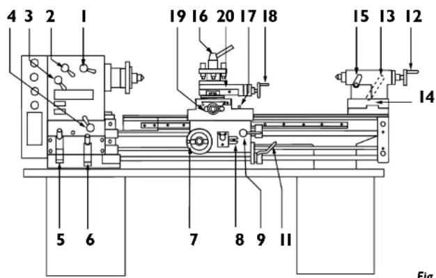
Fig. 2

natural_image
Technical line drawing of a lathe machine on a workbench, no text or symbols present
Deutsch
ab 26-05-1998 GENEMUIDEN NL G.M. Ensing Quality department
NL Nederlands
89/392/EEC 73/23EEC 89/336/EEC
frà 26-05-1998 GENEMUIDEN NL G.M. Ensing Quality department

RUS Russian
DÉCLARATION DE CONFORMITÉ (F)
89/392/EEC 73/23EEC 89/336/EEC
dès 26-05-1998
GENEMUIDEN NL
G.M. Ensing
Quality department

ERKLÆRING AYANSVARSFORHOLD (N)
89/392/EEC 73/23EEC 89/336/EEC
26-05-1998
GENEMUIDEN NL G.M. Ensing Quality department


Norsk
Produkt: Ferm dreiebenk formetall Type FM-760/300T.Art.nr.331710 Type FM-1000/350T.Art.nr.331730 Ferm, Genemulden, The Netherlands.
Lydtryksnivá (Lpα):< 82 dB(A)

89/392/EEC 73/23EEC 89/336/EEC
- READ THE INSTRUCTIONS FOR USE BEFORE YOU USE THE METAL TURNING LATHE!
- I.USE
- SPECIAL SAFETY REGULATIONS
- INSTALLATION
- ELECTRICAL CONNECTIONS
- OPERATING HANDLES
- (See Illustration 2)
- FIXED HEAD
- GEARBOX
- CARRIAGE
- LOOSEHEAD
- MAINTENANCE
- CE DECLARATION OF CONFORMITY (UK)
- prEN12840, EN60204-1, EN61029-1 EN55014, EN61000-3-2, EN61000-3-3, EN55104
- Deutsch
- NL Nederlands
- RUS Russian
- DÉCLARATION DE CONFORMITÉ (F)
- ERKLÆRING AYANSVARSFORHOLD (N)
- 26-05-1998
- Norsk
Brand : Ferm
Model : BLM1003
Category : Metal Lathe