
EKS 1000 L - Water heaters and boilers Nibe - Free user manual and instructions
Find the device manual for free EKS 1000 L Nibe in PDF.


| Product Type | Hot Water Storage Tank (Electric) |
| Brand | Nibe |
| Model | EKS 1000 L |
| Capacity | 1000 liters |
| Dimensions (Height x Diameter) | 2000 mm x 1100 mm |
| Weight (empty) | 200 kg |
| Power Supply | 230 V ~ 50 Hz |
| Heating Element Power | 6 kW |
| Max Operating Temperature | 90 °C |
| Insulation Type | Polyurethane foam |
| Energy Efficiency Class | C |
| Standby Heat Loss | 1.5 kWh/24h |
| Pressure Rating | 10 bar |
| Safety Valve Included | Yes (8 bar) |
| Temperature Control | Thermostat with adjustable range |
| Overheat Protection | Built-in thermal cut-off |
| Material | Steel with enamel lining |
| Corrosion Protection | Magnesium anode |
| Installation | Indoor, floor standing |
| Connection Size | 1 inch (25 mm) |
| Maintenance | Annual inspection of anode and safety valve |
| Spare Parts Availability | Replacement anodes, heating elements, thermostats |
| Warranty | 5 years on tank, 2 years on electrical components |
Frequently Asked Questions - EKS 1000 L Nibe
User questions about EKS 1000 L Nibe
0 question about this device. Answer the ones you know or ask your own.
Ask a new question about this device
Download the instructions for your Water heaters and boilers in PDF format for free! Find your manual EKS 1000 L - Nibe and take your electronic device back in hand. On this page are published all the documents necessary for the use of your device. EKS 1000 L by Nibe.
USER MANUAL EKS 1000 L Nibe
natural_image
Three cylindrical industrial tanks with circular components and yellow connectors, no visible text or symbolsEKS 500, 750, 1000
User and installer manual EKS 500, 750, 1000 L
This manual describes installation and service for implementation by specialists.
The manual must be left with the customer.
General
EKS 500, 750, 1000 L is designed and manufactured according to good technical practitioner to ensure safe usage.
Pressure Equipment Directive 2014/68/EU Article 4 point 3.
Serial number
This appliance can be used by chil aged from 8 years and above and
sons with reduced physical, sensory
mental capabilities or lack of experience
and knowledge if they have been given
supervision or instruction concerning
of the appliance in a safe way a stand the hazards involved. Children
not play with the appliance. Clean and user maintenance shall not be by children without supervision.
Rights to make any design or modifications are reserved.
©NIBE 2017.
The type plate bearing the serial number can be four forene top of the product.

Caution
Always give the product's serial number when reporting a fault.
Recovery
to underve the disposal of the packaging to the in- shall staller who installed the product or to special waste stations.
Do not dispose of used products with normal made household waste. It must be disposed of at a special waste station or dealer who provides this type service.
techmiper disposal of the product by the user results in administrative penalties in accordance with current legislation.
Symbols

NOTE
This symbol indicates danger to person or machine.

Caution
This symbol indicates important information about what you should observe when maintaining your installation.

TIP
This symbol indicates tips on how to facilitate using the product.
Marking
CE The CE mark is obligatory for most products sold in the EU, regardless of where they are made.
Inspection of the installation
Current regulations require the heating installation to be inspected before it is commissioned. The inspection be carried out by a suitably qualified person.
| √ | DateSignat | |||
| Hot water (page 21) | ||||
| Shut o valves | ||||
| Mixing valve | ||||
| Cold water (page 21) | ||||
| Shut o valves | ||||
| Non-return valve | ||||
| Safety valve | ||||
| Electricity (page 22) | ||||
| Connected supply | ||||
| Sensors | ||||
For the User
Maintenance
The safety valve must be inspected regularly (about 4 times a year) to prevent blockages. To inspect the valve, open the safety valve manually and check that water flows through the overflow pipe. If this does not happen, the safety valve is defective and must be changed.
The safety valve sometimes releases a little water after hot water has been used. This discharge is caused by the expansion of cold water entering the water heater, resulting in a pressure increase, whereby the safety valve opens.
Emptying
- Turn o the power to the water heater.
- Shut o the incoming cold water.
- Open the drain connection, or the drain valve (enclosed) if installed.
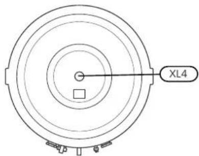
During draining, air must be let into the water heater by loosening a hot water connector (XL4) or opening a hot water tap.
To ensure that the water heater drains completely, a hose, or a pipe, with an outlet below the lowest level of the water heater must be attached to the drain connection or drain valve. When installed in a location that is exposed to the risk of frost, the water heater must be emptied whenever it is not in operation. Freezing will result in the water heater bursting.
Dealing with malfunctions
If the water fails to heat up, check the fuses in the electrical distribution unit. If none of the fuses have blown, the problem may be that the temperature limiter has tripped as a result of a fault in the water heater. Once the fault has been remedied, the temperature limiter can be reset. This must be done under the supervision of a qualified electrician.
Service
When a service is necessary, contact the main contractor. You must always state the installation date and manufacturing number (PF3).
Only spare parts supplied by NIBE AB in Markaryd may be used.
For the Installer
General
The water heater consists of a steel vessel, with a copper lining to protect against corrosion.
The water heater is designed and manufactured for a maximum cut-o pressure of 10 bar. Drain valve with plug
Maximum permitted temperature is 90 °C.
The insulation on EKS 500, EKS 750 and EKS 1000 prises Neopor and polyester eece with a thickness of 100 mm, which provides excellent heat insulation. The insulation and grey plastic outer cladding can be removed easily to simplify moving the water heater through doorways, for example.
EKS 500 can be equipped with up to two immersion plug heaters and EKS 750 and EKS 1000 can be equipped with up to three immersion heaters.
The connection diameter is G50 and the maximum immersion heater length for EKS 500 is 650 mm and for EKS 750 and EKS 1000 is 750 mm.
Transport
EKS 500, 750, 1000 L should be transported and stored vertically in a dry place. The EKS 500, 750, 1000 L may, however, be carefully laid on its back when being moved into a building.
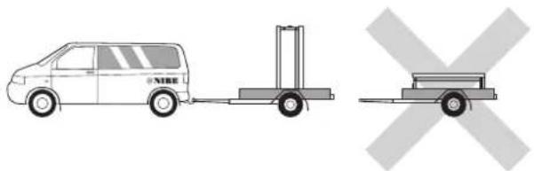
Assembly
The water heater is only designed for upright installation.
The water heater is unscrewed from the pallet and lifted into position, using the lifting eye.
EKS 500 is equipped with a lifting eye in the top.
The top insulation must be removed to access the lifting eyes on the EKS 750 and EKS 1000.
Position EKS 500, 750, 1000 L on a rm base that can take the weight, preferably on a concrete oor or foundation. Use the product's adjustable feet to obtain a horizontal and stable set-up.
The area where EKS 500, 750, 1000 L is located must be equipped with oor drainage.

Supplied components

Drain valve with plug

Cover discs

Plastic cover
Component positions
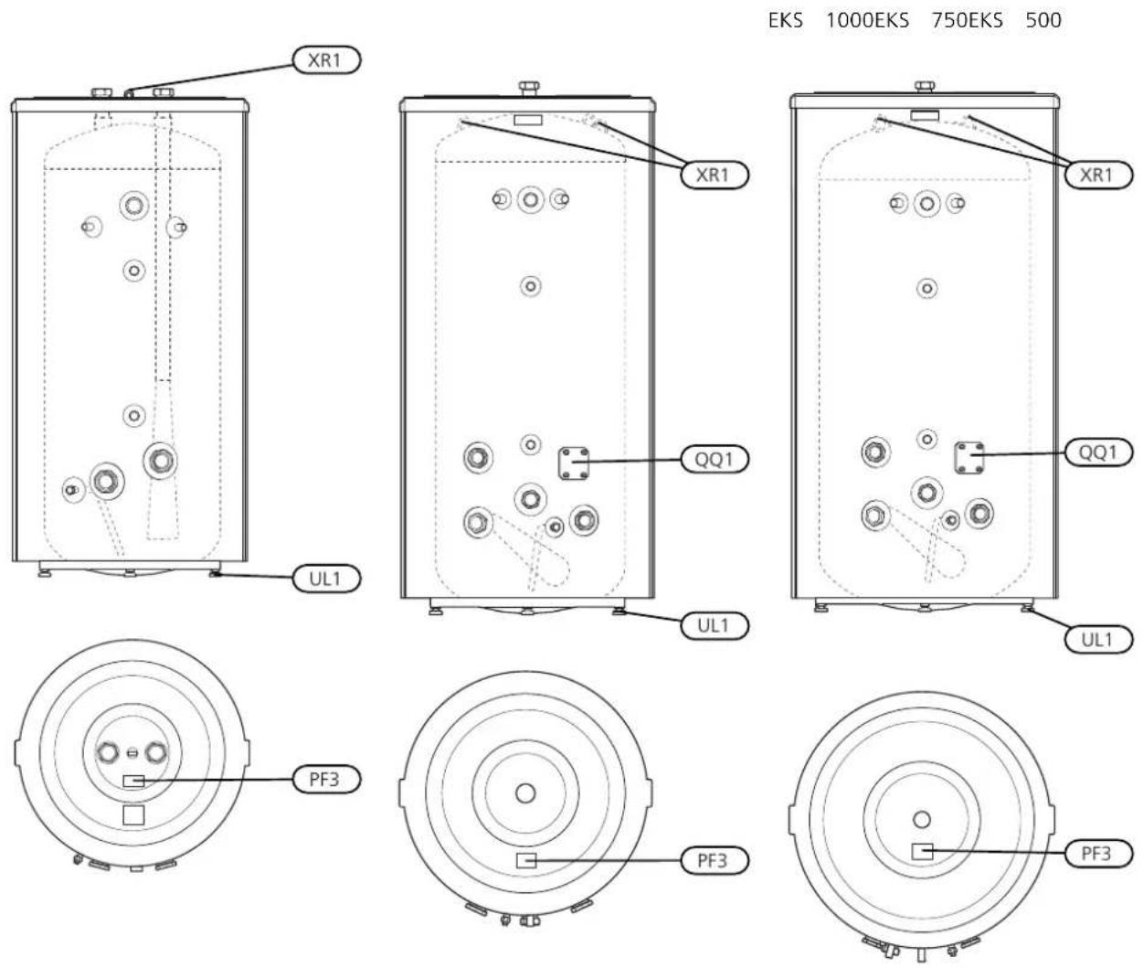
| NameDesignation | |
| Inspection hatchQQ1 | |
| Adjustable feetUL1 | |
| Lifting eyeXR1 | |
| Serial number platePF3 |
Removing the insulation
The insulation can be removed to facilitate handling in conned spaces.
■ Lift o the plastic top and the top insulation.
- On EKS 500, the lifting eye on the top must be un-screwed rst.
■ Remove the joining plates holding the insulated jacket halves together.
- Unhook and remove the insulated jacket halves, the outer diameter of the heater becomes approx. 200 mm less without the insulated jackets.
The gure shows EKS 1000 with insulation.
ling the joining plate.
Insulation removedDo not use any
UN
UN
Carry out assembly in reverse order.
Install the enclosed insulation plugs around each connection, and in the hole for the lifting eye on EKS 500. Finally, t all the enclosed cover discs on each connection by pressing them over the connections.
NOTE
Fit the cover discs and the insulation plugs before installing the pipe.
NOTE
In certain cases, more insulation plugs are enclosed than are required.
Installation
Filling
The water heater must be installed in an upright position. heater is lled by rst opening a hot water tap in the system and then opening the shut-o valve for incoming cold water. This valve must then be fully open during operation. The hot water tap can only be shut-o when the water heater is lled, which is when only water comes out of the hot water tap (initially air-water mixture comes out of the tap).
Fit the enclosed cover discs before pipe installation. The cover discs, with self-adhesive backs, must be installed on the relevant connection, by pushing them over the connections.
All connections (including connections or holes left by the lifting eyes that are not used) must be insulated to minimise energy losses.
Immersion heaters
| Free | spaceOutput | ||||
| 250 | mm1500 | WIU | 31 | ||
| 260 | mm2250 | WIU | 33 | ||
| 280 | mm3000 | WIU | 34 | ||
| 400 | mm4500 | WIU | 36 | ||
| 400 | mm6000 | WIU | 39 | ||
| 400 | mm7500 | WIU | 310 | ||
| 400 | mm9000 | WIU | 311 |
Pipe installation
The water heater must be provided with a drain valve, shut-off valve, non-return valve, mixer valve, safety valve, and a vacuum valve as per applicable standards, as well as with a thermometer and pressure gauge.
Install the enclosed drain valve on the drain connection (XL12). Remove the compression ring and compression ring nut from the drain valve and install the valve using the existing compression ring, compression ring nut, and support bush. Replace the compression ring with a plug on the open side of the drain valve.
The water heater must be provided with a mixer valve, which limits the temperature of outgoing hot water to 60 °C. If this valve is not tted, some other measure must be taken to prevent the risk of scalding.
The safety valve must be set to maximum 9 bar (0,9 MPa) and its overflow pipe must run unobstructed to the drain. The overow pipe must be the same size as the safety valve. The overow pipe must be routed downwards along its entire length and be frost proof. The outlet of the overow pipe must be visible.

NOTE
Fit the cover discs before the pipe installation is made
Electrical installation

NOTE
Electrical installation and service must be carried out under the supervision of a qualified electrician, and in accordance with applicable electrical safety regulations.
EKS 500 has two immersion heater connections for a maximum output of 2 x 9 kW. A separate supply from group central is routed to each immersion heater.
EKS 750 and EKS 1000 have three immersion heater connections for a maximum eect of 3 x 9 kW. A separate supply from group central is routed to each immersion heater.
Each immersion heater is supplemented with junction box type K11 (2-pole thermostat, 3-pole temperature limiter).
Do not modify or reconnect.

NOTE
The water heater must be completely lled with water before it is switched on.
Technical data
Dimensions
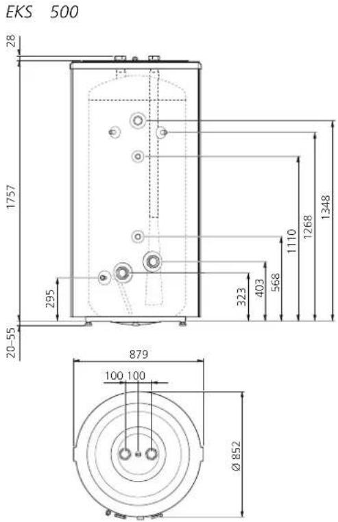
EKS 1000


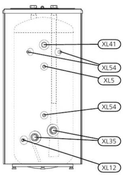
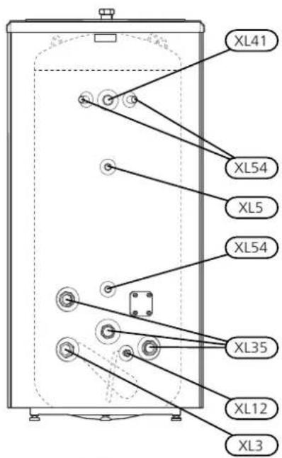

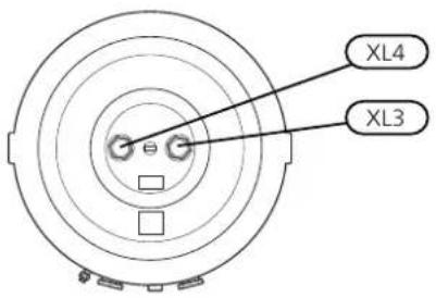
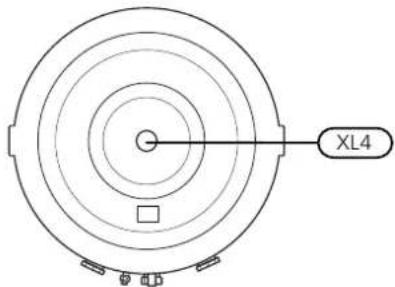
Pipe dimensions
| Connection | |
| G50XL3 Cold water con | |
| G50XL4 Hot water con | |
| G20XL5 HWC connection | |
| ∅ 22 mmXL12 Drain con | |
| G50XL35 Connection for | |
| G32XL41 HWX connectio | |
| G15XL54 Connection for |
Technical specifications
| EKS 1000E | ||||
| 1 | CEciency | class | ||
| 1052950852mmDiamet | ||||
| 866766668mmDiamete | ||||
| 205219771757mmHeigl | ||||
| 232522101970mmRequ | ||||
| 220185138kgNet weigh | ||||
| Max. output | kW 3x92x9 | |||
| Max cut-o pressure | (bar) | 10 | ||
| Max. operating temperature | °C | 90 | ||
| Heat content at 80°C | 46,5kWh | 68,5 | 92 | |
| ^2 | 214516001050litreEquiv | |||
| Heating time 10 - 60 °C, EKS 500 2 x 9 kW, EKS 750 and EKS 1000 3 x 9 kW | min. | 100 | 130 | |
| Corrosion protection | Copper | |||
| Part No. | 084 099 | 084 101 | 084 102 | |
^1 Scale for the product's eciency class A+ - F.
^2 At incoming temperature 10^ C and hot water draining at 48 l/min.
Energy labelling
| Supplier | NIBE | |||
| Model | EKS 500 | EKS 750 | EKS 1000 | |
| Energy eciency class | C | |||
| Heat loss | W | 111 | 126 | 145 |
| Volume | I | 492 | 740 | 990 |
Accessories
Not all accessories are available on all markets.
Immersion heater IU
Immersion heater IU 31 - IU 311
See table (page 21)
Connection box K11
Connection box with thermostat and overheating protection.
(When connecting Immersion heater IU)
Part no. 018 893
natural_image
Diagram showing a van connected to a lift truck and a cross symbol (no text or labels)Montage


- EKS 500, 750, 1000
- General
- Serial number
- Caution
- Recovery
- Symbols
- NOTE
- TIP
- Marking
- Inspection of the installation
- For the User
- Maintenance
- Emptying
- Dealing with malfunctions
- Service
- For the Installer
- Transport
- Assembly
- Removing the insulation
- Installation
- Filling
- Pipe installation
- Electrical installation
- Accessories
- Immersion heater IU
- Connection box K11
- Montage
Brand : Nibe
Model : EKS 1000 L
Category : Water heaters and boilers