
BA-ST 9050-2FE - Water heaters and boilers Nibe - Free user manual and instructions
Find the device manual for free BA-ST 9050-2FE Nibe in PDF.


| Product Type | Hot Water Storage Tank (Indirectly Heated) |
| Model | BA-ST 9050-2FE |
| Brand | Nibe |
| Storage Volume | 344 L |
| Coil Area | 5 m² |
| Max Tank Operating Temperature | 85 °C |
| Max Coil Operating Temperature | 110 °C |
| Max Tank Operating Pressure | 6 bar |
| Max Coil Operating Pressure | 10 bar |
| Coil Power (70/10/45 °C) | 82 kW |
| Heat Exchanger Type | Large surface coil (stainless steel) |
| Corrosion Protection | Ceramic enamel + isolated magnesium anode |
| Insulation | Specially selected thermal insulation, foam |
| Energy Efficiency Class | C (EU regulation 812/2013) |
| Standing Loss | 96.7 W |
| Overall Height (with housing) | 1694 mm |
| Overall Width (diameter approx.) | 600 mm |
| Weight (empty) | 198 kg |
| Connection Sizes | Hot water outlet: 1" male; Cold water inlet: 1" male; Coil supply/return: 1 1/4" male; Circulation: 3/4" male |
| Electric Heating Unit Ready | Yes, G 1 1/2" connection for MEL or WP-6.8 unit |
| Inspection Opening Diameter | 120 mm |
| Temperature Display | Dial thermometer |
| Safety Valve Required | Yes, at cold water inlet (mandatory) |
| Maintenance | Annual anode inspection, cleaning every 2 years |
Frequently Asked Questions - BA-ST 9050-2FE Nibe
User questions about BA-ST 9050-2FE Nibe
0 question about this device. Answer the ones you know or ask your own.
Ask a new question about this device
Download the instructions for your Water heaters and boilers in PDF format for free! Find your manual BA-ST 9050-2FE - Nibe and take your electronic device back in hand. On this page are published all the documents necessary for the use of your device. BA-ST 9050-2FE by Nibe.
USER MANUAL BA-ST 9050-2FE Nibe
natural_image
Line drawing of a cylindrical container with a side knob and lid (no text or symbols)Installation and Operating
Manual
BA-ST 9030 - 1FEDC
BA-ST 9040 - 1FEDC
Hot Water Storage Tank
with large surface coil
Content
1 General 3
Introduction 3
Intended Use 3
2 Design 4
3 Installation 5
Location of the Storage Tank ____ 5
Housing Disassembly 5
Installation Requirements 6
4 Connection and start-up \_\_\_\_ 7
Connection 7
Start-Up 7
Thermal Insulation of the System 8
Warnings and Practical 8
Recommendations 8
5 Maintenance 9
Inspection of the Protective 9
Magnesium Anode 9
Measurement of the Protective Magnesium
Anode Wear 9
Replacement of the Protective Magnesium Anode_9
Cleaning of the Storage Tank ____ 10
6 Accessories and spare parts \_ 11
7 Service 12
8 Recycling and disposal \_\_\_\_ 12
9 Technical data 13
Dimensions 14
All installation diagrams in this manual do not replace the system design; they can only be used for illustrative purposes. The product is not intended for use by persons with reduced physical fitness/mental efficiency or without sufficient experience and knowledge, if they are not supervised or instructed by a person responsible for their safety. Operation of the product by children is strictly prohibited.
We reserve the right to make the product design changes and changes in the manual.
©NIBE 2016
1 General
Introduction
Thank you for your confidence and choice of equipment by NIBE. To fully benefit from the advantages of this product, please read this Manual before using it, and in particular chapters relating to the application, installation and maintenance, and warranty. Please keep this Manual in a safe place for future reference.
CAUTION
Sections of the Manual relating to the installation, inspection and maintenance are intended for the qualified installer.
CAUTION
The manufacturer shall not be held liable for any damages caused by failure to comply with the recommendations and observations contained in this Manual.
Intended Use
NIBE hot water storage tanks with a large surface coil are only intended for heating up, storage and supply the domestic hot water.
Vertical storage tank BA-ST 9030/9040-1FEDC with a large surface coil is designed to heat and store hot water in systems with one heat source, e.g. solar heating system, central heating boiler or a fi replace and with a water jacket. The storage tank enables trouble-free operation with almost any central heating system with forced circulation. It is easy to install, safe and comfortable to use, if installed and operated in accordance with the advices contained in this Manual. The heated water can be supplied to several intake points at various, mutually distant locations, such as, a bathtub, washbasin, sink, etc.
CAUTION
BA-ST 9030/9040 - 1FEDC storage tanks with one high capacity coil are designed to heat up and supply water for domestic purposes. Any inappropriate use, not in compliance with its intended use is not permitted. Neither manufacturer nor supplier shall be responsible for damages resulting from this.

natural_image
Line drawing of a cylindrical container with a side hole and a small circular opening (no text or symbols)Fig. 1 BA-ST 9030/9040 - 1FEDC hot water storage tank.
2 Design
Vertical storage tank BA-ST 9030/9040 - 1FEDC with a large surface coil is a pressure equipment, i.e. the pressure within the storage tank and coil are equivalent to the pressures in the corresponding systems.
Storage tank is made of high quality steel and is equipped with one helical coil that can simultaneously operate with independent heat source, e.g. a solar heating system, fi replace with water jacket or central heating boiler. The hot water tank is protected against corrosion by ceramic coating and insulated protective magnesium anode. Thermal insulation of the tank is a specially selected insulation that provides excellent thermal insulation properties of all devices. Storage tanks have aesthetic plastic housing, a temperature indicator, inspection opening and connectors for mounting electric heating unit and connecting the hot water circulation.
-TIP
BA-ST 9030/9040 - 1FEDC is ready for the installation of a heating unit containing an electric heater with thermostat and thermal switch.

Fig. 2 Section of the BA-ST 9030/9040 - 1FEDC storage tank.

Fig. 3 Side view of the BA-ST 9030/9040 - 1FEDC storage tank.
Description:
- Upper insulation of the storage tank
- Hot water intake pipe
- Protective magnesium anode
- Large surface coil
- Thermal insulation
- Enamelled tank
- Cold water supply pipe
- Lower insulation of the storage tank
- Thermometer
- Inspection opening with 1½" Female sleeve
- Hot water intake connector pipe
- Coil supply connector pipe
- Hot water circulation connector pipe
- Temperature sensor cover
- Connection of return line from the coil
- Cold water supply connector pipe
3 Installation
Location of the Storage Tank
Storage tank can be installed in any room protected against temperatures below 0 °C and convenient for the user (e.g. in the basement, boiler room, etc.). Location and manner of installation must ensure trouble-free maintenance and servicing of the unit in the future. However, we recommend installation of the buffer tanks in the immediate vicinity of the main heat source in order to avoid unnecessary heat losses. Consider the filled tank weight when selecting its location. As a rule, select the device location in a way allowing the rational routing of both the hot water and the heating lines. Insulate thoroughly all hydraulic lines and the storage tank fittings in order to avoid any energy losses.
If space for the installation of the magnesium bar anode (used as standard), you can use the appropriate titanium anode (that should be installed in accordance with the anode manufacturer's instructions) or the appropriate magnesium chain anode. For the specification of the protective anodes available at NIBE, see Section 6 Accessories and Spare Parts.

Fig. 4 Min clearance for the replacement of the protective magnesium anode.

Fig. 5 Levelling the unit.
The storage tank stands on three feet that can be adjusted within the range from 0 to 15 mm to level the tank.
CAUTION
For the minimum clearances to be observed when installing the storage tank, see Table 3.
Housing Disassembly
Removable housing with thermal insulation facilitates transport and installation of the storage tank. Disassembly the housing in the following order (see Fig. 6):
- Remove the Temperature gauge, plug of the heating element connector pipe and blanking plate of the inspection opening (1).
- Remove the upper cover of the housing together with thermal insulation (2).
- Remove the plugs from the connector pipes and black bushings (3).
- Remove the fixing screws and the strip connecting the housing jacket (4).
- Remove the jacket surrounding the tank (housing jacket, 5).
- Remove the four-piece thermal insulation (6).
After the installation of the storage tank in its final location, reinstall the removed components in the reverse order.
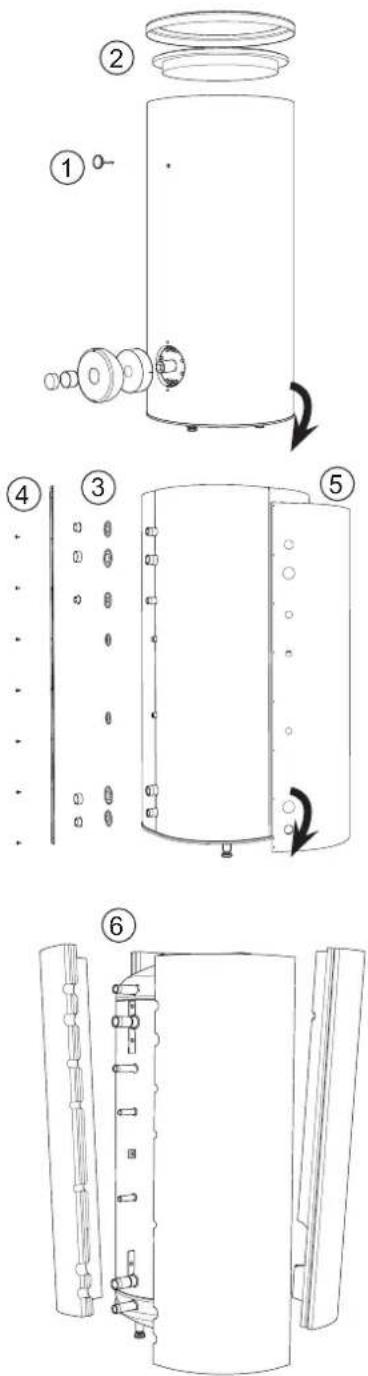
Fig. 6 Housing and thermal insulation disassembly.
Installation Requirements
-CAUTION
Installation and commissioning of the storage tank shall only be done by appropriately qualified installer. The installer should inform the user of the functions of the product and provide the necessary information on its safe use.
Protection against overpressure shall be made in accordance with the relevant regulations in force.
Connect the storage tank to the water supply system of water pressure at least 1 bar and max 6 bar and to the heating systems where parameters of the heating medium may not exceed the allowable operating conditions of the coil (see Table 4 Technical data). Install a pressure reducer if the pressure at the cold water inlet to the tank is higher than allowed.
Connect the heating and water supply systems in accordance with the installation diagram (see Fig. 7.)
Pressure increases during heating the water in the storage tank. Therefore, the appropriate safety valve must be installed in storage tank, at the cold water inlet that will protect the storage tank against over-pressure. During heating the water, small and temporary water flow from the safety valve can occur, which indicates that the pressure has increased above the rated value, which triggered the valve. This may in no way be prevented. Blocked safety valve can cause equipment failure. Drain the outflow from the safety valve to the sewerage or drain grate. Safety valve drain line should be installed with a decline, in an environment free of freezing and remain open to the atmosphere. The manufacturer is not responsible for flooding the room through the safety valve.
-TIP
In order to minimize the flow of water from the safety valve associated with the thermal expansion of the liquid, it is advisable to install a suitable expansion vessel at the cold water connection (see Fig. 7 item 9.)
TIP
We recommend installing a strainer in order to protect the pumps, check valve and the components of the heating system.
CAUTION
Installation of the appropriate safety valve in the cold water supply line protecting the unit against overpressure is mandatory!
CAUTION
Installation of necking of any kind (such as reducers, dirt pockets, etc.) and cut-off valves between the storage tank and the safety valve is not allowed. Only a T-pipe with a drain valve and a T-pipe with an expansion vessel may be installed in these line sections.
CAUTION
Never block the safety valve or drain line. This can cause a dangerous overpressure in the storage tank.
CAUTION
When heating water, slight, temporary discharge from the safety valve can occur. This is a correct safety valve function. Any attempt to interfere in its operation can lead to the danger and destruction of the storage tank.
CAUTION
Never use the equipment with clogged safety valves.

flowchart
graph TD
    A["①"] --> B["②"]
    B --> C["DHW"]
    B --> D["⑦ ⑥ ②"]
    D --> E["Supply of the coil"]
    D --> F["Hot water circulation"]
    A --> G["③"]
    G --> H["⑨ ⑤ ②"]
    H --> I["Return from the coil"]
    A --> J["④ to sewerage"]
    J --> K["Water supply system"]
Fig. 7 Installation diagram of the BA-ST 9030/9040 - 1FEDC storage tank with one coil.
- BA-ST 9030/9040 - 1FEDC storage tank.
- Cut-off valve.
- Safety valve.
- Drain valve.
- Pressure reducer (opti on, if the pressure in the system exceeds the allowable value).
- Strainer.
- C/H circulating pump.
- Hot water circulating pump.
- Hot water expansion vessel.
4 Connection and start-up
Connection
After the installation and levelling the tank, follow the procedure below (for the connector pipe numbers, refer to Fig. 3):
- Remove protecting plugs from the connector pipes
- Connect the hot water intake line (11).
- Connect the cold water supply line together with the required safety valves (16).
- If the system has the hot water circulation system, connect it to the connector pipe (13). Otherwise, plug the pipe.
- Connect the supply (12) and return (15) of the heating medium to the coil.
Start-Up
Fill the storage tank with water and vent it after making correct connections.
CAUTION
If there is an electric heating module installed in the storage tank, fill the tank with water before connecting it to the electrical installation.
Filling and venting the hot water storage tank:
- Open the cold water cut-off valve at the inlet and the hot water intake point.
- Fill the storage tank until obtaining uniform water outflow at the hot water intake point. Close the intake points.
- Fill the coil with the heating medium, and vent it.
- Check tightness of the entire system.
When properly filled and vented, the storage tank is ready to use.
-TIP
We recommend connecting the tank connector pipes with the system lines by means of unions to allow disconnection of the tank, if required.
CAUTION
Open the hot water intake valves before heating the system up for the first time or after a longer break in its operation in order to check whether the storage tank is filled with water and the cut-off valve at the cold water inlet is not closed.
Thermal Insulation of the System
In order to minimize thermal energy losses, insulate all connector pipes, pipelines and temperature sensor covers thoroughly after the installation of the unit and performance of the leak proof test. For this purpose, use thermal insulation of correctly selected thickness and thermal insulation parameters.
-TIP
Lack of thermal insulation, its incorrect thickness or insulation made of inadequate materials will cause decrease of thermal insulation properties of the unit and the system.
Warnings and Practical Recommendations
CAUTION
To prevent bacterial growth we recommend to make sure a periodically increase of hot water temperature for a shorter time at regular intervals e.g. every 14th day.
We recommend the following:
- Check the operation of the safety valve as described by the manufacturer of the valve in order to check whether it is not clogged.
- Clean the inside of the storage tank periodically. Cleaning intervals depends on the hardness of the water present in a given area.
- To ensure optimum protection of the storage tank against corrosion, we recommended checking the level of wear of the isolated magnesium anode once a year.
- In the systems with the electric heating unit, ensure that the electrical installation is properly protected by protective circuit.
-
In order to eliminate any odour of hydrogen sulphide (caused by bacteria in the oxygen deficient water), we recommend observing the periodic cleaning of the tank and replacement of the anode and, in addition periodically increase the hot water temperature in tank to prevent bacterial growth.
-
Limit the setpoints of the heating medium temperature controllers in the storage tank supply lines to 80 °C in order to avoid triggering of the thermal cut-off in the electric heating module.
- In order to reduce the possibility of scalding by the water, we recommended to set the water heating temperature in the storage tank (of both the heating unit and the coil) so, that it does not exceed 60 °C. This will also help to extend the life of the storage tank.
- Report any malfunctions in the storage tank operation to the authorized service centres. You can find the complete list of our authorized service centres at our website.
It is forbidden to:
- Activate the heating medium circuit or electric heating unit if the tank is not filled with water.
- Use the storage tank, if you find any malfunction of the safety valve.
- Install any device (such as cut-off and/or check valves, etc.) between the storage tank and the safety valve (except T-pipes).
- Make any unauthorized repairs.
- Stop water leaks from the safety valve.
- When heating with only the electric unit, the coil circuits may not be isolated.
5 Maintenance
Periodic inspections and maintenance are the conditions of continuous operational readiness, reliability and a long service life of the product.
Maintenance activities include the following:
- Routine inspections and replacement of the protective magnesium anode.
- Cleaning of the storage tank.
CAUTION
Check the safety valve performance as specified by the valve manufacturer periodically (min. every 14 days) or before each start-up of the heater after decommissioning.
Inspection of the Protective Magnesium Anode
Storage tank BA-ST 9030/9040 - 1FEDC with coil is, in order to protect them against corrosion, coated inside with ceramic enamel and in addition, protected with isolated protective magnesium anode. The anode corrodes first under normal operation, thus protecting the storage tank jacket. Therefore, you have to inspect its condition from time to time. Corrosion rate of the protective anode is different and depends upon the quality of water in the area. We recommend checking the protective anode condition once a year in order to ensure optimum corrosion protection.
-TIP
The use of the isolated anode allows you to monitor the degree of wear of the anode by measuring the intensity of the protecting direct current without having to remove it and empty the tank (interrupting operation of the storage tank). This solution simplifies operation and additionally contributes to the reliability and long lifetime.

Fig. 8 Insulated protective magnesium anode.
Measurement of the Protective Magnesium Anode Wear
In order to check the degree of wear of the anode, do the following (see Fig. 11):
- Remove the housing cover together with thermal insulation.
- Disconnect the connecting conductor (protective) from the storage tank top head.
- Connect an electric meter (range in mA) between the protective conductor and the M5 threaded pin and measure the intensity of the protective direct current.
Intensity of the protective direct current should not be lower than 0.3 mA at full storage tank. If it is too low, remove the anode and check its wear visually. If the anode is significantly corroded (above 50 % loss), replace it immediately. Connect the anode protective conductor to the tank after the measurement.
CAUTION
If the current intensity measurements do not indicate any wear of the anode, its max operating time is not longer than 18 months. The anode should be replaced after this time.

Fig. 9 Measurement of the protective direct current intensity.
Replacement of the Protective Magnesium Anode
Replace the protective magnesium anode every 18 months (regardless the measurement). Instead of the magnesium anode, you can use the titanium anode. Install it in accordance with the anode installation manual.
CAUTION
Replace the protective magnesium anode every 18 months. Its timely exchange and proper installation are the conditions to maintain the warranty on the storage tank.
When replacing the magnesium anode, follow the procedure below (see Fig. 10):
- In units with the electric heating unit installed, disconnect power from the unit first.
- Switch the storage tank coil heaters OFF and wait until the water inside cools down.
- Cut-off the hot water supply and drain some water from the tank through the drain valve (see Fig. 7 item 4).
- Remove the housing cover together with thermal insulation (1).
- Remove the anode protective conductor (2).
- Remove the worn magnesium anode (3).
- Screw the new magnesium anode.
- Connect the anode protective conductor to the storage tank.
- Fill the tank with water and vent it as described in par. Start-Up.
- Check tightness of the installed anode.
- Reinstall the thermal insulation and the housing cover.
Once making the above steps, the storage tank is ready to use.
Ensure that the anode protective conductor is connected to the storage tank top head after installing the new isolated magnesium anode. Lack of contact between the anode and the tank will interfere operation of the anode and the tank will not be protected against corrosion.

Fig. 10 Replacement of the protective magnesium anode.
Connect the anode protective conductor to the M5 pin fixed to the top head of the storage tank.
-TIP
Ensure that the anode protective conductor is connected to the storage tank top head after installing the new isolated magnesium anode. Lack of contact between the anode and the tank will interfere operation of the anode and the tank will not be protected against corrosion.
Cleaning of the Storage Tank
Boiler scale is precipitated from the heated water during the storage tank operation. The amount of deposited scale depends on the water hardness, the operating temperature and operating time. Heating surfaces covered with boiler scale reduce the heat output of the storage tank, increase power consumption and extend the heating time. It is recommended to clean the storage tank from deposits at least once every two years. In the case of hard or very hard water, cleaning should be carried out at shorter intervals.
Storage tank cleaning procedure:
- Prepare a new inspection opening gasket. The old gasket may not be reused (for the list of the inspection opening gaskets, see Section 6 Accessories and Spare Parts).
- In storage tanks with the electric heating unit installed, disconnect power from the unit fi rst.
- Switch the storage tank coil heaters OFF and wait until the water inside cools down.
- Cut-off the hot water supply and drain the storage tank through the drain valve (see Fig. 7 item 4).
- Remove the inspection opening blanking plate and gasket.
- Remove the inspection opening screws and flanged cover and flush the storage tank and remove accumulated sludge and lime slurry. If necessary, remove lime deposits from the coil – this guarantees a proper heat exchange. Pay special attention to not damage the ceramic enamel coating.
- Replace a new gasket and the inspection opening flanged cover. Screw tightening torque: 25 ± 5 Nm.
- Fill the tank with water and vent it as described in par. Start-Up.
- Check tightness of the inspection opening.
- Replace the insulation and inspection opening blanking plate.
Once cleaned, the unit is ready to use.
-TIP
During mechanical cleaning, be careful to not damage the enamel. In the case of chemical cleaning, pay special attention to neutralize the chemicals used for cleaning.

Fig. 11 Installation of the inspection opening cover (mounting order).
6 Accessories and spare parts
Accessories and spare parts for BA-ST 9030/9040 - 1FEDC storage tank can be purchased at our distributors or authorized service centres.
Table 1. Inspection opening gaskets.
| Type of gasket | Inspection opening dia. | Storage tank model |
| Flanged gasketø 150 | ø120 | BA-ST9030 - 1FEDCBA-ST9040 - 1FEDC |
Table 2. Heating units.
| Storage tank model | Type | Heating unit power | Connector pipe dia |
| BA-ST9030 - 1FEDCBA-ST9040 - 1FEDC | MEL 1030 3 | 0 kW 112" | |
| WP-6.8 4,5 | kW 112" | ||
| MEL 1060 6 | 0 kW 112" |
Table 3. Protective anodes.
| Application | Connector pipe dia. | Type of anode | Amin* |
| BA-ST9030 - 1FEDC | 1" | Barø26x1100 | 1150 mm |
| BA-ST9040 - 1FEDC | 1 1⁄4" | Barø33x1100 | 1150 mm |
| BA-ST9030/9040 - 1FEDC | 1 1⁄4" | Titanium anode400 | 420 mm |
* - Amin - Minimal clearance for the replacement of the protective magnesium anode.
7 Service
Report any malfunctions in the buffer tank operation to the authorized service centres.
CAUTION
The storage tank may only be repaired / serviced by an authorized service since improper repair can cause safety risks, and the loss of product warranty.
8 Recycling and disposal
According to the NIBE rules, the products have been manufactured of high quality materials using the latest technologies and solutions that do not endanger the environment.
When selecting materials, we took into account both the possibility of reuse of materials (recycling) that can be disassembled and separated from materials unsuitable for recycling, as well as risks arising from the processing of materials not intended to reuse.
The purchased device consists in more than 90 % of parts that can be recycled and reused, so they are safe for the environment and human health.
CAUTION
In order to prevent damage to piping systems and environmental pollution, the product should only be disassembled and taken out of service by appropriately qualified specialists.
CAUTION
At end-of-life, take care that the product and all the equipment were disposed of in accordance with applicable regulations.
-TIP
The packaging, in which the product is delivered, is made mainly of materials suitable for recycling and utilization. After installation, you should ensure the proper disposal of packaging in accordance with applicable regulations.
9 Technical data
Table 4. Technical data.
| Parameter U/m | Storage tank model | |||
| BA-ST 9030 - 1FEDC BA-ST 9040 - 1FEDC | ||||
| Energy efficiency class* - C C | ||||
| Storage volume (V)* | 265 344,2 | ||||
| Standing loss (S)* | W | 94 | 96,7 | |
| Coil area | m2 | 3,85 | 5 | |
| Max tank operating temp. | °C | 85 | 85 | |
| Max allowable instantaneous temp. in the tank | °C | 95 | 95 | |
| Max coil operating temp. | °C | 110 | 110 | |
| Max tank operating pressure | bar | 10 | 6 | |
| Max coil operating pressure | bar | 10 | 10 | |
| Coil power ** | 70/10/45 °C | kW | 71 | 82 |
| Coil capacity** | 70/10/45 °C | l/h | 1720 | 2000 |
| Electric heating module connection | G 1 1⁄2" | |||
| Corrosion protection | ceramic enamel + magnesium anode | |||
| Magnesium anode dimensions | mm/cal | ø26x1100 / 1" | ø33x1100 / 1 1⁄4" | |
| Weight | kg | 165 | 198 | |
* Acc. to EU regulations No. 812/2013 & 814/2013.
** At the heating medium flow rate equal to 2.5 m3/h and the heating medium temperature 70 °C, supply water temperature 10 °C, and hot water temperature 45 °C.
Dimensions
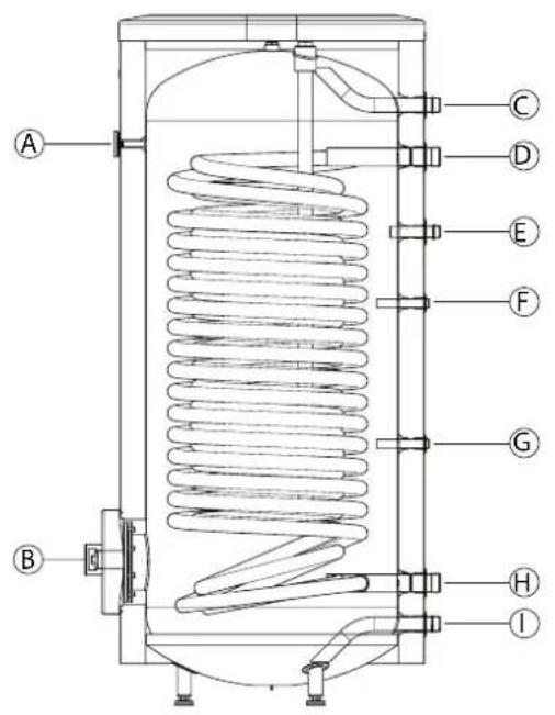
Rys. 12 Connector pipe of the BA-ST 9030/9040 - 1FEDCstorage tank
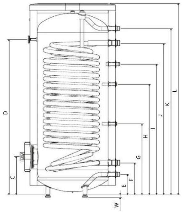
Fig. 13 Dimensions of the BA-ST 9030/9040 - 1FEDC storage tank

Table 5. Dimensions of nozzles.
| Connection | U/m | Dimensions of nozzles | ||
| BA-ST9030 - 1FEDC | BA-ST9040 - 1FEDC | |||
| A | Thermometer enclosure mm | 10 Female 10 | Female | |
| B | Inspection opening with 1 12 " Female sleeve | mm | 120 | 120 |
| C | Hot water outlet mm | 1" Male | 1" Male | |
| D | Coil supply | mm | 1" Male | 1 14 " Male |
| E | Hot water circulation | mm | 34 " Male 34 " | Male |
| F | Temp. sensor enclosure mm | 16 Female 16 | Female | |
| G | Temp. sensor enclosure mm | 16 Female 16 | Female | |
| H | Return from coil | mm | 1" Male | 1 14 " Male |
| I | Cold water input | mm | 1" Male | 1" Male |
Table 6. Dimensions.
| Wymiary | |||
| BA-ST9030 - 1FEDC | BA-ST9040 - 1FEDC | ||
| A mm | 780 | 883 | |
| B mm | 673 | 774 | |
| C mm | 315 | 323 | |
| D mm | 1325 | 1323 | |
| E mm | 167 | 175 | |
| F mm | 255 | 273 | |
| G mm | 507 | 606 | |
| H mm | 905 | 943 | |
| I mm | 1025 | 1113 | |
| J mm | 1205 | 1293 | |
| K mm | 1398 | 1417 | |
| L mm | 1634 | 1694 | |
| W | mm | 21 -0/+15 | |
Declaration of conformity
declare under our sole responsibility that the product
BA-ST 9010-1FE
BA-ST 9012-1FE
BA-ST 9015-1FE
BA-ST 9022-1FE
BA-ST 9030-1FE
BA-ST 9040-1FE
BA-ST 9040-1FEDC
BA-ST 9050-1FE
BA-ST 9075-1FE
BA-ST 9100-1FE
BA-ST 9022-2FE
BA-ST 9030-2FE
BA-ST 9040-2FE
BA-ST 9050-2FE
BA-ST 9075-2FE
BA-ST 9100-2FE
To which this declaration relates is in conformity is in conformity with requirements of following directives EC directive on:
Pressure Equipment (PE): 97/23/EC
Ecodesign Directive (ErP): 2009/125/EC
Restriction of Hazardous Substances (RoHS): 2011/65/EU
Regulation on Registration, Evaluation, Authorisation and Restriction of Chemicals (REACH): 1907/2006/EC
These pressurized equipments are covered by Article 3 in EU Directive 97/23/EC. As prescribed in item 3 of this article, the equipments are designed and manufactured in accordance with the sound engineering practice of a member state in order to ensure safe use. Such pressurized equipments must not bear the CE marking referred to in Article 15 in EU Directive 97/23/EC
The conformity was checked in accordance with the following EN-standards
*PN-EN ISO 9606-1:2014-02 Qualification testing of welders -- Fusion welding -- Part 1: Steels
*PN-EN ISO 14732:2014-01 Welding personnel -- Qualification testing of welding operators and weld...
*PN-EN ISO 3834-1:2007 Quality requirements for fusion welding of metallic materials - Part 1: Criteria ...
*PN-EN ISO 3834-2:2007 Quality requirements for fusion welding of mattalic materials – Part 2: Full quality...
*PN-EN ISO 5817:2014-05 Welding - welded joints in steel, nickel, titanium and their alloys...
*PN-EN ISO 6520-1:2009 Welding and allied processes - Classification of geometric imperfections in...
*PN-EN ISO 15609-1:2007 Specifications and qualification of welding procedures for metallic materials...
*PN-EN ISO 15614-1:2008/A2:2012 Specifications and qualification of welding procedures for metallic...
*PN-EN 10204:2006 Metallic products - type of inspection documents
*DIN 4753-3:2013-02 Water heaters, water heating installations and storage water heaters for drinking....
*PN-EN 12897:2006 Water supply - Specification for indirectly heated, not vented (closed)...
Markaryd 2016-01-20
Kenneth Magnusson Kenneth Magnusson
Quality and Environmental

Product Management Manager
AT
NIBE Energy Systems Ltd, 3C Broom Business Park, BridgeWay, Chesterfield S41 9QG
Tel: 0845 095 1200 Fax: 0845 095 1201 E-mail: info@nibe.co.uk www.nibe.co.uk
NL
NIBE Energietechniek B.V., Postbus 634, NL 4900 AP Oosterhout
Tel: 0168 477722 Fax: 0168 476998 E-mail: info@nibenl.nl www.nibenl.nl
NO
© „EVAN” 17, per. Boynovskiy, Nizhny Novgorod
Tel./fax +7 831 419 57 06 E-mail: info@evan.ru www.nibe-evan.ru



- Installation and Operating
- Manual
- BA-ST 9030 - 1FEDC
- BA-ST 9040 - 1FEDC
- Content
- General 3
- Design 4
- Installation 5
- Connection and start-up \_\_\_\_ 7
- Maintenance 9
- Accessories and spare parts \_ 11
- Service 12
- Recycling and disposal \_\_\_\_ 12
- Technical data 13
- General
- Introduction
- CAUTION
- Intended Use
- Design
- -TIP
- Installation
- Location of the Storage Tank
- Housing Disassembly
- Installation Requirements
- -CAUTION
- TIP
- Connection and start-up
- Connection
- Start-Up
- Thermal Insulation of the System
- Warnings and Practical Recommendations
- We recommend the following:
- It is forbidden to:
- Maintenance
- Inspection of the Protective Magnesium Anode
- Measurement of the Protective Magnesium Anode Wear
- Replacement of the Protective Magnesium Anode
- Cleaning of the Storage Tank
- Accessories and spare parts
- Service
- Recycling and disposal
- Technical data
- Dimensions
- Declaration of conformity
Brand : Nibe
Model : BA-ST 9050-2FE
Category : Water heaters and boilers