
VPB 500-1000 - Water heaters and boilers Nibe - Free user manual and instructions
Find the device manual for free VPB 500-1000 Nibe in PDF.


| Product Type | Buffer tank / hot water storage tank |
| Brand | Nibe |
| Model | VPB 500-1000 |
| Available capacities | 500 liters, 1000 liters |
| Dimensions (500L) | Diameter approx. 790 mm, height approx. 1800 mm |
| Dimensions (1000L) | Diameter approx. 990 mm, height approx. 2100 mm |
| Dry weight (500L) | Approx. 150 kg |
| Dry weight (1000L) | Approx. 250 kg |
| Material | Steel with enamel coating |
| Insulation | Polyurethane foam, thickness 50-100 mm |
| Max operating pressure | 6 bar (test pressure 10 bar) |
| Max operating temperature | 95 °C |
| Connections | Flow and return for heating system, cold water inlet, hot water outlet |
| Primary function | Thermal energy storage for heating systems, peak load buffer |
| Secondary function | Domestic hot water preparation (if equipped with internal coil) |
| Installation | Indoor, floor standing |
| Maintenance | Annual visual inspection, check pressure relief valve, clean connections |
| Safety devices | Temperature and pressure relief valve (TPR), thermostat (if applicable) |
| Spare parts availability | Replacement gaskets, thermostat, anode rod (if equipped), valves |
| Repairability | Serviceable by qualified technician; insulation is not replaceable |
Frequently Asked Questions - VPB 500-1000 Nibe
User questions about VPB 500-1000 Nibe
0 question about this device. Answer the ones you know or ask your own.
Ask a new question about this device
Download the instructions for your Water heaters and boilers in PDF format for free! Find your manual VPB 500-1000 - Nibe and take your electronic device back in hand. On this page are published all the documents necessary for the use of your device. VPB 500-1000 by Nibe.
USER MANUAL VPB 500-1000 Nibe
natural_image
Illustration of a cylindrical water heater with multiple circular components and a small labeled component (no text or symbols on the body)User and Installer manual
VPB 500 UK
Indirect heated storage water heater
Table of Contents
41 Important information
72 For the User
83 For the Installer
174 Technical data
20Item register
1 Important information
Safety information
This manual describes installation for implementation by specialists.
General
cedures Serial number
The serial number can be found on top of the prod
This appliance can be used by children
aged from 8 years and above and per
sons with reduced physical, sensory or
mental capabilities or lack of experience
and knowledge if they have been
supervision or instruction concerning
of the appliance in a safe way and ur
stand the hazards involved. Children
not play with the appliance. Cleaning
and user maintenance shall not be spec
by children without supervision.
Rights to make any design or
modications are reserved.
©NIBE 2017.
Caution
per-Always give the product's serial number when
or reporting a fault.
Recovery


ng special
special made service.
Leave the disposal of the packaging to the installer who installed the product or to special waste stations.
Do not dispose of used products with normal household waste. It must be disposed of at a
waste station or dealer who provides this type
Improper disposal of the product by the user results i
administrative penalties in accordance with current legis-
lation.
Country specific information
User and Installer manual
This user and installer manual must be left with the tomer.
Great Britain
or, ma-
This installation is subject to building regulation approval, notify the local Authority of intention to install.
Use only manufacturer's recommended replacement parts.

THE MARK OF QUALITY FOR THE INSTALLATION, COMMISSIONING AND SERVICING OF DOMESTIC HEATING AND HOT WATER SYSTEMS
Symbols

NOTE
This symbol indicates danger to person chine .

Caution
This symbol indicates important information about what you should observe when making your installation.

TIP
This symbol indicates tips on how to using the product.
Marking
CE The CE mark is obligatory for most product in the EU, regardless of where they are m
Benchmark places responsibilities on both manufacturers and installers. The purpose is to ensure that customers are provided with the correct equipment for their need that it is installed, commissioned and serviced in accordance with the manufacturers instructions by competent persons and that it meets the requirements of the appropriate Building Regulations. The Benchmark Checklist can be used to demonstrate compliance with Building Regulations and should be provided to the customer for future reference.
Installers are required to carry out the installation, com missioning and servicing work in accordance with the Benchmark Code of practice which is available from the Heating and Hotwater Industry Council who manage and promote the Scheme. Visit www.centralheating.co.uk for information.
Warranty and insurance information
Thank you for installing a new NIBE water heater in your home.
NIBE water heaters are manufactured in Sweden to the very highest standard so we are pleased to oer our customers a comprehensive guarantee.
The product is guaranteed for 24 months for parts and labour from the date of installation or 33 months from the date of manufacture, whichever is the shorter.
The NIBE guarantee is based on the unit being installed and commissioned by a NIBE accredited installer, serviced every year and the Benchmark documents completed. Where this condition is not met, any chargeable spare parts or components issued within the applicable guarantee period still benefit from a 12 month warranty from the date of issue by the manufacturer.
We recommend the installer completes and returns as soon as possible, your guarantee registration card or completes the guarantee form on the NIBE website www.nibe.co.uk.
Please ensure that the installer has fully completed the Benchmark Checklist in the end of the Installation Instructions supplied with the product and that you have signed to say that you have received a full and clear explanation of its operation. The installer is legally required to complete a commissioning checklist as a means of complying with the appropriate Building Regulations (England and Wales).
All installations must be noticed to Local Area Building Control either directly or through a Competent Persons Scheme. A Building Regulations Compliance Certificate will then be issued to the customer who should, on receipt, write the Notification Number on the Benchmark Checklist.
This product should be serviced regularly to optimise its safety, eciency and performance. The service engineer should complete the relevant Service Record on the Benchmark Checklist after each service.
The Benchmark Checklist may be required in the event of any warranty work and as supporting documentation relating to home improvements in the optional documents section of the Home Information Pack.
Inspection of the installation
Current regulations require the heating installation to be inspected before it is commissioned. The inspection be carried out by a suitably qualified person.
| √ | DateSignat | |||
| Heat pump (page 14) | ||||
| Shut o valves | ||||
| Venting valve | ||||
| Shut o valve | ||||
| Hot water (page 14) | ||||
| Shut o valves | ||||
| Mixing valve | ||||
| Expansion vessel | ||||
| T&P valve | ||||
| Tundish | ||||
| Cold water (page 14) | ||||
| Shut o valves | ||||
| Non-return valve | ||||
| Safety valve | ||||
| Tundish | ||||
| Electricity (page 16) | ||||
| Connected supply | ||||
| Sensors | ||||
| Temperature limiter | ||||
| Miscellaneous | ||||
| Benchmark checklist | ||||
2 For the User
Maintenance
Safety valve
The function of the safety valves must be regularly checked, about four times a year, to prevent clogging.
To inspect the valve, open the safety valve manually and check that water ows through the overow pipe. If this does not happen then the safety valve is defective and must be replaced.
Emptying
- Cut the current to the immersion heater and solenoid valve.
- Shut o the incoming cold water.
- Open the drain connection, or the drain valve (enclosed) if installed.
During draining, air must be let into the water heater by loosening a hot water connector (XL4) or opening a hot water tap.
To ensure that the water heater drains completely, a hose, or a pipe, with an outlet below the lowest level of the water heater must be attached to the drain connection or drain valve. When installed in a location that is exposed to the risk of frost, the water heater must be emptied whenever it is not in operation. Freezing will result in the water heater bursting.
Service
For service, contact the installer. Serial number (PF3) (14 digits) and installation date should always be stated.
Only replacement parts supplied by NIBE may be used.

NOTE
If immersion heaters are installed, please ensure that terminal cut-out are also installed.
3 For the Installer
General
Supplied components
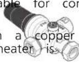
VPB 500 UK is a water heater, which is suitable for connection to heat pumps.
The water tank consists of a steel jacket, with a copper lining to protect against corrosion. The water heater is equipped with a copper nned tube.
The water heater is designed and manufactured for a maximum cut-o pressure of 6 bar in the water tank. Maximum permitted temperature is 90 °C.
The insulation is Neopor and polyester eece, which provides excellent heat insulation. The insulation and grey plastic outer cladding can be removed easily to simplify moving the water heater through doorways for example.


VPB 500 UK can be equipped with an immersion heater.
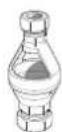
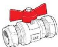
Shut o valve
Transport
VPB 500 UK should be transported and stored vertically in a dry place. The VPB 500 UK may, however, be carefully laid on its back when being moved into a building.
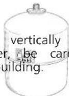


Expansion vessel with holder
Cold water inlet and expansion relief valve, water heater

Cover discs
Assembly
The water heater is only designed for upright iDstaihative with plug
The water heater's installation area should always a temperature of at least 10 °C (to prevent the damage from frost) and max 30 °C.
The water heater is unscrewed from the pallet into position, using the lifting eye at the top.
Position VPB 500 UK on a rm base that can weight, preferably on a concrete oor or found Use the product's adjustable feet to obtain a and stable set-up.


Plastic cover
The area where VPB 500 UK is located must with oor drainage.


Temperature limiter
Component positions
VPB 500 UK

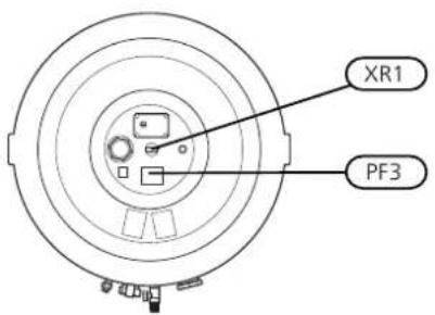
| NameDesignation | |
| Hot water sensor, top (factory tted)BT7 | |
| T&P valveFL5 | |
| Submerged tube, temperature limit, 10 mm (int)UA1 | |
| Submerged tube, docking heat pump (BT6), 11 mm (int)UA2 | |
| Submerged tube, external heat source (solar), 11 mm (int)UA3 | |
| Adjustable feetUL1 | |
| Lifting eyeXR1 | |
| Serial number platePF3 |
Removing the insulation
The insulation can be removed, to facilitate handling in confined spaces.
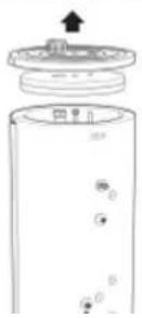
- Lift off the plastic top and the top insulation.
* On VPB 500, the lifting eye on the top must be unscrewed first. - Remove the joining plates holding the insulated jacket halves together. Do not use any tools when dismantling.
- Unhook and remove the insulated jacket halves, the outer diameter of the heater becomes approx. 200 mm less without the insulated jackets.
The figure shows VPB 500 UK with insulation. Do not use any tools when dismantling the joining plate.
∅850 mm with insulation

natural_image
Simple line drawing of a hand holding a small object, with no text or symbols present.Insulation removed
200 mm less without insulation

natural_image
Simple line drawing of a container with arrows indicating direction, no text or symbols presentCarry out assembly in reverse order.
Install the enclosed insulation plugs around each connection. Finally, t all the enclosed cover discs on each connection by pressing them over the connections.
NOTE
Fit the cover discs and the insulation plugs before installing the pipe.
NOTE
In certain cases, more insulation plugs are enclosed than are required.
Installation
VPB 500 UK can be equipped with the following elements, connection dimension G50. When installing the water heater, ensure that there is enough room in front of the connection area to remove the element, see following table.
Fit the enclosed cover discs before pipe installation. The cover discs, with self-adhesive backs, must be installed on the relevant connection, by pushing them over the connections.
All connections (including connections or holes left by the lifting eyes that are not used) must be insulated to minimise energy losses.
Immersion heaters
| Free | spaceOutput | ||||
| 250 | mm1500 | WIU | 31 | ||
| 260 | mm2250 | WIU | 33 | ||
| 280 | mm3000 | WIU | 34 | ||
Outline diagram

flowchart
graph TD
    A["External heat source (max 25 kW)"] --> B["QN17"]
    B --> C["RM1"]
    C --> D["QM30"]
    D --> E["FL1"]
    E --> F["FL5"]
    F --> G["FQ10"]
    G --> H["UA1"]
    H --> I["FL7"]
    I --> J["CM4"]
    J --> K["Ground"]
    L["CM5"] --> M["Ground"]
Explanation
Expansion vesselCM4 + CM5
Setting, expansion relief valveFL1
T&P-valveFL5
Shut o valveFL7
Temperature limiterFQ10
Shut o valve hot waterQM30
Pressure reducing valveQN17
Cold water inlet and pressure relief valve, water heaterRM1
Pocket tubeUA1
There's a plug on the cold water inlet valve that can be removed and there mount the exble hose for the expansion vessel CM4.
Pipe installation
General

NOTE
Pipe installation must be carried out in ance with current norms and directives


NOTE
This installation is subject to building approval, notify the local Authority of to install.
regulation intention

NOTE
Use only manufacturer's recommended replacement parts.
NOTE
Overow water from the safety valves goes via non-pressurised collecting pipes to a drain so that hot splashes cannot cause injury. These non-pressurised collecting pipes shall not be used for anything else. discharge pipe from the tundish connected to the ex sion relief valve (safety valve) shall also be connecte a drain in the same way.
The expansion vessel accommodates expansion
that results from heating the water inside the water. The expansion vessel must be connected between the expansion valve and the cylinder. The location of the expansion vessel should allow access to recharge the pressure as and when necessary.
Please note that the connection of the T&P-valve should not be used for any other purpose.
Valves may not be positioned between the expansion valve and the vessel.
Overow pipes from tundish must be routed with a fall and at least 300 mm long, before bends or angles in the pipework (see image).
The tundish should be installed away from electrical components.
| Valve outlet size | Minimum size of charge pipe | Minimum size of charge pipe from tundish | dMaximum resistance allowed, expressed as a lenght of straight pipe (i.e. elbows or bends) | Resistance created each elbow or be no |
| 0.8 mmup to 9 m22 mm15 | ||||
| 1.0 mmup to 18 m28 mm15 | ||||
| 1.4 mmup to 27 m35 mm15 | ||||
| 1.0 mmup to 9 m28 mm22 | ||||
| 1.4 mmup to 18 m35 mm22 | ||||
| 1.7 mmup to 27 m42 mm22 | ||||
| 1.4 mmup to 9 m35 mm28 | ||||
| 1.7 mmup to 18 m42 mm28 | ||||
| 2.3 mmup to 27 m54 mm28 |
The tables shows the dimension of the copper overow pipe for common safety valve connection size.
Hard water areas
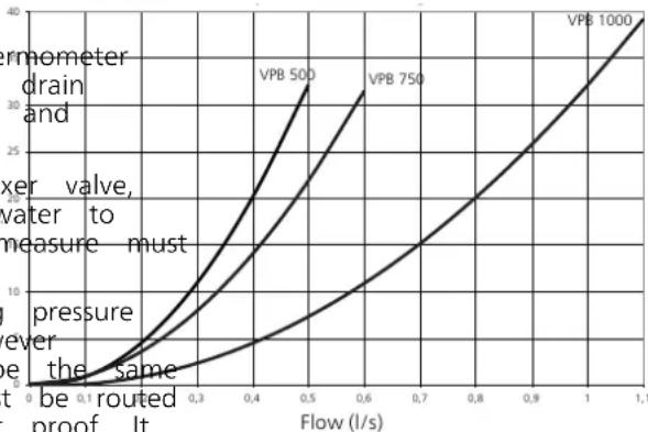
Pressure drop diagram
Usually, it should not be a problem installing VPB 500 UK
in areas of hard water as the operating temperature is Primary side (coil)
Pipe connection
The water heater must be supplied with and pressure gauge as well as a shut-o valve, non-return valve, mixer valve, safety vacuum valve as per applicable standards.
The water heater must be provided with which limits the temperature of outgoing 60 °C. If this valve is not tted, some be taken to prevent the risk of scalding
The safety valve must have a maximum opening in accordance to the applicable regulations (however max 6 bar/0.6 MPa). The overflow pipe must be size as the safety valve. The overflow pipe must downwards along its entire length and be frost must run out unobstructed over the drain.
Pressure drop (kPa)
line
| Flow (l/s) | VPB 500 | VPB 750 | VPB 1000 | | ---------- | ------- | ------- | -------- | | 0.1 | ~2 | ~3 | ~4 | | 0.3 | ~8 | ~12 | ~16 | | 0.5 | ~16 | ~24 | ~30 | | 0.7 | ~24 | ~36 | ~48 | | 1.0 | ~32 | ~48 | ~68 | | 1.1 | ~40 | ~60 | ~88 |Commissioning and adjusting
Filling the water heater
Fill as follows:
- Open a hot water tap in the system.
- Open the shut-o valve on the incoming cold water. This valve should then be fully open during operation.
- The hot water tap can only be shut o when the water heater is lled, which is when only water comes out of the tap (initially an air-water mixture comes out of the tap).
Cleaning the climate system
When the water heater and the climate system have been lled with water, VPB 500 UK must operate at maximum normal temperature for at least one hour. Thereafter the system must be drained of water and re-
Emptying the system by
- Open external ller valve and external drain valve.
- Flush the system for some minute. Watch out for water splashes from the safety valve.
- Close the valves and check the stainer.
Electrical installation

NOTE
Electrical installation and service must be out under the supervision of a qualified cian, and in accordance with applicable safety regulations.
VPB 500 UK can be supplemented with an immersion heater with a maximum output of 3 kW.
The immersion heater is supplemented with junction box type K11 (2-pole thermostat, 3-pole temperature limiter). Do not modify or reconnect!
A separate supply from group central is routed to the immersion heater.
Sensors
VPB 500 UK can be supplemented with one hot water sensor, for display and control. The sensor is positioned in the pocket tube for the sensor (UA2).
Use the sensors provided with the heat pump/control module. When no heat sensors have been provided these must be ordered from the manufacturer of the heat pump/ control module.
Temperatur limiter
Power supply to temperature limiter (FQ10) is 230 V. Connect temperature limiter electrically to the solenoid carried for the heat source.
electri the sensor in the pocket tube (UA1). electrical

Connection temperature limiter


NOTE
The water heater must be completely filled with water before it is connected on the electrical side.
4 Technical data
Dimensions

Pipe connections
VPB 500 UK
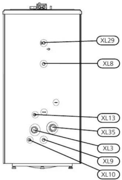

| DimensionsName | ||
| G50Cold water connection | ||
| G50Hot water connection | ||
| ∅ 15 mmHWC connection | ||
| ∅ 28 mmDocking connection | ||
| ∅ 28 mmDocking connection | ||
| ∅ 22 mmDrain connection | ||
| ∅ 22 mmOther heat source | ||
| ∅ 15 mmConnection T&P | ||
| XL35G50Connection for imme |
*can be used as an access to view the cylinder internally.
Technical specifications
| VPB 500 UKMode | ||
| CopperCorrosion protection | ||
| 850mmDiameter (excl. feet) | ||
| 1757mmHeight weight | ||
| 212kgGross weight | ||
| 170kgNet weight heater, sup | ||
| 230VImmersion | ||
| 3kWMax. output | ||
| kWTotal input power | ||
| kWDrainage capacity T&P valve | ||
| Max pressure incoming cold water | bar/MPa | 16/1.6 |
| Pressure reduction valve, setting: | bar/MPa | 3.5/0.35 |
| Max pressure, water heater | bar/MPa | 6/0.6 |
| Max pressure, primary side | bar/MPa | 3/0.3 |
| Operating pressure, secondary side | bar/MPa | 5.5/0.55 |
| Setting, expansion relief valve | bar/MPa | 6/0.6 |
| Max operating pressure, T&P-valve | bar/MPa | 7/0.7 |
| Exp. vessle, tap water, charge pressure | bar/MPa | 3.5/0.35 |
| Max operating temperature, T&P-valve | °C | 90 |
| Maximum operating temperature, heating uid: | °C | 90 |
| 490litreVolume, hot water coil | ||
| 6litreVolume, coil | ||
| Length, coil | 15.7m | |
| Heating surface, coil | m^2 | 5.2 |
| 15.8kWHeat transfer, primal | ||
| Heat content at 50°C | kWh | 23 |
| 825litreEquivalent amount | ||
| Heating time to 15 - 60 °C, (10 kW)** | min. | 163 |
| Part No. | 081 056 | |
* At incoming temperatures 10 °C and hot water draining of 30 l/min.
** Primary ow to achieve the maximum capacity VPB 500 UK: 2000 l/h.
Tested according to En 12897:2016
Energy labelling
| NIBESupplier | ||
| Model | VPB 500 UK | |
| Energy eciency class | C | |
| Heat loss | W | 111 |
| Volume | I | 496 |
Accessories
Immersion heater IU
Immersion heater IU 31 - IU34
See table (page 12)
Connection box K11
Connection box with thermostat and overheating protection. (When connecting Immersion heater IU)
Part no. 018 893
5 Item register
Item register
A
Accessories, 19
D
Dimensions, 17
|
Important information, 4
Safety information, 4
Inspection of the installation, 6
M
Marking, 4
P
Pipe connections
Cleaning the climate system, 15
Hard water areas, 15
5
Safety information, 4
Inspection of the installation, 6
Marking, 4
Symbols on VPB 500 UK, 4
Warranty information, 5
Symbols on VPB 500 UK, 4
T
Technical data
Dimensions, 17
W
Warranty information, 5
MAINS PRESSURE HOT WATER STORAGE SYSTEM COMMISSIONING CHECKLIST
This Commissioning Checklist is to be completed in full by the competent person who commissioned the storage system as a means of demonstrating compliance with the appropriate Building Regulations and then handed to the customer to keep for future reference.
Failure to install and commission this equipment to the manufacturer's instructions may invalidate the warranty but does not affect statutory rights.
Customer Name ____ Telephone Number ____
Address
Cylinder Make and Model ____
Cylinder Serial Number
Commissioned by (print name) ____ Registered Operative ID Number ____
Company Name ____ Telephone Number ____
Company Address ____
Commissioning Date
To be completed by the customer on receipt of a Building Regulations Compliance Certificate*:
Building Regulations Notification Number (if applicable)
ALL SYSTEMS PRIMARY SETTINGS (indirect heating only)
| Is the primary circuit a sealed or open vented system? Sealed | Open | |
| What is the maximum primary flow temperature? | °C |
ALL SYSTEMS
| What is the incoming static cold water pressure at the inlet to the system? | bar | |||
| Has a strainer been cleaned of installation debris (if fitted)? Yes | ☐ | No | ||
| Is the installation in a hard water area (above 200ppm)? Yes | ☐ | No | ||
| If yes, has a water scale reducer been fitted? | Yes | ☐ | No | |
| What type of scale reducer has been fitted? | ||||
| What is the hot water thermostat set temperature? | °C | |||
| What is the maximum hot water flow rate at set thermostat temperature (measured at high flow outlet)? | l/min | |||
| Time and temperature controls have been fitted in compliance with Part L of the Building Regulations? | Yes | |||
| Type of control system (if applicable) Y Plan | ☐ | S Plan ☐ | Other | |
| Is the cylinder solar (or other renewable) compatible? | Yes | ☐ | No | |
| What is the hot water temperature at the nearest outlet? | °C | |||
| All appropriate pipes have been insulated up to 1 metre or the point where they become concealed | Yes | |||
| Where is the pressure reducing valve situated (if fitted)? | ||
| What is the pressure reducing valve setting? | bar | |
| Has a combined temperature and pressure relief valve and expansion valve been fitted and discharge tested? | Yes □ | No □ |
| The tundish and discharge pipework have been connected and terminated to Part G of the Building Regulations | Yes □ | |
| Are all energy sources fitted with a cut out device? | Yes □ | No □ |
| Has the expansion vessel or internal air space been checked? | Yes □ | No □ |
THERMAL STORES ONLY
| What store temperature is achievable? | °C | |
| What is the maximum hot water temperature? | °C |
ALL INSTALLATIONS
| The hot water system complies with the appropriate Building Regulations | Yes | |
| The system has been installed and commissioned in accordance with the manufacturer's instructions | Yes | |
| The system controls have been demonstrated to and understood by the customer | Yes | |
| The manufacturer's literature, including Benchmark Checklist and Service Record, has been explained and left with the customer | Yes |
Commissioning Engineer's Signature
Customer's Signature
(To confirm satisfactory demonstration and receipt of manufacturer's literature)
*All installations in England and Wales must be notified to Local Authority Building Control (LABC) either directly or through a Competent Persons Scheme.
A Building Regulations Compliance Certificate will then be issued to the customer.
SERVICE RECORD
It is recommended that your hot water system is serviced regularly and that the appropriate Service Record is completed.
Service Provider
Before completing the appropriate Service Record below, please ensure you have carried out the service as described in the manufacturer's instructions.
SERVICE 1 Date
Engineer Name
Company Name
Telephone Number
Comments
Signature
SERVICE 2 Date
Engineer Name
Company Name
Telephone Number
Comments
Signature
SERVICE 3 Date
Engineer Name
Company Name
Telephone Number
Comments
Signature
SERVICE 4 Date
Engineer Name
Company Name
Telephone Number
Comments
Signature
SERVICE 5 Date
Engineer Name
Company Name
Telephone Number
Comments
Signature
SERVICE 6 Date
Engineer Name
Company Name
Telephone Number
Comments
Signature
SERVICE 7 Date
Engineer Name
Company Name
Telephone Number
Comments
Signature
SERVICE 8 Date
Engineer Name
Company Name
Telephone Number
Comments
Signature
SERVICE 9 Date
Engineer Name
Company Name
Telephone Number
Comments
SERVICE 10 Date
Engineer Name
Company Name
Telephone Number
Comments
Signature
Signature
NIBE Energy Systems Ltd
3C Broom Business Park
Bridge Way
Chesterfield S41 9QG
Phone 0845 095 1200
Fax 0845 095 1201
info @nibe.co.uk
www.nibe.co.uk

331976



- Table of Contents
- Important information
- Safety information
- General
- cedures Serial number
- Recovery
- Country specific information
- User and Installer manual
- Great Britain
- Symbols
- NOTE
- Caution
- TIP
- Marking
- Warranty and insurance information
- Inspection of the installation
- For the User
- Maintenance
- Safety valve
- Emptying
- Service
- For the Installer
- Supplied components
- Transport
- Assembly
- Component positions
- Removing the insulation
- Installation
- Outline diagram
- Explanation
- Pipe installation
- Hard water areas
- Pressure drop diagram
- Pipe connection
- Commissioning and adjusting
- Filling the water heater
- Cleaning the climate system
- Electrical installation
- Sensors
- Temperatur limiter
- Connection temperature limiter
- Technical data
- Pipe connections
- Accessories
- Immersion heater IU
- Connection box K11
- Item register
- Item register
- A
- D
- |
- M
- P
- 5
- T
- W
- MAINS PRESSURE HOT WATER STORAGE SYSTEM COMMISSIONING CHECKLIST
- SERVICE RECORD
- Service Provider
- SERVICE 1 Date
- SERVICE 2 Date
- SERVICE 3 Date
- SERVICE 4 Date
- SERVICE 5 Date
- SERVICE 6 Date
- SERVICE 7 Date
- SERVICE 8 Date
- SERVICE 9 Date
- SERVICE 10 Date
Brand : Nibe
Model : VPB 500-1000
Category : Water heaters and boilers