
S125MW1E5 - Heat pump PANASONIC - Free user manual and instructions
Find the device manual for free S125MW1E5 PANASONIC in PDF.

| Brand | PANASONIC |
| Model | S125MW1E5 |
| Product type | Commercial hydraulic heat pump |
| Refrigerant | R410A |
| Global warming potential (GWP) | 1975 |
| Outdoor temperature range (cooling) | -10°C to 46°C (dry bulb) |
| Outdoor temperature range (heating) | -20°C to 35°C (wet bulb) |
| Water temperature range (cooling) | 5°C to 20°C (or 14°C to 25°C depending on mode) |
| Water temperature range (heating) | 25°C to 45°C (or 15°C to 30°C depending on mode) |
| Main functions | Tank mode, air conditioning mode, anti-legionella sterilization, heat curve, forced internal heating |
| Operating modes | Cooling, heating, automatic (via remote control) |
| Remote control | High-end wired remote control (CZ-RTC5 optional) |
| Safety | Key lock, fault detection, automatic stop in case of anomaly, freeze protection |
| Maintenance and cleaning | Exterior cleaning only; call a professional for the interior |
| Troubleshooting | Error codes (E03, E04, F01, etc.); contact the dealer if persistent |
| Spare parts and repairability | Do not repair yourself; contact an authorized dealer |
| Installation | Installation by a qualified professional; dedicated power supply and grounding |
| Energy consumption | Energy saving function; use curtains in cooling mode |
| General information | Manual available in several languages; average lifespan 10-15 years |
| Warranty | Consult the dealer |
Frequently Asked Questions - S125MW1E5 PANASONIC
User questions about S125MW1E5 PANASONIC
0 question about this device. Answer the ones you know or ask your own.
Ask a new question about this device
Download the instructions for your Heat pump in PDF format for free! Find your manual S125MW1E5 - PANASONIC and take your electronic device back in hand. On this page are published all the documents necessary for the use of your device. S125MW1E5 by PANASONIC.
USER MANUAL S125MW1E5 PANASONIC
natural_image
Front view of a Panasonic industrial control panel with a central valve and base mount (no text or symbols on the panel itself)Model No.
INDOOR UNIT
Air-to-Water Heatpump
(Type W1)
S-80MW1E5
S-125MW1E5
- Connectable outdoor unit lineup This booklet is the operating instructions for indoor unit. Regarding the outdoor unit, see the operating instructions supplied with the outdoor unit.
OUTDOOR UNIT
3WAY VRF (Type MF2)

ENGLISH
2 \~ 13
Before operating the unit, read these operating instructions thoroughly and keep them for future reference.
FRANÇAIS
14 \~ 25
Thank you for purchasing this Panasonic product. This product is a commercial Air-to-Water unit. Installation Instructions attached.
Be sure to read the operating instructions relevant to the VRF system connected to this Air-to-Water and all appliances connected to the VRF system.
Contents
● Safety Precautions....2
● Precautions for Use 4
- Names of Parts....5
- Initial Settings ...... 7
Operation 8
• Operation Mechanism 9
● Function of Air-to-Water Unit....10
● Maintenance 12
- Before Requesting Services....12
● Troubleshooting....13
Specifications.... 122
- Indoor unit 122
- Corresponding language table.... 122
Product Information
If you have problems or questions concerning your Air-to-Water, you will need the following information. Model and serial numbers are on the nameplate on the lid of the electrical component box.
Model No.
Serial No.
Date of purchase
Dealer's address
Phone number
Safety Precautions
The following symbols used in this manual, alert you to potentially dangerous conditions to users, service personnel or the appliance:

WARNING
This symbol refers to a hazard or unsafe practice which can result in severe personal injury or death.

CAUTION
This symbol refers to a hazard or unsafe practice which can result in personal injury or product or property damage.

Prohibited matters

Matters to be observed
- Read these Operating Instructions carefully before using this Air-to-Water. If you still have any difficulties or problems, consult your dealer for help.
- This Air-to-Water is designed to give you comfortable room conditions. Use this only for its intended purpose as described in these Operating Instructions.
WARNING

Confirm to authorized dealer or specialist on usage of specified refrigerant type. Using of refrigerant other than the specified type may cause product damage, burst and injury etc.
This Air-to-Water has no ventilator for intaking fresh air from outdoors. You must open doors or windows frequently when you use gas or oil heating appliances in the same room, which consume a lot of oxygen from the air. Otherwise there is a risk of suffocation in an extreme case.

Never use or store gasoline or other flammable vapor or liquid near the Air-to-Water — it is very dangerous.
Do not use this appliance in a potentially explosive atmosphere. Never touch the unit with wet hands.
Do not insert your fingers or other objects into the Air-to-Water indoor or outdoor unit, rotating parts may cause injury.


If the refrigerant comes in contact with a flame, it produces a toxic gas.
For safety, be sure to turn the Air-to-Water off and also to disconnect the power before cleaning or servicing.
Pull off the power plug from a receptacle, or switch off the breaker, or switch off the power disconnecting mean to isolate the Air-to-Water from the main power supply in case of emergency.

Do not clean inside the indoor and outdoor units by users. Engage authorized dealer or specialist for cleaning.
In case of malfunction of this appliance, do not repair by yourself. Contact to the sales dealer or service dealer for a repair.

Provide a power outlet to be used exclusively for each unit, and a power supply disconnect, Earth Leakage Circuit Breaker (ELCB) or Residual Current Device (RCD) for overcurrent protection should be provided in the exclusive line.
Provide a power outlet exclusively for each unit, and full disconnection means having a contact separation in all poles must be incorporated in the fixed wiring in accordance with the wiring rules.
To prevent possible hazards from insulation failure, the unit must be grounded.


Do not use modified cord, joint cord, extension cord or unspecified cord to p overheating and fire.


Stop using the product when any abnormality/failure occurs and disconnect the power plug or turn off the power switch and breaker. (Risk of smoke/fire/electric shock) Examples of abnormality/failure:
• The ELCB trips frequently.
- The product sometimes does not start when turned on.
- The power is sometimes disconnected when the cord is moved.
- Burnt odor or abnormal noise is detected during operation.
• The body is deformed or abnormally hot.
• Water leaks from the indoor unit.
- Power cord or plug becomes abnormally hot.
- Fan speed cannot be controlled.
- The unit stops running immediately even if it is switched on for operation.
- The fan does not stop even if the operation is stopped.
Contact immediately your local dealer for maintenance/repair.
CAUTION

This appliance is intended to be used by expert or trained users in shops, in light industry and on farms, or for commercial use by lay persons.
This appliance can be used by children aged from 8 years and above and persons with reduced physical, sensory or mental capabilities or lack of experience and knowledge if they have been given supervision or instruction concerning use of the appliance in a safe way and understand the hazards involved.
Keep the fire alarm and the air outlet at least 1.5m away from the unit.
Do not cool or heat the room too much if babies or invalids are present.

Do not turn the Air-to-Water on and off from the power mains switch. Use the ON/OFF operation button.
Do not stick anything into the air outlet of the outdoor unit. This is dangerous because the fan is rotating at high speed.

Do not touch the air inlet or the sharp aluminum fins of the outdoor unit. You may get injured.

Do not sit or step on the unit. You may fall down accidentally.

Do not stick any object into the FAN CASE. You may be injured and the unit may be damaged.


NOTICE
- The compressor may occasionally stop during thunderstorms. This is not a mechanical failure. The unit automatically recovers after a few minutes.
- The English text is the original instructions. Other languages are translation of the original instructions.
Important Information Regarding The Refrigerant Used
This product contains fluorinated greenhouse gases covered by the Kyoto Protocol. Do not vent gases into the atmosphere.
Refrigerant type: R410A
GWP ^(1) value: 1975
^(1) GWP = global warming potential
Periodical inspections for refrigerant leaks may be required depending on European or local legislation. Please contact your local dealer for more information.
Precautions for Use
Installation
- This Air-to-Water must be installed properly by qualified installation technicians in accordance with the Installation Instructions provided with the unit.
- Before installation, check that the voltage of the electric supply in your home or office is the same as the voltage shown on the nameplate.
WARNING
Avoid the following locations for installation.
- Locations where smoke or combustible gas exists. Also locations of extremely high temperature such as a greenhouse.
- Locations where excessively high heat-generating objects are placed.
Attention:
- Avoid installing the outdoor unit where salty sea water can splash directly onto it or in sulphurous air near a spa. (To protect the Air-to-Water from heavy corrosion)
Wiring
● All wiring must conform to the local electrical codes. (Consult your dealer or a qualified electrician for details.)
● Each unit must be properly grounded with a ground (or earth) wire or through the supply wiring.
● Wiring must be done by a qualified electrician.
Operation Preparation
Turn the power mains on 5 hours before the start of operation.
(For warm-up)
- Leave the power mains ON for continuous use.
NOTE
Pull off the power plug from a receptacle, or switch off the breaker, or switch off the power disconnecting mean to isolate the Air-to-Water from the main power supply when not in use for a long time.
Tips for Energy Saving
Avoid
- Do not block the air intake and outlet or water intake and outlet of the unit. (If either is obstructed, the unit will not function well, causing malfunction.)
- During cooling operation, use sunshades, blinds or curtains to prevent direct sunlight from entering the room.
Do
● Always keep the water clean.
(A luck of water flow will impair the performance of the unit.)
→ “Maintenance” (P.12)
- To prevent conditioned air from escaping, keep windows, doors and any other openings closed.
Operation Condition
Use this Air-to-Water under the following temperature range.
| Outdoor Unit | Indoor (water) temperature range | Outdoor temperature range | |
| 3WAY (Type MF2) | |||
| Cooling*1 | 14°C ~ 25°C(5°C ~ 20°C) | -10°C ~ 46°C (*DBT) | |
| Heating | 15°C ~ 30°C(25°C ~ 45°C)*2 | -20°C ~ 35°C (*WBT) | |
| Cooling & Heating | — | -10°C ~ 35°C (*DBT) | |
*DBT: Dry bulb temperature *WBT: Wet bulb temperature
*1: Make sure to install the 2-way Valve in case that radiator/ floor heater is installed in the cooling circuit. If dew is condensed on the radiator/floor heater at defrosting operation, turn on the Air-to-Water in heating mode to prevent condensation.
*2: When the water temperature is less than 25^ , preheat the water over 25^ (operate only Air-to-Water unit).
Information for Users on Collection and Disposal of Old Equipment and Used Batteries
These symbols on the products, packaging, and/or accompanying documents mean that used electrical and electronic products and batteries should not be mixed with general household waste.
For proper treatment, recovery and recycling of old products and used batteries, please take them to applicable collection points, in accordance with your national legislation and the Directives 2002/96/EC and 2006/66/EC.
By disposing of these products and batteries correctly, you will help to save valuable resources and prevent any potential negative effects on human health and the environment which could otherwise arise from inappropriate waste handling.
For more information about collection and recycling of old products and batteries, please contact your local municipality, your waste disposal service or the point of sale where you purchased the items.
Penalties may be applicable for incorrect disposal of this waste, in accordance with national legislation.
For business users in the European Union
If you wish to discard electrical and electronic equipment, please contact your dealer or supplier for further information.
[Information on Disposal in other Countries outside the European Union]
These symbols are only valid in the European Union. If you wish to discard these items, please contact your local authorities or dealer and ask for the correct method of disposal.
![PANASONIC S125MW1E5 - [Information on Disposal in other Countries outside the European Union] - 1](/content/2019/08/105595/images/ca799e9c1df95af0861b5b703bdb0b251226ec026e935f2d2bd47dca7c51cab0.jpg)
Note for the battery symbol (bottom two symbol examples):
This symbol might be used in combination with a chemical symbol. In this case it complies with the requirement set by the Directive for the chemical involved.
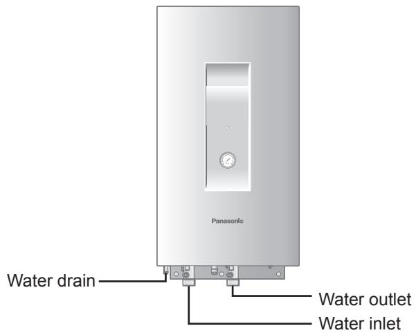
Names of Parts
INDOOR UNIT
ENGLISH
High-spec Wired Remote Controller (Optional: Model No. CZ-RTC5)
Return button
Returns to the previous screen.
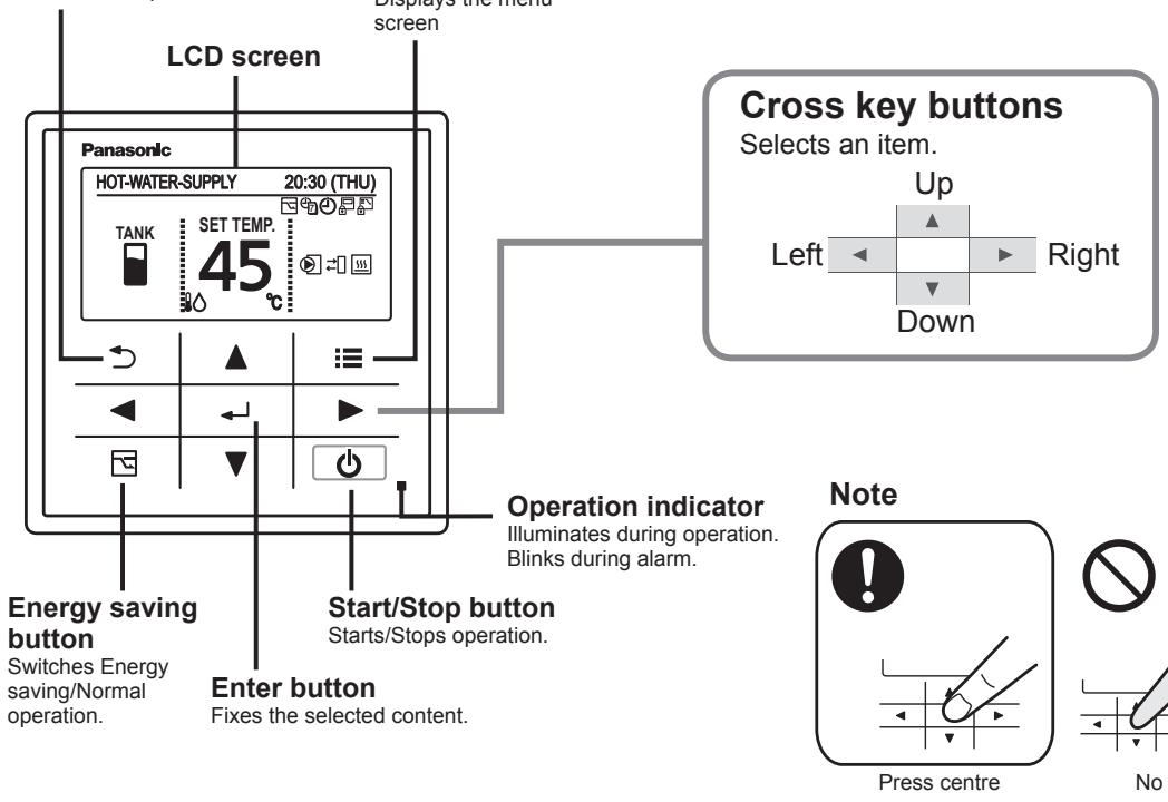
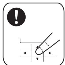
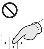
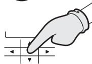
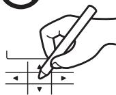
No glove

No pen
Menu screen
![Screen name Present time & day Menu 20:30 (THU) 1. Basic instructions 2. FLAP 3. Lock indiv. flap 4. ON/OFF timer ▼ Sel. ▶ Page [ ← ] Confirm Operation guide The currently operable content is simply displayed. • ▲▼◀▶ : Cross key buttons • ← : Enter button](/content/2019/08/105595/images/259f07eadd59462fd6f2f2eb2e1389e59c981e951ea8a0af7fa74ee2901e7c2f.jpg)
Names of Parts
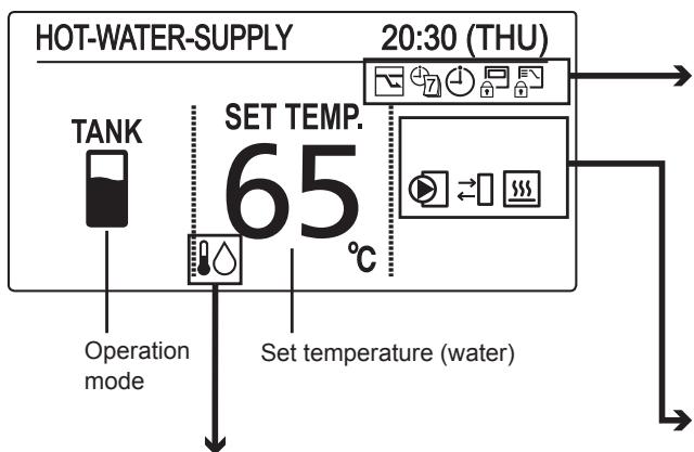
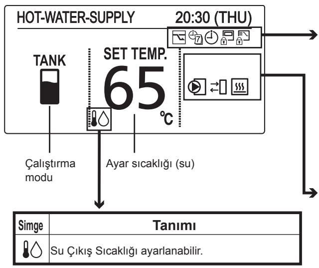
TANK mode
flowchart
graph TD
    A["HOT-WATER-SUPPLY"] --> B["TANK"]
    B --> C["SET TEMP. 65°C"]
    C --> D["20:30 (THU)"]
    D --> E["Operation mode"]
    C --> F["Set temperature (water)"]
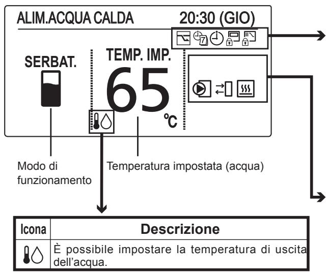
| Icon | Description |
| It is able to set Water Out Temperature. |
■ Setting information icons displayed on the top screen
| Icon | Description |
| Switching operation modes is prohibited.(Switching to Auto mode is also prohibited.) | |
| Remote control operation is restricted by a central control device. | |
| [ON/OFF timer] is set. | |
| [Weekly timer] is set. | |
| Energy saving operation is in process. |
| Icon | Description |
| Internal heater is active. | |
| Internal heater is abnormal. | |
| Internal heater is manually in process. | |
| Internal heater is not in process. | |
| Control to prevent water freezing is active. | |
| External device ready demand*1 | |
| External device notice*2 | |
| External pump is active. | |
| Water is under sterilization. |
*1 When the heat capacity for Air-to-Water is insufficient, output signal is sent to the external device.
*2 When the notice is input from the external device, the icon appears on the wired remote controller.
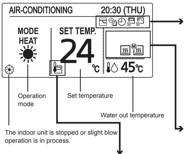
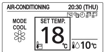
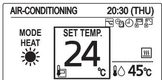
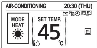
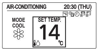
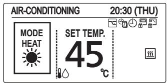
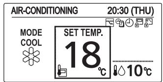
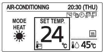
Air-Conditioning mode
flowchart
graph TD
    A["AIR-CONDITIONING"] --> B["MODE HEAT"]
    B --> C["SET TEMP. 24°C"]
    C --> D["20:30 (THU)"]
    D --> E["Water out temperature"]
    E --> F["The indoor unit is stopped or slight blow operation is in process."]
    style A fill:#f9f,stroke:#333
    style B fill:#ccf,stroke:#333
    style C fill:#cfc,stroke:#333
    style D fill:#fcc,stroke:#333
    style E fill:#cff,stroke:#333
| Icon | Description |
| It is able to set Water Out Temperature. | |
| It is able to set Room Temperature from thermo sensor (RC thermo or remote sensor thermo). | |
| Thermo sensor (RC thermo or remote sensor thermo) is abnormal. | |
| It is able to set Offset value of Heating Curve Function. (only heating mode) |
■ Setting information icons displayed on the top screen
| Icon | Description |
| Switching operation modes is prohibited.(Switching to Auto mode is also prohibited.) | |
| Remote control operation is restricted by a central control device. | |
| [ON/OFF timer] is set. | |
| [Weekly timer] is set. | |
| Energy saving operation is in process. |
| Icon | Description |
| Internal heater is active. | |
| Internal heater is abnormal. | |
| Internal heater is manually in process. | |
| Internal heater is not in process. | |
| Control to prevent water freezing is active. | |
| External pump is active. |
Initial Settings
Clock
■ Clock type
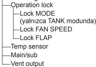
Operation lock
When applying a power on for the first time, it is necessary to initialize the remote controller for Air-to-Water unit. Please refer to the installation instructions or consult the contractor.
1 Display the menu screen.

■ To return to the previous screen
Press ↻.
■ To return to the top screen
Press ≡ 2 times.
![Menu 20:30 (THU) 1. Basic instructions 2. FLAP 3. Lock indiv. flap 4. ON/OFF timer ✓ Sel. ▶ Page [ ] Confirm](/content/2019/08/105595/images/8e28ccc916aba310aa4d4a24383aab294da9763c417486b8ce3e4b72d88fc79c.jpg)
2 Select [Initial settings].
![PANASONIC S125MW1E5 - Select [Initial settings]. - 1](/content/2019/08/105595/images/5c68b319860fad3dd36ab412d729c8b75962b2f1bf32c17cd46236f29c625c5f.jpg)
![Menu 20:30 (THU) 8. Quiet operation 9. Power consumption monitor 10. Energy saving 11. Initial settings ◀ Sel. ◀ ▶ Page [←] Confirm](/content/2019/08/105595/images/a85cf8b2584010e4607e33f1806ea6c137afe7248ddfbd955e963408a52b566e.jpg)
3 Select the item to set.
![Initial settings 20:30 (THU) 1. Clock 2. Clock type 3. Controller name 4. Operation lock ▼ Sel. ▶ Page [ ← ] Confirm](/content/2019/08/105595/images/bef9f7a271929b1d1e15b83a4ba051c133216ee2e4bb00e59c677a903991001d.jpg)
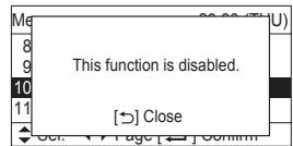
* The Air-to-Water function is not applicable to the feature list No.2, No.3, No.6, No.7, No.10, No.11 and No.12 at the Menu screen (in TANK mode and Air-Conditioning mode).
- FLAP
- Lock indiv. flap
- Filter info
- Outing function
- Energy saving
- Initial settings
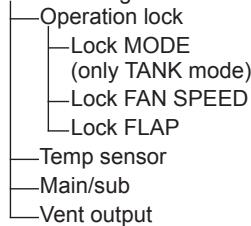
flowchart
graph TD
    A["Operation lock"] --> B["Lock MODE (only TANK mode)"]
    B --> C["Lock FAN SPEED"]
    C --> D["Lock FLAP"]
    E["Temp sensor"] --> F["Main/sub"]
    G["Vent output"] --> H["End"]
- Ventilation
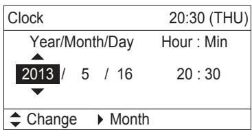
Clock
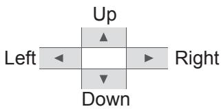
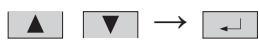
4 Set the date and time.
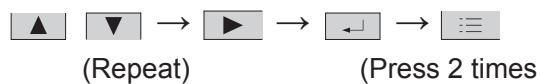
flowchart
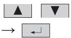
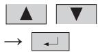
graph LR
    A["▲"] --> B["▼"]
    B --> C["▶"]
    C --> D["←"]
    D --> E["≡"]
    style A fill:#fff,stroke:#000
    style B fill:#fff,stroke:#000
    style C fill:#fff,stroke:#000
    style D fill:#fff,stroke:#000
    style E fill:#fff,stroke:#000
    note1[" (Repeat) "]
    note2[" (Press 2 times ) "]

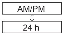
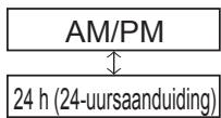
Clock type
4 Select the type to display.

(Press 2 times to finish.)
![Clock type 8:30PM (THU) AM/PM ◆ Change [ ← ] Confirm](/content/2019/08/105595/images/0a0da59d526124fae91406c2af9817188116eef3d73ae592cdcf338da080115e.jpg)
Operation lock
4 Select the type of lock and set to


(Press 2 times to finish.)
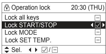
■ To cancel lock
Select [-] in step 4.
■ Only for [Lock all keys]
Select [YES].

![Lock all keys? Hold [→] for 4 s. to unlock YES NO](/content/2019/08/105595/images/83ceac7d42b031fad47d87b7b9ad77747279aa979995192fc813086a2977e5c6.jpg)

TANK mode
1 Start Operation
Press
(The operation indicator illuminates.)
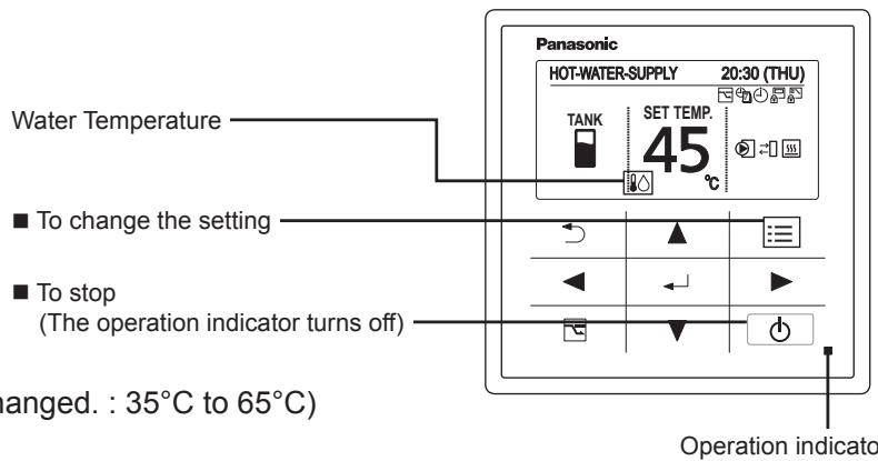
2 Change the temperature setting
Press ▲ ▼
(In TANK mode, only "SET TEMP." can be changed.: 35°C to 65°C)
(The cursor disappears.)
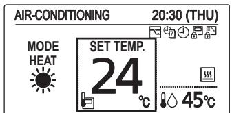
Air-Conditioning mode
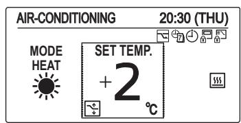
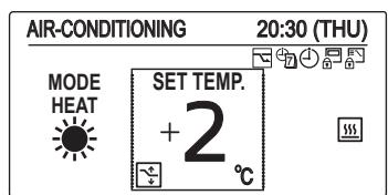
[Heating Curve Function] (Only heating mode)
Supply water temperature is adjusted automatically, according to outdoor temperature.
Supply water temperature is able to adjust manually by changing offset value.
■ Case: With use of Heating Curve Function.
1 Start Operation
Press
(The operation indicator illuminates.)
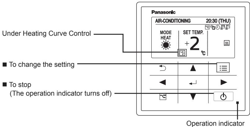
2 Change the setting
Press ▲ ▼
- Set temperature
Press
(When the cursor is not visible.)
Heat (With use of Heating Curve) : -5°C to +5°C (offset)
For cooling, see the note [Normal mode] below.
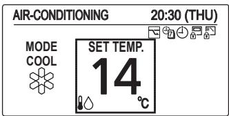
[Normal mode] With no use of Heating Curve Function.
Supply water temperature can be set.
■ Case: With no use of Heating Curve Function.
1 Start Operation
Press
(The operation indicator illuminates.)
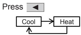
2 Select the item to set
Press ◀ ▶
3 Change the setting
Press ▲ ▼
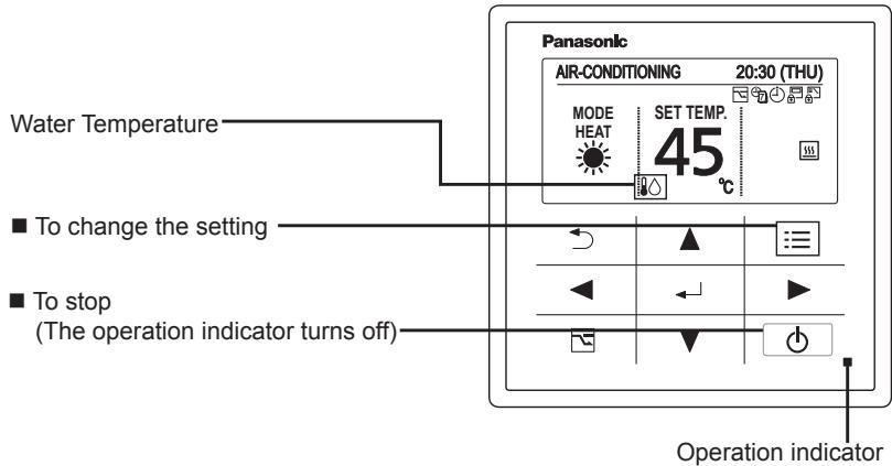
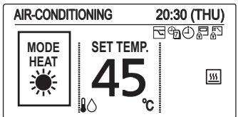
● Operation mode (e.g. Cool, Heat)

- Set temperature
Press
(When the cursor is not visible.)
Water temperature
Cool : 5°C to 20°C
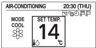
Heat (With no use of Heating Curve) : 25°C to 45°C
Room temperature (With use of remote controller thermo)
Cool : 18°C to 30°C
Heat : 16°C to 30°C
NOTE
- Group control function cannot be used for the Air-to-Water unit.
Be sure to confirm the individual remote controller connection is used for each Air-to-Water unit.
- If your heating appliance is a radiator or floor heating, dew may be condensed on the appliance during defrosting operation.
In that case, turn on the Air-to-Water in heating mode to prevent condensation.
Operation Mechanism
■ Heating Performance
- Since this Air-to-Water utilizes outside air for heating, its heating performance deteriorates as outdoor temperature decreases. (Due to heat pump system) Information called “External device ready demand” is outputted from terminal of electrical component box.
Use another heating appliance using this information, etc.
- It will take some time until the supplied water temperature becomes warmer after heating operation started.
■ Defrosting
- This appliance may start defrosting operation to melt frost form in the outdoor unit during long hour heating operation mode.
The indoor unit including Air-to-Water will stop for about 5 to 10 minutes at this time.
■ Heating Standby
The remote controller shows “⚙️” (Heating standby) on the display in the following mode and heating capacity will be limited.
- When operation started
- When Thermostat activated
- When defrosting
■ When Heating Operation Started (Only 3WAY VRF)
When changed to heating mode from stopped or cooling operation mode, the unit does not work for about 3 minutes for the sake of self-protection.
It may take about 5 to 10 minutes until the hot water is delivered after starting the heating operation.
Oil Recovery
The water pump may run at a slow speed in order to recover the oil in the system every 1 to 3 hours during cooling or heating operation.
The unit will automatically resume the original operation after about 5 to 10 minutes.
■ Remote Control Sensor
The temperature sensor in the Air-to-Water normally senses the water temperature and can also sense the ambient temperature of the remote controller. (room temperature) For the details, consult the shop you purchased.
■ Should the power failure occurs while the unit is running
When the unit automatically resumes operation after temporary power failure, it uses the same settings before the power was cut off.
Function of Air-to-Water Unit
![Menu 20:30 (THU) 1. Basic instructions 2. FLAP 3. Lock indiv. flap 4. ON/OFF timer ✓ Sel. ▶ Page [ ] Confirm](/content/2019/08/105595/images/76e9fd2f75e41e9a210b11b7b15c73f40bdc51dfd7b14a4d142834e74bf59e18.jpg)
1 Display the menu screen.

- TANK mode
![Air-to-Water unit 20:30 (THU) Sterilization timer Stop sterilization Int.heater forced ON ▼ Sel. ▶ ▶ / [←] Set](/content/2019/08/105595/images/62b3920865414a33fa2562f85d594a2e7162b535fbd61286fcf5db535ccd7af0.jpg)
3 Select the item to set.
![Menu 20:30 (THU) 11. Initial settings 12. Ventilation 13. Setting list 14. Air-to-Water unit ▲ Sel. ← Page [←] Confirm](/content/2019/08/105595/images/d1e199aacaeedcb9868ef88f648e0be69f919276bf51ac03c3fc10af83e6422e.jpg)
2 Select
[14. Air-to-Water unit].


• Air-Conditioning mode
TANK mode
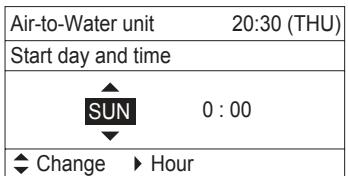
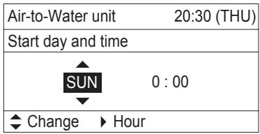
■ Sterilization timer
To prevent propagation of legionella bacterium in the tank, it is able to perform sterilization process once a week. While the sterilization process is performed, 🚙️ icon appears.
- Timer Setting
![Air-to-Water unit 20:30 (THU) Sterilization timer Stop sterilization Int.heater forced ON ✓ Sel. ✓ / [←] Set Air-to-Water unit 20:30 (THU) Start day and time SUN 0 : 00 ✓ Change ▶ Hour](/content/2019/08/105595/images/07c9de251041b4e287319dddce553f48c8b7c2cf6da4cd837714f5cbb2f926fc.jpg)
If “Sterilization timer” is enabled ☑, the screen is switched to set the day of the week and time for sterilization process.
Set the day of the week and time for sterilization process.
Select the item by ◀ ▶ button and decide by ▲ ▼ button.
• Under Sterilization process
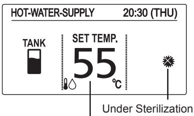
Target water out temperature for sterilization (If the set temperature is higher than temperature for sterilization, the set temperature is displayed.)
![HOT WATER SUPPLY 20.00 (T) U Sterilizing [→] Close](/content/2019/08/105595/images/60ebae1dd87c38ee1104dedac20f2b85d0a197908a9f65c28daf6b79bfd52711.jpg)
*Under sterilization, the set temperature cannot be changed.
* It takes a maximum of 4 hours to finish the sterilization process.
Caution: Be careful. Hot water may lead to a burn injury.
* It is recommended to set the time not to overlap with other timer such as weekly timer.
* In the centralized controller, the set temperature of normal operation is displayed even during sterilization.
Although it is able to change the set temperature or turn ON/OFF by the centralized controller, sterilization process will continue.
If the Air-to-Water unit is stopped by the centralized controller during sterilization process, the Air-to-Water unit will be stopped after sterilization process.
■ Stop sterilization
Under unavoidable circumstances, this function is enabled when the Air-to-Water unit must be stopped. The display on the right appears.
![Air S S In Stop sterilization? YES ▶ NO Oct. [←] Oct](/content/2019/08/105595/images/7f37b8947abefe37a0e9979fb5f34d688ea9a326e96f6094a4600ab705da091d.jpg)
■ Int. heater forced ON
The internal heater of Air-to-Water unit can be turned ON manually. When the internal heater is turned ON manually, icon appears.
* This feature is for emergency operation when the outdoor unit has trouble. Contact to service technician definitely before setting this function.
* Password will be required before setting this function.
Press ▲, ▼ button and select "Set" for forced ON. Press ← button after checking the confirmation screen.
![Air-to-Water unit 20:30 (THU) Int.heater forced ON Set ◆ Change [ ← ] Confirm](/content/2019/08/105595/images/9c4f0cf06f507afc743b1b8e89b2cb6d248f866d199ed21a627b65e7d5820ee0.jpg)
Air-Conditioning mode
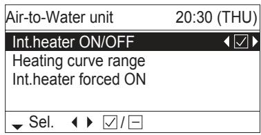
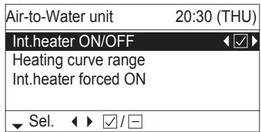
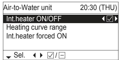
■ Int. heater ON/OFF
The internal heater of Air-to-Water unit can be disabled. When the internal heater is disabled, ☐ OFF icon appears.
Press ◀ ▶ button to switch ON/OFF.
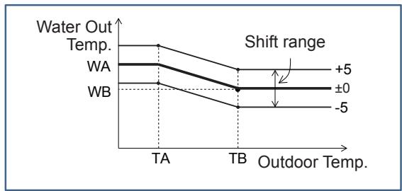
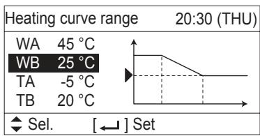
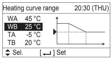
■ Heating curve range
It is able to select Heating curve range to automatically adjust the water out temperature with the outdoor temperature.
line
| Outdoor Temp. | Water Out Temp. | | ------------- | --------------- | | TA | +5 | | TB | ±0 | | WB | -5 |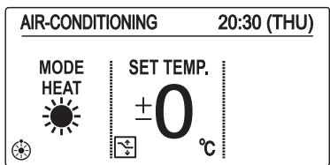
line
Heating curve range 20:30 (THU) | Label | Value | |---|---| | WA | 45 °C | | WB | 25 °C | | TA | -5 °C | | TB | 20 °C | Select. [←] Set![Heating curve range 20:30 (THU) WB: Water out temp. (Lo) 25 °C ^ Change [ ← ] Confirm](/content/2019/08/105595/images/045051190395bdc1cf8ab5bc11d0d0d4893ef5f647978fd5fd1e693ec5a67024.jpg)
The initial setting is “±0” as the set temperature. Water out temperature can be changed (shift) from ‘-5’ to ‘+5’ as the set temperature.
The Shape of Heating curve range is able to change at menu screen.
Select the temperature to change by ▲ ▼ button.
Press ← button, it is able to change the selected temperature.
Temperature range
| WA | 25~45°C |
| WB | 25~45°C |
| TA | -20~15°C |
| TB | 15~25°C |
The centralized controller displays the target water out temperature. It is only displayed information. It is not able to change the target water out temperature by the centralized controller.
■ Int. heater forced ON
The internal heater of Air-to-Water unit can be turned ON manually. When the internal heater is turned ON manually, 📄 icon appears.
* This feature is for emergency operation when the outdoor unit has trouble. Contact to service technician definitely before setting this function.
* Password will be required before setting this function.
Press ▲, ▼ button and select "Set" for forced ON.
Press ← button after checking the confirmation screen.
![Air-to-Water unit 20:30 (THU) Int.heater forced ON Set ◆ Change [ ← ] Confirm](/content/2019/08/105595/images/0f5384faf15296ab20ac33d54ef17ddfc8d03dab674718ec6780bc34cf8742a5.jpg)

Maintenance
Do not attempt to clean inside the unit by yourself.
WARNING
- For safety, be sure to turn the Air-to-Water off and disconnect the power before cleaning. (Otherwise, electric shock or injury may result because the fan is rotating at high speed.)
- Do not pour water on the indoor unit excluding water circuit. (This may damage the internal components and cause an electric shock hazard.)
CAUTION
● Never use solvents or harsh chemicals. Also, do not wipe plastic parts using very hot water.
(This may cause deformation or change in colour.)
- Some metal edges and fins are sharp. Be careful when you clean those parts.
(Injury may result.)
- Use a firm stool or ladder when cleaning an indoor unit installed in high locations.
Before Requesting Services
| Symptom | Cause | Action |
| The Air-to-Water unit does not operate although the power is turned on. | Power failure or after power failure | Press the power ON/OFF button on the remote controller. |
| The operation (power) button is turned off. | ·If the breaker is turned off, turn the power on.·If the breaker has been tripped, consult your dealer without turning it on. | |
| Fuse blow out. | Contact your dealer. | |
| Poor cooling or heating performance | Water circuit of indoor unit is clogged with dust or obstacles. | Remove dust or obstruction. |
| Water temperature is very cold (heating). | Preheat the water over 25°C. (operate only Air-to-Water unit) | |
| The air intake or air outlet of outdoor units is clogged with dust. | Remove the dust. | |
| Improper temperature settings | See “Tips for Energy Saving”. (P.4) | |
| The room is exposed to direct sunlight in cooling mode. | ||
| Doors or windows are open. | ||
| Too many heat sources in cooling mode. | Use minimum heat sources and in a short time. | |
| Too many people in the room in cooling mode. | Lower the temperature setting. |
If your Air-to-Water unit does not work properly even after checking each item of “Before Requesting Services” and “Troubleshooting”
- Stop the operation immediately and turn the power off. Then contact your dealer and report the serial number and symptom. You also report if the inspection mark △ and the letters E, F, H, L, P in combination with numbers appear on the LCD of the remote controller.
● Never repair the Air-to-Water unit by yourself since it is very dangerous for you to do so.
Troubleshooting
Check before consulting or requesting services.
| Symptom | Cause / Action | ||
| Indoor unit | Noise | Sound like streaming water is heard during operation or after operation. | Sound of water flowing inside unitSound of refrigerant liquid flowing inside unitSound of drainage water through drain pipe |
| Cracking noise is heard during operation or when operation stops. | Sound due to temperature changes of parts | ||
| Dewdrops accumulate near bottom during cooling operation. | Cold water accumulates dewdrop on the water piping. | ||
| Outdoor unit | No operation (When the power is turned on immediately / When operation is stopped and resumed immediately) | Operation is not activated for the first approx. 3 minutes because the compressor protection circuit is activated. | |
| Noise occurs during heating operation. | Defrost operation is in process. | ||
| Steam comes out during heating operation. | This is for smooth operation. | ||
| The fan continues to rotate even after the operation is stopped using the remote controller. | |||
| Outdoor unit | No operation(When the power is turned on immediately /When operation is stopped and resumedimmediately) | Operation is not activated for the first approx. 3 minutesbecause the compressor protection circuit is activated. |
| Noise occurs during heating operation. | Defrost operation is in process. | |
| Steam comes out during heating operation. | ||
| The fan continues to rotate even after theoperation is stopped using the remotecontroller. | This is for smooth operation. |
Error code
| Code | How to Release | |
| E03 | Remote controller communication error | Automatic |
| E04 | Abnormal indoor/outdoor communication error | Automatic |
| F01 | Abnormal refrigerant sensor 1 (E1) | Automatic |
| F02 | Abnormal water outlet sensor 1 (E2) | Automatic |
| F03 | Abnormal refrigerant sensor 2 (E3) | Automatic |
| F10 | Abnormal water intlet sensor (TA) | Automatic |
| F11 | Abnormal water outlet sensor 2 (BL) | Automatic |
| L13 | Mismatched indoor unit | Reset (On and off of the power supply) |
| L16 | Test run for water circuit is not finished | Do test run for water circuit |
| L25 | Unmatched remote controller | Reset (On and off of the power supply) |
| P07 | Abnormal Internal heater overload | Cancel from the remote controller |
| P09 | Abnormal water flow | Re-run |
| P12 | Abnormal water pump speed | Re-run |

Non usare guanti
Non usare penne
Nome delle parti
Modo SERBATOIO
flowchart
graph TD
    A["ALIM.ACQUA CALDA"] --> B["SERBAT."]
    B --> C["Temp. IMP. 65 °C"]
    C --> D["Temperatura impostata (acqua)"]
    D --> E["20:30 (GIO)"]
    E --> F["Icona"]
    F --> G["Descrizione"]
    G --> H["È possibile impostare la temperatura di uscita dell'acqua."]
    style A fill:#f9f,stroke:#333
    style E fill:#ccf,stroke:#333
Druk op het midden

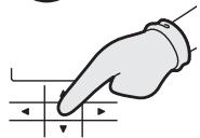
Geen handschoenen

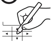
Geen pen
Menuscherm
![Schermnaam Huidige tijd en dag Menu 20:30 (THU) 1. Basic instructions 2. FLAP 3. Lock indiv. flap 4. ON/OFF timer ▼ Sel. ▶ Page [ ← ] Confirm](/content/2019/08/105595/images/9c77a91240f367716efa972910e115cb93d2bc3bf3d1ab9d2fa5ebc721d543b5.jpg)
![Menu 20:30 (THU) 8. Quiet operation 9. Power consumption monitor 10. Energy saving 11. Initial settings ◀ Sel. ◀ ▶ Page [←] Confirm](/content/2019/08/105595/images/f860d37c1b9d625ecf7bf133b343ea1638bb7380a261b45fab2163435b38023c.jpg)
![Initial settings 20:30 (THU) 1. Clock 2. Clock type 3. Controller name 4. Operation lock ▼ Sel. ▶ Page [←] Confirm](/content/2019/08/105595/images/174dca1502d29cfa011595475ee5a1cf1ad5644914ca1ad00b829531f95005e0.jpg)
-
FLAP
-
Lock indiv. flap
-
Filter info
-
Outing function
-
Energy saving
-
Initial settings
flowchart
graph TD
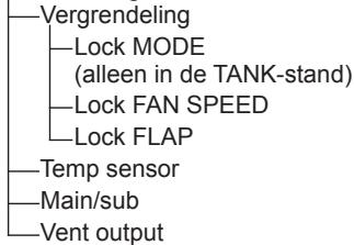
A["Vergrendeling"] --> B["Lock MODE (alleen in de TANK-stand)"]
B --> C["Lock FAN SPEED"]
B --> D["Lock FLAP"]
E["Temp sensor"] --> F["Main/sub"]
G["Vent output"] --> H["End"]
- Ventilation
![Me 8 9 10 11 This function is disabled. [→] Close Oct. Page [←] Confirm](/content/2019/08/105595/images/17f2d2fdcadb3f6cfdfc565fb4c0ecfea28212fe4867b67ea0ff5ff35347ea68.jpg)
Klok
Vergrendeling
TANK-stand
De Verwarmingscurve is in werking
■ Om de instelling te veranderen
■ Om te stoppen
Heat (Verwarmen)(Met Heating Curve
(Verwarmingscurve) : -5^ t/m + 5^ (offset)
Heat (Verwarmen)(Zonder Heating Curve
(Verwarmingscurve) : 25°C t/m 45°C

• Air-Conditioningstand
Onderhoud
![Me 8 9 10 11 This function is disabled. [→] Close Oct. Page [←] Confirm](/content/2019/08/105595/images/87eb0427e63215cbe43dc0d4035df63cf623ab896ab93c0726477d64214f54fb.jpg)
Relógio
4 Defina a data e a hora.
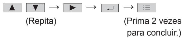
flowchart
graph LR
    A["▲"] --> B["▼"]
    B --> C["→"]
    C --> D["▶"]
    D --> E["→"]
    E --> F["←"]
    F --> G["→"]
    G --> H["≡"]
    I["(Repita)"] --> J["(Prima 2 vezes para concluir.)"]
Tipo de relógio
Modo de DEPÓSITO


NOTA
Modo de DEPÓSITO
line
Heating curve range 20:30 (THU) | Label | Value | |---|---| | WA | 45 °C | | WB | 25 °C | | TA | -5 °C | | TB | 20 °C | The chart displays a stepwise decreasing trend in the 'Temperature' value from left to right. The 'Sel.' (Selected) annotation is [←] Set below the chart.![Heating curve range 20:30 (THU) WB: Water out temp. (Lo) 25 °C ^ Change [ ← ] Confirm](/content/2019/08/105595/images/930eb932205d5b91d2ab0fc7710efd9f4863f144e885c26ffa0c6163980aa231.jpg)
Manutenção
![Initial settings 20:30 (THU) 1. Clock 2. Clock type 3. Controller name 4. Operation lock ▼ Sel. ▶ Page [ ← ] Confirm](/content/2019/08/105595/images/94a4965ba650f48d20d46f989402d58382c8959eab4e955deec78f16324a245c.jpg)
-
FLAP
-
Lock indiv. flap
-
Filter info
-
Outing function
-
Energy saving
-
Initial settings

flowchart
graph TD
    A["Operation lock"] --> B["Lock MODE"]
    B --> C["(μόνο λειτουργία ΔΕΞΑΜΕΝΗΣ)"]
    B --> D["Lock FAN SPEED"]
    B --> E["Lock FLAP"]
    F["Temp sensor"] --> G["Main/sub"]
    F --> H["Vent output"]
- Ventilation
![Mg 20.00 (T) U 8 9 This function is disabled. 10 [→] Close 11 ↓ Oct. ↗ Page [←] Confirm](/content/2019/08/105595/images/04e1bff2f943af830946335f5ae52e3a62b89ae1d5aa8e631eb30f8eae81db11.jpg)
Polói


ΣΗΜΕΙΩΣΗ
line
Heating curve range 20:30 (THU) | Label | Value | |---|---| | WA | 45 °C | | WB | 25 °C | | TA | -5 °C | | TB | 20 °C | Select. [←] Set![Heating curve range 20:30 (THU) WB: Water out temp. (Lo) 25 °C ^ Change [←] Confirm](/content/2019/08/105595/images/ed98799ba81f62f02daa2d7d74bbc9418ecc292461feb79f849ad6af24a2b5fa.jpg)
![Menu 20:30 (THU) 8. Quiet operation 9. Power consumption monitor 10. Energy saving 11. Initial settings ◆ Sel. ◀ ▶ Page [←] Confirm](/content/2019/08/105595/images/1769539f43d25a01132d627213e83ebc8221b0c5077c7ae46b2a1ad92a24d0dd.jpg)
![Initial settings 20:30 (THU) 1. Clock 2. Clock type 3. Controller name 4. Operation lock ▼ Sel. ▶ Page [←] Confirm](/content/2019/08/105595/images/dc5edc0da0364300247e7320d674eb6cb45375d8156c1c713f11686454a8ab07.jpg)
- FLAP
- Lock indiv. flap
- Filter info
-
Outing function
-
Energy saving
- Initial settings
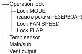
flowchart
graph TD
    A["Operation lock"] --> B["Lock MODE (само в режим PE3EPBOAP)"]
    B --> C["Lock FAN SPEED"]
    C --> D["Lock FLAP"]
    E["Temp sensor"] --> F["Main/sub"]
    G["Vent output"] --> H["End"]
- Ventilation
![This function is disabled. [→] Close](/content/2019/08/105595/images/dcadc3b1a95f11bd85f6943237a40feadaa22770932395fe33b41e796e3a60e5.jpg)
Часовник
Режим РЕЗЕРВОАР
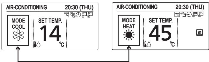
flowchart
graph TD
    A["Cool"] --> B["Heat"]
    B --> A

| Menu | 20:30 (THU) |
| 11. Initial settings | |
| 12. Ventilation | |
| 13. Setting list | |
| 14. Air-to-Water unit | |
| ▲ Sel. ◀ Page [←] Confirm | |
- Режим Климатизация
3 Изберете елемент за настройка.
Режим РЕЗЕРВОАР
Режим Климатизация
![Heating curve range 20:30 (THU) WA 45 °C WB 25 °C TA -5 °C TB 20 °C ◆ Sel. [←] Set](/content/2019/08/105595/images/045966cbca9eeb0c0bb0d4dc909ba9bba76e85094c4c6196ebf54b9aabc99edd.jpg)
| Heating curve range 20:30 (THU) |
| WB: Water out temp. (Lo) |
| 25 °C |
| ^ Change [←] Confirm |

Eldivensiz

Kalemsiz
TÜRKÇE
Parçaların Adları
TANK modu
flowchart
graph TD
    A["HOT-WATER-SUPPLY"] --> B["TANK"]
    B --> C["SET TEMP. 65 °C"]
    C --> D["Ayar sıcaklığı (su)"]
    D --> E["Sıme"]
    E --> F["Tanımı"]
    F --> G["Su Çıkış Sıcaklığı ayarlanabilir."]
    H["20:30 (THU)"] --> I["Control buttons with icons"]
    I --> A
    style A fill:#f9f,stroke:#333
    style B fill:#ccf,stroke:#333
    style C fill:#cfc,stroke:#333
    style D fill:#fcc,stroke:#333
    style E fill:#cff,stroke:#333
    style F fill:#ffc,stroke:#333
    style G fill:#cfc,stroke:#333
![Menu 20:30 (THU) 8. Quiet operation 9. Power consumption monitor 10. Energy saving 11. Initial settings ◀ Sel. ◀ ▶ Page [←] Confirm](/content/2019/08/105595/images/153637054429831174152c4bafe2253c8385e75c007f5fd8a96565fdfe52017a.jpg)
![Initial settings 20:30 (THU) 1. Clock 2. Clock type 3. Controller name 4. Operation lock ▼ Sel. ▶ Page [←] Confirm](/content/2019/08/105595/images/49cef108139ebc3b5021a15e8ddb616368a76af51136ddb608f2d585fecc9506.jpg)
- FLAP
- Lock indiv. flap
-
Filter info
-
Outing function
-
Energy saving
-
Initial settings
flowchart
graph TD
    A["Operation lock"] --> B["Lock MODE (yalnızca TANK modunda)"]
    B --> C["Lock FAN SPEED"]
    C --> D["Lock FLAP"]
    E["Temp sensor"] --> F["Main/sub"]
    G["Vent output"]
- Ventilation
![Me 8 9 10 11 This function is disabled. [→] Close ← Page [←] Confirm](/content/2019/08/105595/images/e77bafc1e8f19ce42f0888ab35371047c61d4f9c5ed50f590c9d3432676b7aa9.jpg)
Saat
TANK modu
NOT
TANK modu
Klima modu
line
Heating curve range 20:30 (THU) | Label | Value | |---|---| | WA | 45 °C | | WB | 25 °C | | TA | -5 °C | | TB | 20 °C | Select [←] Set![Heating curve range 20:30 (THU) WB: Water out temp. (Lo) 25 °C ^ Change [ ← ] Confirm](/content/2019/08/105595/images/78790e6ed61c55c234f3d2dd6016dede9f2b1d571e956cdebb77b9e815a2f468.jpg)
Air-to-Water Heatpump (Type W1)
| Model Name | S-80MW1E5 | S-125MW1E5 | |
| Power Source | 220 / 230 / 240 V ~ 50Hz | ||
| Cooling capacity | kW | 8.0 | 12.5 |
| BTU/h | 27,300 | 42,700 | |
| Heating capacity | kW | 9.0 | 14.0 |
| BTU/h | 30,700 | 47,800 | |
| Sound Pressure level | dB(A) | 37 | 39 |
| Sound Power level | dB(A) | 50 | 52 |
| Unit Dimensions (H×W×D) | mm | 892×502×353 | 892×502×353 |
| Net weight | kg | 43 | 43 |
Corresponding language table
| English | Français | Español | Deutsch |
| Air-to-Water Heatpump (Type W1) | Pompe à chaleur hydraulique (Type W1) | Bomba de calor de unidad de aire-agua (tipo W1) | Luft-Wasser-Wärmepumpe (Typ W1) |
| 3WAY (Type MF2) | 3WAY (Type MF2) | 3WAY (tipo MF2) | 3WAY (Typ MF2) |
| English | Italiano | Nederlands | Português |
| Air-to-Water Heatpump (Type W1) | Pompa di calore aria-acqua (tipo W1) | Lucht-naar-Water Warmtepomp (type W1) | Bomba de Calor Ar-Água (Tipo W1) |
| 3WAY (Type MF2) | 3WAY (tipo MF2) | 3WAY (type MF2) | 3WAY (Tipo MF2) |
| English | Ελληνικη | Βългарски | Türkçe |
| Air-to-Water Heatpump(Type W1) | Θερμική αντλία κλιματιστικού(Túπος W1) | Термопомпа Въздух-вода(тип W1) | Havadan Suya Isı Pompası(W1 tipi) |
| 3WAY (Type MF2) | 3WAY (Túπος MF2) | 3WAY (тип MF2) | 3WAY (MF2 tipi) |
Corresponding language table
| English | Français | Español | Deutsch |
| Model Name | Nom du modèle | Nombre del modelo | Modellbezeichnung |
| Power Source | Source d'alimentation | Fuente de alimentación | Spannungsquelle |
| Cooling Capacity | Capacité de refroidissement | Capacidad de refrigeración | Kühlleistung |
| Heating Capacity | Capacité de chauffage | Capacidad de calefacción | Heizleistung |
| Sound Pressure Level | Niveau de pression sonore | Nivel de presión acústica | Schalldruckpegel |
| Sound Power Level | Niveau de puissance sonore | Nivel de potencia acústica | Schallleistungspegel |
| Unit Dimensions (HxWxD; mm) | Dimensions d'unité (HxLxP ; mm) | Dimensiones de la unidad (Alto x Largo x Ancho; mm) | Geräteabmessungen (H x B x T [mm]) |
| Net Weight (kg) | Poids net (kg) | Peso neto (kg) | Nettogewicht (kg) |