
EY-7950 - Cordless drill driver PANASONIC - Free user manual and instructions
Find the device manual for free EY-7950 PANASONIC in PDF.
| Brand | Panasonic |
| Model | EY-7950 |
| Product type | Cordless impact drill/driver |
| Motor voltage | 18 V DC |
| No-load speed (low) | 0 - 430 min⁻¹ |
| No-load speed (high) | 0 - 1650 min⁻¹ |
| Impact frequency (low) | 1800 - 7740 min⁻¹ |
| Impact frequency (high) | 6840 - 29700 min⁻¹ |
| Chuck capacity | 1.5 - 13 mm (keyless) |
| Tightening torque (clutch) | 18 positions, 1.0 - 6.9 N·m |
| Total length | 235 mm |
| Weight (with battery) | 2.3 kg |
| Battery type | Li-ion 18 V (model EY9L44) |
| Charger | EY0L81, charge time usable 50 min / full 65 min |
| Protection rating | IP56 (dust and water jet resistance) |
| Operating modes | Screwdriving, wood/metal drilling, concrete hammer drilling |
| Additional features | LED light, motor/battery overheat indicator, low battery indicator, motor brake, auxiliary handle |
| Included accessories | Li-ion 18 V battery, charger, auxiliary handle |
| Maintenance | Clean with a dry, clean cloth; do not use water or solvents |
| Safety | Switch lock, overload and overheat protection, use of auxiliary handle |
| Warranty | Limited warranty (see manual) |
Frequently Asked Questions - EY-7950 PANASONIC
User questions about EY-7950 PANASONIC
0 question about this device. Answer the ones you know or ask your own.
Ask a new question about this device
Download the instructions for your Cordless drill driver in PDF format for free! Find your manual EY-7950 - PANASONIC and take your electronic device back in hand. On this page are published all the documents necessary for the use of your device. EY-7950 by PANASONIC.
USER MANUAL EY-7950 PANASONIC
natural_image
Line drawing of a handheld electric drill press (no text or symbols)Before operating this unit, please read these instructions completely and save this manual for future use.

| (A) | Keyless drill chuckSchlüsselfreies BohrfutterMandrino porte-foret sans filMandrino autoserranteBoorkop zonder sleutelMandril sin llaveNøglefri borepatronNyckellös borrchuckNøkkelfri drillchuckAvaimeton poran kiinnityslaite | (B) | Clutch handleKupplungsringPoignée de l'embrayageImpugnatura frizioneKoppelingshandgreepMango de embragueKoblinghåndtagKopplingshandtagKoblingshåndtakKytkimen kahva |
| (C) | Speed selector switchBereichsschalterInterrupteur de sélection de vitesseRegolatore di velocitàSnelheidskeuzeschakelaarInterruptor selector de velocidadHastighedsvælgerHastighetsomkopplareHastighetskontrollNopeuden valintakytkin | (D) | Forward/Reverse leverRechts/Linkslauf SchalterLevier d'inversion marche avant-marche arrièreLeva di avanzamento/inversioneVoorwaarts/achterwaarts-hendelPalanca de avance/inversiónGreb til forlæns/baglæns retningRiktningsomkopplareForover/Revers bryterEteenpäin/taaksepäin vipu |
| (E) | Alignment marksAusrichtmarkierungenMarques d'alignementMarcature allineamentoUitlijntekensMarcas de alineaciónFlugtemærkerAnpassningsmärkenOpprettingsmerkeSovitusmerkit | (F) | Battery pack release buttonAkku-EntriegelungsknopfBouton de libération de batterie autonomeTasto di rilascio pacco batteriaAccu-ontgrendeltoetsBotón de liberación de bateríaUdløserknap til batteripakningFrigöringsknapp för batteriUtløserknapp for batteripakkeAkkupaketin irrotuspainike |
| (G) | Battery packAkkuBatterie autonomePacco batteriaAccuBateríaBatteripakningBatteriBatteripakkeAkku | (H) | Control panelBedienfeldPanneau de commandePannello di controlloBedieningspaneelPanel de controleKontrolpanelKontrollpanelKontrollpanelSäätöpaneeli |
| (I) | Overheat warning lampÜberhitzungs-WarnlampeTémoin d'avertissement de surchauffeSpia avvertenza surriscaldamentoOververhitting-waarschuwingslampjeLuz de advertencia de sobrecalentamientoAdvarselslamp til overophedningVarningslampa för överhettningVarsellampe for overopphetingYlikuumenemisen varoituslamppu | (J) | LED light on/off buttonLED-Leuchten-EIN/AUS-TasteBouton Marche/Arrêt de la lumière DELTasto di accensione e spegnimento della luce LEDAan/uit-toets (ON/OFF) voor LED-lampjeBotón ON/OFF de luz LEDTÄEND/SLUK-knap til LED-lysStrömbrytare för LED-ljusPÅ/AV-knapp for LED-lysLED-valon kytkin/katkaisupainike |
| (K)(M) | LED lightLED-LeuchteLumière DELLuce LEDLED-lampjeLuz indicadoraLED-lysLED-ljusLED-lysLED-valoVariable speed control triggerBetriebsschalterGâchette de commande de vitesseGrilletto di controllo velocità variableStartschakelaar variabele snelheidDisparador del control de velocided variableKontroludløser for variabel hastighedSteglös varvtalsreglerareHovedbryter, trinnløsNopeudensäätökytkin | (L)(N) | Battery low warning lampAkkuladungs-WarnlampeTémoin d'avertissement de batterie basseSpia avvertenza batteria scaricaWaarschuwingslampje voor lage accuspanningLuz de aviso de baja carga de bateríaAdvarselslampes batterieffekt lavVarningslampa för svagt batteriVarsellampe for at batteriet er for lavtAlhaisen akkujännitteen varoituslamppuSupport handleZusatzgriffManche de supportManiglia di sostegnoSteungreepMango de soporteHjælpehåndtagStödhandtagStøttehåndtakTukikahva |
| (O) | Battery chargerLadegerätChargeur de batterieCaricabatterieAcculaderCargador de bateríaBatteriopladerBatteriladdareBatteriladerAkkulaturi | (P) | Battery pack coverAkkuabdeckungCouvercle de la batterie autonomeCoperchio pacco batteriaAccudekselCubierta de bateríaAkkuafdækningBatterilockBatteripakkedekselAkun kansi |
Original instructions: English Translation of the original instructions: Other languages
This tool, as a complete unit with a battery pack, satisfies appropriate IP Degrees of Protection based on the IEC regulations.
Definition of IP code
IP5X: Ingress of dust is not totally prevented, but dust shall not penetrate in a quantity to interfere with satisfactory operation of the tool or to impair safety (In case that the talcum powder under 75 m intrudes inside the tool) IPX6: Water projected in powerful jets against the tool from any direction shall have no harmful effects (In case that, with a nozzle of 12.5 mm inner diameter, approximately 100 L/min of normal temperature water is injected to the tool for 3 minutes from 3 meter distance)
LIMITED WARRANTY
The rating of IP56 qualifies this tool for the minimum impact of water or dust, but not for the assurance of performance in such conditions. See Safety and Operating Instructions for further details for proper operation.
Read “the Safety Instructions” booklet and the following before using.
I. INTENDED USE
These tools can be used to tighten screws in clutch mode and to drill holes in wood and metal in drill mode. Additionally, model EY7950 can be used to drill holes in soft concrete and similar materials in hammer mode.
Read the Safety Instructions booklet and the following before using.
II. ADDITIONAL SAFETY RULES
1) Wear ear protectors.
Exposure to noise can cause hearing loss.
2) Use auxiliary handle supplied with the tool.
Loss of control can cause personal injury.
3) Hold power tools by insulated gripping surfaces when performing an operation where the cutting tool may contact hidden wiring; contact with a "live" wire will make exposed metal parts of the tool "live" and shock the operator.
4) Wear a dust mask, if the work causes dust.
5) Be aware that this tool is always in an operating condition, since it does not have to be plugged into an electrical outlet.
6) When drilling or driving into walls, floors, etc., "live" electrical wires may be encountered. DO NOT TOUCH THE CHUCK OR ANY FRONT METAL PARTS OF THE TOOL! Hold the tool only by the plastic handle to prevent electric shock in case you drill or drive into a "live" wire.
7) If the bit becomes jammed, immediately turn the trigger switch off to prevent an overload, which can damage the battery pack or motor.
Use reverse motion to loosen jammed bits.
8) Do NOT operate the Forward/Reverse lever when the trigger switch is on. The battery will discharge rapidly and damage to the unit may occur.
9) During charging, the charger may become slightly warm. This is normal. Do NOT charge the battery for a long period.
10) When storing or carrying the tool, set the Forward/Reverse lever to the center position (switch lock).
11) Do not strain the tool by holding the speed control trigger halfway (speed control mode) so that the motor stops.
12) Do not operate the speed selector switch (LOW-HIGH) while pulling on the speed control trigger. This can cause the rechargeable battery to wear quickly or damage the internal mechanism of the motor.
| Symbol | Meaning |
| V | Volts |
| --- | Direct current |
| n_o | No load speed |
| ...min ^-1 | Revolutions or reciprocations per minutes |
| Ah | Electrical capacity of battery pack |
| ∪ | Forward rotation |
| ∪ | Reverse rotation |
| ↑ | Rotation with hammering |
| Rotation only | |
| To reduce the risk of injury, user must read and understand instruction manual. | |
| For indoor use only. |
WARNING:
- Do not use other than the Panasonic battery packs that are designed for use with this rechargeable tool.
- Panasonic is not responsible for any damage or accident caused by the use of the recycled battery pack and the counterfeit battery pack.
- Do not dispose of the battery pack in a fire, or expose it to excessive heat.
- Do not drive the likes of nails into the battery pack, subject it to shocks, dismantle it, or attempt to modify it.
- Do not allow metal objects to touch the battery pack terminals.
- Do not carry or store the battery pack in the same container as nails or similar metal objects.
- Do not charge the battery pack in a high-temperature location, such as next to a fire or in direct sunlight. Otherwise, the battery may overheat, catch fire, or explode.
- Never use other than the dedicated charger to charge the battery pack. Otherwise, the battery may leak, overheat, or explode.
• After removing the battery pack from the tool or the charger, always reattach the pack cover. Otherwise, the battery contacts could be shorted, leading to a risk of fire. - When the Battery Pack Has Deteriorated, Replace It with a New One.
Continued use of a damaged battery pack may result in heat generation, ignition or battery rupture.
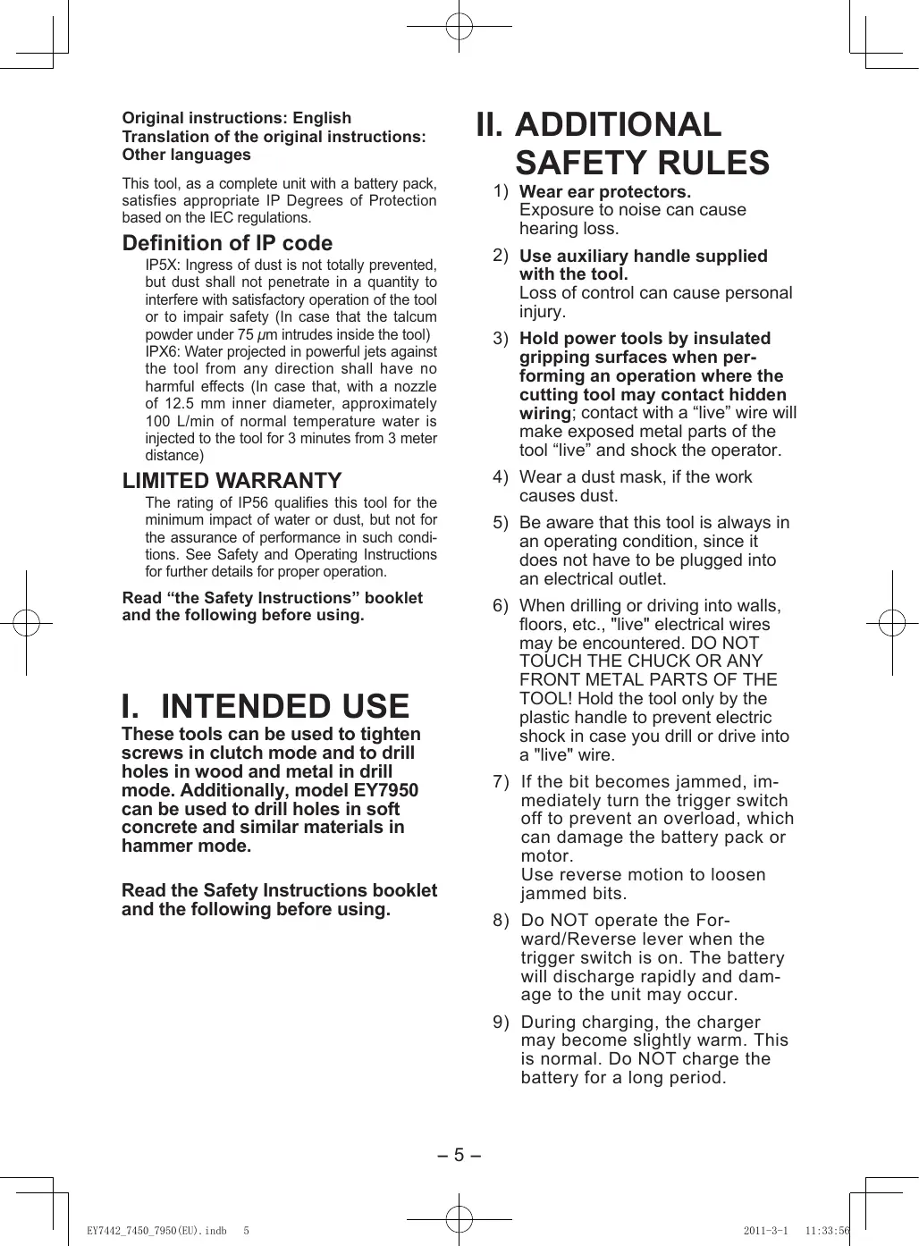
III.ASEMBLY Attaching or Removing Bit
NOTE:
When attaching or removing a bit, disconnect battery pack from tool or place the switch in the center position (switch lock).
This tool is equipped with a keyless drill chuck.
1. Attachment
Insert the bit and turn the lock collar clockwise (looking from the front) to tighten firmly until it stops clicking.
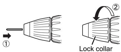
2. Removal
Turn the lock collar counterclockwise (looking from the front), then remove the bit.
NOTE:
If excessive play occurs in the chuck, secure the drill in place and ① open the chuck jaws by turning the lock collar and ② tighten the screw (left-handed screw) with a screw-driver by turning it counterclockwise (viewed from the front).

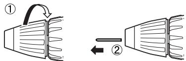
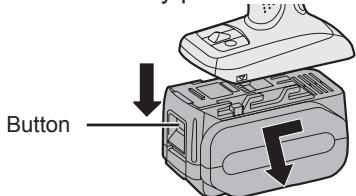
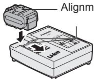
Attaching or Removing Battery Pack
1. To connect the battery pack:
Line up the alignment marks and attach the battery pack.
- Slide the battery pack until it locks into position.
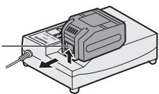
2. To remove the battery pack:
Pull the button from the front to release the battery pack.
Support handle
Place the support handle at your favorite position and tighten the handle securely.

Always use the support handle to ensure operating safety.
- The speed increases with the amount of depression of the trigger. When beginning work, depress the trigger slightly to start the rotation slowly.
- A feedback electronic controller is used to give a strong torque even in low speed.
- The brake operates when the trigger is released and the motor stops immediately.
NOTE:
- When the brake operates, a braking sound may be heard. This is normal.
- Sparks from the motor brush may be visible through the body vent holes on the back of the tool during switching and braking due to the load imposed on the motor. This does not indicate a problem with the tool.
Switch and Forward/Reverse Lever Operation

CAUTION:
To prevent damage, do not operate Forward/Reverse lever until the bit comes to a complete stop.
Forward Rotation Switch Operation
- Push the lever for forward rotation.
- Depress the trigger switch slightly to start the tool slowly.
- The speed increases with the amount of depression of the trigger for efficient tightening of screws and drilling. The brake operates and the chuck stops immediately when the trigger is released.
- After use, set the lever to its center position (switch lock).
Reverse Rotation Switch Operation
- Push the lever for reverse rotation. Check the direction of rotation before use.
- Depress the trigger switch slightly to start the tool slowly.
- After use, set the lever to its center position (switch lock).
Clutch Torque Setting
Adjust the torque to one of the 18 clutch settings or "2" position (EY7442, EY7450).
Adjust the torque to one of the 18 clutch settings or "Z", "↑" position (EY7950).
NOTE:
Always make sure to stop operation of the tool and disengage it from the work, when you select Hammering mode from Drilling mode or when you shift to Drilling mode from Hammering mode by rotating clutch handle.
CAUTION:
Set the clutch setting at this mark (◀) before actual operation.

If the clutch handle cannot be set at "drilling" or "hammering" mode after drilling with clutch function, set the clutch handle at position 1 and operate the clutch for a second.
Speed Selection
Choose a low or high speed to suit the use. HIGH

The more the variable speed control trigger is pulled, the higher the speed becomes.
WARNING:
- Do not inhale any smoke emitted from the tool or battery pack as it may be harmful.
CAUTION:
- Check the speed selector switch before use.
- Use at low speed when high torque is needed during operation. (Using at high speed when high torque is required may cause a motor breakdown.)
- Do not use the tool in a manner that causes the motor to lock up. Doing so may damage the tool and battery pack, resulting in smoke or fire.
- Do not operate the speed selector switch (LOW-HIGH) while pulling on the speed control trigger. This can cause the rechargeable battery to wear quickly or damage the internal mechanism of the motor.
* See specifications for "MAXIMUM RECOMMENDED CAPACITIES".
CAUTION:
- To prevent excessive temperature increase of the tool surface, do not operate the tool continuously using two or more battery packs. The tool needs cool-off time before switching to another pack.
- Do not close up vent holes on the sides of the body during operation. Otherwise, the machine function is adversely affected to cause a failure.
- Do NOT strain the tool (motor). This may cause damage to the unit.
- Use the tool in such a way as to prevent the air from the body vent holes from blowing directly onto your skin. Otherwise, you may get burned.
Bit-locking Function
- With the trigger switch not engaged and a screwdriver bit locked in place, the tool can be used as a manual screwdriver.
(EY7442: up to 36 N·m, 367kgf-cm, 319 in-lbs) (EY7450, 7950: up to 40 N·m, 408kgf-cm, 353 in-lbs)
There will be a little play in the chuck, but this is not a malfunction.
- This feature is handy for tightening screws that require more torque than the maximum torque of the driver (position 1 on the clutch), for confirming the tightness of a screw or to loosen an extremely tight screw.
natural_image
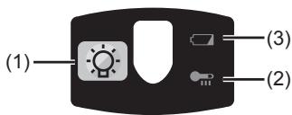
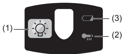
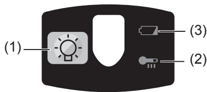
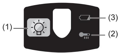
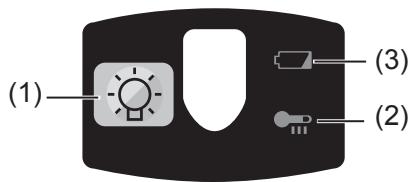
Illustration of a hand using a power drill press to lift a battery (no text or symbols present)Control Panel

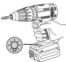
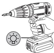
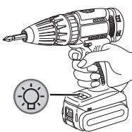
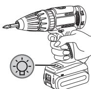
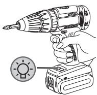
(1) LED light

natural_image
Illustration of a hand holding a drill bit with a power supply device nearby (no text or symbols)Before the use of LED light, always pull the power switch once.
Press 🙏 the LED light button.
The light illuminates with very low current, and it does not adversely affect the performance of the tool during use or its battery capacity.
CAUTION:
- The built-in LED light is designed to illuminate the small work area temporarily.
- Do not use it as a substitute for a regular flashlight, since it does not have enough brightness.
- LED light turns off when the tool has not been used for 5 minutes.
Caution: DO NOT STARE INTO BEAM.
Use of controls or adjustments or performance of procedures other than those specified herein may result in hazardous radiation exposure.
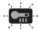
(2) Overheat warning lamp

Off (normal operation)


Flashing: Overheat (battery)
Indicates operation has been halted due to motor or battery overheating.
To protect the motor or battery, be sure to note the following when carrying out this operation.
- If the motor or battery becomes hot, the protection function will be activated and the motor or battery will stop operating. The overheat warning lamp on the control panel illuminates or flashes when this feature is active.
- If the overheating protection feature activates, allow the tool to cool thoroughly (at least 30 minutes). The tool is ready for use when the overheat warning lamp goes out.
- Avoid using the tool in a way that causes the overheating protection feature to activate repeatedly.
- If the tool is operated continuously under high-load conditions or if it is used in hot-temperature conditions (such as during summer), the overheating protection feature may activate frequently.
- If the tool is used in cold-temperature conditions (such as during winter) or if it is frequently stopped during use, the overheating protection feature may not activate.
- The performance of the EY9L42 deteriorates significantly at and below 10^ due to work conditions and other factors.
(3) Battery low warning lamp

Off (normal operation)

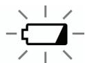
Flashing (No charge) Battery protection feature active
Excessive (complete) discharging of lithium ion batteries shortens their service life dramatically. The driver includes a battery protection feature designed to prevent excessive discharging of the battery pack.
- The battery protection feature activates immediately before the battery loses its charge, causing the battery low warning lamp to flash.
- If you notice the battery low warning lamp flashing, charge the battery pack immediately.
[Battery Pack]
For Appropriate Use of Battery pack
Li-ion Battery pack
- For optimum battery life, store the Li-ion battery pack following use without charging it.
- When charging the battery pack, confirm that the terminals on the battery charger are free of foreign substances such as dust and water etc. Clean the terminals before charging the battery pack if any foreign substances are found on the terminals.
The life of the battery pack terminals may be affected by foreign substances such as dust and water etc. during operation. - When battery pack is not in use, keep it away from other metal objects like: paper clips, coins, keys, nails, screws, or other small metal objects that can make a connection from one terminal to another. Shorting the battery terminals together may cause sparks, burns or a fire.
- When operating the battery pack, make sure the work place is well ventilated.
- When the battery pack is removed from the main body of the tool, replace the battery pack cover immediately in order to prevent dust or dirt from contaminating the battery terminals and causing a short circuit.
Battery Pack Life
The rechargeable batteries have a limited life. If the operation time becomes extremely short after re-charging, replace the battery pack with a new one.
Battery Recycling
ATTENTION:
For environmental protection and recycling of materials, be sure that it is disposed of at an officially assigned location, if there is one in your country.
[Battery Charger]
Charging
Cautions
- If the temperature of the battery pack falls approximately below -10^ (14°F), charging will automatically stop to prevent degradation of the battery.
- The ambient temperature range is between 0^ (32°F) and 40^ (104°F). If the battery pack is used when the battery temperature is below 0^ (32°F), the tool may fail to function properly.
- When charging a cool battery pack (below 0^ ( 32^ )) in a warm place, leave the battery pack at the place and wait for more than one hour to warm up the battery to the level of the ambient temperature.
- Cool down the charger when charging more than two battery packs consecutively.
- Do not insert your fingers into contact hole, when holding charger or any other occasions.
To prevent the risk of fire or damage to the battery charger.
- Do not use power source from an engine generator.
- Do not cover vent holes on the charger and the battery pack.
- Unplug the charger when not in use.
Li-ion Battery Pack
NOTE:
Your battery pack is not fully charged at the time of purchase. Be sure to charge the battery before use.
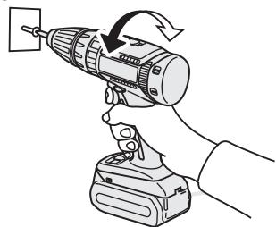
Battery charger
- Plug the charger into the AC outlet.
-
Insert the battery pack firmly into the charger.
-
Line up the alignment marks and place the battery onto the dock on the charger.
- Slide forward in the direction of the arrow.
- During charging, the charging lamp will be lit.
When charging is completed, an internal electronic switch will automatically be triggered to prevent overcharging.
- Charging will not start if the battery pack is warm (for example, immediately after heavy-duty operation). The orange standby lamp will be flashing until the battery cools down. Charging will then begin automatically.
- The charge lamp (green) will flash slowly once the battery is approximately 80% charged.
- When charging is completed, the charging lamp in green color will turn off.
- If the temperature of the battery pack is 0^ C or less, charging takes longer to fully charge the battery pack than the standard charging time. Even when the battery is fully charged, it will have approximately 50% of the power of a fully charged battery at normal operating temperature.
- Consult an authorized dealer if the charging lamp (green) does not turn off.
- If a fully charged battery pack is inserted into the charger again, the charging lamp lights up. After several minutes, the charging lamp in green color will turn off.
- Remove the battery pack while the battery pack release button is held up.
Battery pack release button
natural_image
Illustration of a device with a sensor and control panel, no visible text or symbolsLAMP INDICATIONS
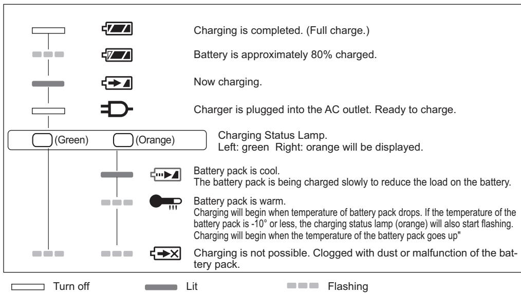
flowchart
graph TD
    A["Charging is completed. (Full charge.)"] --> B["Battery is approximately 80% charged."]
    B --> C["Now charging."]
    C --> D["Charger is plugged into the AC outlet. Ready to charge."]
    D --> E["(Green) (Orange)"]
    E --> F["Charging Status Lamp. Left: green Right: orange will be displayed."]
    F --> G["Battery pack is cool. The battery pack is being charged slowly to reduce the load on the battery."]
    G --> H["Battery pack is warm. Charging will begin when temperature of battery pack drops. If the temperature of the battery pack is -10° or less, the charging status lamp (orange) will also start flashing. Charging will begin when the temperature of the battery pack goes up""]
    H --> I["Charging is not possible. Clogged with dust or malfunction of the battery pack."]
Information for Users on Collection and Disposal of Old Equipment and used Batteries

These symbols on the products, packaging, and/or accompanying documents mean that used electrical and electronic products and batteries should not be mixed with general household waste.
For proper treatment, recovery and recycling of old products and used batteries, please take them to applicable collection points, in accordance with your national legislation and the Directives 2002/96/EC and 2006/66/EC.
By disposing of these products and batteries correctly, you will help to save valuable resources and prevent any potential negative effects on human health and the environment which could otherwise arise from inappropriate waste handling.
For more information about collection and recycling of old products and batteries, please contact your local municipality, your waste disposal service or the point of sale where you purchased the items.
Penalties may be applicable for incorrect disposal of this waste, in accordance with national legislation.
For business users in the European Union
If you wish to discard electrical and electronic equipment, please contact your dealer or supplier for further information.
[Information on Disposal in other Countries outside the European Union]
These symbols are only valid in the European Union. If you wish to discard these items, please contact your local authorities or dealer and ask for the correct method of disposal.
Note for the battery symbol (bottom two symbol examples):
This symbol might be used in combination with a chemical symbol. In this case it complies with the requirement set by the Directive for the chemical involved.
V. MAINTENANCE
- Use only a dry, soft cloth for wiping the unit. Do not use a damp cloth, thinner, benzine, or other volatile solvents for cleaning.
- In the event that the inside of the tool or battery pack is exposed to water, drain and allow to dry as soon as possible. Carefully remove any dust or iron filings that collect inside the tool. If you experience any problems operating the tool, consult with a repair shop.
VI. ACCESSORIES
Use only bits suitable for size of drill's chuck.
VII. APPENDIX MAXIMUM RECOMMENDED CAPACITIES
| Model | EY7442 | EY7450 | EY7950 | |
| Screw driving | Machine screw | M8 | ||
| Wood screw | 10 mm or 6.8 mm | |||
| Drilling | Self-drilling screw | 6 mm | ||
| For Wood | 36 mm | |||
| For Metal | 13 mm | |||
| For Masonry | 13 mm | |||
VIII. SPECIFICATIONS
MAIN UNIT
| Model | EY7442 | EY7450 | EY7950 | |
| Motor voltage | 14.4 V | 18 V | ||
| No load speed | Low | 0 - 410 min^-1 | 0 - 430 min^-1 | |
| High | 0 - 1530 min^-1 | 0 - 1650 min^-1 | ||
| Blows Rate Per Minute | Low | — | 1800 - 7740 min^-1 | |
| High | — | 6840 - 29700 min^-1 | ||
| Chuck capacity | 1.5 mm - 13 mm (1/16 - 1/2) | |||
| Clutch torque | Approx 1.0 N · m - 6.9 N · m | |||
| Overall length | 218 mm (8-9/16") | 218 mm (8-9/16") | 235 mm (9-1/4") | |
| Weight (with battery pack) | 2.05 kg (4.5 lbs) | 2.15 kg (4.7 lbs) | 2.3 kg (5.0 lbs) | |
BATTERY PACK
| Model | EY9L41 | EY9L42 | EY9L44 | EY9L50 |
| Storage battery | Li-ion | |||
| Battery voltage | 14.4V DC(3.6V X 4 cells) | 14.4V DC(3.6V X 8 cells) | 18V DC(3.6V X 10 cells) | |
BATTERY CHARGER
| Model | EY0L81 | |||
| Electrical rating | See the rating plate on the bottom of the charger. | |||
| Charging time | EY9L41 | EY9L42 | EY9L44 | EY9L50 |
| Usable:45minFull:60 min | Usable:30minFull:35 min | Usable:50 minFull:65 min | ||
NOTE: This chart may include models that are not available in your area. Please refer to the latest general catalogue.
NOTE: For the dealer name and address, please see the included warranty card.
ONLY FOR U. K.
IX. ELECTRICAL PLUG INFOR- MATION
FOR YOUR SAFETY PLEASE READ THE FOLLOWING TEXT CAREFULLY
This appliance is supplied with a moulded three pin mains plug for your safety and convenience.
A 5 amp fuse is fitted in this plug.
Should the fuse need to be replaced please ensure that the replacement fuse has a rating of 5 amp and that it is approved by ASTA or BSI to BS1362.
Check for the ASTA mark 🎨 or the BSI mark 🌿 on the body of the fuse.
If the plug contains a removable fuse cover you must ensure that it is refitted when the fuse is replaced.
If you lose the fuse cover the plug must not be used until a replacement cover is obtained.
A replacement fuse cover can be purchased from your local Panasonic Dealer.
IF THE FITTED MOULDED PLUG IS UN- SUITABLE FOR THE SOCKET OUTLET IN YOUR HOME THEN THE FUSE SHOULD BE REMOVED AND THE PLUG CUT OFF AND DISPOSED OF SAFELY.
THERE IS A DANGER OF SEVERE ELECTRICAL SHOCK IF THE CUT OFF PLUG IS INSERTED INTO ANY 13 AMP SOCKET.
If a new plug is to be fitted please observe the wiring code as shown below.
If in any doubt please consult a qualified electrician.
IMPORTANT:
The wires in this mains lead are coloured in accordance with the following code:
Blue: Neutral
Brown: Live
As the colours of the wire in the mains lead of this appliance may not correspond with the coloured markings identifying the terminals in your plug, proceed as follows.
The wire which is coloured BLUE must be connected to the terminal in the plug which is marked with the letter N or coloured BLACK.
The wire which is coloured BROWN must be connected to the terminal in the plug which is marked with the letter L or coloured RED.
Under no circumstances should either of these wires be connected to the earth terminal of the three pin plug, marked with the letter E or the Earth Symbol ± .
How to replace the fuse: Open the fuse compartment with a screwdriver and replace the fuse and fuse cover if it is removable.

HINWEIS:
natural_image
Line drawing of a mechanical device with a cylindrical component and lever (no text or symbols)natural_image
Illustration of a hand using a power drill press to lift a motor (no text or symbols present)Bedienfeld
(1) LED-Leuchte
natural_image
Illustration of a hand using a drill pen with a circular indicator light symbol (no text or labels)natural_image
Illustration of a printer with a cable inserted into a box, showing internal components and arrows indicating motion (no text or symbols)ANZEIGELAMPEN

REMARQUE:
natural_image
Line drawing of a device with an open lid and internal compartments (no text or symbols)natural_image
Line drawing of a mechanical device with no visible text or symbolsnatural_image
Illustration of a hand using a drill bit to lift a power supply (no text or symbols present)Panneau de commande

(1) Lumière DEL

natural_image
Illustration of a hand holding a drill bit with a power jack and a sun icon (no text or symbols)NOTA:
natural_image
Diagram of a device with a lid and internal components, no visible text or symbolsnatural_image
Technical line drawing of a mechanical component with no visible text or symbolsnatural_image
Illustration of a hand using a drill bit to lift a power supply (no text or symbols present)natural_image
Illustration of a hand holding a drill bit with a power supply device and a small icon showing a sun (no text or symbols)OPMERKING:
natural_image
Illustration of a printer's internal components with no visible text or symbolsnatural_image
Technical line drawing of a mechanical component with no visible text or symbolsnatural_image
Hand using a power drill to lift a motor, showing blade and handle (no text or symbols)Bedieningspaneel
(1) LED-lampje

natural_image
Illustration of a hand using a drill pen with a sun icon nearby (no text or symbols)natural_image
Symbol of a trash bin with no text or labels, accompanied by two crossed x- and one solid black rectangle below (no text or symbols present)NOTA:
natural_image
Technical line drawing of a mechanical component with no visible text or symbolsnatural_image
Illustration of a hand using a drill bit to lift a power supply (no text or symbols)Panel de controle
(1) Luz LED
natural_image
Illustration of a hand holding a drill pen and a handheld device with a light bulb icon (no text or symbols)BEMÆRK:
natural_image
Illustration of a hand using a drill bit to lift a power supply (no text or symbols)Kontrolpanel

(1) LED-lys
natural_image
Illustration of a hand using a screwdriver to adjust a battery, with a light bulb icon nearby (no text or symbols)Lyser: Overophedning (motor)

Blinker: Overophedning (batteri)
OBSERVERA:
natural_image
Line drawing of a mechanical device with a handle and lever mechanism (no text or symbols)natural_image
Illustration of a hand using a drill bit to lift a power supply (no text or symbols present)Kontrollpanel

(1) LED-ljus
natural_image
Illustration of a hand holding a power drill with a battery and a light bulb icon (no text or symbols)MERK:
Montere eller demontere bat- teripakken
natural_image
Technical line drawing of a mechanical component with no visible text or symbolsnatural_image
Hand holding a drill bit with a power plug, no text or symbols visibleKontrollpanel
(1) LED-lys
natural_image
Illustration of a hand using a drill bit on a battery, with a light bulb icon nearby (no text or symbols)(2) Varsellampe for overoppheting

Av
(normalt
arbeid)

Lyser: Overopphe-ting (motor)

Blinker: Overopphe-ting (batteri)
HUOMAUTUS:
natural_image
Diagram of a device with an open lid and internal components, no text or symbols present2. Akun irrottaminen:
natural_image
Line drawing of a hand operating a cylindrical tool with a handle, no text or symbols presentnatural_image
Illustration of a hand using a power drill to lift a battery (no text or symbols)Säätöpaneeli
(1) LED-valo

natural_image
Illustration of a hand using a power drill with a sun icon (no text or symbols)EN. GR. FR. IT. ND. ES. DN. SW. NR. FN
EY971074501 2011.03
Printed in China
- Original instructions: English Translation of the original instructions: Other languages
- Definition of IP code
- LIMITED WARRANTY
- INTENDED USE
- ADDITIONAL SAFETY RULES
- WARNING:
- III.ASEMBLY Attaching or Removing Bit
- NOTE:
- Attachment
- Removal
- Attaching or Removing Battery Pack
- To connect the battery pack:
- To remove the battery pack:
- Support handle
- CAUTION:
- Forward Rotation Switch Operation
- Reverse Rotation Switch Operation
- Clutch Torque Setting
- Speed Selection
- Bit-locking Function
- Control Panel
- LED light
- Overheat warning lamp
- Battery low warning lamp
- [Battery Pack]
- For Appropriate Use of Battery pack
- Li-ion Battery pack
- Battery Pack Life
- Battery Recycling
- ATTENTION:
- [Battery Charger]
- Charging
- Cautions
- Battery charger
- LAMP INDICATIONS
- Information for Users on Collection and Disposal of Old Equipment and used Batteries
- For business users in the European Union
- [Information on Disposal in other Countries outside the European Union]
- Note for the battery symbol (bottom two symbol examples):
- MAINTENANCE
- ACCESSORIES
- SPECIFICATIONS
- MAIN UNIT
- BATTERY PACK
- ONLY FOR U. K.
- ELECTRICAL PLUG INFOR- MATION
- FOR YOUR SAFETY PLEASE READ THE FOLLOWING TEXT CAREFULLY
- IMPORTANT:
- HINWEIS:
- ANZEIGELAMPEN
- REMARQUE:
- NOTA:
- OPMERKING:
- Bedieningspaneel
- LED-lampje
- Panel de controle
- Luz LED
- BEMÆRK:
- Kontrolpanel
- LED-lys
- OBSERVERA:
- MERK:
- Montere eller demontere bat- teripakken
- Varsellampe for overoppheting
- HUOMAUTUS:
- Akun irrottaminen:
Brand : PANASONIC
Model : EY-7950
Category : Cordless drill driver