7370A - Monitor GENELEC - Free user manual and instructions
Find the device manual for free 7370A GENELEC in PDF.

| Product Type | Active Subwoofer |
| Model | 7370A |
| Brand | Genelec |
| Driver Size | 12 inches |
| Amplifier Power | 400 W (Class D) |
| Frequency Response | 19 Hz - 100 Hz (± 3 dB) |
| Maximum SPL | 112 dB (peak) |
| Dimensions (H x W x D) | 19.5 x 15.7 x 19.5 inches (495 x 400 x 495 mm) |
| Weight | 58.4 lbs (26.5 kg) |
| Power Consumption | Standby: <0.5 W; Idle: 10 W; Maximum: 400 W |
| Power Supply | 100-240 V AC, 50/60 Hz |
| Input Connectors | XLR balanced, RCA unbalanced |
| Output Connectors | XLR pass-through |
| Crossover Frequency | Adjustable 85 Hz or 120 Hz |
| Phase Control | 0°/180° switchable |
| Bass Management | LFE + subwoofer mode |
| Enclosure Type | Bass reflex with front-firing port |
| Finish | Satin black with rounded edges |
| Maintenance | Clean with a soft dry cloth; do not use solvents |
| Safety Features | Automatic power save after 30 minutes, overcurrent protection |
| Spare Parts Availability | Contact Genelec support for replacement drivers and amplifiers |
Frequently Asked Questions - 7370A GENELEC
User questions about 7370A GENELEC
0 question about this device. Answer the ones you know or ask your own.
Ask a new question about this device
Download the instructions for your Monitor in PDF format for free! Find your manual 7370A - GENELEC and take your electronic device back in hand. On this page are published all the documents necessary for the use of your device. 7370A by GENELEC.
USER MANUAL 7370A GENELEC
natural_image
Two black GENELEC air purifiers with grating and ventilation grilles, shown side by side (no text or symbols on the purifiers themselves)Genelec 7360A and 7370A Smart Active Subwoofers
Introduction
Congratulations and a thank-you for the purchase of this Genelec 7300 series subwoofer. This manual addresses setting up and using the Genelec 7360A and 7370A subwoofers. These subwoofers are designed to integrate easily into all environments, both those using analog audio as well as those using digital AES/EBU audio. Genelec 7360A and 7370A subwoofers are designed for precise monitoring of multichannel analog audio signals and stereo AES/EBU signals. Multichannel AES/EBU signal can be monitored by using the 9301A multichannel digital audio interface device connected to the subwoofer.
Energy saving Intelligent Signal Sensing (ISS) can be turned on to put the subwoofer automatically into a standby state when audio signal has been absent for a selected time. In the standby mode the product consumes less than one Watt of power. Upon sensing an input signal the subwoofer automatically wakes up to full operation. The wait until entering the ISS power save can be configured using the Genelec Loudspeaker Manager (GLM) software. When the ISS is active you can have your monitoring system ready for action at all times.
Installation
Each subwoofer is supplied with a mains cable, one 5 m GLM network cable and an operating manual. Before connecting switch the subwoofer and monitors off.
Connections
Analog input 1 thru 7
XLR balanced inputs, typically provided from console or monitor controller. +24 dBu max.
Multichannel signal can be monitored by using the 9301A multichannel digital audio interface device connected to the subwoofer.
LFE In
This is a dedicated input for LFE use. Its bandwidth is extended to 150 Hz. The addition of +10 dB is enabled by the +10 dB DIP Switch.
Analog Output 1 thru 7
Balanced XLR connectors for connecting the main monitors to the subwoofer. Depending on the chosen mode of bass management, these outputs may carry either unfiltered or high-pass filtered signal to the main monitors. See chapter "Bass Management" for details.
LFE Out
Straight thru-put of the LFE In. Typically LFE Out will be connected to LFE In when using multiple subwoofers.
Link Out
Combined summation of main inputs 1 thru 7 that are passed along to a second or more daisy-chained subwoofers. See chapter "Using Multiple Subwoofers."
Link In
Use this input when daisy-chaining subwoofers. Accepts ONLY the signal from Link Out. Analog inputs 1-7 should not be used when Link In is connected. See chapter "Using Multiple Subwoofers."
OUT1 / Test 1
Passes the 85 Hz Phase Test Tone when used in the Stand Alone Manual Mode. Enabled with the Dip Switch labeled Test Tone.
OUT2/Test 2
Reserved for future use.
AES/EBU IN
Two channel AES/EBU input.
AES/EBU OUT
Output is straight thru-put of AES/EBU IN.
BYPASS
Bass manager subwoofer Bypass. For use with Stand-alone Manual mode. Accepts a TRS/TS contact open/close device.
GLM NETWORK
Two CAT5 (RJ45) GLM Network connectors for computer control using the Genelec Loudspeaker Manager (GLM) software.
MAINS INPUT
Supports a wide mains voltage range (100-240 VAC, 50-60 Hz) and enables the subwoofer to be plugged in anywhere globally. If the mains power is provided with a generator, inverter or certain lower-quality UPS devices, we recommend filtering of the mains power voltage harmonics and taking care that the voltage supply is stable.
Bass Management
Bass management splits the signal from each input into low and high frequency components. Signal content below the crossover frequency is reproduced by the subwoofer and signal content above the crossover frequency is reproduced by the monitors connected to the outputs of the subwoofer.
The 7360A and 7370A offer two bass management methods:
Centralized bass management
This method builds both the highpass and the lowpass filters in the subwoofer and can be used in all setups, with or without GLM control. A fixed 85 Hz crossover filter for the analog main channels is default for manual stand-alone use. However, we recommend the use of the much more flexible distributed bass management method.
In this method all analog signal cables are routed through the subwoofer's IN/OUT connectors to the respective main monitors.
Distributed bass management
In this method the lowpass filter is applied in the subwoofer and the highpass filter in the monitor, and these are set in synchrony using the GLM network. This method is only available in systems where GLM is used.
The GLM management software enables adjusting the subwoofer/monitor crossover from 50 Hz to 100 Hz when distributed bass management is used.
The distributed bass management supports three different signal cabling configurations:
- All channels routed through the subwoofer's IN/OUT connectors to the respective monitors.
text_image
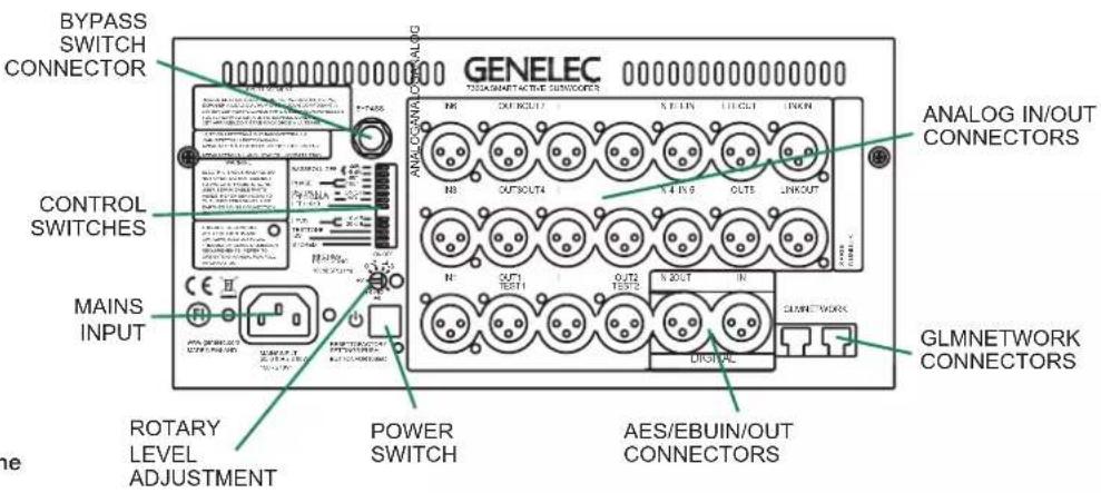
BYPASS SWITCH CONNECTOR GENELEC 72016MNET-ACTIVE CONNECTORS ANALOG IN/OUT CONNECTORS CONTROL SWITCHES MAINS INPUT ROTARY LEVEL ADJUSTMENT POWER SWITCH AES/EBUIN/OUT CONNECTORS GLMNETWORK CONNECTORSFigure 1. Connector panel of the 7360A. The 7370A is similar.
- Y-cables from the source to the subwoofer's IN connector and the monitor's signal input.
- Signal sources with dual outputs for each channel.
Use With GLM ^TM
Control Network
Subwoofers are fully compatible with Genelec Loudspeaker Manager GLM™ and the proprietary Genelec monitor control network and Genelec SAM monitors. Using the GLM control method unleashes the full room compensation power in the subwoofer, with 20 parametric room compensation filters. This level of room compensation detail is only available when the GLM is used. Use with the GLM™ network is described in the GLM System Operating Manual.
System setup
Although the subwoofer can be used without the GLM™ software and control network, they only reach their full potential when set up and calibrated using the GLM™ software. Genelec Loudspeaker Manager GLM™ and the proprietary Genelec monitor control network offer automated acoustic equalization and alignment for any reproduction system from simple stereo to very complex 3D immersive setups including also one or more subwoofers. GLM setup is fast and accurate and can precisely address the typical narrow-band low frequency mode resonances of a room, or typical radiation load frequency response compensation. The settings can be controlled with a computer or be permanently stored in the monitors to make the setup available at all times even
flowchart
graph TD
    A["Computer"] --> B["GLM ADAPTER"]
    C["USB Cable"] --> B
    D["Microphone"] --> B
    B --> E["GLM NETWORK CABLE"]
    F["Subwoofer"] --> G["MONITORS"]
    G --> H["Monitor"]
    I["USBCABLE"] --> B
    J["COMPUTER RUNNING GLM S OFTWARE"] --> B
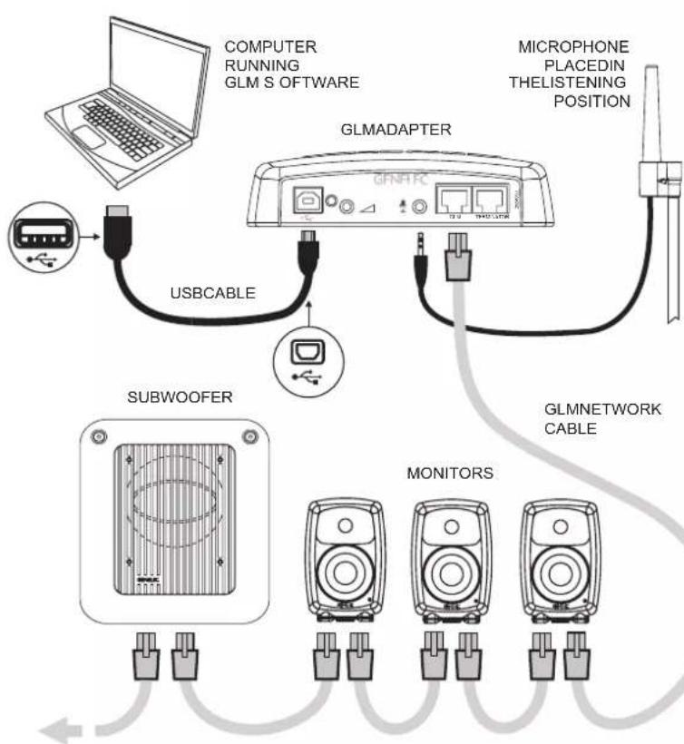
Figure 2. GLM Network cabling. Audio cabling not shown.
when a computer is not in use. Genelec recommends setting up SAM monitoring systems using GLM. You can find a detailed description of the setup and the use of GLM ^TM in the GLM ^TM System Operating Manual.
The setup is fast and consists of the following steps:
- Connect a CAT5 (RJ45) cable between each monitor (and subwoofer) and finally to the control network input of the GLM Adapter device (see Figure 1).
- Connect the GLM Adapter device to computer USB connector.
• Using a microphone stand, place the Genelec measurement microphone at the listening location with the microphone
pointing upwards and the microphone top at the height of the engineer's ear. The microphone is a part of the GLM User Kit.
- Connect the microphone cable to the microphone input in the GLM Adapter device.
- Download the GLM software at the Genelec web site (www.genelec.com).
• Install the GLM software and follow the instructions in the software to measure and set up your system. - If you plan to not use a computer for controlling the monitors, use the GLM software to write the setting into the monitors (use menu item "Store | Store the Current Group Settings...").
While the GLM network is disconnected the settings stored using the Genelec Loudspeaker Manager software can be can be retrieved and activated by setting the STORED switch ON.
With GLM active and controlling the subwoofer, the use of analog or digital inputs is forced by the "Input Type" in the Group. In standalone manual mode, AES/EBU digital signal will override analog signal if valid digital clock is detected.
Using standalone Stored Settings, the input type defined by the Group is used.
Use Without GLM
Cabling
These subwoofers can be easily set up using the fixed 85 Hz analogue crossover filter. This fixed crossover filter is on as a factory setting and highpass filters the analogue outputs on the subwoofer. When using this method, run each signal cable first to the subwoofer. Then, run the respective output to the monitor. This monitor feed signal is highpass filtered at 85 Hz.
When using the LFE signal, run the LFE signal to the subwoofer LFE in connector.
Control Switches
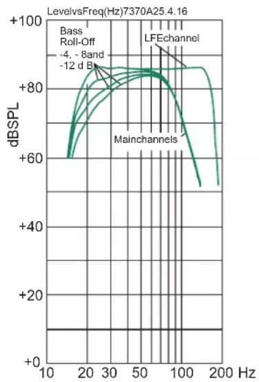
BASS ROLL-OFF controls compensate for the very low frequency boost, reducing the 20 Hz level in 4 dB steps. The settings add to a total of 12 dB attenuation. Setting both switches to "OFF" obtains a flat response.
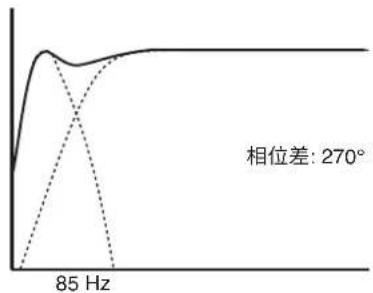
PHASE switches can put the subwoofer in phase with a selected main monitor. Incorrect phase alignment can cause a drop
line
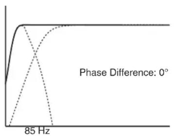
| Frequency | Phase Difference | | --------- | ---------------- | | 0 | 0 | | 85 Hz | 0 |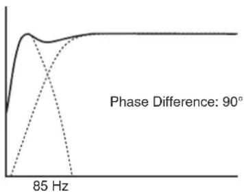
line
| Frequency | Phase Difference (°) | | --------- | -------------------- | | 85 Hz | 90 |
line
| Frequency | Phase Difference (°) | | --------- | -------------------- | | 85 Hz | 180 |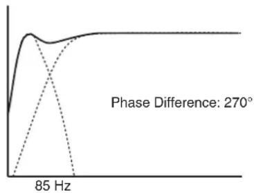
line
| Phase Difference | Value | | ---------------- | ----- | | 270° | Peak |Figure 3. The effect of phase difference between the subwoofer and the main monitors
in level at the crossover frequency. See chapter "Setting the Phase Switches."
Digital LFE switch selects the low pass frequency for the subframe selected to reproduce LFE (see "LFE CHANNEL" below). The frequencies are 85 Hz for "OFF" and 150 Hz for "ON."
LFE CHANNEL A/B selects which subframe carries the LFE signal. "ON" for A, "OFF" for B. If A is selected for LFE, the B subframe is assumed to carry main channel audio.
LFE +10 dB function adds +10 dB of gain. See chapter "Using the LFE +10 dB function."
LEVEL switches scale down the subwoofer output level. The switch settings add up and combine with the rotary level adjustment control.
TEST TONE switch activates the 85 Hz test tone used for calibrating the phase. See chapter "Manual Phase Adjustment Method"
ISS switch activates the signal sensing automatic energy saving function.
STORED switch selects the settings stored inside the memory of the subwoofer and settings made by the subwoofer's controls. The stored settings are set using the GLM Loudspeaker Manager Software and the GLM control network and provide superior functionality compared to the subwoofer's own controls.
Connector Panel Light
Normally, the light on the connector panel is green, indicating normal operational mode. Red colour indicates amplifier clipping and yellow indicates thermal overload. If the red or yellow warning light appears, turn down the level.
Setting the Phase Switches
Incorrect phase alignment between main monitors and subwoofer causes a drop in the frequency response of the whole system at the crossover frequency. Figure 3 shows the effect of phase difference to the frequency response.
The phase difference between the main monitors and subwoofer at the listening position depends on the position of the subwoofer, so the phase adjustment should be done only after the preferred position is found and subwoofer and monitor levels have been aligned. GLM software control adjusts the phase automatically, but if GLM is not available, the following manual phase matching can be applied.
Manual Phase Adjustment Method
Genelec 7360A and 7370A subwoofers are equipped with a built-in 85 Hz frequency test tone generator for phase alignment. The test tone generator is connected to the subwoofer's "TEST 1" output. Connect temporarily a monitor to this output for manual phase alignment.
Power up the system and set the TEST TONE switch to "ON." Now you can hear an 85 Hz test signal from the subwoofer and the main monitor connected to the center channel output.
- Toggle the -180^ phase switch on and off, and set it to the position which gives the lowest sound level at the listening position.
- Next toggle the -90^ phase switch on and off, and again set it to the position which gives the lowest sound level.
- Finally, set the -180^ phase switch to the opposite setting and deactivate the test signal. The phase adjustment is now complete.
Using the LFE +10 dB Function
Dolby Digital and DTS encoding formats present the LFE channel with +10 dB gain relative to the main channels. Surround sound decoders may automatically add +10 dB of LFE gain to restore the level balance.
The “LFE +10 dB” function can add the +10 dB of gain to the LFE channel in the production stage if it is not already done by the source connected to the monitoring system. Switching the “LFE +10 dB” switch to the “ON” position activates the function. If the LFE output is at a 10 dB higher level than other (non-LFE) channels, this switch should be set to “OFF”.
The "LFE +10 dB" function should not be used in the following cases:
- If the +10 dB LFE gain is already implemented by another device, for example, a surround sound processor or the output matrix of a mixing console.
- When producing an audio format that does not require the use of +10 dB gain on the LFE channel.
Additional Information
Positioning Subwoofer in Room
The location of the subwoofer can affect the frequency response and sound level dramatically particularly when the room acoustic effects are strong. Even small changes in a subwoofer's location can make a marked difference in the frequency response. To begin, place the subwoofer at the front wall slightly offset from the room center line. Often methodical experimentation is needed to find the location giving the flattest frequency response at the listening location. Usually the subwoofer is placed close to a wall as this usually creates the highest output. Positioning the subwoofer close to a corner will boost the bass level at lower frequencies and may also cause asymmetrical spatial imaging. Measured from the subwoofer's driver the recommended distance to a wall is less than 0.6 m (24 in). Cancellations from the wall are then avoided.
Operating Environment
These subwoofers are designed for indoor use only. The permissible ambient temperature is 15-35 degrees Celsius (50-95°F) and relative humidity 20% to 80% (non-condensing). When the product has been stored or transported in cool environment and is taken into a warm room, wait 0.5-1 hours before opening packing to prevent condensation of humidity before connecting to mains power.
Minimum Clearances
Do not cover the grille or place the subwoofer so that there is less than 0.1 m (4 in) of free space in front of the grille. The space must be ventilated or sufficiently large to dissipate heat so that the ambient temperature does not rise above 35 degrees Celsius (95°F). Make sure that the space under the subwoofer allows air flow. Thick carpets may block ventilation needed for cooling the electronics. The reflex port opening should have a clearance of at least 7.5 cm (3 in) to ensure functioning of the reflex port.
Flush Mounting
When the subwoofer is flush mounted in a wall or cabinet, ensure unrestricted airflow in the reflex port and amplifier cooling.
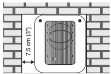
text_image
7,5 cm (3")Figure 4. Flush mounting the subwoofer. Note the clearance needed on the reflex port side.
Make the recess 7.5 cm (3 in) wider than the subwoofer. Place the subwoofer to the right side of the recess if the driver is facing the room. This leaves sufficient free space at the reflex port side. The height and depth of the recess should not be much bigger than needed for ventilation as this may cause unwanted acoustic effects.
Using Multiple Subwoofers
Multiple Genelec 7360A or 7370A subwoofers can be coupled together in high SPL applications. The necessary cabling is different for digital and analog signals.
Digital Cabling
Run a signal cable from the AES/EBU OUT connector of the first subwoofer in the chain to the AES/EBU IN connector of the next subwoofer. Check that the Digital LFE and LFE Channel A/B control switches have the same settings in all subwoofers in the chain.
Analog Cabling
When daisy-chaining multiple subwoofers with analog signals, run a cable from the Link Out connector to the next subwoofer's Link In connector. When using the LFE signal, also run a cable from the LFE Out to the next subwoofer's LFE In.
Control Switch Settings
When Using Multiple Subwoofers
When using GLM and its AutoCal function for calibration, no manual adjustments on the control switches are necessary. If GLM is not available, manual adjustments are needed.
-
Calibrate the subwoofers one by one with all other subwoofers in the chain switched off. Start with the first subwoofer.
-
First calibrate the level between the subwoofer and all main monitors using the rotary level adjustment trimmer on the subwoofer and suitable test signals.
- Adjust the phase of the first subwoofer as instructed in the chapter "Manual Phase Adjustment Method".
- Repeat phases 1 to 3 with all other subwoofers in the chain, one by one.
- When two subwoofers connected in this way are positioned close to one another, bass level increases by 6 dB. Three subwoofers give an SPL increase of 9.5 dB and four subwoofers 12 dB compared to a single subwoofer. In order to match the SPL level of the complete subwoofer chain with the main monitor system, reduce the level of all subwoofers in the chain accordingly.
Maintenance
There are no user serviceable parts inside the subwoofer. Maintenance or repair must only be done by a Genelec certified service.
Guarantee
Genelec guarantees the subwoofers for two years against manufacturing faults or defects altering performance. Refer to the reseller for full sales and guarantee terms.
Safety Considerations
The 7360A and 7370A have been designed in accordance with international safety standards. To ensure safe operation, the following warnings and precautions must be observed:
- Servicing and adjustment must only be performed by a Genelec certified service.
- The subwoofer enclosure must not be opened.
- Do not use this product with a mains cable or mains outlet having no protective earth (potential equalizing) connection as doing so may result in personal injury.
• To prevent fire or electric shock, do not expose the product to water or moisture - Do not place objects filled with liquid, such as vases, on the subwoofer or near it.
- The amplifier is not completely disconnected from the mains power unless the mains cable is removed from the amplifier or the mains outlet.
line
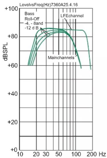
| Frequency (Hz) | dBSPL | | -------------- | ----- | | 10 | +60 | | 20 | +80 | | 30 | +85 | | 50 | +88 | | 100 | +85 | | 200 | +60 |Figure 5. The curves above show the main channel's frequency response with 85 Hz lowpass filtering, the frequency response of the LFE channel and the effect of the Bass Roll-Off adjustment to the response of the 7360A.
- Free flow of air behind and around the subwoofer is necessary to maintain sufficient cooling. Do not obstruct airflow around the subwoofer.
• These subwoofers are capable of producing sound pressure levels in excess of 85 dB, which may cause a permanent hearing damage.
Compliance to FCC Rules
This device complies with part 15 of the FCC Rules. Operation is subject to the following two conditions:
- This device may not cause harmful interference, and
- This device must accept any interference received, including interference that may cause undesired operation.
Note: This equipment has been tested and found to comply with the limits for a Class B digital device, pursuant to part 15 of the FCC Rules. These limits are designed to provide reasonable protection against harmful interference in a residential installation. This equipment generates, uses and can radiate radio frequency energy and, if not installed and used in accordance with the
line
| Frequency (Hz) | dBSPL | | -------------- | ----- | | 10 | +60 | | 20 | +80 | | 30 | +85 | | 50 | +90 | | 100 | +85 | | 200 | +60 |Figure 6. The curves above show the main channel's frequency response with 85Hz lowpass filtering, the frequency response of the LFE channel and the effect of the Bass Roll-Off adjustment to the response of the 7370A.
instructions, may cause harmful interference to radio communications. However, there is no guarantee that interference will not occur in a particular installation. If this equipment does cause harmful interference to radio or television reception, which can be determined by turning the equipment off and on, the user is encouraged to try to correct the interference by one or more of the following measures:
- Reorient or relocate the receiving antenna.
- Increase the separation between the equipment and receiver.
- Connect the equipment into an outlet on a circuit different from that to which the receiver is connected.
- Consult the dealer or an experienced radio/TV technician for help.
Modifications not expressly approved by the manufacturer could void the user's authority to operate the equipment under FCC rules.
SPECIFICATIONS
| Model 7360A 7370A | ||
| Lower cut-off frequency -6 dB 19 Hz 19 Hz | ||
| Upper cut-off frequency -6 dB (main channel/LFE) 100 Hz/150 Hz 100 Hz/1 | 50 Hz | |
| Driver 250 mm (10 in) | (magnetically shielded) | 305 mm (12 in)(no magnetical shielding) |
| Harmonic distortion at 1 m on axis in half space, 30 to 85 Hz 2nd ≤ 3% @ 90 dB SPL3rd ≤ 2% @ 90 dB SPL | 2nd ≤ 3% @ 95 dB SPL3rd ≤ 3% @ 95 dB SPL | |
| Maximum short term sine wave SPL output averaged from 30 to 85 Hz, measured in half space at 1 meter | ≥ 109 dB SPL ≥ 113 dB SPL | |
| Maximum peak SPL output with random pink noise, measured in half space at 1 meter | ≥ 114 dB SPL ≥ 118 dB SPL | |
| Self generated noise at 1 m on axis (A-weighted) < 5 dB | ||
| Weight 27 kg 48 kg | ||
| Dimensions H x W x D 527 x 462 x 365 mm | 20^3/_4 × 18^3/_16 × 14^3/_8 in | 625 x 555 x 496 mm 24^5/_8 × 21^7/_8 × 19^1/_2 in |
AMPLIFIER SECTION
| Short term amplifier output power(Long term output power is limited by driver unit protection circuitry) | 300W 400W | |
| Amplifier system THD at nominal output | ≤0.01% | |
| Mains voltage | 100-240 VAC 50/60 Hz | |
| Power consumptionStandby, ISS activeIdleFull output, peak | <1 W15 W300 W | <1 W20 W400 W |
SIGNAL PROCESSING SECTION
| Analog signal input connector XLR female, balanced 10 kOhm | pin 1 gnd, pin 2 non-inverting, pin 3 inverting |
| Maximum analog input signal | +25.0 dBu |
| Analog input sensitivity (100 dB SPL at 1 m) rotary level adjustment | +12 to -6 dBu |
| Digital signal input connector XLR female 110 Ohm | AES/EBU Single Wire |
| Digital signal output / Thru connector XLR male 110 Ohm | AES/EBU Single Wire |
| Digital audio input | |
| Word length | 16 - 24 bits |
| Sample rate | 32 - 192 kHz |
| Digital input sensitivity(100 dB SPL at 1 m) rotary level adjustment | -30 dBFS |
| Subsonic filter (18 dB/octave) below | 19 Hz |
| Control network | |
| Type | Proprietary GLM ^TM network |
| Connection | 2 RJ45, CAT5 cables |
| GLM ^TM software frequency response adjustment parametric notch filters | 20 |
| System calibration | Genelec GLM AutoCal ^TM |
| Crossover subwoofer/subwoofer output channels | |
| Centralized Bass Management | Subwoofer: low pass 85 Hz, output: high pass 85 Hz |
| Distributed Bass Management (GLM control only) | Subwoofer: low pass 50-100 Hz, output: no filtering |
| LFE cutoff | 150 Hz |
| Midband rejection >400 Hz | ≥ 50 dB |
| Bass Roll-Off control operating range in 4 dB steps | 0 to -12 dB at 20 Hz |
| Phase matching control | 90° steps with dip switch controls |
| 15° steps with GLM control |
Genelec Document D0134R001a Copyright Genelec Oy 7.2016. All data subject to change without prior notice
GENELEC®
International enquiries:
Genelec. Olvitie 5
FIN-74100, lisalmi, Finland
Phone +358 17 83661
Fax +358 17 812 267
Email genelec@genelec.com
In the U.S. please contact:
Genelec, Inc., 7 Tech Circle
Natick, MA 01760, USA
Email sweden@genelec.com
In China please contact:
Beijing Genelec Audio Co.Ltd
B33 - 101
Universal Business Park
No. 10 Jiuxianqiao Road
Chaoyang District
100015 Beijing, China
Phone +86 400 700 1978
Email genelec.china@genelec.com
www.genelec.com
In Japan
Genelec Japan Inc.
2-22-21 Akasaka, Minato-ku
07-0052, Tokyo
Phone +81-3-6441-0591
genelec.japan@genelec.com
Email genelec.japan@genelec.com
-

[Non-Text]
[Non-Text]
[Non-Text]
[Non-Text]
[Non-Text]
[Non-Text]
[Non-Text]
[Non-Text]
[Non-Text]
-
[Non-Text]
[Non-Text]
[Non-Text]
[Non-Text]
[Non-Text]
[Non-Text]
[Non-Text]
[Non-Text]
[Non-Text]
[Non-Text]
[Non-Text]
[Non-Text]
[Non-Text]
[Non-Text]
[Non-Text]
[Non-Text]
[Non-Text]
[Non-Text]
[Non-Text]
[Non-Text]
[Non-Text]
[Non-Text]
[Non-Text]
[Non-Text]
[Non-Text]
[Non-Text]
[Non-Text]
[Non-Text]
[Non-Text]
[Non-Text]
[Non-Text]
[Non-Text]
[Non-Text]
[Non-Text]
[Non-Text]
[Non-Text]
[Non-Text]
[Non-Text]
[Non-Text]
[Non-Text]
真力7360A and 7370A智能有源超低音箱
介绍
line
| Frequency | Solid Line Value | Dashed Line Value | | --------- | ---------------- | ----------------- | | 85 Hz | 0 | 0 |
line
| Frequency | Solid Line Value | Dashed Line Value | | --------- | ---------------- | ----------------- | | 85 Hz | Peak | Low | | High | ~1.0 | ~0.5 |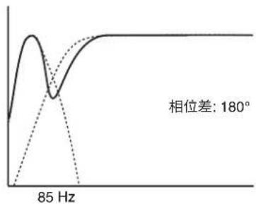
line
| Frequency | Value | | --------- | ----- | | 85 Hz | 180° |