
1238A - Monitor GENELEC - Free user manual and instructions
Find the device manual for free 1238A GENELEC in PDF.


| Product Type | Active Studio Monitor (Three-Way DSP) |
| Brand | Genelec |
| Model | 1238A |
| Frequency Response (-3 dB) | 33 Hz - 21 kHz |
| Frequency Response Accuracy | ±2.5 dB (35 Hz - 20 kHz) |
| Maximum Short Term SPL (1 m, half space) | >121 dB SPL |
| Maximum Peak SPL (pair, 2 m, music) | >124 dB SPL |
| Drivers | Woofer: 385 mm (15 in) cone Midrange: 125 mm (5 in) cone Tweeter: 25 mm (1 in) metal dome |
| Amplifier Power (Short Term) | Bass: 500 W, Mid: 250 W, Treble: 200 W |
| Amplifier THD at Nominal Output | <0.01% |
| Signal-to-Noise Ratio | >115 dB (all bands, referred to full output) |
| Analog Input | XLR female, balanced, 10 kOhm, max +25 dBu |
| Digital Input | AES/EBU XLR female, 110 Ohm, 16-24 bit, 32-192 kHz |
| Control Network | Proprietary GLM, 2 x RJ45 (CAT5) |
| Mains Voltage | 100-240 VAC, 50/60 Hz |
| Power Consumption | Standby: <0.5 W, Idle: 25 W, Full Output: 750 W |
| Dimensions (Enclosure HxWxD) | 810 x 480 x 420 mm (32 x 19 x 16.5 in) |
| Weight (Monitor with Amplifier) | 57 kg (126 lb) |
| Weight (Amplifier Only) | 6 kg (13 lb) |
| Mounting Options | Free-standing or flush-mount; amplifier detachable for 19" rack |
| Key Features | GLM AutoCal, DCW waveguide, ISS auto standby, overload protection |
| Included Accessories | Mains cable, GLM network cable, operating manual |
| Cleaning | Wipe with a soft dry cloth. Do not use liquids or solvents. |
| Safety Notes | Hearing hazard above 85 dB SPL. Do not open enclosure. Use with protective earth. |
Frequently Asked Questions - 1238A GENELEC
User questions about 1238A GENELEC
0 question about this device. Answer the ones you know or ask your own.
Ask a new question about this device
Download the instructions for your Monitor in PDF format for free! Find your manual 1238A - GENELEC and take your electronic device back in hand. On this page are published all the documents necessary for the use of your device. 1238A by GENELEC.
USER MANUAL 1238A GENELEC
natural_image
Exterior view of a black GENELEC audio speaker tower with visible sound waves and control knobs (no text or symbols on body)Genelec 1237A and 1238A Operating Manual
Introduction
Congratulations and a thank-you for the purchase of this Genelec Smart Active Monitoring (SAM) Series DSP monitor loudspeaker.
This product should be set up using the fully automatic process in the Genelec Loudspeaker Manager GLM™ software. There are no setup controls on the amplifier panel.
This manual describes the basic setup of the monitor for use with the GLM software, as well as use in the Stand-alone mode without the GLM software in use or permanently connected for computer control.
Each monitor is supplied with a mains cable, one GLM control network cable, and an operating manual.
System
The Genelec 1237A and 1238A are three-way monitoring systems for medium sized control rooms. They perform well as free-standing monitors as well as flush-mounted in control room walls. They are suited for recording, film and video post-production, broadcast monitoring as well as for mastering.
The unique Directivity Control Waveguide™ (DCW™) technology by Genelec provides excellent stereo imaging and neutral frequency response even in difficult acoustics.
With program material at a 2 meter listening distance, the fast low distortion amplifiers drive a stereo system to peak sound levels in excess of 122 dB SPL (1237A) or 124 dB SPL (1238A).
The 1237A and 1238A are fully compatible with Genelec Loudspeaker Manager GLM™ and proprietary Genelec control network. They can be used with 8200-series SAM monitors and 7200-series SAM subwoofers in the same network.
Drivers and Cabinet Construction
The 1238A reproduces low frequencies with a 385 mm (15 in) woofer in a 110 litre bass reflex enclosure. The 1237A features a 305 mm (12 in) woofer in a 65 litre bass reflex enclosure. Both monitors use the same proprietary 130 mm (5 in) direct radiating mid-range driver, and a 25 mm (1 in) metal dome tweeter, both acoustically loaded by the proprietary Directivity Control Waveguide. All drivers are magnetically shielded.
Amplifiers and Signal Processing
The 1237A and 1238A use the RAM-L amplifier unit. The RAM-L is mounted with vibration absorbers in the rear of the monitor enclosure, and can also be detached and mounted to a 19 inch rack. Digital signal processing in the RAM-L amplifier unit is done with high precision algorithms, and includes driver and amplifier overload protection. The room response compensations include highly flexible parametric filters, level alignment, and acoustic delay compensation. These allow accurate matching to all console output sections and room acoustics.
Mounting Considerations
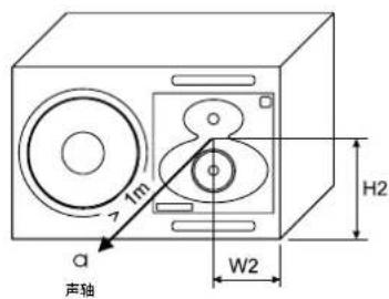
Place monitors so that their acoustic axes are aimed towards the listening position (see Figures 1 and 2). Place monitors with left-right symmetry and at an equal distance from the listening position. Acoustic reflections from objects close to monitors and the listening position can cause colouration and blurring of the sound image. Symmetrical positioning of reflective objects maintains good stereo imaging. When soffit (flush) mounting, the wall surface should extend to the monitor, forming a continuous surface.
Minimum Clearances
The minimum clearance is 5 cm (2 in) behind, above and on both sides of the monitor, when the RAM-L amplifier is mounted on the enclosure. The ambient temperature around the amplifier must not exceed 35 degrees Celsius (95°F). When soffit mounting, sufficient ventilation should be a arranged behind the monitor. This may require forced ventilation around the RAM-L amplifier.
When the RAM-L amplifier is mounted in a 19 in rack, the minimum free space is 1U both above and below the amplifier and both sides of the amplifier fully open to enable free movement of air. Use the included rack mount front plate to ensure sufficient space above and below the amplifier.
When the RAM-L is mounted on a table, shelf or similar solid surface, there must be a free space of at least 250 mm (10 in) above and 10 cm (4 in) on both sides of the amplifier. Free air flow must be possible in the front side of the amplifier.
Set-up and Use
Monitor calibration and setup
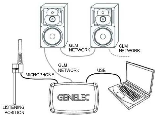
The 1237A and 1238A are set up using the GLM software. The setup is fast and consists of the following steps:
- Run a CAT5 (RJ45) cable from the monitor control network to the next monitor.
- Run the final cable to control network input of the GLM Adapter device.
- Connect the GLM Adapter device to your computer USB connector. The cable is a part of the GLM User Kit.
- Place the Genelec measurement microphone at the listening location of the engineer, on a stand, with the microphone pointing upwards and the microphone top at the height of the engineers ear in normal working position. The microphone is a part of the GLM User Kit.
- Run the microphone cable to the micro-phone input in the GLM Adapter device.
- Download GLM software at the Genelec web site (www.genelec.com). Install the GLM software.
- Follow the GLM software instructions to measure and set up your monitors.
- If you plan to not use a computer for controlling the monitors, use the GLM software to write the setting into the monitors ("Store the Settings").
Recommendations for AES/EBU Audio
For a digital input signal of -30 dB FS, the 1237A and 1238A monitors will produce a 100 dB sound level (SPL) at 1 meter distance, in free space. The sensitivity of the monitor system is set using the GLM software.
It is advantageous to keep the maximum incoming digital audio signal level high, near to 0 dBFS. It may be useful to lower the internal GLM level control. This enables maintaining high digital resolution in the digital source.
Single-wire mode of AES/EBU is the
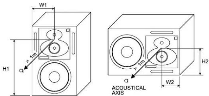
| H1 mm (In) W1 | mm (In) H2 mm (In) | W2 mm (In) | ||||||
| 1237A 540 | (21 | ^1/_4 in) | 200 (7 | ^7/_8 in) | 230 (9 | ^1/_16 in) | 170 (6 | ^11/_16 in) |
| 1238A 650 | (25 | ^5/_8 in) | 240 (9 | ^1/_2 in) | 282 (11 | ^1/_8 in) | 202 (7 | ^15/_16 in) |
Figure 1. The location of the acoustic axis.
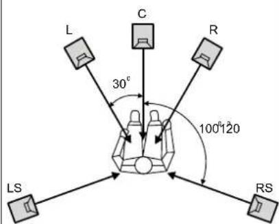
Figure 2. Recommended placement and alignment of monitors in a 5-channel system (ITU-R BS.775-1)
flowchart
graph TD
    A["LISTENING POSITION"] --> B["MICROPHONE"]
    B --> C["GENELEC"]
    C --> D["USB"]
    D --> E["Laptop"]
    F["GLM NETWORK"] --> C
    G["GLM NETWORK"] --> C
    H["GLM NETWORK"] --> C
Figure 3. GLM network cabling
analog input signal. The digital audio AES/EBU input is selected automatically when a valid digital audio signal is presented. Use GLM software to define the AES/EBU sub-frame to monitor.
"DIGITAL THRU AES/EBU" Connector
This output carries an unaltered copy of the digital audio signal and can be used for daisy-chaining the signal up to three additional SAM monitors or subwoofers.
"ANALOG IN" Connector
The maximum input level of the analog input is +25.0 dBu. The analog input must not be overloaded, otherwise distortion will result. When the maximum input is exceeded, the enclosure front panel light turns red, indicating the overload.
The sensitivity of the monitor system is set using the GLM software. Coming from the factory, the analog input is set to the highest sensitivity, resulting in a sound output of 100 dB SPL for a -6 dBu analog input signal.
"CONTROL NETWORK" Connectors
The RJ-45 sockets connect the monitor to the proprietary Genelec Loudspeaker Manager™ (GLM™) network. Do not connect to Ethernet LAN.
"Loudspeaker Connectors" Group
These connectors are used when the RAM-L amplifier is mounted separately in an equipment rack.
1. "LED" Connector
This RJ-45 socket is a connection for
default and the older dual-wire mode is automatically detected if used at the source.
The standard AES/EBU cable carries two channels of audio, called A and B. As a default, both A and B subchannels are reproduced by the monitor. GLM software is used to set up the monitor to specific channel assignments.
RAM-L Amplifier Power Button
The power button in the middle of the RAM-L amplifier front panel controls several functions.
A short press of the power button turns RAM-L on or off. Turning on, the power button light flashes rapidly, and lights on steadily when the turn-on has been completed.
Testing modes are explained later in this manual.
Setting ISS™
The Intelligent Signal Sensing (ISS) puts the monitor to a power-saving stand-by mode automatically. The factory setting for ISS is "OFF." The ISS can be activated using the GLM software (see Figure 5). When ISS is active, if no audio signal is sensed during the selected time, the monitor powers down. The monitor will power up again once a signal is detected. The ISS setting is applied to all ISS-enabled monitors in the currently selected Setup.
Connections
"MAINS INPUT" Connector
Connect to the mains supply.
"DIGITAL IN AES/EBU" Connector
The monitor defaults to reproducing an
the front panel warning LED.
-
"Woofer" Connector A standard four-pole Speakon cable connects to the woofer.
-
Midrange/Tweeter" Connector A standard four-pole Speakon cable connects to the the midrange and tweeter.
Front Panel Light Functions
Green light on the DCW panel of a 1237A or 1238A enclosure indicates normal operation. A yellow light indicates certain activities when the GLM control software is used. The light turns red in an overload condition. The overload light (red) is activated by several events:
- Exceeding the maximum input of the analog input
- Reaching close to the digital input maximum (high likelihood of digital clipping)
- Overload of drivers or amplifier, or clipping in the power amplifier
- An error detected in the AES/EBU audio data
If a red warning light appears on the monitor enclosure, turn the source level down. Ensure that there are no bit errors in the AES/EBU digital audio data transmission.
Mounting RAM-L Amplifier in a 19 Inch Rack
The RAM-L amplifier can be removed from the enclosure and installed in a standard 19 inch rack. The rack mount components (front plate, brackets, screws) are included with the monitor.
Preparation for rack mount is done with the following process:
- Remove all signal cables and the mains cable from the amplifier.
- Remove the two screws attaching the amplifier to the vibration isolating mounts at the left top and bottom.
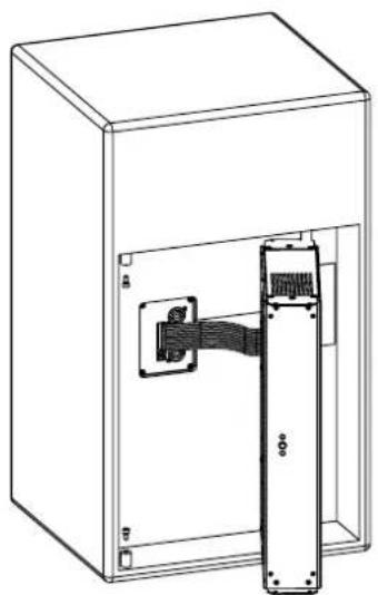
- Pull out the left side of the amplifier (see figure 6).
- Detach the flat cable from the enclosure.
- Undo the two screws on the right side isolating mounts. Remove the amplifier.
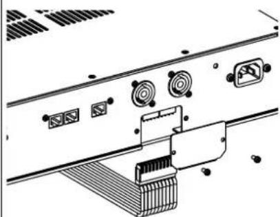
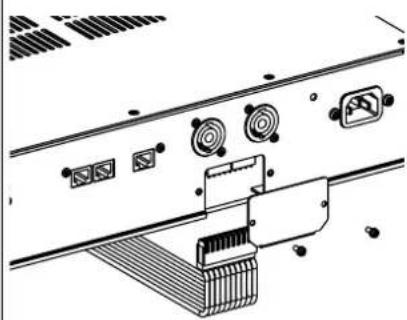
- Remove the cover of the flat cable connector (see figure 7)
- Pull out (detach) the flat cable from the amplifier unit.
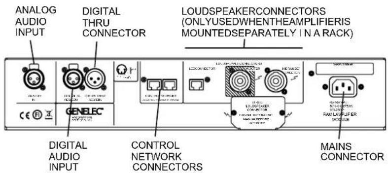
Figure 4. Connector panel of the RAM-L amplifier.
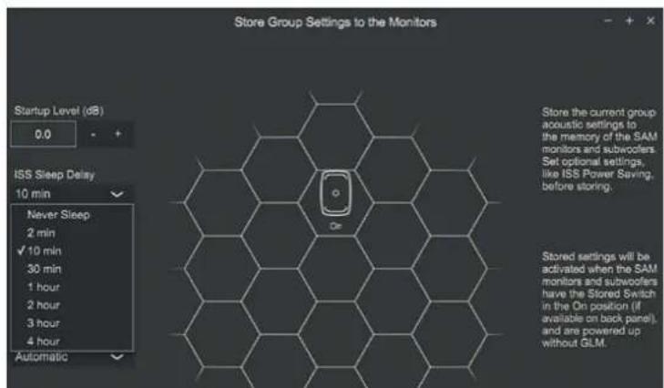
Figure 5. Selecting ISS setting.
- Reattach the cover of the flat cable connector.
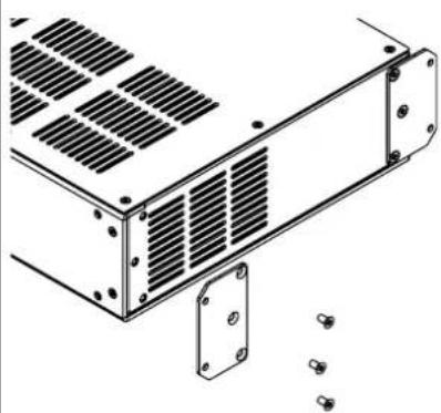
- Remove the front mounting ears (see figure 8).
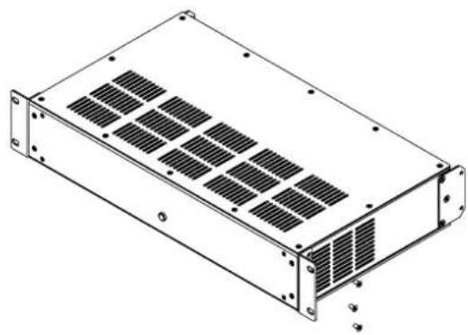
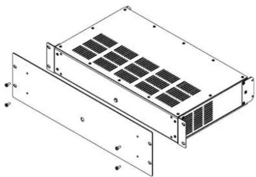
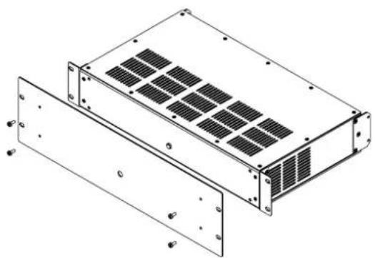
- Attach two angled rack mount brackets (included). Attach the front plate (included) (see figures 9 and 10).
- Attach the amplifier to a 19 inch rack.
- Remove the plastic cover from the RJ45 connector. Attach two Speakon cables, and one RJ45 cable (LED CONNECTOR) between the amplifier and the cabinet.
- Attach signal cables and the mains cable.
Flush Mounting the Monitor Enclosure
Flush mounting offers acoustical benefits. No cabinet edge diffraction will occur. Low frequency reflections from the wall behind the monitor can be avoided. The monitor's acoustical axis (Figure 1) should point to the seated listening position. The wall in which the monitors are mounted should be stiff and
| Cable gauge Max. length | |
| 2.0 mm ^2 (14 AWG) 30 m (100 ft) | |
| 3.3 mm ^2 (12 AWG) 40 m (130 ft) | |
| 5.3 mm ^2 (10 AWG) 60 m (200 ft) |
Table 1. Recommended cable thicknesses for different lengths of signal cable
heavy. The monitors should not be mounted too high (maximum tilt angle < 15 degrees).
A space 50 to 100 mm (2 to 4") wide can be left around the monitor but this space should be covered with a panel in the front. Leave a gap of 5 to 10 mm ( 14 to 12 ") between the monitor and the panel. Fill this gap with a soft rubber gasket (see figure 14). The monitor should be mounted on vibration isolators. The resonant frequency of movement for the mounted monitor should be between 2 to 8 Hz.
An empty cavity in the wall should be filled with absorbent mineral wool or foam plastic. A wooden wall structure must be heavily braced (see figure 11). In a solid (e.g. con-
natural_image
Technical line drawing of an open electrical enclosure with a vertical cylindrical component inserted (no text or symbols)Figure 6. Pull out the left side of the amplifier and detach the flat cable from the enclosure.
natural_image
Technical line drawing of a rectangular electronic device with internal grating and mounting flanges (no text or symbols)Figure 9. Attach the angled rack mount ears.
natural_image
Technical line drawing of a rectangular electronic device with mounting flanges and internal grid structure (no text or symbols)Figure 10. Attach the front plate.
natural_image
Technical diagram of a computer monitor rear panel with indicator lights and ports (no text or labels)Figure 7. Remove the flat cable cover plate and detach the flat cable connector. Reattach the cover plate.
crete) wall structure, the space around the cabinet should be filled with absorbent mineral wool or sand bags (see Figure 12).
Ensure that the cabinet is flush with the surface of the wall. If a decorative cloth frame is used the edges adjacent to the monitors must be less than 20 mm (3/4 in) deep. The cloth must be acoustically transparent. Genelec-approved cloth grilles are available.
Testing Mode
Once on, when the power button is pressed for a long time, the RAM-L enters a mode for system testing. This special mode is intended for system debugging and testing. When the RAM-L is turned off, the special mode is reset. Upon restarting the RAM-L the current standard settings stored by GLM software are restored.
Test mode selection blinks the power button light (see Table 2). A special mode is activated by a long press on the power button. In a special mode the power button light remains on but blinks off 1-4 times indicating the mode currently selected.
The testing modes are not intended for continued operation. Use GLM software to set up permanent settings for 1237A and 1238A.
Safety Considerations
The 1237A and 1238A have been designed in accordance with international safety standards. To ensure continued safe operation and to maintain the monitor under safe operating conditions, the following warnings and precautions must be observed:
- Servicing and adjustment must only be performed by qualified service personnel. The monitor enclosure or the amplifier enclosure must not be opened.
- Do not use this product with a mains cable with no protective earth conductor, or a mains connection without the protective earth contact, as this may lead to personal injury.
- To prevent fire or electric shock, do not expose the unit to water or moisture.
- Do not place any objects filled with liquid, such as vases or water pipes on the monitor or near it.
- Note that the amplifier is not completely disconnected from the AC mains service unless the mains power cord is removed from the amplifier or the mains outlet.
- Free flow of air behind the monitor is
natural_image
Technical line drawing of a mechanical housing component with mounting flanges and bolt holes (no text or symbols)Figure 8. Remove the front mounting ears.
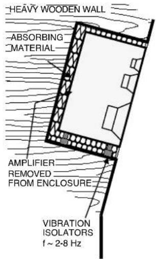
Figure 11. Flush mounting the monitorin a wall constructed of wood
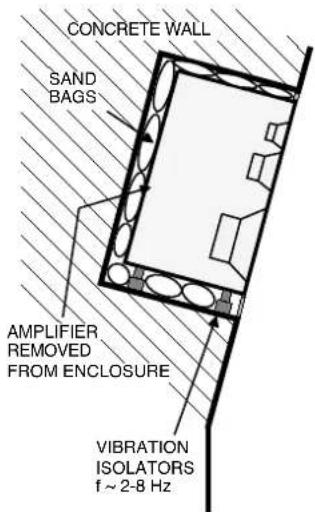
Figure 12. Flush mounting the monitor in a wall constructed of concrete
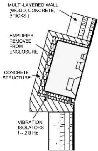
Figure 13. Flush mounting the monitor in a wall constructed of a combination of materials.
| Button press Function Notes | ||
| Short press Power on, power off | ||
| Long press Enter special mode, | exit special mode | Press longer than 5 seconds |
| Special mode: one short press M | Mode 1: AES/EBU channel A selected, room-related calibration in use | Power button light blinks once every few seconds |
| Short press advances Mode 2: A | ES/EBU channel B selected, room-related calibration in use | Power button light blinks twice every few seconds |
| Short press advances Mode 3: A | ES/EBU channel A selected, factory calibration in use | Power button light blinks three times every few seconds |
| Short press advances Mode 4: A | ES/EBU channel B selected, factory calibration in use | Power button blinks four times every few seconds |
| Special selection: long press On | ce a special mode 1-4 has been selected, a long press selects the special mode | Press longer than 5 seconds; the RAM-L selects the special mode and starts playing. To exit the special mode turn off the amplifier. |
| Special mode: no press for 60 seconds | RAM-L exits the special mode and turns off | Automatically happens if user does not press the power button |
Table 2. Power button actions to activate testing modes
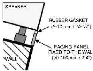
Figure 14. Covering the gap between the wall and the monitor cabinet.
Guarantee
Genelec 1237A and 1238A are supplied with a two year guarantee against manufacturing faults or defects that might alter the performance of the monitors. Refer to supplier for full sales and guarantee terms.
Accessories
A wide selection of accessories is available for Genelec monitors. Consult the Accessories Catalogue on www.genelec.com or your local distributor/dealer for up-to-date information.
necessary to maintain sufficient cooling. Do not obstruct airflow around the monitors.
WARNING!
The Genelec 1237A and 1238A monitors are capable of producing sound pressure levels in excess of 85 dB, which may cause permanent hearing damage.
Maintenance
No user serviceable parts are to be found within the monitor enclosure or the RAM-L amplifier unit. Any maintenance or repair of the monitor should only be undertaken by qualified service personnel.
Compliance to FCC Rules
This device complies with part 15 of the FCC Rules. Operation is subject to the following two conditions:
- This device may not cause harmful interference
- This device must accept any interference received, including interference that may cause undesired operation.
line
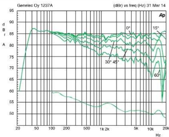
| Frequency (Hz) | dB (dB) at 0° | dB (dB) at 15° | dB (dB) at 30° | dB (dB) at 45° | dB (dB) at 60° | | -------------- | ------------- | -------------- | -------------- | -------------- | -------------- | | 20 | ~85 | ~85 | ~85 | ~85 | ~85 | | 50 | ~85 | ~85 | ~85 | ~85 | ~85 | | 100 | ~85 | ~85 | ~85 | ~85 | ~85 | | 200 | ~85 | ~85 | ~85 | ~85 | ~85 | | 500 | ~85 | ~85 | ~85 | ~85 | ~85 | | 1k | ~85 | ~85 | ~85 | ~85 | ~85 | | 2k | ~85 | ~85 | ~85 | ~85 | ~85 | | 5k | ~85 | ~85 | ~85 | ~85 | ~85 | | 10k | ~85 | ~85 | ~85 | ~85 | ~85 | | 20k | ~85 | ~85 | ~85 | ~85 | ~85 |Figure 15. The upper curve group shows the horizontal directivity characteristics of the 1237A in its vertical configuration measured at 2 m. The lower curve is a 1/6 octave smoothed power response.
line
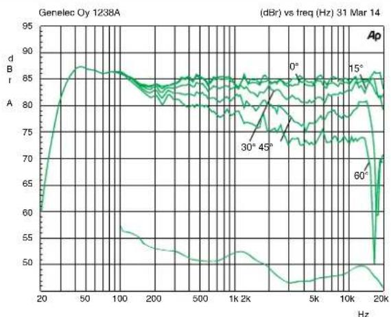
| Frequency (Hz) | dBr (dB) - 0° | dBr (dB) - 15° | dBr (dB) - 30° | dBr (dB) - 45° | dBr (dB) - 60° | | -------------- | ------------- | -------------- | -------------- | -------------- | -------------- | | 20 | ~60 | ~60 | ~60 | ~60 | ~60 | | 50 | ~85 | ~85 | ~85 | ~85 | ~85 | | 100 | ~85 | ~85 | ~85 | ~85 | ~85 | | 200 | ~85 | ~85 | ~85 | ~85 | ~85 | | 500 | ~85 | ~85 | ~85 | ~85 | ~85 | | 1K | ~85 | ~85 | ~85 | ~85 | ~85 | | 2K | ~85 | ~85 | ~85 | ~85 | ~85 | | 5K | ~85 | ~85 | ~85 | ~85 | ~85 | | 10K | ~85 | ~85 | ~85 | ~85 | ~85 | | 20K | ~70 | ~70 | ~70 | ~70 | ~70 |Figure 16. The upper curve group shows the horizontal directivity characteristics of the 1238A in its vertical configuration measured at 2 m. The lower curve is a 1/6 octave smoothed power response.
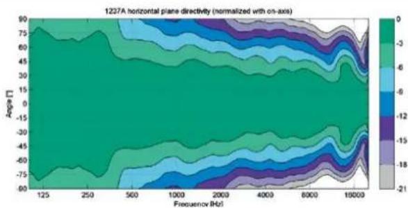
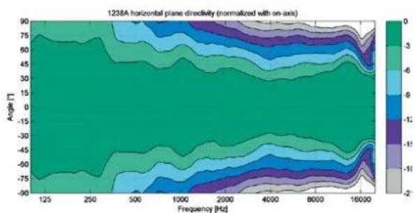
Figure 17. 1237A horizontal directivity plot. Figure 18. 1238A horizontal directivity plot.
heatmap
1238A horizontal plane directly (normalized with on-axis) | Frequency [Hz] | -90° | -75° | -60° | -45° | -30° | -15° | 0° | 15° | 30° | 45° | 60° | 75° | |---|---|---|---|---|---|---|---|---|---|---|---|---| | 125 | -90 | -75 | -60 | -45 | -30 | -15 | 0 | -3 | -6 | -9 | -12 | -2 | | 250 | -75 | -60 | -45 | -30 | -15 | 0 | 30 | 45 | 60 | 75 | 90 | 105 | | 500 | -60 | -45 | -30 | -15 | 0 | 30 | 60 | 75 | 90 | 105 | 120 | 135 | | 1000 | -45 | -30 | -15 | 0 | 30 | 45 | 75 | 90 | 105 | 120 | 135 | 150 | | 2000 | -30 | -15 | 0 | 30 | 45 | 60 | 90 | 105 | 120 | 135 | 150 | 165 | | 4000 | -15 | 0 | 30 | 45 | 60 | 75 | 105 | 120 | 135 | 150 | 165 | 180 | | 8000 | 0 | 30 | 45 | 60 | 75 | 90 | 115 | 135 | 150 | 165 | 180 | 195 | | 16000 | 30 | 45 | 60 | 75 | 90 | 115 | 135 | 150 | 165 | 180 | 195 | 210 | The color scale ranges from -2 (lightest) to +2 (darkest), indicating the direction of the measured variable. The chart displays a single continuous line representing the normalized value of the plane directly for each angle. The x-axis represents frequency in Hertz, and the y-axis represents angle in degrees. The legend is embedded in the plot as a color gradient. The label 'Angle [T]' appears near the top left corner.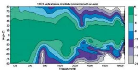
heatmap
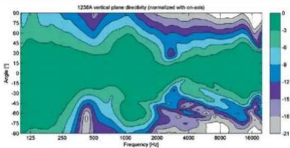
| Frequency [Hz] | Angin [°] | Value | | -------------- | --------- | ----- | | 125 | 90 | 0 | | 250 | 75 | -3 | | 500 | 60 | -6 | | 1000 | 45 | -9 | | 2000 | 30 | -12 | | 4000 | 15 | -15 | | 8000 | 0 | -18 | | 16000 | -15 | -21 |Figure 19. 1237A vertical directivity plot. Figure 20. 1238A vertical directivity plot.
heatmap
1236A vertical plane directivity (normalized with on-axis) | Frequency [Hz] | 125 | 250 | 500 | 1000 | 2000 | 4000 | 8000 | 16000 | |---|---|---|---|---|---|---|---|---| | 90 | -3.5 | -3.5 | -3.5 | -3.5 | -3.5 | -3.5 | -3.5 | -3.5 | | 75 | -4.0 | -4.0 | -4.0 | -4.0 | -4.0 | -4.0 | -4.0 | -4.0 | | 60 | -5.0 | -5.0 | -5.0 | -5.0 | -5.0 | -5.0 | -5.0 | -5.0 | | 45 | -6.0 | -6.0 | -6.0 | -6.0 | -6.0 | -6.0 | -6.0 | -6.0 | | 30 | -7.0 | -7.0 | -7.0 | -7.0 | -7.0 | -7.0 | -7.0 | -7.0 | | 15 | -8.0 | -8.0 | -8.0 | -8.0 | -8.0 | -8.0 | -8.0 | -8.0 | | 0 | -9.0 | -9.0 | -9.0 | -9.0 | -9.0 | -9.0 | -9.0 | -9.0 | | -15 | -8.5 | -8.5 | -8.5 | -8.5 | -8.5 | -8.5 | -8.5 | -8.5 | | -30 | -7.5 | -7.5 | -7.5 | -7.5 | -7.5 | -7.5 | -7.5 | -7.5 | | -45 | -6.5 | -6.5 | -6.5 | -6.5 | -6.5 | -6.5 | -6.5 | -6.5 | | -60 | -5.5 | -5.5 | -5.5 | -5.5 | -5.5 | -5.5 | -5.5 | -5.5 | | -75 | -4.5 | -4.5 | -4.5 | -4.5 | -4.5 | -4.5 | -4.5 | -4.5 | | 125+/-90°, Angle [°] = 90°, Frequency [Hz] = 125, Angle [°] = 90°, Current Density [mV] = 1236A, Current Intensity [W] = 1236A, Current Amplitude [dB] = 1236A, Current Power [W] = 1236A, Current Field [W] = 1236A, Current Amplitude [dB] = 1236A, Current Amplitude [W] = 1236A, Current Amplitude [dB] = 1236A, Current Amplitude [W] = 1236A, Current Amplitude [dB] = 1236A, Current Amplitude [W] = 1236A, Current Amplitude [dB] = 1236A, Current Amplitude [W] = 1236A, Current Amplitude [W] = 1236A, Current Amplitude [dB] = 1236A, Current Amplitude [W] = 1236A, Current Amplitude [dB] = 1236A, Current Amplitude [W] = 1236A, Current Amplitude [dB] = 1236A, Current Amplitude [W] / Current Amplitude [dB] = 1236A, Current Amplitude [dB] = 1236A, Current Amplitude [dB] = 1236A, Current Amplitude [dB] = 1236A, Current Amplitude [dB] = 1236A, Current Amplitude [dB] = 1236A, Current Amplitude [dB] = 1236A, Current Amplitude [dB] = 1236A, Current amplitude [dB] = 1236A, Current amplitude [dB] = 1236A, Current field [dB] = 1236A, Current amplitude [dB] = 1236A, Current field intensity [dB] = 1236A, Current amplitude [dB] = 1236A, Current amplitude [dB] = 1236A, Current amplitude [dB] = 1236A, Current amplitude [dB] = 1236A, Current amplitude [dB] = 1236A, Current amplitude [dB] = 1236A, Current amplitude [dB] = 1236A, Current amplitude [dB] = 1238A, Current amplitude [dB] = 1236A, Current amplitude [dB] = 1236A, Current amplitude [dB] = 1236A, Current amplitude [dB] = 1236A, Current amplitude [dB] = 1236A, Current amplitude [dB] = 1236A, Current amplitude [dB] = 1236A, Current amplitude [dB] =-1236A, Current amplitude [-18B], Current amplitude [-18B], Current amplitude [-18B], Current amplitude [-18B], Current amplitude [-18B], Current amplitude [-18B], Current amplitude [-18B], Current amplitude [-18B], Current amplitude [-18B], Current amplitude [-18B], Current amplitude [-18B], Current amplitude [-18B], Current amplitude [-18B], Current amplitude [-18B], Current amplitude [-18B], Current amplitude [-18B], Current amplitude [-18B], Current amplitude [-18B], Current amplitude [-18B], Current amplitude [-18B], Current amplitude [-18B], Current amplitude [-18B], Current amplitude [-18B], Current amplitude [-18B], Current amplitude [-18B], Current amplitude [-18B], Current amplitude [-18B], Current amplitude [-18B], Current amplitude [-18B], Current amplitude [-21B], Current amplitude [-18B], Current amplitude [-18B], Current amplitude [-18B], Current amplitude [-18B], Current amplitude [-18B], Current amplitude [-18B], Current amplitude [-18B], Current amplitude [-18B], Current amplitude [-18B], Current amplitude [-18B], Current amplitude [-18B], Current amplitude [-18B], Current amplitude [-18B], Current amplitude [-18B].Note: This equipment has been tested and found to comply with the limits for a Class B digital device, pursuant to part 15 of the FCC Rules. These limits are designed to provide reasonable protection against harmful interference in a residential installation. This equipment generates, uses and can radiate radio frequency energy and, if not installed and used in accordance with the instructions, may cause harmful interference to radio communications. However, there is no guarantee that interference will not occur in a particular installation. If this equipment does cause harmful interference to radio or television reception, which can be determined by turning the equipment off and on, the user is encouraged to try to correct the interference by one or more of the following measures:
- Reorient or relocate the receiving antenna.
- Increase the separation between the equipment and receiver.
- Connect the equipment into an outlet on a circuit different from that to which the
receiver is connected.
- Consult the dealer or an experienced radio/TV technician for help.
Modifications not expressly approved by the manufacturer could void the user's authority to operate the equipment under FCC rules.
SYSTEM SPECIFICATIONS
| 1237A 1238A | ||
| Lower cut-off frequency, -3 dB < 35 Hz < 33 Hz | ||
| Upper cut-off frequency, -3 dB > 21 kHz > 21 kHz | ||
| Accuracy of frequency response, ± 2.5 dB | 37 Hz - 20 kHz 35 Hz | - 20 kHz |
| Maximum short term sine wave acoustic output on axis in half space, averaged from 100 Hz to 3 kHz @ 1 m | > 118 dB SPL > 121 | dB SPL |
| Maximum long term RMS acoustic output in the same conditions with IEC weighted noise (limited by driver protection circuit) @ 1 m | > 112 dB SPL > 116 | dB SPL |
| Maximum peak acoustic output per pair in a listening room with music material @ 2 m | > 122 dB > 124 dB | |
| Self generated noise level in free space at 1 m on axis (A-weighted) | < 10 dB < 10 dB | |
| Harmonic distortion at 95 dB SPL at 1 m on axisFreq: 50...200 Hz> 200 Hz | < 3 %< 0.5 % | < 1 %< 0.5 % |
| DriversBassMidrangeTrebleAll drivers are magnetically shielded | 305 mm (12 in)cone125 mm (5 in) cone25 mm (1 in)metal dome | 385 mm (15 in)cone125 mm (5 in) cone25 mm (1 in)metal dome |
| Weight (monitor with integrated amplifier) | 42 kg (93 lb) 57 kg (126 lb) | |
| Weight (monitor with amplifier removed) | 36 kg (80 lb) 51 kg (113 lb) | |
| Amplifier weight 6 kg (13 lb) | ||
| Dimensions (monitor enclosure)HeightWidthDepth | 680 mm (26 34 in)400 mm (15 34 in)380 mm (15 in) | 810 mm (32 in)480 mm (19 in)420 mm (16 12 in) |
| Amplifier dimensions (in rack mount configuration)Height (front panel)Height (amplifier casing)Width (front panel)Width (amplifier casing)Depth | 3U 132 mm (5 36 in)80 mm (3 18 in)483 mm (19 in)425 mm (16 34 in)252 mm (9 116 in) | |
AMPLIFIER SECTION
| 1237A 1238A | ||
| Bass amplifier short term output power | 500 W | |
| Midrange amplifier short term output power | 250 W | |
| Treble amplifier short term output power | 200 W | |
| Long term output power is limited by driver protection circuitry | ||
| Amplifier system THD at nominal output | < 0.01 % | |
| Signal to Noise ratio, referred to full output | ||
| Bass | >115 dB | |
| Midrange | >115 dB | |
| Treble | >115 dB | |
| Mains voltage 100-240 VAC, 50/60 Hz | ||
| Power consumption | ||
| Standby | <0.5 W | |
| Idle | 25 W | |
| Full output | 750 W | |
SIGNAL PROCESSING SECTION
| 1237A 1238A | ||
| Analog signal input connectorXLR female, balanced 10 kOhm | pin 1 gndpin 2 non-inverting,pin 3 inverting | |
| Maximum analog input signalAnalog input sensitivity(100 dB SPL at 1 m)Analog input gain selection | +25.0 dBu-6 dBu0,+6,+12,+18 dB | |
| Digital signal input connectorXLR female 110 Ohm | AES/EBU Single Wire or Dual Wire | |
| Digital signal output / Thruconnector XLR male 110 OhmDigital audio inputWord lengthSample rateDigital input sensitivity(100 dB SPL at 1 m )Digital input gain selection | AES/EBU Single Wire or Dual Wire16 - 24 bits32 - 192 kHz-30 dBFS0,+6,+12,+18 dB | |
| Control networkTypeConnection | Proprietary GLMTMnetwork2 RJ45, CAT5 cables | |
| Crossover frequencyBass/MidMid/Treble | 450 Hz3.0 kHz | 420 Hz3.0 kHz |
| GLMTMsoftware frequencyresponse adjustmentNotch filtersShelving filters | 4 LF and 2 HF2 LF and 2 HF | |
| System calibration | Genelec GLM AutoCalTM | |
Genelec Document D0114R001b Copyright Genelec Oy 7.2021. All data subject to change without prior notice
www.genelec.com
Genelec 1237A and 1238A 操作手册
数字环DHG(TAL THRU AES/EBU)
数字输 DIGITAL IN AES/EBU
natural_image
Technical line drawing of a rectangular enclosure with internal components, no text or symbols presentnatural_image
Isometric line drawing of a rectangular electronic device with internal grid structure (no text or symbols)图 9. 安装 L 型挂耳支架。
natural_image
Technical line drawing of an electronic device casing with mounting flanges and a grid-patterned panel (no text or symbols)图 10. 安装功放前面板。
natural_image
Technical line drawing of a mechanical or electrical component with no visible text, numbers, or symbols.natural_image
Technical illustration of an electrical enclosure with ventilation grilles and mounting brackets (no text or symbols)图 8. 拆下功放前部的挂耳支架。
安全注意事项
heatmap
1237A horizontal plane directly (normalized with on-axis) | Frequency (Hz) | 125 | 250 | 560 | 1000 | 2000 | 4000 | 8000 | 18000 | |---|---|---|---|---|---|---|---|---| | 90 | -3.5 | -3.5 | -3.5 | -3.5 | -3.5 | -3.5 | -3.5 | -3.5 | | 75 | -3.5 | -3.5 | -3.5 | -3.5 | -3.5 | -3.5 | -3.5 | -3.5 | | 60 | -3.5 | -3.5 | -3.5 | -3.5 | -3.5 | -3.5 | -3.5 | -3.5 | | 45 | -3.5 | -3.5 | -3.5 | -3.5 | -3.5 | -3.5 | -3.5 | -3.5 | | 30 | -3.5 | -3.5 | -3.5 | -3.5 | -3.5 | -3.5 | -3.5 | -3.5 | | 15 | -3.5 | -3.5 | -3.5 | -3.5 | -3.5 | -3.5 | -3.5 | -3.5 | | 0 | -3.5 | -3.5 | -3.5 | -3.5 | -3.5 | -3.5 | -3.5 | -3.5 | | -15 | -3.5 | -3.5 | -3.5 | -3.5 | -3.5 | -3.5 | -3.5 | -3.5 | | -30 | -3.5 | -3.5 | -3.5 | -3.5 | -3.5 | -3.5 | -3.5 | -3.5 | | -45 | -3.5 | -3.5 | -3.5 | -3.5 | -3.5 | -3.5 | -3.5 | -3.5 | | -60 | -3.5 | -3.5 | -3.5 | -3.5 | -3.5 | -3.5 | -3.5 | -3.5 | | -75 | -3.5 | -3.5 | -3.5 | -3.5 | -3.5 | -3.5 | -3.5 | -3.5 | | 0 | 0 | 0 | 0 | 0 | 0 | 0 | 0 | 0 | | 125 | 0 | 0 | 0 | 0 | 0 | 0 | 0 | 0 | The chart displays a contour plot of the normalized values for the horizontal plane directly, with the x-axis representing frequency in Hz and the y-axis representing angle in degrees (degrees). The color scale indicates the value magnitude, ranging from approximately 0 to 21, with darker shades corresponding to lower values and lighter shades to higher values.- Genelec 1237A and 1238A Operating Manual
- Introduction
- System
- Drivers and Cabinet Construction
- Amplifiers and Signal Processing
- Mounting Considerations
- Minimum Clearances
- Set-up and Use
- Monitor calibration and setup
- Recommendations for AES/EBU Audio
- "DIGITAL THRU AES/EBU" Connector
- "ANALOG IN" Connector
- "CONTROL NETWORK" Connectors
- "Loudspeaker Connectors" Group
- "LED" Connector
- RAM-L Amplifier Power Button
- Setting ISS™
- Connections
- "MAINS INPUT" Connector
- "DIGITAL IN AES/EBU" Connector
- Front Panel Light Functions
- Mounting RAM-L Amplifier in a 19 Inch Rack
- Flush Mounting the Monitor Enclosure
- Testing Mode
- Safety Considerations
- Guarantee
- Accessories
- WARNING!
- Maintenance
- Compliance to FCC Rules
- 数字环DHG(TAL THRU AES/EBU)
- 安全注意事项
Brand : GENELEC
Model : 1238A
Category : Monitor