
4430A - Monitor GENELEC - Free user manual and instructions
Find the device manual for free 4430A GENELEC in PDF.


| Product Type | Active Studio Monitor |
| Model | 4430A |
| Brand | Genelec |
| Speaker Configuration | 2-way |
| Woofer Size | 6.5 inches |
| Tweeter Size | 1 inch dome |
| Amplifier Power (Low Frequency) | 120 W Class D |
| Amplifier Power (High Frequency) | 90 W Class D |
| Frequency Response | 48 Hz - 20 kHz (±3 dB) |
| Maximum SPL | 110 dB (peak) |
| Input Connectors | XLR (balanced), RCA (unbalanced) |
| Dimensions (Height x Width x Depth) | 350 x 250 x 300 mm (13.8 x 9.8 x 11.8 in) |
| Weight | 15 kg (33 lb) |
| Power Consumption | 60 W (idle), 150 W (max) |
| Primary Functions | Accurate sound reproduction with room response controls |
| Room Response Controls | Bass tilt, treble tilt, bass roll-off, desktop placement |
| Cleaning and Maintenance | Wipe with a soft, dry cloth; avoid liquids and abrasives |
| Safety Precautions | Do not expose to water or humidity; disconnect power when not in use |
| Spare Parts and Reparability | Contact authorized Genelec service centers for repairs |
| General Information | Professional monitoring for studios and critical listening |
Frequently Asked Questions - 4430A GENELEC
User questions about 4430A GENELEC
0 question about this device. Answer the ones you know or ask your own.
Ask a new question about this device
Download the instructions for your Monitor in PDF format for free! Find your manual 4430A - GENELEC and take your electronic device back in hand. On this page are published all the documents necessary for the use of your device. 4430A by GENELEC.
USER MANUAL 4430A GENELEC
natural_image
Interior of a modern, minimalist interior with lush green tree branches and hanging pendant lights under wooden ceiling (no text or symbols visible)GENELEC®
Table of Contents
1 Introduction....4
2 Glossary 5
3 System Components....6
3.1 Selecting IP switch devices....6
3.1.1 Capacity / bandwidth 6
3.1.2 PoE support....7
3.1.3 PoE budget calculation 8
3.1.4 Network Structure....8
4 Getting Started....10
4.1 System Control and Zone Plan 10
4.2 Positioning and mounting the loudspeakers....12
4.3 Connection Analog Input....13
4.4 Connecting Ethernet and PoE to loudspeakers....14
4.5 Downloading and Installing Smart IP Manager....15
4.6 Downloading and Installing Smart IP Controller 15
4.7 Setting Up IP Audio Stream 15
5 Using Smart IP Manager....17
5.1 Menus....18
5.2 Audio network settings....19
5.3 Zones 20
5.3.1 Default Zone 20
5.3.2 Creating Zones 21
5.3.3 Assigning Loudspeakers to the Zone 24
5.4 Loudspeaker management 26
5.5 Loudspeaker Information and Settings....27
5.5.1 Input tab 28
5.5.2 Acoustic tab 29
5.5.2.1 Delay 30
5.5.2.2 Sensitivity 30
5.5.2.3 Filters....30
5.5.2.4 Filter Frequency Response Graph 31
5.5.2.5 Storing Acoustic Settings to Profile Preset....32
5.5.3 Info tab 33
5.5.3.1 Identify the loudspeaker....33
5.5.3.2 Booting the loudspeaker 34
The loudspeaker can be booted by clicking the 'Boot' button. The Smart IP loudspeaker turns OFF and will drop from the network until it has booted. 34
5.5.3.3 Put the loudspeaker to standby....34
5.5.3.4 Update the Firmware of the Loudspeaker....34
5.5.3.5 Loudspeaker information 35
5.5.3.6 ISS Settings.... 35
5.5.3.7 LED Intensity 36
5.5.4 Events tab....36
5.5.5 Network tab 36
5.5.5.1 Zone Credentials 37
5.5.5.2 Access to Unauthorized Loudspeakers....38
6 How to configure and use the Smart IP Controller App 40
6.1 WiFi Setup for the Smart IP Controller App....40
6.2 Enabling Smart IP Controller App on your WLAN 41
6.3 Configuring Smart IP Controller App 42
6.4 Daily Use of Smart IP Controller App 45
7 Frequently Asked Questions....47
7.1 Where can I find more information about Dante? 47
7.2 Why can't I select an audio stream in the Dante Controller matrix?......47
7.3 Why can't I edit/control loudspeakers that are listed with Smart IP Manager?......47
7.4 Why a Smart IP loudspeaker won't power up? 47
7.5 Does Smart IP loudspeaker support AES67 streams? 47
7.6 Is there Smart IP subwoofers available? 47
7.7 How can I reset the Smart IP loudspeaker to the factory state? 47
1 Introduction
Genelec Smart IP system for installed audio applications can be configured by Smart IP Manager software. This software is specifically designed to be used by installers during system set-up, and allows the configuration of almost unlimited numbers of rooms, zones, loudspeakers and audio channels. For daily system management a public API command set allows Smart IP loudspeakers to be integrated into house automation systems – enabling end user control of simple parameters including volume, power on/off, loudspeaker activity and a selection of pre-programmed audio settings.
To help cope with challenging acoustic environments, Smart IP Manager integrates with the loudspeaker's internal DSP to allow analysis and corrective equalisation of any detrimental room acoustics, along with control of delay and level alignment. Internal memory within the speaker then allows instant recall of settings, allowing fast and accurate deployment in any environment.
Take a moment to familiarize yourself with the contents of this manual. In this manual we give suggestions for various types of installations and application scenarios.
We are also ready to help you at any time. For support, first contact your local dealer. Genelec sales network is well trained to help and support you. You can also contact Genelec directly at support@genelec.com
2 Glossary
| Abbreviation or term Explanation | |
| 44xx (xx is two numbers) Family of Smart IP Loudspeakers. | |
| AES67 AES67 is a technical standard for audio over IP and audio over Ethernet interoperability. | |
| Dante Dante audio is a proprietary audio over IP networking method, providing digital audio distribution over IP networks (www.audinate.com). | |
| DHCP Dynamic Host Configuration Protocol; used to automatically assigning IP addresses and other communication parameters to devices connected to the network. | |
| IGMP Internet Group Management Protocol; a communications protocol used by hosts and adjacent routers on networks to establish multicast group memberships. IGMP is an integral part of IP multicast and allows the network to direct multicast transmissions only to hosts that have requested them. | |
| IP Internet Protocol | |
| PoE Power-over-Ethernet | |
| QoS Quality of service (QoS) is the use of technologies that work on a network to control traffic and ensure the performance of critical applications with limited network capacity. | |
| VLAN Virtual LAN: any broadcast domain that is partitioned and isolated in a computer network at the data link layer. | |
| Zone Zone is a collection of loudspeakers working together. | |
3 System Components
Genelec Smart IP system for installed audio applications consists of the following components from Genelec:
- PoE powered Genelec Smart IP loudspeakers
- Genelec Smart IP Manager software for configuring loudspeakers for network settings, acoustic calibrations, and selecting Audio over IP stream input or analogue balanced line input. Available for Windows (www.genelec.com/smart-ip-manager)
The Genelec Smart IP loudspeakers support multichannel Dante audio streams and maximum eight-channel AES67 audio streams.
Other components you need are
- Standard Ethernet IP switch devices with a PoE+ (802.3at) outputs for the Smart IP loudspeakers, or an IP switch with no PoE support and a PoE+ power injector; we recommend managed IP switch devices that support IGMP and QoS (these IP protocols are usually advertised in the IP switch documentation when the switch supports them)
- Dante Controller software by Audinate, for configuring audio streams in Dante format or AES67 format
- an audio-over-IP stream source transmitting AES67 or Dante audio
- Standard CAT cabling (CAT5e minimum or CAT 6 or higher; STP cable is recommended)
Optional components:
- Wireless router (optional if want to use wireless connection for communication) – Make sure that IGMP snooping is enabled in the wireless router to avoid AoIP streams to be flooded to the Wireless communication as it will prevent control messages and other traffic over WiFi
- Genelec Smart IP Controller app to control the Smart IP system after the network setup and configuration using the Smart IP Manager. The Genelec Smart IP Controller app is available for iOS and Android devices through the official application stores
- When you manage Genelec Smart IP loudspeakers using a house automation system, you can obtain documentation of the Smart IP API interface from Genelec, or you may be able to use a home automation system driver for Smart IP loudspeakers. The API drivers are available for several home automations systems at the Genelec web site.
3.1 Selecting IP switch devices
Genelec Smart IP loudspeakers support Audinate Dante technology. The loudspeaker has two IP addresses, one for receiving the audio-over-IP stream and one for management and monitoring of the loudspeaker.
3.1.1 Capacity / bandwidth
Bandwidth requirements for the IP switch device depend on your network size and usage.
Gigabit switches are highly recommended. The use of 100 Mbps or lower IP switches is discouraged as the small capacity will adversely effect the system performance.
We also recommend building a dedicated network (physical or VLAN) intended only for media (audio and video) instead of using the same network for all traffic.
If there is also significant other traffic besides the media traffic on the network, we recommend that Quality of Service support in the IP switches should be available and should be configured in use.
When multicast audio or video streams are present on the network, we recommend that switches are configured to use the IGMP for managing load of the multicast traffic. Devices that have only 100 Mbps network interfaces can become overloaded in high channel count applications if this is not done.
Further details regarding the selection and setup of IP switches can be found for example in https://www.audinate.com/networks-and-switches. All IP switches do not support the PoE functionality needed by Smart IP loudspeakers and therefore can only be used with Smart IP System when separate PoE power injectors are used.
3.1.2 PoE support
Smart IP loudspeakers receive power on the same cable with IP traffic. This technology is called Power over Ethernet. Genelec Smart IP supports standard PoE (13 W power into the device) and PoE+ (about 24 W into the device) power levels. An IP switch must support the IEEE 802.3at standard to have the capability for PoE+.
A 15W or 30W of power budget for each Genelec loudspeaker is needed. This may have to be manually configured into a PoE-capable IP switch. Genelec Smart IP loudspeakers also supports automatic arbitration of the power budget with the capable IP switches.
Each IP switch manufacturer gives instructions on
• how to turn on/off PoE in certain powers
• how to manage PoE capacity in the IP switch
• how to monitor the power consumption for each port
Consult the IP switch operating manual for these details. These help you ensure and understand that the PoE supply has been configure correctly.
The loudspeaker communicates with the PoE capable IP switch automatically to set the PoE power on and to the correct capacity. This is the basic PoE activation mechanism. This may result in only 15 W being available for the loudspeaker. Certain IP switches require also the use of LLPD protocol to obtain the full 30W power out from the IP switch.
When IP switch uses LLDP negotiation between the switch and the loudspeaker it should work entirely automatically. If you experience problems in enabling the PoE power, it may be necessary to edit the LLDP settings or even entirely turn off the LLDP negotiation.
3.1.3 PoE budget calculation
The Smart IP Loudspeaker supports automatic negotiation with the IP switch or IP power injector to set the PoE power level. However, in some cases it may be necessary to set the PoE power level in the switch manually.
Table 1. PoE and PoE+ power levels.
| Name Standard Power at switch Min. power at 44xx | |||
| PoE IEEE | 802.3af-2003 15.4 W 12.95 W | ||
| PoE+ IEEE | 802.3at-2009 30 W 25.5 W | ||
There are several Power-over-Ethernet standards. The Smart IP Loudspeaker supports the PoE+ standard but also works with the lower power PoE standard. When the Smart IP Loudspeaker also works with lower PoE power, the duration of high SPL output is shortened, and long continuous output signals play at lower sound level than when the PoE+ power level is used. Genelec recommends using PoE+ power level with Smart IP Loudspeaker.
Each PoE supply device (IP switch or power injector) has a certain maximum output power capacity. This can limit the number of PoE outputs that can be set on. For Smart IP Loudspeaker, calculate the output power for each output as 15.4 W for PoE and 30 W for PoE+. Ensure that the total power does not exceed the switch or power injector total power.
Example: IP switch total power is 150 W. You use PoE+ and four outputs are connected. The total output power is 4 x 30 W = 120 W. This is smaller than the capacity of the Ip switch, 150 W. This scenario is acceptable.
3.1.4 Network Structure
Genelec recommends always designing a network structure with star topology. Only one IP device (for example, one 4430A) should be connected at one port in an IP switch. IP device ports should not be daisy chained to several IP devices.
Audio-over-IP requires the use of cable-based LAN network. Low-latency uncompressed audio-over-IP streaming does not work over WLAN.
In bigger networks with data, audio and video traffic it might be usable to configure separate VLANs (Virtual LAN) for each usage or separate networks physically to ensure the best performance for each network.
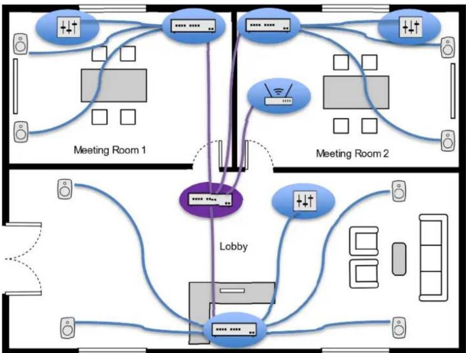
In Figure 1 there is a separate audio network created with one PoE switch in the Meeting Room 2. It will handle all Audio over IP traffic and control and has no connection to the office network (Data Switch). This example is the easiest network implementation.
PoE switches in the Meeting Room1 and the Lobby are connected to the office network. These two PoE switches use VLANs to separate office data and audio networks. This method requires more advanced network knowledge and needs some configuration of the switches.
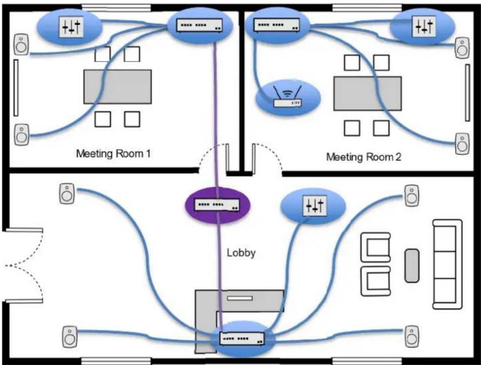
Figure 1. Network cabling example.
4 Getting Started
To take full advantage of your Smart IP system it is important to become familiar with all the system components.
To set up a system you will need Smart IP monitors, audio signal cables, ethernet network cables, Smart IP Manager software and other components listed in the previous chapter.
To set up a Genelec Smart IP system,
- Plan system control and zones
- Place Smart IP loudspeakers in the room
- Run ethernet network cables from the Ethernet switch to all Smart IP loudspeakers
- Run audio cables to the Smart IP loudspeakers (optional)
- Download and install the Smart IP Manager software, https://www.genelec.com/smart-ip-manager
- Download and install the Dante Controller software, https://www.audinate.com/products/software/dante-controller
- Setup IP Audio stream Dante Controller software
- Configure the system using the Smart IP manager.
4.1 System Control and Zone Plan
The system configuration depends how access to the devices want to be limited. The simplest way is to use a single zone where all devices belong to the one control zone. By default all Smart IP loudspeaker belong to “Default” zone. This means that if controlling e.g. Default zone volume then all loudspeakers will follow that volume. This plan is also suitable if the system volume can be individually controlled from the audio source and Smart IP controlling method not needed.
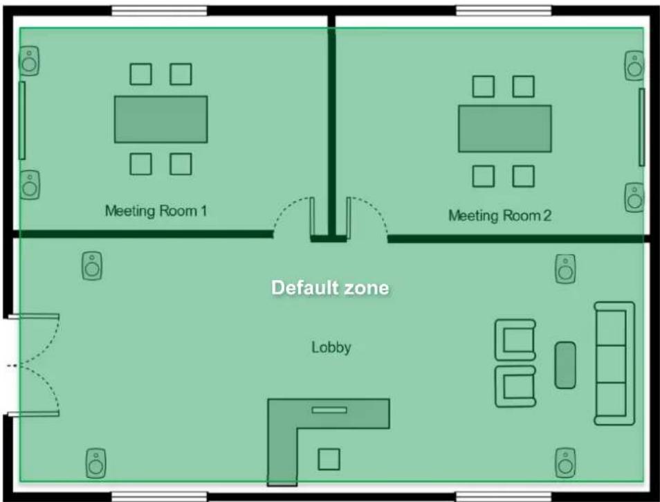
Figure 2. The default zone.
In the example the one zone option it's not suitable if there is need to control each room separately with the Smart IP controller or API. Separate control can be easily done by dividing each room to own controlling zone.
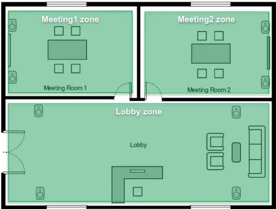
Figure 3. Own zone for each room.
It's good practice to document where each Smart IP Loudspeakers are installed.
Table 1. System identifier documentation example.
| Serial number Genelec MAC Dante MAC | IP Address Receiver | name | Location | |
| 4430AM180 AC:47:23:20:01:3A 00:1D:C1:82:22:31 DHCP Genelec- | 822231 | Meeting Room1 | ||
| : : : : : | : | |||
| 4430AM192 | AC:47:23:20:00:10 | 00:1D:C1:82:22:41 | 192.168.1.23 | Genelec-822241 |
With this information it's possible to track where each loudspeaker is located later without using LED blinking and being in the same room. Receiver name is the most usable to make a loudspeaker easier to identify later. The receiver name can be changed from Dante Controller.
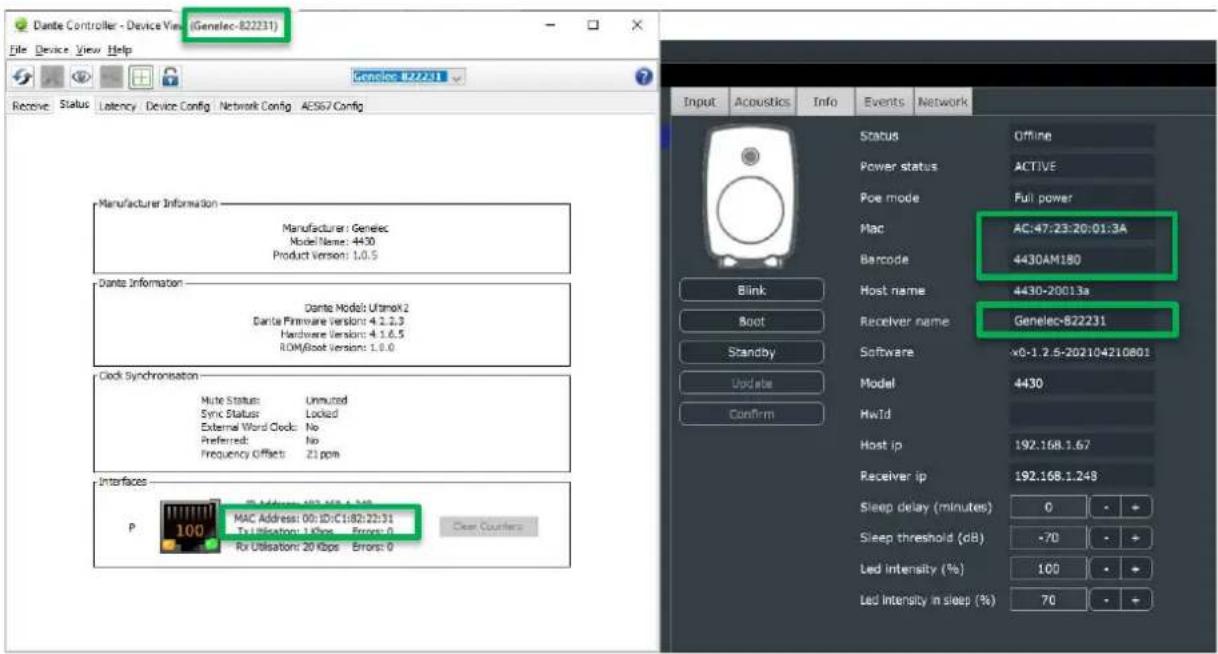
Figure 4. Indentifiers.
4.2 Positioning and mounting the loudspeakers
Place the loudspeaker so that the line of the acoustic axis points towards the main listening area. The AV install designers may indicate different aiming.
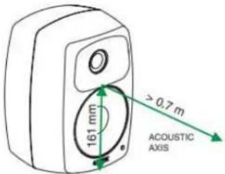
Figure 5. Definition of the acoustic axis.
Several mounting options are available for each loudspeaker model. See Genelec Accessories Catalogue on www.genelec.com for a complete list of mounting hardware options. The accessories can come with instructions on the proper methods of installation.
4.3 Connection Analog Input
Before cabling, turn off the power in all loudspeakers.
An analogue audio input is provided using a screw-mount Euroblock connector. This enables easy connectivity and daisy-chaining the balanced audio signal to several loudspeakers. When you daisy-chain loudspeakers, connect a second signal cable to the plug (Figure 6).
The input impedance of the analogue input is 10 kOhm. The pin sequence of the connector is shown in Figure 6. The number of loudspeakers that can be on the same daisy chain is set by the capability of the source device analogue output. The daisy-chained loudspeakers appear electrically in parallel, reducing the load impedance presented to the source device. Typically, 10 to 20 loudspeakers can be daisy-chained on one balanced line.
If there is a need to connect the analogue input of the speaker to the same circuit as a passive loudspeaker system, please connect the Smart IP loudspeakers analogue input in parallel with the amplifiers analogue input.
Avoid connecting Smart IP loudspeakers to the power amplifier outputs. If this must be done, use a balanced attenuator. Typically, an attenuation of about 20 dB is needed. Beware that some power amplifiers can provide a signal that exceeds the maximum voltage at the analogue input, and this can result in failure of the analogue input.

Figure 6. Balanced analogue input pin-out (left) and daisy-chaining cables in the analogue input Euroblock connector (right).
4.4 Connecting Ethernet and PoE to loudspeakers
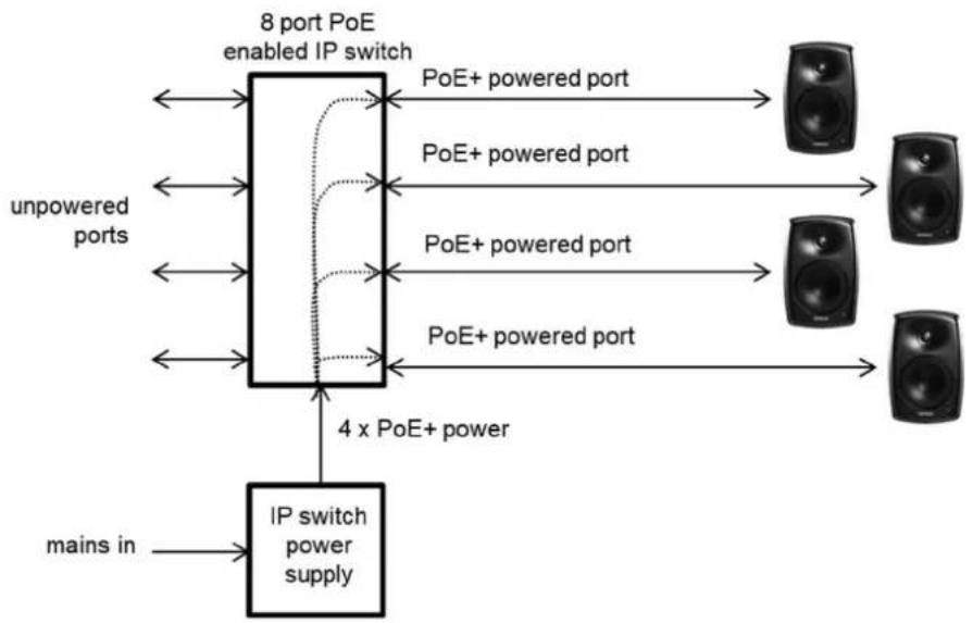
Example of powering the Smart IP loudspeaker with a PoE+ enabled IP switch. With this method, the power budget available for all outputs connected to the IP switch must enable each Smart IP loudspeaker to run at full PoE+ power. For 4 loudspeakers, the power supply must support 4 x PoE+ power level.
Connect an Ethernet cable from the PoE+ output in an IP switch to the Smart IP loudspeaker Ethernet port. Use at least CAT5 cable or better. Press the power switch to power up the loudspeaker.
flowchart
graph TD
    A["8 port PoE enabled IP switch"] -->|PoE+ powered port| B["Speaker 1"]
    A -->|PoE+ powered port| C["Speaker 2"]
    A -->|PoE+ powered port| D["Speaker 3"]
    A -->|PoE+ powered port| E["Speaker 4"]
    F["mains in"] --> G["IP switch power supply"]
    G --> H["4 x PoE+ power"]
    H --> A
    style A fill:#f9f,stroke:#333
    style B fill:#ccf,stroke:#333
    style C fill:#ccf,stroke:#333
    style D fill:#ccf,stroke:#333
    style E fill:#ccf,stroke:#333
    style F fill:#fff,stroke:#333
Figure 7. Smart IP loudspeakers powered with PoE+ IP switch.
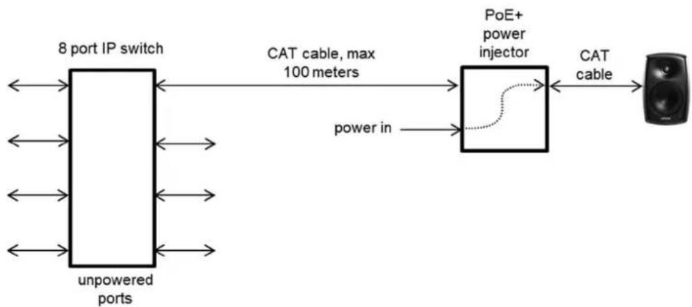
Example of powering the Smart IP loudspeaker with a PoE+ power injector. This method enables the use of standard non-PoE IP switches. Each power injector must support full PoE+ power level into the device.
flowchart
graph LR
    A["8 port IP switch"] -->|CAT cable, max 100 meters| B["PoE+ power injector"]
    B -->|power in| A
    B --> C["Speaker"]
    A <--> D["unpowered ports"]
    D <--> A
Figure 8. Smart IP loudspeaker powered by an IP PoE+ power injector.
4.5 Downloading and Installing Smart IP Manager
Acoustic calibration, zone setup, input selection and loudspeaker management are done using Genelec Smart IP Manager software. This is a software intended for AV installers. Genelec recommends using the Application Programming Interface (API) inside the loudspeaker to be used with home automation systems for the end-user control.
Download Smart IP Manager at https://www.genelec.com/smart-ip-manager and follow screen instructions to install.
4.6 Downloading and Installing Smart IP Controller
Optional Smart IP Controller App can be downloaded for Smart IP system control. Applications are available in Google Play store and Apple Store. To be able to use the controller the network should be extended with a Wifi router.
4.7 Setting Up IP Audio Stream
Audio stream setup is done by using Dante Controller software. Download the software from https://www.audinate.com/products/software/dante-controller
Each Smart IP Monitor can be configured to receive one or two audio channels.
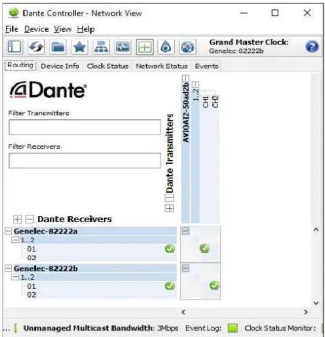
Figure 9. Configuring streams in the Dante controller.
The Smart IP loudspeaker can receive two independent input streams. The output audio is a 1:1 mix of the two streams. This can support use cases where different streams are set up for different applications, for example one stream for the background music and one stream for live audio or announcements. Then, the user can control which stream is playing at the audio source side. The sample rate and audio format for the two streams must be the same.
It is also possible to mix Dante format and AES67 format audio streams with this method.
An AES67 audio stream supported by the loudspeaker can have contain the maximum of 8 audio channels. Dante automatically divides a multichannel stream into several low channel count flows suitable for the speaker and this process is automatic.
The AES67 compatibility mode must turn on ON to enable reception of AES67 streams. Follow these instructions on Dante Controller:
- Double click on the loudspeaker to be configured. The Device View window opens.
- Click AES67 Config -tab.
• In the AES67 Mode panel, go to New: and select Enabled. - In the Reset Device panel, click Reboot to reboot loudspeaker with AES67 enabled.
The audio reproduction can also be controlled from the loudspeaker settings, e.g., it's possible to switch between analog and audio over IP inputs, please check Input tab chapter about the input settings.
5 Using Smart IP Manager
When starting Smart IP Manager for the first time the network interface which is used for controlling the Smart IP loudspeakers need to be defined. For example, most computers offer a cable-based IP network and WLAN interfaces.
IP addresses can be set following ways:
• DHCP (recommended)
- Manual IP address
- AutoIP (not recommended – used automatically if nothing else not available 169.254.x.x)
- IP address mask
Select the network in the menu item 'Settings' | 'Audio network'. The IP network is selected by giving the IP network address of the computer IP network interface you want to use. Please use the 'ipconfig' command to get a list of all IP networks in their IP addresses in the computer. Enter the IP address of the interface you want to use.
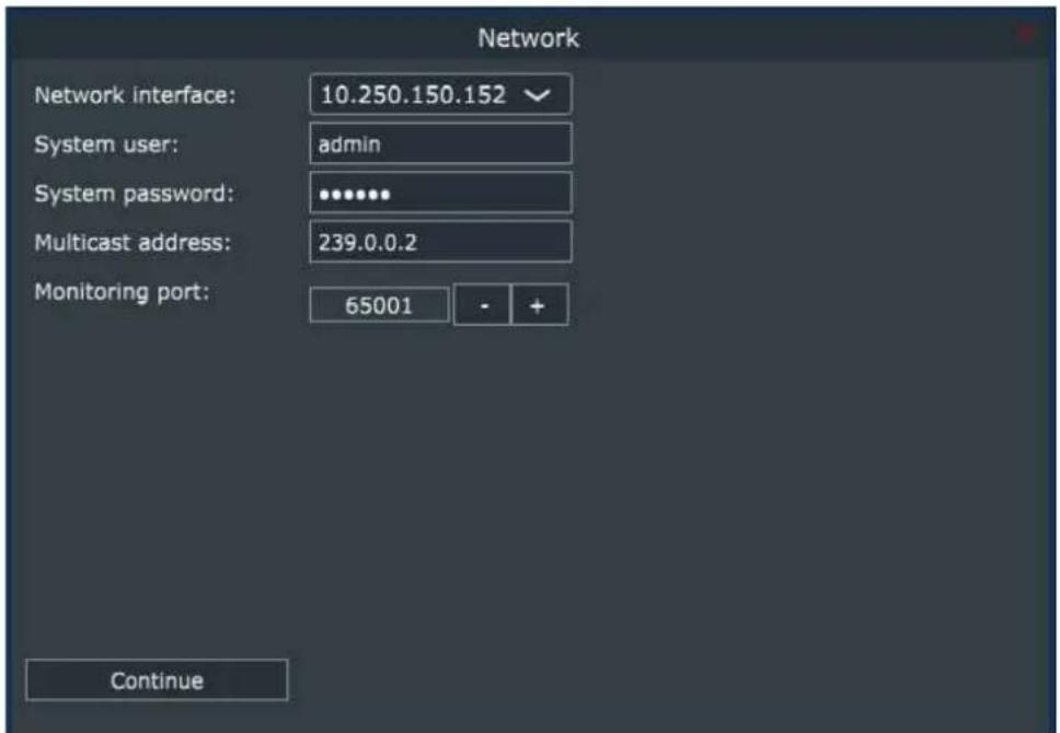
Figure 10. Audio network settings window.
To start using the Smart IP manager with a certain loudspeaker you need the System username and System password. When the loudspeaker leaves the factory, the loudspeaker has been assigned default credentials that are System username 'admin' and System password 'admin'. Always change these when you access the loudspeaker the first time (see Zone Credentials chapter).
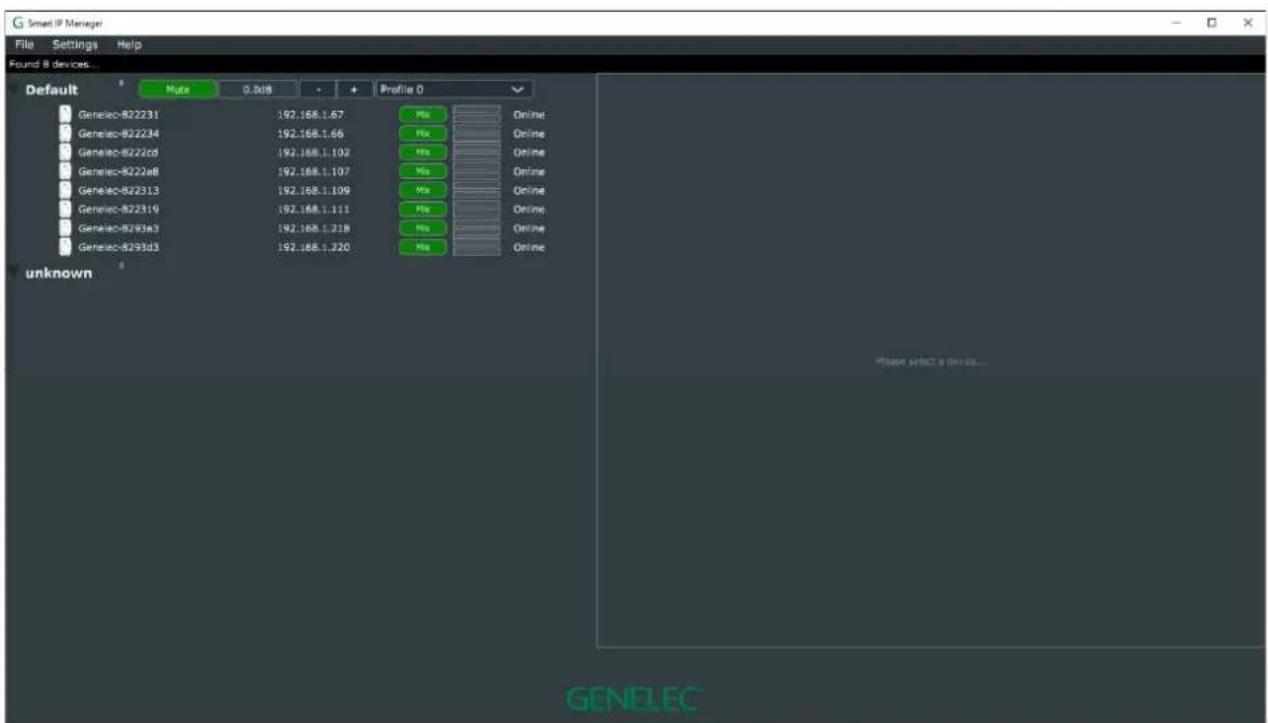
Figure 11. Smart IP Manager with the default zone.
5.1 Menus
The main menu contains a set of menu command enabling system management.
File menu
'Add zone' creates a new zone.
'Clear all messages' clears all status message logged by Smart IP Manager.
'Query devices' forces the Smart IP device query message to be send.
'Check for updates' forces the software update check.
'Clear three' will clear zone three to remove old zones. Query devices after clearing.
'Exit' closes the Smart IP Manager application.
Settings menu
'Audio network' opens network settings page for the computer.
Help menu
'About' show information about Smart IP Manager, including the software version information.
'Online manual' opens online manual for Smart IP Manager.
5.2 Audio network settings
The audio network settings define settings used to communicate with the Smart IP loudspeakers.
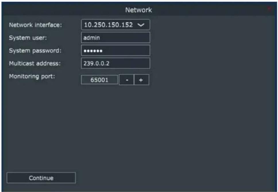
Figure 12. Audio network settings page.
• Network interface: Select an IP address that is used for the audio network.
- System user: Set a username that is used for Smart IP communication (default: admin).
- System password: Set a password that is used for Smart IP communication (default: admin).
- Multicast address: Multicast address used in the Smart IP system is shown in this field. Not used.
- Monitoring port: The default port is set in this field. Normally there is no need to edit this port number. If you know that this port number is not available, you can use another vacant port. In that case, enter a vacant port number and restart the Smart IP Manager to update the port number.
5.3 Zones
Zones are collections of loudspeakers working together, for example within an audio reproduction area. By default, all loudspeakers belong to the Default zone. Using the Default zone can be very handy as this enables quick and easy setup of a system that reproduces only a limited number of audio channels and can be easily controlled as one system. Examples of these kind of systems could be background music of an office or a restaurant. Very little configuration is needed when the default zone is used.
5.3.1 Default Zone
In the Figure 13 there is 8 Smart IP loudspeakers with the default settings.
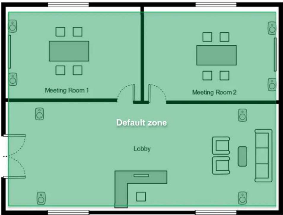
Figure 13. The default zone.
All eight Smart IP loudspeakers are listed under the Default zone in Smart IP Manager. Muting or changing the volume of the Default zone will affect all the Smart IP loudspeakers in the zone.
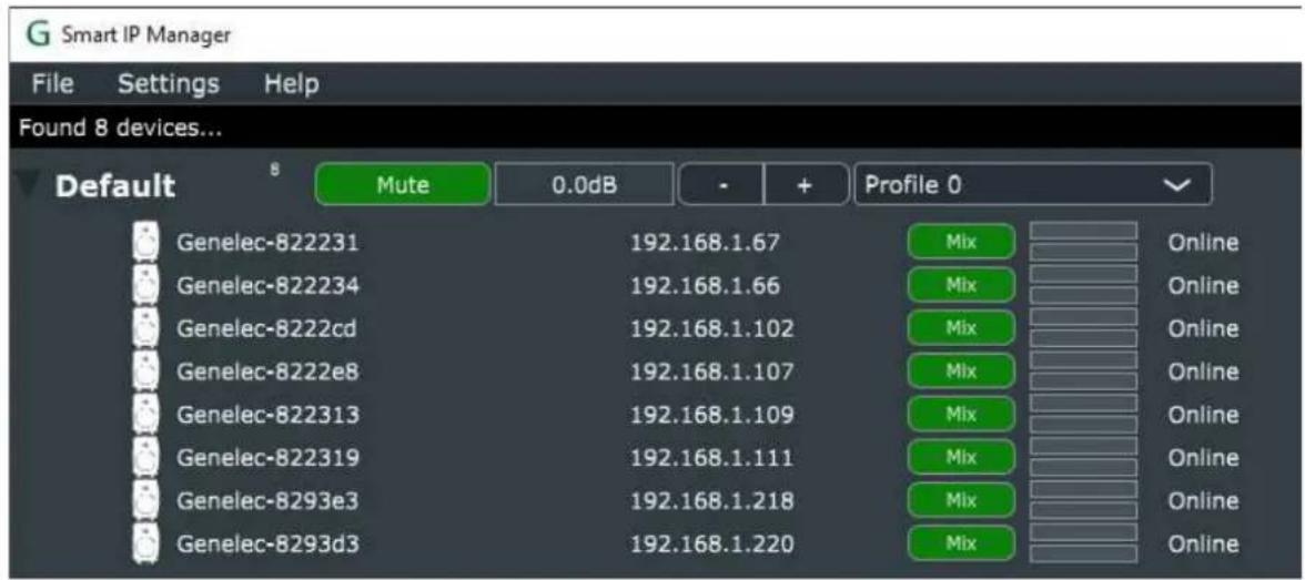
Figure 14. Default zone listing.
5.3.2 Creating Zones
To control rooms/zones separately and individually, the Smart IP playback system can be divided into several zones. In the zone plan below we have three example zones, named Meeting1, Meeting2 and Lobby.
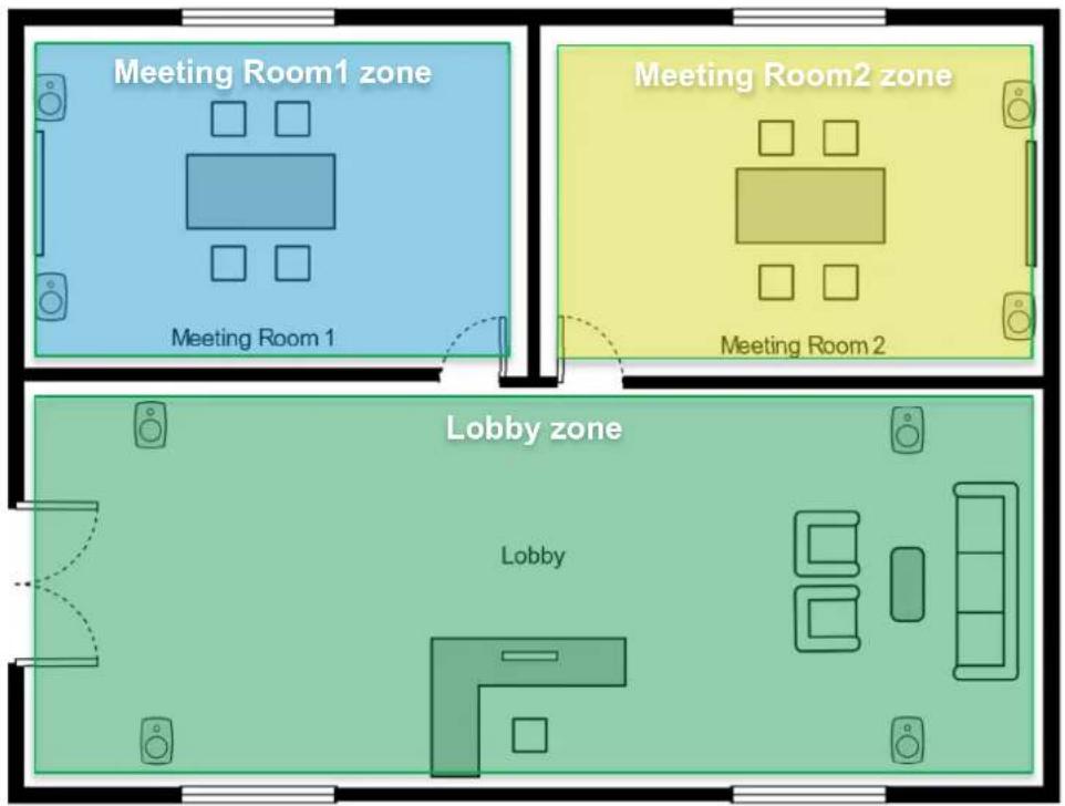
Figure 15. Three Zone example.
- To create a zone, click 'File : Add zone' menu item in the Smart IP Manager. The Create zone window opens.
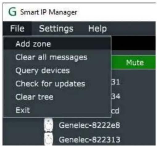
Figure 16. Add a new zone.
- Give name "Meeting1" for the zone. Id(port) is automatically created by Smart IP Manager. If the port number is reserved or blocked for any reason, the port number used can be changed. Click the 'Create' button to create a zone. Note: If loudspeakers are not assigned to a zone and Smart IP Manager closed the zone and the zone will disappear from the Smart IP Manager window.
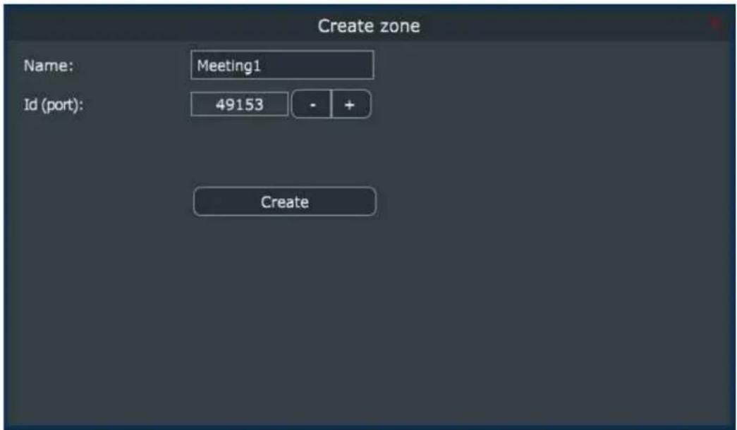
Figure 17. Create 'Meeting1' zone.
- Repeat steps 1-2 for until all needed zones created.
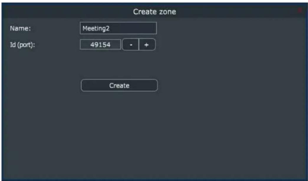
Figure 18. Create 'Meeting2' zone.
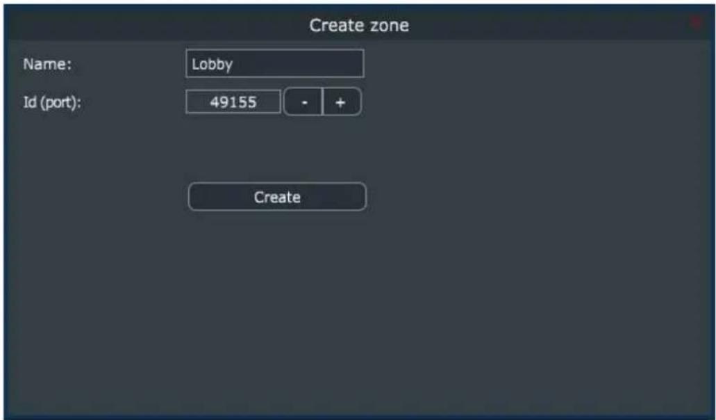
Figure 19. Create 'Lobby' zone.
5.3.3 Assigning Loudspeakers to the Zone
After the required zones have been created, the loudspeakers need be assigned to the zones. The instructions below show how to find the loudspeakers in the Meeting Room 1 and assign those to the zone.
- Finding the correct loudspeaker and adding it to a zone. A loudspeaker can be identified by selecting it from the list and clicking the Blink button in the Info tab -> the selected loudspeaker will flash the LED.
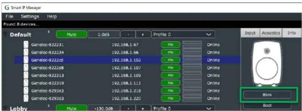
Figure 20. Identify a loudspeaker from Smart IP Manager.
- To assign the loudspeaker to the zone, open the 'Network' tab and select the correct zone name (in out example, 'Meeting1') in the Zone dropdown menu. Click 'Apply and boot' button to finish the assignment. Repeat for all the loudspeakers.
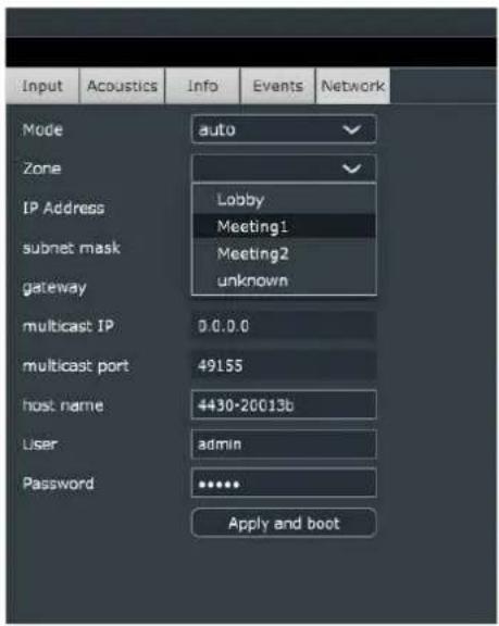
Figure 21. Assign the loudspeaker to the zone.
3. Repeat for the other zones.
After this Smart IP Manager will show the three zones created.
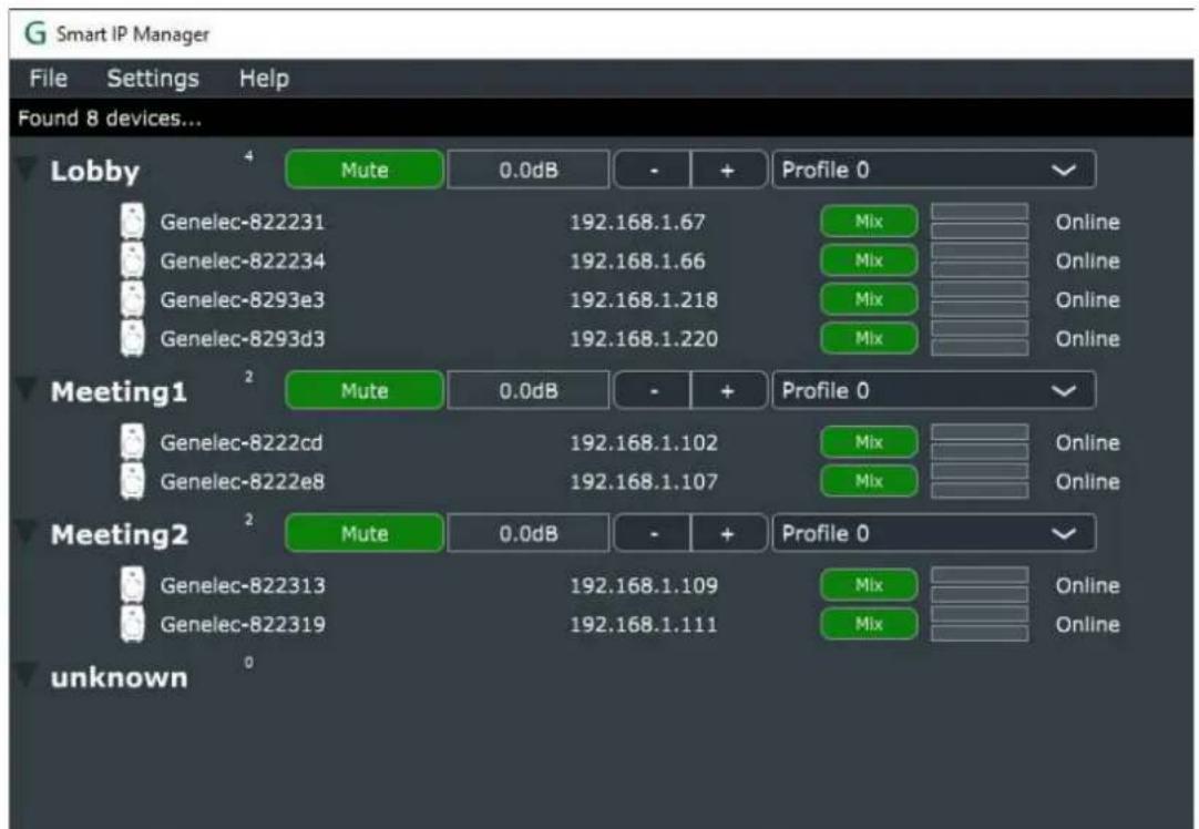
Figure 22. Three Smart IP zones created.
Zones are indicated by a bold title showing the name of the zone. The loudspeakers belonging into a zone are shown under this title. The list of loudspeakers can be collapsed.
Zone contains shared controls. These are shown after the zone name. These items contain
- MUTE button to mute or play the zone
• controls for volume (+ and – signs) - setup profile selector – the setup is collectively set for all loudspeakers in the zone

Figure 1. The zone name line, also showing the zone control functions
5.4 Loudspeaker management
Each loudspeaker is presented under the zone title, and the data shown for each loudspeaker is
- name of the receiver device (user settable using the Dante Controller)
- IP address assigned to the loudspeaker (typically provided by an automatic selection system, run by DHCP protocol) – this IP number is used for the loudspeaker control
• audio input (values are Mix, AoIP, Analog, No input)
- a status text showing any errors and warnings (this can be cleared from the File menu, option 'Clear all messages')

Figure 2. The loudspeaker information shown under the zone title; this example shows two loudspeakers called 'Genelec-8222cd' and 'Genelec-8222e8'
The exclamation mark (!) in the front of a loudspeaker icon means that the loudspeaker has something to report. The detailed messages can be seen in the ‘events’ tab. A loudspeakers power status can be STANDBY or ACTIVE, the connection status can be Online or Offline. If the loudspeaker has some problems, its internal status is ‘warning’ or in severe cases, ‘error’. Firmware update status is also shown in the same manner.

Figure 23. Loudspeaker status indicators ('!' and 'warning' text).
Table 2. Loudspeaker status icon indicators explained.
| Status icon | Meaning |
| Offline (Dark Grey) | |
| Standby (Grey) | |
| Warning (Yellow) | |
| Error (Red) | |
| Firmware update available (Green) | |
| Updating firmware (Blue) | |
| Firmware confirmation waiting (Orange) | |
| No access to this loudspeaker due to missing credentials (Black) | |
| Normal status (No icon) | |
5.5 Loudspeaker Information and Settings
Detailed information and settings related to the selected loudspeaker are shown at the right side of the Smart IP Manager window. Various information can be selected by clicking on the tabs at the top of the window:
- Input tab: the settings for the audio inputs of this loudspeaker – use these controls to see what audio stream has been set and what input channel has been selected as well as what are the settings for the analogue input; also select which audio input is used
- Acoustics tab: the acoustical controls inside this loudspeaker – use these controls to equalize the loudspeaker, set the level alignment and output delay alignment for this loudspeaker
- Info tab: general information about the selected loudspeaker and receiver
• Events tab: recent network events related to this loudspeaker
• Network tab: network-oriented settings for this loudspeaker
Some of these tabs allow user to control multiple loudspeakers at once, for example acoustic settings can be modified for all selected loudspeakers. Select multiple louspeaker using Ctrl -key and mouse click.
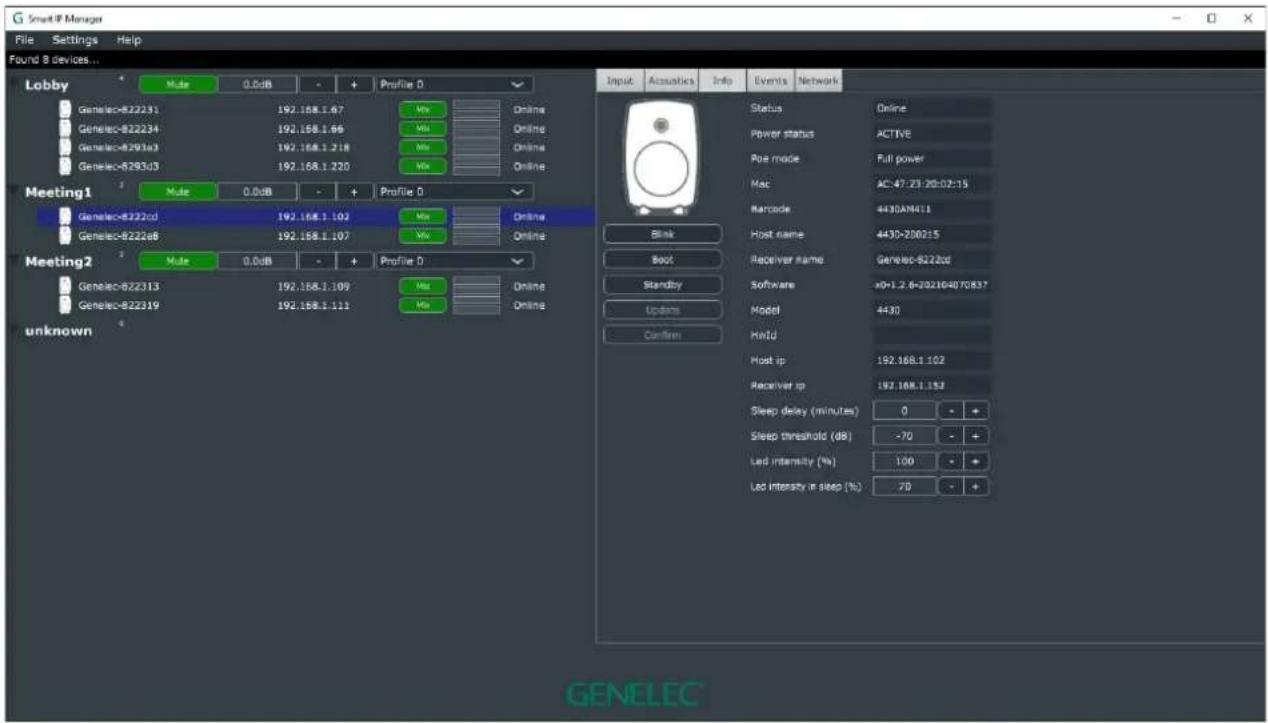
Figure 4. Loudspeaker information window, showing several tab-selectable information panels.
5.5.1 Input tab
Besides Audio-over-IP streams, the loudspeaker may also support an analog input. A loudspeaker has the following input modes
- AoIP: only Audio-over-IP stream audio is played
- Analog: only the analog input audio is played
- Mix: both the analog and AoIP audio signals are summed and played
- No input: loudspeaker does not output any signal and is silent
The input can be controlled from input tab and from the device tree with input button which toggles the input.
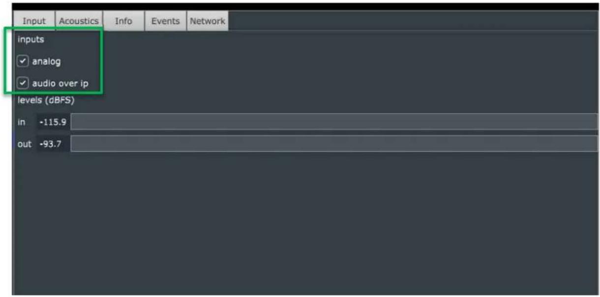
Figure 24. Input selection from the input tab.

Figure 25. Input selection from the device tree with the input button.
5.5.2 Acoustic tab
Acoustic calibration settings can be controlled in the 'Acoustics' tab. Values of all the currently selected loudspeakers are adjusted together to the values of the controls. This can be useful in speeding up the system calibration as several loudspeakers can be quickly set to the same setting.
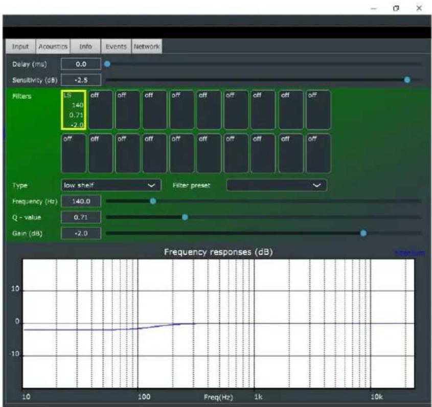
bar_line
| Frequency (Hz) | Frequency responses (dB) | | -------------- | ------------------------ | | 140.0 | 0 | | 0.71 | 0 | | -2.0 | 0 |Figure 26. Acoustic settings tab.
5.5.2.1 Delay
The delay control can be used to increase the delay of the speaker. The delay adjustment is useful in calibrating the stereo pair or immersive playback system. For these systems, the delay from all loudspeakers to the listening position should be the same. This will significantly improve the accuracy of stereo imaging of the system,
5.5.2.2 Sensitivity
This control can be used to adjust the output level of a loudspeaker. The sensitivity adjustment is useful when calibrating a stereo pair or immersive playback system. For these systems, the level from all loudspeakers to the listening position should be the same. This will significantly improve the accuracy of stereo imaging of the system,
5.5.2.3 Filters
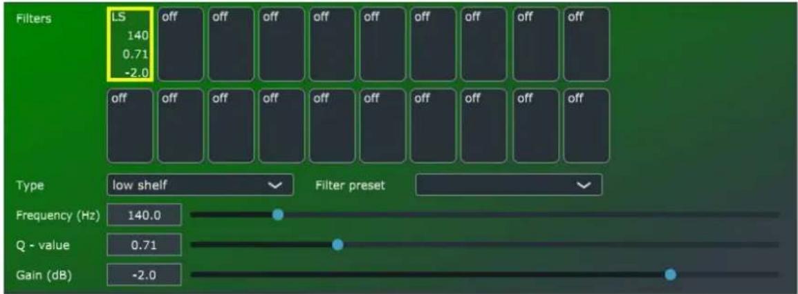
Filter buttons are used to select the filter for adjusting and to display the filter info. There are 20 filters for the user to adjust in each loudspeaker. The filter type can be selected in the dropdown menu. The values of the center frequency, Q value and gain of each filter can be adjusted using the slider controls.
Filter presets for bass cut, bass roll off and treble tilt exist. These can be used to quickly create suitable acoustic settings, but the result can still be modified using the sliders. Bass cut can be used to reduce the low frequency boost or boominess and is best used when placing the loudspeaker near a wall. When placing the loudspeaker near a corner or a double corner there will be even more low frequency boost due to the walls. Adjust the gain to -4dB or even to -6dB for best results.
For best results you should measure the room response using a calibrated microphone and an acoustical measurement tool like REW software. Based on the measurements it is possible to compensate the room response for example using filters placed on the peaking frequencies. The filter function can be selected for each filter in the tool set. Some measurement software also offers equalizer design and optimization that can be copied manually into the room equalization tool set.
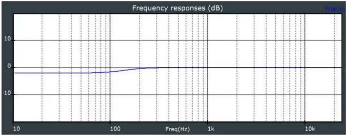
5.5.2.4 Filter Frequency Response Graph
The sum of the configured filters is displayed in a graphical format in the lower part of the component.
line
| Freq(Hz) | Frequency responses (dB) | | -------- | ------------------------ | | 10 | -2.0 | | 100 | -1.5 | | 1k | 0.0 | | 10k | 0.0 |5.5.2.5 Storing Acoustic Settings to Profile Preset
Acoustic settings can be stored into the loudspeaker. There are five profile preset memory slots in a loudspeaker for this purpose. To store settings the profile preset:
- Use the right mouse click on the zone caption text line and select the "Store preset" option in the dropdown menu.

-
Select the target profile preset you want to use for your settings in the popup shown. The preset name can be edited to change the name to what you want.
-
Click the 'Store' button to save the current acoustic and input settings into every loudspeaker in the selected zone.
-
Close the window.
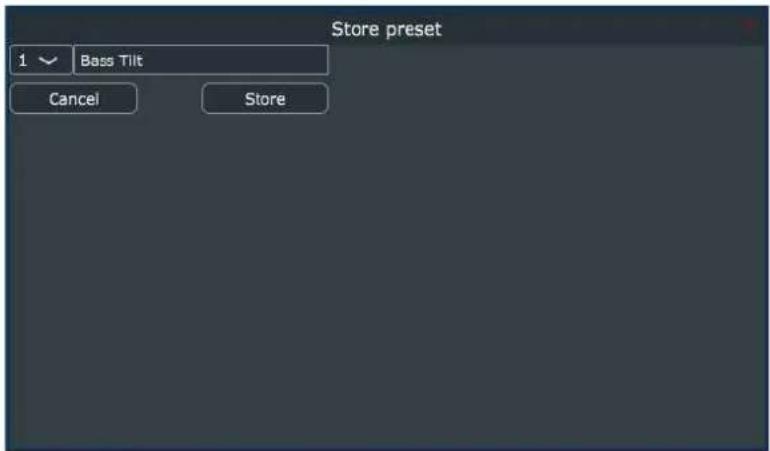
Figure 27. Store preset window.
Profiles can be used to configure different setups for example for different listening positions or different numbers of loudspeakers to be active. The input setting "no input" can be used to stop the loudspeaker from participating in sound reproduction, to make it silent.
The profile presets can be recalled easily to load the stored settings with the zone control.
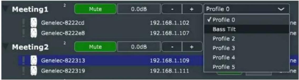
Figure 28. Loading the profile preset.
5.5.3 Info tab
The Info tab is used to view the status of the Smart IP loudspeaker. It can be also used to update the Smart IP loudspeaker firmware and set ISS settings. Next chapters will show more details.
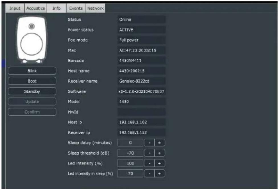
Figure 29. Info tab.
5.5.3.1 Identify the loudspeaker
The physical location loudspeaker in the room can be identified by clicking the 'Blink' button. This causes the loudspeaker to blink its front panel LED for a while. The blinking will automatically stop after some time.
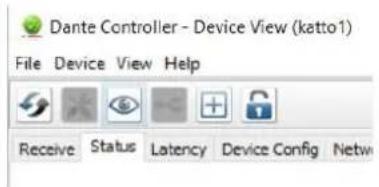
Identifying the loudspeaker is also possible using the Dante Controller. The loudspeaker LED can blink when the "eye" button in the detail window is clicked. The LED will blink for a while and will automatically stop after some time.
5.5.3.2 Booting the loudspeaker
The loudspeaker can be booted by clicking the 'Boot' button. The Smart IP loudspeaker turns OFF and will drop from the network until it has booted.
5.5.3.3 Put the loudspeaker to standby
The loudspeaker can be put to standby mode by clicking the 'Standby' button. When the loudspeaker is in the standby mode, it can be woken up by clicking the 'Wake up' button – this is the same button but with a different text to indicate the action.
5.5.3.4 Update the Firmware of the Loudspeaker
The loudspeaker shows a green notification icon when a new firmware is available in the Genelec Cloud. To update the firmware
- Select the loudspeaker to be updated in the device tree.
- Open the 'info' tab and click the 'Update' button. After this, the firmware is uploaded into the loudspeaker and the icon turns blue. An alternate way to update is to right-click the loudspeaker line and then select the 'Update firmware'.
- When the upload of firmware has finished, the loudspeaker boots. In this situation the loudspeaker goes offline for a moment. When the loudspeaker wakes up and reappears on the network an orange icon is indicating that the update has been successful.
- Confirm the update by opening the 'Open info' tab and click the 'Confirm' button. This is necessary to keep the new firmware. An alternate way to check is to right-click the loudspeaker and then select the 'Confirm update'. If the confirmation is not done, the loudspeaker reverts back to the previous firmware version after the next reboot.
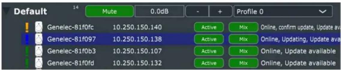
Figure 30. Firmware update status indicators.
NOTE: Dante audio receiver firmware update is done separately if needed, and the update is accomplished using the Dante Controller software. Consult the Dante Controller documentation on how to do this.
5.5.3.5 Loudspeaker information
- Status: Offline, Online, Standby, Warning, Error (for detailed information about warnings and errors can be found from the log in the events tab).
• Power Status: Active, Standby - PoE Mode: Full power (PoE+: 30W), Limited Power (PoE: 15W)
• Mac: MAC address of controller CPU - Barcode: Serial number
- Host name: Genelec loudspeaker name
- Receiver name: Dante device name
- Software: Software revision string
• Model: Loudspeaker model - HwId: Hardware id
- Host IP: Genelec/host IP address (used to control)
- Receiver IP: Dante device IP address (used to Dante control)
5.5.3.6 ISS Settings
A Smart IP loudspeaker comes with an ISS (Intelligent Signal Sensing) power saving feature, and ISS can be configured to enter the loudspeaker in a standby mode automatically when there is no active audio signal at the loudspeaker input. The settings of this feature can be set in the 'Info' tab.
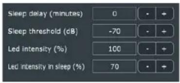
Figure 31. ISS settings.
To set ISS active for a loudspeaker:
- Set Sleep Delay to a value greater than 0. The zero value (0) is the default and means the ISS is OFF and the loudspeaker never goes to power save. The Sleep delay specifies the time after which the loudspeaker enters into the low power sleep mode if there is no audio input signal.
- The Sleep Threshold specifies the minimum input signal level for detecting active input. Exceeding this level is needed to keep the loudspeaker awake.
- LED intensity in Sleep specifies the led brightness in the low power consumption sleep mode. No light is selected with value 0 and maximum brightness is selected with value 100.
The loudspeaker wakes up from the sleep state automatically when the audio signal level exceeds the Sleep threshold level at the configured input.
5.5.3.7 LED Intensity
Smart IP loudspeaker's front panel LED intensity in the normal operating mode can be set in the 'Info' tab. The value can be set from 0 to 100. Value 0 means that the LED is OFF and 100 means that LED has the maximum brightness.

Figure 32. Front panel LED Intensity setting.
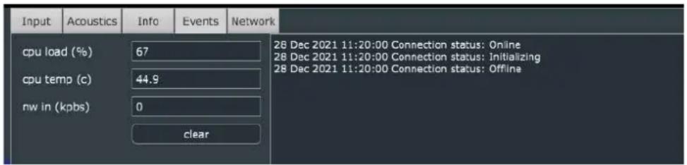
5.5.4 Events tab
The loudspeaker events can be checked in the Events tab. By looking at the events It can be used to view what happens with loudspeaker during the use.
- CPU load: tells how busy the loudspeaker CPU is. Value ranges from 0% at idle to 100% at full load; typically the value is between 50-70.
- CPU temp: tells a temperature of the CPU inside the loudspeaker; typically the temperature varies in the range 40 – 80 C.
- Nw in (kbps): tells how much network traffic the loudspeaker CPU is receiving. If the incoming traffic is very high this may indicate unwanted multicast traffic flooding all the ports in an IP switch.
5.5.5 Network tab
This tab shows all the network related settings.
- Mode: selects how the IP address for loudspeakers is set. By default, a loudspeaker is configured to use an “automatic” IP address. When there is a DHCP server in the network, a loudspeaker uses the IP address assigned by the DCHP server. If a DHCP is not found, the loudspeaker uses an auto-IP (in the IP address range 169.254.xxx.xxx). A loudspeaker can also be configured to use a static IP address.
- Zone: sets the zone where the loudspeaker belongs.
- IP Address: shows the current IP address of the loudspeaker.
- Subnet mask: shows the current subnet mask of the loudspeaker.
- Multicast IP: shows the current multicast IP address of the loudspeaker (this is not used currently).
- Multicast port: shows the current multicast port of the loudspeaker (this is not used currently).
- Host name: name of the loudspeaker – the default name is set as [loudspeaker model – 3 last bytes of MAC address].
- User: shows the user name set to enable access to the loudspeaker settings (default user name is 'admin')
- Password: shows the password enabling access to the loudspeaker settings (the default password id 'admin')
NOTE: to confirm any changes, click 'Apply' and click the 'boot' button.
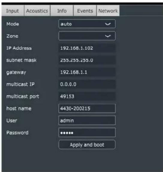
Figure 33. Network tab.
5.5.5.1 Zone Credentials
The zone credentials can be same for all zones. However, some times access to the zones need to be limited and different credentials are needed. The default credentials of can be also changed be following instructions below.
To change the credentials to access a zone:
-
Select all the loudspeakers in the zone. The credentials of all loudspeakers in the zone must be same.
-
Open the Network tab.
-
Enter the Username and Password you want to have for this zone.
- Apply the changes to zone credentials by clicking 'Apply' and click the 'boot' button.
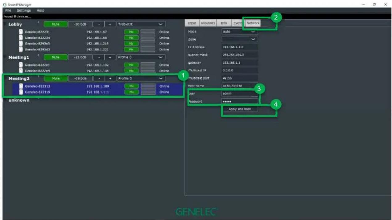
Figure 34. Setting the zone credentials.
After applying the settings, the loudspeakers will be booted. Later on the zone list will show as "unknown" zone, the loudspeakers which credentials were changed are now listed under that with "Unauthorized" status. To open access, follow instructions in next chapter or 20 or change the Smart IP Manager system credentials from Audio network settings (Audio network settings).
5.5.5.2 Access to Unauthorized Loudspeakers
When loudspeaker credentials do not match the user default credentials in audio network settings, the loudspeakers cannot be accessed. These loudspeakers are indicated with a black exclamation mark (!) and show ‘unauthorized’ status and are grouped under an ‘unknown’ zone as shown in Figure 35.
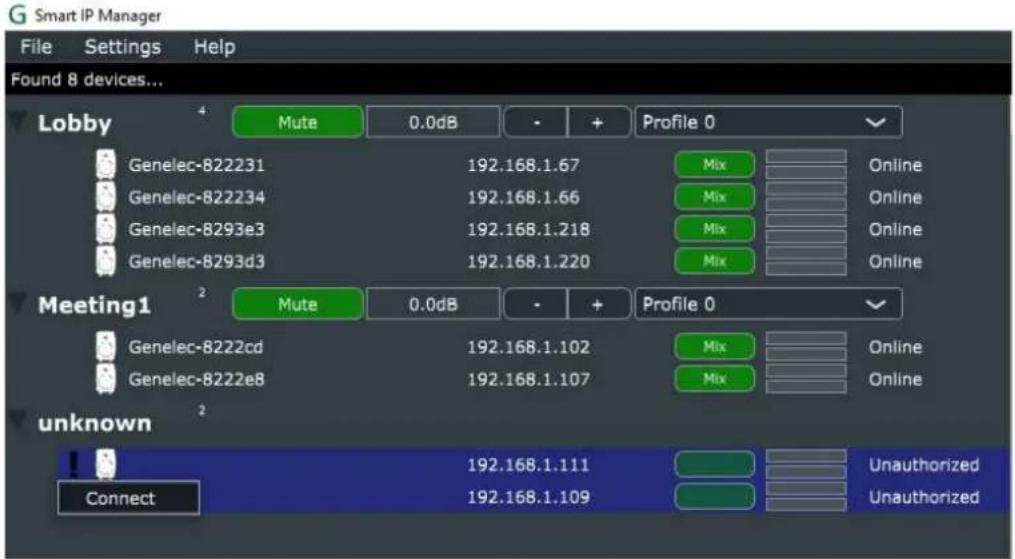
Figure 35. Unauthorized loudspeakers.
If you know the credentials for a zone it is possible to connect the loudspeakers in the zone. This is done by right mouse click => select 'connect' and give the credentials when a popup asking credentials is shown. After a successful connection, the loudspeakers in the zone are shown and you can control the loudspeakers.
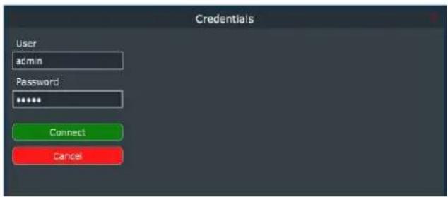
Figure 36. Giving the credentials to authorize access to a zone.
6 How to configure and use the Smart IP Controller App
Smart IP Controller is a mobile device app for daily management of the zones in a Smart IP system. This app is easy to install and configure to any Apple iOS or Android phone or tablet. The main functions allow adjusting the volume level and turning zones on and off.
The Smart IP Controller app can be downloaded from Google Play Store and Apple Store.
To use the app, first at least one zone is configured into the app. The Controller app first suggests using the Default Zone. If you have not configured any zones using the Smart IP Manager, this is the method you will use.
After configuring other zones using the Smart IP Manager, you will use the usernames and passwords for these other zones when you configure them.
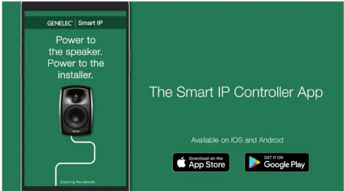
Figure 37. Smart IP Controller app.
6.1 WiFi Setup for the Smart IP Controller App
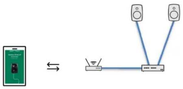
The Controller app requires a Wi-Fi router on the same network with the Smart IP loudspeakers (for an example, see Figure 38). Being on the same network frequently means that the first three octets of the IP address for all the IP devices on the network are the same.
For example, your network address range may contain IP addresses between
192.168.0.1 to 192.168.0.127
and in this example, only the last octet changes and is unique to each device.
If your network is using automatic assignment of the IP addresses, then all devices are automatically on the same network. Typically, a method called DHCP is used for automatic IP address assignment, and this method is usually the default method for small networks.
In some cases, it may be necessary to manually set the IP address for each device. When you do this, two devices can never have exactly the same IP address even if the start part of the IP address must be the same for all devices. Then, you assign a unique number to each device using the last octet.
flowchart
graph TD
    subgraph_Meeting_Room1["Meeting Room 1"]
        A1["Speaker"] --> B1["Lobby"]
        A2["Lbox"] --> B1
        A3["Lbox"] --> B1
        A4["Lbox"] --> B1
        A5["Lbox"] --> B1
        A6["Lbox"] --> B1
        A7["Lbox"] --> B1
    end
    subgraph_Meeting_Room2["Meeting Room 2"]
        B1 --> C1["Lobby"]
        B2["Lbox"] --> C1
        B3["Lbox"] --> C1
        B4["Lbox"] --> C1
        B5["Lbox"] --> C1
        B6["Lbox"] --> C1
    end
    subgraph_Lobby_Lobby["Leather"]
        C1 --> D1["Lobby"]
        C2 --> D1
        C3 --> D1
        C4 --> D1
        C5 --> D1
        C6 --> D1
    end
Figure 38. Network cabling example.
6.2 Enabling Smart IP Controller App on your WLAN
After installing the Smart IP Controller app, configure the app to control the zones. The App can be configured to control only one or several zones, depending on the intended use of the App. When you want to limit access to a zone, give names and passwords (access credentials) to all zones. Keep the credentials secret, and only configure those zones in the app that you want to give access to.
Make sure that the device with Smart IP Controller app is connected to the same network with Smart IP loudspeakers. Mobile devices typically connect using WLAN. This is done in your mobile device IP address settings. If your WLAN is using DHCP this usually happens automatically. Some mobile devices use the mobile phone network for Internet connectivity, and then the WLAN service in your mobile device may not be turned on. To connect the Smart IP Controller app you must turn
on the WLAN service and assign it to an IP address in the same network with the Smart IP loudspeakers.
flowchart
graph LR
    A["Smartphone with Ethernet"] <--> B["Router"]
    B --> C["Speaker 1"]
    B --> D["Speaker 2"]
Figure 39. Genelec Smart IP control network on simple network containing a WLAN access point, IP switch with PoE output to Smart IP loudspeakers.
6.3 Configuring Smart IP Controller App
Follow these steps to configure each zone. To add zone definitions (shown in Figure 47) to the Smart IP Controller do the following:
- Launch the Smart IP Controller app. Wait until it has found all the loudspeakers in the network. Ensure that the number of speakers found matches the actual number of loudspeakers and zones. Then proceed. If not, try rescanning.
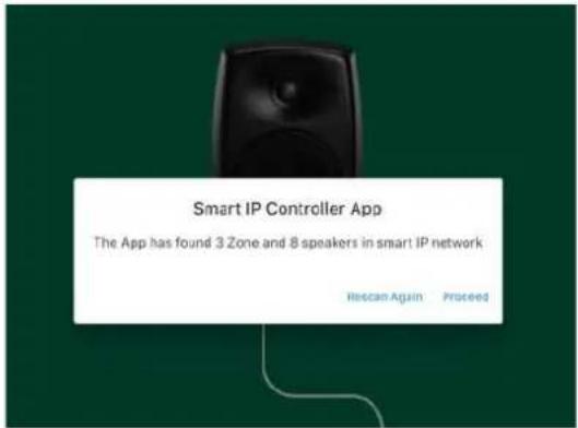
Figure 40. The number of Smart IP zones and speakers found by Smart IP Controller app.
After finding all the loudspeakers, you are now ready to start entering the configurations.
- Start adding the first zone by clicking the '+' button.
If it exists, the 'Default zone' will be shown.
To add more zones besides the Default zone, jump to step 9 and then continue from step 4. Continue until all zones you want to show have been set up.
If the Default zone is the only zone you want to have, the zone addition process is now complete, you can move to using the Controller app controls for the Default zone.
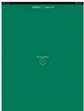
Figure 41. The main page without any zones. Clic + icon to create a zone.
- Type in the zone name, for example 'Meeting1' (Name is case sensitive).
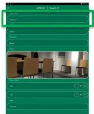
Figure 42. Zone name field.
- Give the username and password needed to access this zone.
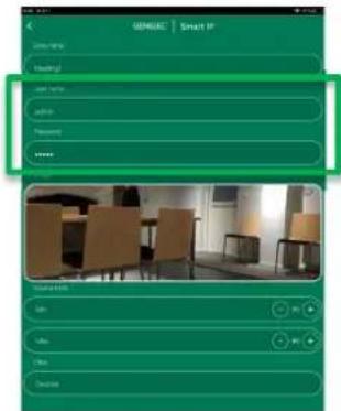
Figure 43. Zone credentials.
- Add an optional image of the zone. Adding an image makes it easier to identify the zone by just seeing the image.
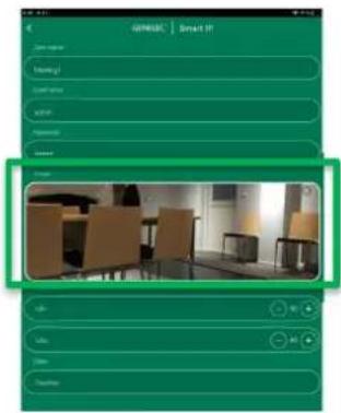
Figure 44. Click to add an image for the zone.
- Volume level operation ranges can be set e.g. to limit maximum volume.
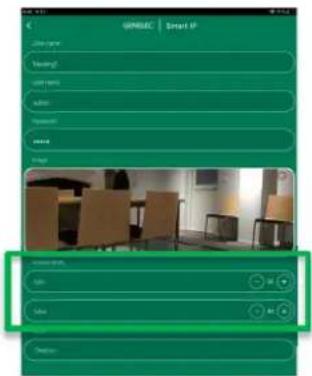
Figure 45. Volume limit for the volume control.
- Confirm settings.
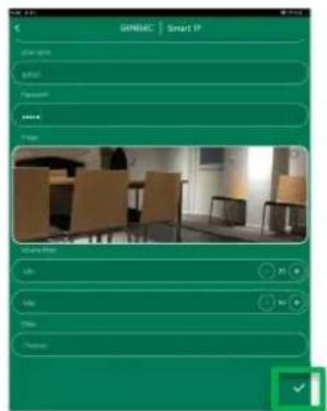
Figure 46. Confirmation button.
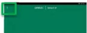
- To add more zones, click three dots on the left top corner and select Access to New Zone and repeat steps 4-8 for all needed zones.
-
To edit controller settings, click three dots on the left top corner and select Controller Settings.
-
Hide Default Zone; If selected the Default zone on the main page will be hidden if zone exists.
- Hide Not Assigned Zone; If selected the zones where the Controller has no access will be hidden.
- Hide Zone Images; If selected the zone images will be hidden to make the main page controls minimal.
- Enable Zone Editing: If selected the zone can be edited by clicking the zone edit icon on the main page.
- Enable Master Controls; If selected the master control panel will be visible on the main page. It enables to power off or mute all zones at once.
- Reset Application; Can be used to clear the Smart IP Controller. Will delete all zones and settings after confirmed.
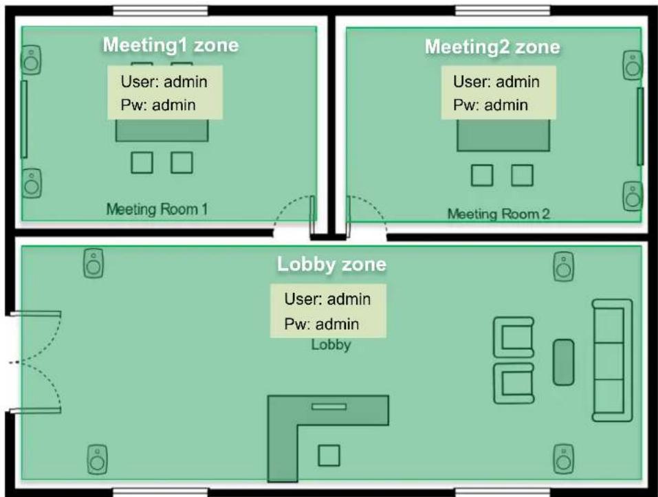
Figure 47. Each room has its own zone.
6.4 Daily Use of Smart IP Controller App
Each zone is presented by the zone view. The Figure shows a zone called 'Lobby'. In this view you can see the zone name, and the number of Smart IP loudspeakers in this zone.
The controls affect all the loudspeakers inside this zone. The controls for the zone include
• volume control by pressing + or - buttons
- power on/off
- mute the loudspeakers
The animated bars show if audio is playing in the zone.
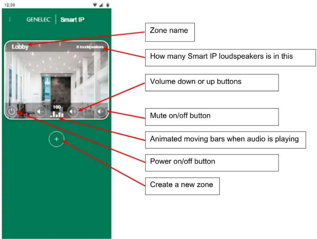
Figure 48. Zone view for daily use.
7 Frequently Asked Questions
7.1 Where can I find more information about Dante?
Dante FAQ's can be found from https://www.audinate.com/learning/faqs?lang=eng Audinate provides also good training for the AV networks through the Dante Certification Program and it's highly recommended for all who works with AV networks, Dante Certification Program is available from https://www.audinate.com/learning/training-certification/dante-certification-program?lang=eng
7.2 Why can't I select an audio stream in the Dante Controller matrix?
The stream cannot be selected if the audio sample rate and the loudspeaker operating sample rate do not match. Are source's audio sample rate and loudspeaker sample rate same?
7.3 Why can't I edit/control loudspeakers that are listed with Smart IP Manager?
Network discovery finds Smart IP loudspeaker even that a computer and loudspeakers are in different subnet. Check that the computer and loudspeakers are on same subnet.
7.4 Why a Smart IP loudspeaker won't power up?
Check that PoE power is available. Is the PoE switch powered ON? Is the PoE budget of PoE switch exceeded? If using a PoE injector check that it's powered ON.
7.5 Does Smart IP loudspeaker support AES67 streams?
Yes. AES67 support can be enabled from Dante Controller software as described in chapter 4.7.
7.6 Is there Smart IP subwoofers available?
At the moment no. However other Genelec subwoofer model can be used with e.g. Dante AVIO adapter. In this case Smart IP Controller or API cannot be used to control the system volume. In many case the audio source can control audio level and it's not a problem.
7.7 How can I reset the Smart IP loudspeaker to the factory state?
Press the power button of the loudspeaker for 10 seconds (the loudspeaker will play a short beep) and release the button. Loudspeaker will reset all network and acoustic settings.
GENELEC®
Power to the speaker Power to the installer
International enquiries
Genelec, Olvitie 5
FI 74100, lisalmi, Finland
Phone +358 17 83881
Fax +358 17 812 267
Email genelec@genelec.com
In Sweden
Genelec Sweden
Tureholmsvägen 12
SE-125 35 Älvsjö
Sweden
Phone +46 8 449 5220
Email sweden@genelec.com
In the USA
Genelec, Inc., 7 Tech Circle
Natick, MA 01760, USA
Beijing Genelec Audio Co.Ltd
Room 101, Building B33
Universal Business Park
No. 10 Jiuxianquiao Road
Chaoyang District
Beijing 100015, China
Phone +86 10 5823 2014
Phone +86 400 700 1978
Email genelec.china@genelec.com
In Japan
Genelec Japan Inc
2-22-21 Akasaka
Minato-ku
JP-107-0052 Tokyo
Japan
Phone +81 3 6441 0591
Email genelec.japan@genelec.com
- Table of Contents
- Introduction
- System Components
- Selecting IP switch devices
- Capacity / bandwidth
- PoE support
- PoE budget calculation
- Network Structure
- Getting Started
- System Control and Zone Plan
- Positioning and mounting the loudspeakers
- Connection Analog Input
- Connecting Ethernet and PoE to loudspeakers
- Downloading and Installing Smart IP Manager
- Downloading and Installing Smart IP Controller
- Setting Up IP Audio Stream
- Using Smart IP Manager
- Menus
- File menu
- Settings menu
- Help menu
- Audio network settings
- Zones
- Default Zone
- Creating Zones
- Assigning Loudspeakers to the Zone
- Repeat for the other zones.
- Loudspeaker management
- Loudspeaker Information and Settings
- Input tab
- Acoustic tab
- Delay
- Sensitivity
- Filters
- Filter Frequency Response Graph
- Storing Acoustic Settings to Profile Preset
- Info tab
- Identify the loudspeaker
- Booting the loudspeaker
- Put the loudspeaker to standby
- Update the Firmware of the Loudspeaker
- NOTE: Dante audio receiver firmware update is done separately if needed, and the update is accomplished using the Dante Controller software. Consult the Dante Controller documentation on how to do this.
- Loudspeaker information
- ISS Settings
- LED Intensity
- Events tab
- Network tab
- Zone Credentials
- Access to Unauthorized Loudspeakers
- How to configure and use the Smart IP Controller App
- WiFi Setup for the Smart IP Controller App
- Enabling Smart IP Controller App on your WLAN
- Configuring Smart IP Controller App
- Daily Use of Smart IP Controller App
- Frequently Asked Questions
- Where can I find more information about Dante?
- Why can't I select an audio stream in the Dante Controller matrix?
- Why can't I edit/control loudspeakers that are listed with Smart IP Manager?
- Why a Smart IP loudspeaker won't power up?
- Does Smart IP loudspeaker support AES67 streams?
- Is there Smart IP subwoofers available?
- How can I reset the Smart IP loudspeaker to the factory state?
- GENELEC®
- International enquiries
- In Sweden
- In the USA
- In Japan
Brand : GENELEC
Model : 4430A
Category : Monitor