
4020C - Monitor GENELEC - Free user manual and instructions
Find the device manual for free 4020C GENELEC in PDF.


| Product Type | Active Studio Monitor |
| Model | 4020C |
| Brand | Genelec |
| Driver Configuration | Two-way: 4" woofer, 0.75" tweeter |
| Frequency Response | 56 Hz - 24 kHz (-6 dB) |
| Amplifier Power | 50 W per channel (woofer and tweeter) |
| Maximum SPL | 100 dB SPL @ 1m (peak) |
| Input Connectors | 1x XLR balanced, 1x RCA unbalanced |
| Input Impedance | 10 kOhm (balanced), 10 kOhm (unbalanced) |
| Controls | Volume, bass tilt, treble tilt, desktop reflex |
| Dimensions (H x W x D) | 245 x 151 x 134 mm (9.6 x 5.9 x 5.3 in) |
| Weight | 3.2 kg (7.1 lb) per speaker |
| Power Consumption | Idle: 10 W, Max: 80 W |
| Power Supply | Internal, 100-240 V AC, 50/60 Hz |
| Enclosure Type | MDF with protective metal grille |
| Cabinet Color | Black or white (optional) |
| Mounting Options | Rubber feet, threaded mounting point (M6) |
| Room Compensation | Onboard dip switches for bass and treble |
| Protection | Overload, thermal, short-circuit |
| Recommended Placement | Near-field, on stands or desk (with isolation pads) |
| Accessories Included | Power cable, user manual, rubber feet |
| Standards Compliance | CE, FCC, RoHS |
Frequently Asked Questions - 4020C GENELEC
User questions about 4020C GENELEC
0 question about this device. Answer the ones you know or ask your own.
Ask a new question about this device
Download the instructions for your Monitor in PDF format for free! Find your manual 4020C - GENELEC and take your electronic device back in hand. On this page are published all the documents necessary for the use of your device. 4020C by GENELEC.
USER MANUAL 4020C GENELEC
natural_image
Close-up of a textured surface with hexagonal patterns and a smooth curved edge (no text or symbols)General
The bi-amplified Genelec 4020C is an extremely compact two way active loudspeaker designed for fixed installations. As an active loudspeaker, it contains drivers, power amplifiers, active crossover filters and protection circuitry. The 4020C is designed for indoor use only, in temperatures between 15 to 35 degrees Celsius and relative humidity between 20 % and 90 %.
The MDE ^TM (Minimum Diffraction Enclosure ^TM ) loudspeaker enclosure is made of die-cast aluminium and shaped to reduce edge diffraction. Combined with the advanced Directivity Control Waveguide ^TM (DCW ^TM ), this design provides excellent frequency balance in difficult acoustic environments.
Positioning the loudspeaker
Each 4020C is supplied with an integrated amplifier unit, mains cable, a 3-pin balanced Euroblock connector for audio signal, a keyhole type wall-mount and an operating manual. After unpacking, place the loudspeaker in its required listening position, taking note of the line of the acoustic axis. The axis should be pointed towards the center of the listening area.
Connections
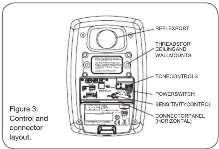
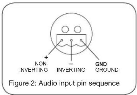
Before connecting up, ensure that the loudspeakers and the signal source have been switched off. The power switch of the 4020C is located on the back panel (see Figure 3). Connect the loudspeaker to an earthed mains connection with the supplied mains cable. Never connect the loudspeaker to an unearthed mains supply or using an unearthed mains cable. Audio input is via a 10 kOhm balanced connector. The pin sequence of the connector is shown in Figure 2.
4020C
Active Loudspeaker
Connect the signal cable to the 3-pole plug provided with the loudspeaker and secure the connections by tightening the screws on each pole. Push the plug into the connector on the loudspeaker.
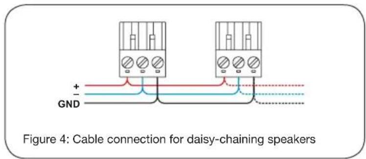
If you want to daisy-chain multiple loudspeakers, simply connect a second signal cable to the plug and use it to route the signal to the next loudspeaker (see Figure 4).
Never connect the 4020C to the loudspeaker outputs of a power amplifier or an integrated amplifier or receiver.
Once the connections have been made, the loudspeakers are ready to be switched on.
ISS™ Autostart
The automatic power saving function ISS (Intelligent Signal Sensing) can be activated by setting the “ISS” switch on the back panel to “ON.” Automatic powering down to standby mode happens after a certain time when playback has ended. The power consumption in standby mode is typically less than 0.5 watts. Playback will automatically resume once an input signal is detected from the source.
There is a slight delay in the automatic powering up. If this is undesirable, the ISS ^TM function can be disabled by setting the “ISS” switch on the back panel to “OFF.” In this mode, the loudspeaker is powered on and off using the power switch on the back panel.
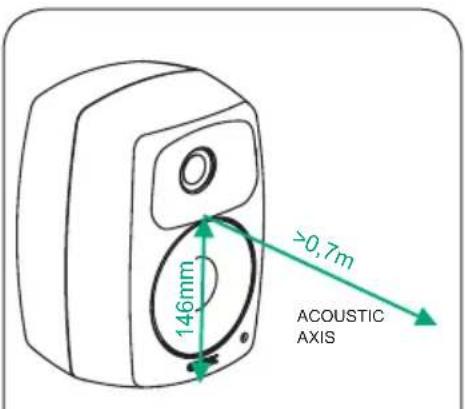
Figure 1: Location of the acoustic axis
Level control
The input sensitivity of the loudspeaker can be matched to the output of the signal source by adjusting the level control on the rear panel.
Setting the tone controls
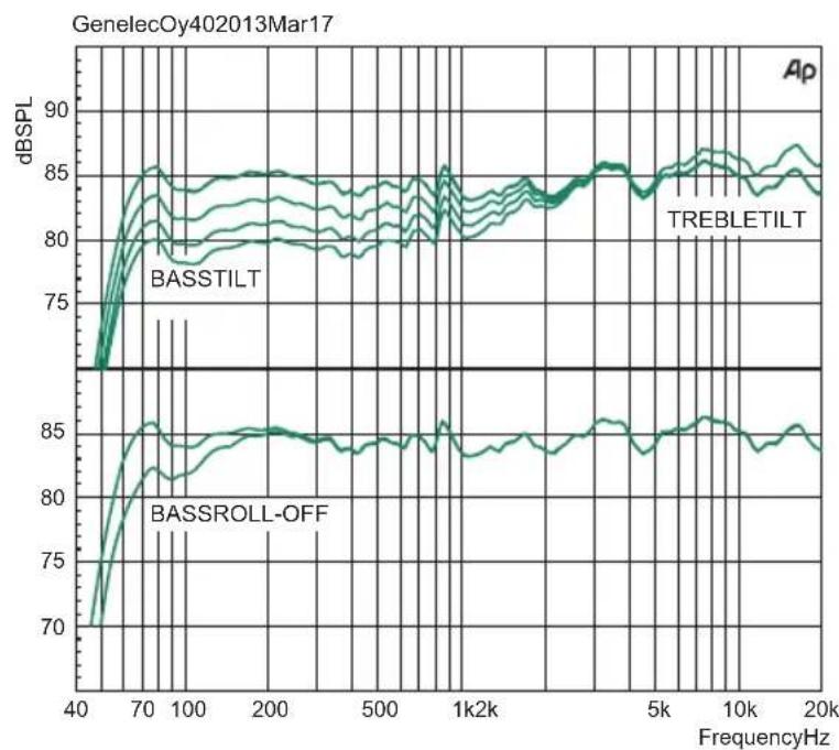
The frequency response of the Genelec 4020C can be adjusted to match the acoustic environment by setting the tone control switches on the rear panel. The controls are “Treble Tilt”, “Bass Tilt” and “Bass Roll-Off”. An acoustic measuring system such as WinMLS or comparable is recommended for analyzing the effects of the adjustments, however, careful listening with suitable test recordings can also lead to good results if a test system is not available. Table 1 shows some examples of typical settings in various situations.
Figure 5 shows the effect of the controls on the anechoic response.
Treble Tilt
The Treble Tilt control (switch 2) boosts the treble response of the loudspeaker at frequencies above 4 kHz by +2 dB, which can be used for compensating for the high frequency loss occurring at long listening distance, off-axis listening or when the loudspeaker is placed behind a screen or decorative cloth.
Bass Tilt
The Bass Tilt control offers three attenuation levels for the bass response of the loudspeaker below 2 kHz, usually necessary when the loudspeakers are placed near a wall or other room boundaries.
| Loudspeaker Mounting Position Treble Tilt Bass Tilt Bass Roll-Off | |||
| Flat anechoic response OFF OFF OFF | |||
| Free standing in a damped room OFF OFF OFF | |||
| Free standing in a reverberant room OFF -2 dB OFF | |||
| Near field or desktop OFF -4 dB OFF | |||
| Near to a wall | OFF -6 dB | OFF |
Table 1: Suggested tone control settings for differing acoustical environments
The attenuation levels are -2 dB (switch 4 "ON"), -4 dB (switch 5 "ON") and -6 dB (both switches "ON").
Bass Roll-Off
Bass Roll-Off (switch 3) activates a -4 dB filter to the lowest bass frequencies (65 Hz). This can be used for compensating excessively heavy bass reproduction typically caused by loudspeaker placement near room boundaries.
The factory setting for all tone controls is “OFF” to give a flat anechoic response. Always start adjustment by setting all switches to “OFF” position. Measure or listen systematically through the different combinations of settings to find the best frequency balance.
Mounting considerations
Align the loudspeakers correctly
Always place the loudspeakers so that their acoustic axes (see figure 1) are aimed towards the center of the listening area. Only vertical placement is preferred, as it minimises acoustical cancellation problems around the crossover frequency.
Minimise reflections
Acoustic reflections from objects close to the loudspeakers like walls, cabinets etc. can cause unwanted colouration or blurring of the sound image. These can be minimised by placing the loudspeaker clear of reflective surfaces.
Minimum clearances
Sufficient clearance for cooling of the amplifier and functioning of the reflex port must be ensured if the loudspeaker is installed in a restricted space such as a cabinet or integrated into a wall structure. The surroundings of the loudspeaker must always be open to the listening room with a minimum clearance of 3 centimeters ( 1^3/_16 ) behind, above and on both sides of the loudspeaker. The space adjacent to the amplifier must either be ventilated or sufficiently large to dissipate heat so that the ambient temperature does not rise above 35 degrees Celsius (95°F)
Mounting options
The Genelec 4020C offers several mounting options: On the base of the loudspeaker is a 3/8" UNC threaded hole compatible with a standard microphone stand. On the rear there are two M6x10 mm threaded holes for Omnimount ^® size
20.5 brackets or the keyhole wall mount adapter provided with the loudspeaker. See Genelec Accessories Catalogue on www.genelec.com for a complete list of mounting hardware options.
Maintenance
No user serviceable parts are to be found within the amplifier unit. Any maintenance or repair of the 4020C unit should only be undertaken by qualified service personnel.
Safety considerations
Although the 4020C has been designed in accordance with international safety standards, the following warnings and cautions should be observed to ensure safe operation and to maintain the loudspeaker under safe operating conditions:
- Servicing and adjustment must only be performed by qualified service personnel. The loudspeaker must not be opened.
- Do not use this product with an unearthed mains cable or an unearthed mains connection as this may compromise electrical safety.
- Do not expose the loudspeaker to water or moisture. Do not place any objects filled with liquid, such as vases on the loudspeaker or near it.
- This loudspeaker is capable of producing sound pressure levels in excess of 85 dB, which may cause permanent hearing damage.
- Free flow of air behind the loudspeaker is necessary to maintain sufficient cooling. Do not obstruct airflow around the loudspeaker.
- Note that the amplifier is not completely disconnected from the AC mains service unless the mains power cord is removed from the amplifier or the mains outlet.
Guarantee
This product is guaranteed for a period of two years against faults in materials or workmanship.
Refer to supplier for full sales and guarantee terms.
Compliance to FCC rules
This device complies with part 15 of the FCC Rules. Operation is subject to the following conditions:
- This device may not cause harmful interference, and
- This device must accept any interference received, including interference that may cause undesired operation.
Note: This equipment has been tested and found to comply with the limits for a Class B digital device, pursuant to part 15 of the FCC Rules. These limits are designed to provide reasonable protection against harmful interference in a residential installation. This equipment generates, uses and can radiate radio frequency energy and, if not installed and used in accordance with the instructions, may cause harmful interference to radio communications. However, there is no guarantee that interference will not occur in a particular installation. If this equipment does cause harmful interference to radio or television reception, which can be determined by turning the equipment off and on, the user is encouraged to try to correct the interference by one or more of the following measures:
- Reorient or relocate the receiving antenna.
- Increase the separation between the equipment and receiver.
- Connect the equipment into an outlet on a circuit different from that to which the receiver is connected.
- Consult the dealer or an experienced radio/TV technician for help.
Modifications not expressly approved by the manufacturer could void the user's authority to operate the equipment under FCC rules.
line
| FrequencyHz | BASSTILT | TREBLETILT | BASSROLL-OFF | | ----------- | -------- | ---------- | ------------ | | 40 | 70 | 70 | 70 | | 70 | 85 | 85 | 85 | | 100 | 85 | 85 | 85 | | 200 | 85 | 85 | 85 | | 500 | 85 | 85 | 85 | | 1k2k | 85 | 85 | 85 | | 5k | 85 | 85 | 85 | | 10k | 85 | 85 | 85 | | 20k | 85 | 85 | 85 |Figure 5. The curves show the effect of the "Bass Tilt", "Treble Tilt" and "Bass Roll-Off" controls on the free field response of the 4020C.
line
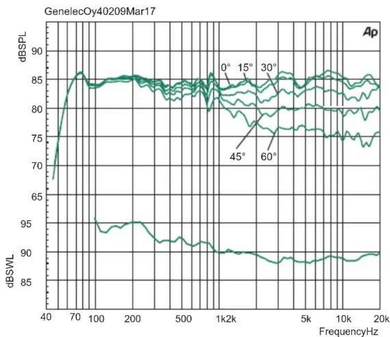
| FrequencyHz | dBSPL (0°) | dBSPL (15°) | dBSPL (30°) | dBSPL (45°) | dBSPL (60°) | dBSWL | | ----------- | ---------- | ----------- | ----------- | ----------- | ----------- | ----- | | 40 | 68 | 68 | 68 | 68 | 68 | 90 | | 70 | 86 | 86 | 86 | 86 | 86 | 95 | | 100 | 85 | 85 | 85 | 85 | 85 | 94 | | 200 | 85 | 85 | 85 | 85 | 85 | 95 | | 500 | 84 | 84 | 84 | 84 | 84 | 92 | | 1k2k | 83 | 83 | 83 | 83 | 83 | 90 | | 5k | 82 | 82 | 82 | 82 | 82 | 89 | | 10k | 81 | 81 | 81 | 81 | 81 | 89 | | 20k | 80 | 80 | 80 | 80 | 80 | 90 |Figure 6. Frequency responses at 0, 15, 30, 45 and 60 degree angles and power response in full space. Input level -20 dBu.
SYSTEM SPECIFICATIONS
Lower cut-off frequency, -6 dB: ≤ 56 Hz
Upper cut-off frequency, -6 dB: ≥ 25 kHz
Accuracy of frequency response:
$$ 6 2 \mathrm{Hz} - 2 0 \mathrm{kHz} (\pm 2. 5 \mathrm{dB}) $$
Maximum short term sine wave acoustic output on axis in half space, averaged from 100 Hz to 3 kHz:
$$ @ 1 \mathrm{m} \geq 1 0 0 \mathrm{dB} \text { SPL } $$
Maximum long term RMS acoustic output in same conditions with IEC weighted noise (limited by driver unit protection circuit): @ 1 m ≥ 93 dB SPL
Maximum peak acoustic output per pair @ 1 m distance with music material: ≥ 107 dB
Self generated noise level in free field @ 1 m on axis: < 5 dB (A-weighted)
Harmonic distortion at 85 dB SPL @ 1 m on axis:
Freq: 50...200 Hz < 3 %
200 Hz < 0.5 %
Drivers: Bass 105 mm (4 in) cone Treble 19 mm ( ^3/_4 in) metal dome Both drivers are magnetically shielded
Weight: 3.1 kg (6.8 lb)
Dimensions:
| Height | 226 mm (8 | 78 in) |
| Width | 151 mm (6 in) | |
| Depth | 142 mm (5 | 58 in) |
CROSSOVER SECTION
Input connector:
Balanced Euroblock 10 kOhm
Input level for 100 dB SPL output at 1 m: -6 dBu at volume control max
Level control range relative to max output: -40 dB (constantly variable)
Crossover frequency, Bass/Treble: 3.0 kHz
Treble Tilt control operating range: 0 to +2 dB @ 15 kHz
Bass Roll-Off control: -4 dB step @ 65 Hz
Bass Tilt control operating range in -2 dB steps: 0 to -6 dB @ 100 Hz
The 'CAL' position is with all tone controls set to 'off' and the input sensitivity control to maximum (fully clockwise).
AMPLIFIER SECTION
Bass amplifier output power: 50 W Treble amplifier output power: 50 W Long term output power is limited by driver unit protection circuitry.
Amplifier system distortion at nominal output: THD < 0.05 %
Mains voltage: 100-240 V AC 50-60 Hz
Voltage operating range: ±10 %
Power consumption: Idle 3 W Standby in ISS mode <0.5 W Full output 60 W
GENELEC®
International enquiries
Genelec, Olvitie 5
FI 74100, lisalmi, Finland
Phone +358 17 83881
Fax +358 17 812 267
Email genelec@genelec.com
In Sweden
Genelec Sverige
Ellipsvägen 10B
P.O. Box 2036,
S-127 02 Skärholmen
Phone +46 8 449 5220
Fax +46 8 708 7071
Email info@genelec.com
In the USA
Genelec, Inc., 7 Tech Circle
Natick, MA 01760, USA
Beijing Genelec Audio Co.Ltd
B33-101
Universal Business Park
No. 10 Jiuxianquiao Road
Chaoyang District
Beijing 100015, China
Phone +86 86 5823 2014,
400 700 4978
Email genelec.china@genelec.com
www.genelec.com
Genelec Document D0090R001d. Copyright Genelec Oy 3.2017. All data subject to change without prior notice
- General
- Positioning the loudspeaker
- Connections
- 4020C
- Active Loudspeaker
- ISS™ Autostart
- Level control
- Setting the tone controls
- Treble Tilt
- Bass Tilt
- Bass Roll-Off
- Mounting considerations
- Align the loudspeakers correctly
- Minimise reflections
- Minimum clearances
- Mounting options
- Maintenance
- Safety considerations
- Guarantee
- Compliance to FCC rules
- SYSTEM SPECIFICATIONS
- CROSSOVER SECTION
- AMPLIFIER SECTION
- GENELEC®
- International enquiries
- In Sweden
- In the USA
Brand : GENELEC
Model : 4020C
Category : Monitor