
EY-7549 - Drill PANASONIC - Free user manual and instructions
Find the device manual for free EY-7549 PANASONIC in PDF.

| Product type | Cordless hammer drill/driver |
| Brand | Panasonic |
| Model | EY-7549 |
| Nominal voltage | 14.4 V DC |
| No-load speed | Hammer mode: 0-2300 rpm High speed drill/driver mode: 0-1200 rpm Low speed drill/driver mode: 0-380 rpm |
| Maximum torque | Hammer mode: 150 N·m (HR bolt M16) / 130 N·m (HR bolt M14) High speed mode: 9 N·m Low speed mode: 26 N·m |
| Clutch torque | Approx. 0.7 – 4.4 N·m (21 steps + ½ position) |
| Total length | 210 mm |
| Weight (with battery) | 1.85 kg |
| Compatible battery | Li-ion 14.4 V: EY9L41, EY9L42, EY9L44, EY9L45 |
| Compatible charger | EY0L81 or EY0L82 |
| Charging time (example) | With EY0L81: EY9L41 60 min, EY9L42 35 min, EY9L44 65 min, EY9L45 80 min (full charge) |
| Operating modes | Hammer, high speed drill/driver, low speed drill/driver |
| Max. drilling capacities | Wood: 35 mm (low speed), 21 mm (high speed) Steel: 13 mm (low speed), 10 mm (high speed) |
| Max. screwdriving capacities | Wood screw: 9 mm (hammer), 6.8 mm (low speed), 4.2 mm (high speed) Self-tapping screw: 6 mm (hammer/high speed) |
| Chuck | Keyless chuck (EY9X003E) for drilling only; quick-change chuck (EY9HX110E) for 6.35 mm bits |
| Safety functions | Motor brake, overheat protection (motor/battery), over-discharge protection, switch lock |
| Lighting | Built-in LED, turns off after 5 min of inactivity |
| Included accessories | Belt hook (removable on both sides) |
| Maintenance and cleaning | Clean the battery and charger terminals; use only Panasonic accessories; store the battery with its cover |
| Repairability / spare parts | Contact an authorized Panasonic distributor; use only original batteries and chargers |
Frequently Asked Questions - EY-7549 PANASONIC
User questions about EY-7549 PANASONIC
0 question about this device. Answer the ones you know or ask your own.
Ask a new question about this device
Download the instructions for your Drill in PDF format for free! Find your manual EY-7549 - PANASONIC and take your electronic device back in hand. On this page are published all the documents necessary for the use of your device. EY-7549 by PANASONIC.
USER MANUAL EY-7549 PANASONIC
Multi-Impact & Drill Driver
natural_image
Line drawing of a handheld electric drill press with attached battery (no text or symbols)Before operating this unit, please read these instructions completely and save this manual for future use.
| (A) | 6.35 mm hex quick connect chuck6,35 mm Sechskant-SchnellaufspannfutterMandrin de connexion rapide hexagonal de 6,35 mmMandrino esagonale di collegamento rapido da 6,35 mm6,35 mm zeskantboorkop met snelkoppelingMandril hexagonal de conexión rápida de 6,35 mm6,35 mm hexagonal borepatron til hurtig tilslutningSnabbchuck med 6,35 mm sexkantshylsa6,35 mm hex hurtigtilkoplingschuck6,35 mm kuusiopikaistukka | (B) | Clutch handleKupplungsringPoignée de l'embrayageImpugnatura frizioneKoppelingshandgreepMango de embragueKoblinghåndtagKopplingshandtagKoblingshåndtakKytkimen kahva |
| (C) | Mode Select Switch (Drill driver High / Low mode with clutch function, Impact mode)Betriebsarten-Wahlschalter (Bohrschrauber hoch/niedrig Modus mit Kupplungsfunktion/Schlagfunktion)Sélecteur de mode (haute vitesse perceuse/visseuse, basse vitesse perceuse/visseuse à fonction d'embrayage, mode percussion)Interruttore selezione modalità (modalità trapano alto/basso con funzione di frizione e modalità a impulso)Schakelaar voor het selecteren van Modus (Schroefboormachine Hoog/ Laag-modus met schakel-functie, Impact-modus)Interruptor de selección de modo (Modo de taladro atornillador alto/bajo con función de embrague, modo de impacto)Funktionsvælger (bore-/skruemaskine med Høj/Lav indstilling, koblingsfunktion, slagboreindstilling)Lägesväljare (borrdrivning stark/svag med kopplingsfunktion/slagverkan)Funksjonsvelger (Boremaskin høy/lav modus med clutchfunksjon, slagbormodus)Muodonvalintakytkin (poraväännin, jossa nopea/hidas kytkintoiminto/iskutila) | ||
| (D) | Forward/Reverse leverRechts-/LinkslaufhebelLevier d'inversion marche avant-marche arrièreLeva di avanzamento/inversioneLinks/rechtsschakelaarPalanca de avance/marcha atrásGreb til forlæns/baglæns retningRiktningsomkopplareForover-/bakoverbryterEteenpäin/taaksepäin vipu | (E) | Belt hookRiemenhakenCrochet de ceintureGancio da cinturaRiemclipGancho del cinturónBæltekrogBälteskrokBeltekrokVyölenkki |
| (F) | Alignment marksAusrichtmarkierungenMarques d'alignementMarcature allineamentoUitlijntekensMarcas de alineaciónFlugtemærkerAnpassningsmärkenOpprettingsmerkeSovitusmerkit | (G) | Battery pack release buttonAkku-EntriegelungsknopfBouton de libération de batterie autonomeTasto di rilascio blocco batteriaAccu-ontgrendeltoetsBotón de liberación de la bateríaUdløserknap til batteripakningFrigöringsknapp för batteriUtløserknapp for batteripakkeAkkupaketin irrotuspainike |
| (H)(J) | Battery packAkkuBatterie autonomePacco batteriaAccuBateríaBatteripakningBatteriBatteripakkeAkkuOverheat warning lamp (battery)Überhitzungs-Warnlampe (Akku)Témoin d'avertissement de surchauffe (batterie)Spia avvertenza surriscaldamento (batteria)Oververhitting-waarschuwingslampje (accu)Luz de advertencia de sobrecalentamiento (batería)Advarselslamper til overophedning (batteri)Varningslampa för överhettning (batteri)Varsellampe for overoppheting (batteri)Ylikuumenemisen varoituslamppu (akku) | (I)(K) | Control panelBedienfeldPanneau de commandePannello di controlloBedieningspaneelPanel de controleKontrolpanelKontrollpanelKontrollpanelSäätöpaneeliLED light on/off buttonLED-Leuchten-EIN/AUS-TasteBouton Marche/Arrêt de la lumière DELTasto di accensione e spegnimento della luce LEDAan/uit-toets (ON/OFF) voor LED-lampjeBotón ON/OFF de luz LEDTÆND/SLUK-knap til LED-lysStrömbrytare för LED-ljusPÅ/AV-knapp for LED-lysLED-valon kytkin/katkaisupainike |
| (L) | LED lightLED-LeuchteLumière DELLuce LEDLED-lampjeLuz indicadoraLED-lysLED-ljusLED-lysLED-valo | (M) | Battery low warning lampAkkuladungs-WarnlampeTémoin d'avertissement de batterie basseSpia avvertenza batteria scaricaWaarschuwingslampje voor lage accuspanningLuz de aviso de baja carga de bateríaAdvarselslampes batterieffekt lavVarningslampa för svagt batteriVarsellampe for at batteriet er for lavtAlhaisen akkujännitteen varoituslamppu |
| (N) | Variable speed control triggerVariabler GeschwindigkeitskontrollschalterGâchette de commande de vitesseGrilletto di controllo velocità variabileStartschakelaar met variabele toerentalregelingDisparador del control de velocidad variableKontroludløser for variabel hastighedAvtryckare med variabel varvtalsregleringTrinnløs hovedbryterNopeudensäätökytkin | (O) | Battery chargerLadegerätChargeur de batterieCaricabatterieAcculaderCargador de la bateríaBatteriopladerBatteriladdareBatteriladerAkkulaturi |
| (P) | Pack coverAkkuabdeckungCouvercle de la batterie autonomeCoperchio paccoAccudekselCubierta de bateríaPakningsdækselBatteriskyddPakkedekselAkkukotelon kansi | (Q) | Keyless drill chuckSchlüsselfeies BohrfutterMandrin de percage sans cleMandrino senzá chiaveSleuteloze boorkopPortabrocas de apriete sin llaveNøgleløs borepatronSnabbchuckNøkkelfri chuckPikaistukka |
| (R) | Quick change chuckSchnellspannfutterMandrin à remplacement rapideMandrino a cambio rapideSnelspankopPortabrocas de cambio råpidoHurtigudskiftningsborepatronSnabbchuckHurtigvekslingsclutchPikavaihtoistukka | ||
Recommendations for use / Gebrauchsempfehlungen / Recommendations concernant l'utilisation / Precauzioni d'uso / Aanbevelingen voor gebruik / Recomendaciones par el uso / Anbefalinger for brugen / Rekommendationer för användning / Anbefalt bruk / Käyttösuositukset
| Pack cover | Cubierta de batería |
| Akkuabdeckung | Pakningsdæksel |
| Couvercle de la batterie autonome | Batteriskydd |
| Coperchio pacco | Pakkedeksel |
| Accudeksel | Akkukotelon kansi |
natural_image
Technical line drawing of a device with a labeled component and a magnified inset showing internal structure (no text or symbols)| Terminals | Terminales |
| Anschlüsse | Terminaler |
| Bornes | Poler |
| Terminali | Ender |
| Aansluitpunten | Liittimet |
| label | label | etikett |
| Schild | rojo | merkki |
| rouge | etikette | |
| rossa | dekal |
EN
Be sure to use the Pack cover
- When the battery pack is not being used, store the battery in a way that foreign substances such as dust and water etc. do not contaminate the terminals. Be sure to attach the battery pack cover to protect the battery terminals.
- When charging the battery pack, confirm that the terminals on the battery charger are free of foreign substances such as dust and water etc. Clean the terminals before charging the battery pack if any foreign substances are found on the terminals.
The life of the battery pack terminals may be affected by foreign substances such as dust and water etc. during operation.
⚠️ CAUTION: To protect the motor or battery, be sure to note the following when carrying out this operation.
- If the motor or battery becomes hot, the protection function will be activated and the motor or battery will stop operating. The overheat warning lamp on the control panel illuminates or flashes when this feature is active.
For safe use
- The battery pack is designed to be installed by proceeding two steps for safety. Make sure the battery pack is installed properly to the main body before use.
- If the battery pack is not inserted firmly when the switch is switched on, the overheat warning lamp and the battery low warning lamp will flash to indicate that safe operation is not possible, and the bit will not rotate normally. Insert the battery pack into the body of the tool until the red label disappears.
DE
Original instructions: English Translation of the original instructions: Other languages
Read “the Safety Instructions” booklet and the following before using.
I. INTENDED USE
This tool is the Multi-Impact & Drill driver that has 2 operation modes, "Impact Driver mode" and "Drill Driver mode". The modes can be selected by sliding the impact/drill driver switch.
Read the Safety Instructions booklet and the following before using.
II. ADDITIONAL SAFETY RULES
1) Wear ear protectors when using the tool for extended periods.
Prolonged exposure to high intensity noise can cause hearing loss.
2) Be aware that this tool is always in an operating condition, since it does not have to be plugged into an electrical outlet.
3) When drilling or driving into walls, floors, etc., "live" electrical wires may be encountered. DO NOT TOUCH THE CHUCK OR ANY FRONT METAL PARTS OF THE TOOL! Hold the tool only by the plastic handle to prevent electric shock in case you drill or drive into a "live" wire.
4) If the bit becomes jammed, immediately turn the trigger switch off to prevent an overload, which can damage the battery pack or motor. Use reverse motion to loosen jammed bits.
5) Do NOT operate the Forward/Reverse lever or mode select switch when the trigger switch is on. Damage to the unit may occur.
6) During charging, the charger may become slightly warm. This is normal. Do NOT charge the battery for a long period.
7) When storing or carrying the tool, set the Forward/Reverse lever to the center position (switch lock).
8) Do not strain the tool by holding the speed control trigger halfway (speed control mode) so that the motor stops.
| Symbol | Meaning |
| V | Volts |
| --- | Direct current |
| n_0 | No load speed |
| ... min^-1 | Revolutions or reciprocations per minutes |
| Ah | Electrical capacity of battery pack |
| Rotation only | |
| Impact driver mode | |
| To reduce the risk of injury, user must read and understand instruction manual. | |
| For indoor use only. |
WARNING
- Do not use other than the Panasonic battery packs that are designed for use with this rechargeable tool.
- Panasonic is not responsible for any damage or accident caused by the use of the recycled battery pack and the counterfeit battery pack.
- Do not dispose of the battery pack in a fire, or expose it to excessive heat.
- Do not drive the likes of nails into the battery pack, subject it to shocks, dismantle it, or attempt to modify it.
- Do not allow metal objects to touch the battery pack terminals.
- Do not carry or store the battery pack in the same container as nails or similar metal objects.
- Do not charge the battery pack in a high-temperature location, such as next to a fire or in direct sunlight. Otherwise, the battery may overheat, catch fire, or explode.
- Never use other than the dedicated charger to charge the battery pack. Otherwise, the battery may leak, overheat, or explode.
• After removing the battery pack from the tool or the charger, always reattach the pack cover. Otherwise, the battery contacts could be shorted, leading to a rick of the fire. - When the Battery Pack Has Deteriorated, Replace It with a New One.
Continued use of a damaged battery pack may result in heat generation, ignition or battery rupture.
III. ASSEMBLY
Using Keyless drill chuck (EY9X003E)
CAUTION: • Use keyless drill chuck ONLY in Drill Driver Mode.
This chuck is not designed to be used in IMPACT MODE. It can be damaged and its life will be reduced. Moreover, the chuck and its metal parts, such as the push button, front parts, and bit may become very hot. To prevent skin burns, use work gloves and/or allow heated parts to cool down before handling.
- Make sure the work environment is safe. When retracting drill from work material, Keyless drill chuck may detach if subjected to 100 kg or more of pull force. Detachment will be sudden. Use care and avoid excessive force when retracting drill from work material.
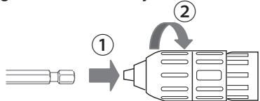
- Attaching Keyless drill chuck
Attach the chuck by sliding the female detent on the bottom of the chuck to the square drive on the body.
Make sure the chuck is firmly connected to the body.
natural_image
Diagram showing a device transforming into a simplified model (no text or symbols)- Inserting the bit
Insert the bit, and turn the lock collar clockwise(looking from the front) holding the sleeve until jaws close firmly.
3. Removing the bit
Turn the lock collar counterclockwise (looking from the front). Then remove the bit.
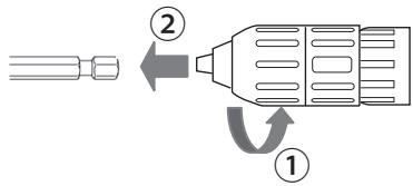
CAUTION: If the drill bit becomes too tight to remove, hold two lock collars with pipe wrenches and turn them inopposite directions.
natural_image
Line drawing of a power tool with two blades and a base, no text or symbols present- Detaching Keyless drill chuck To detach the chuck, PUSH the button to release the chuck from the square drive.
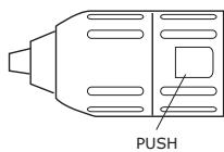
CAUTION: Drill bit blade is sharp. Make sure to remove the drill bit before you set and detach the keyless drill chuck.
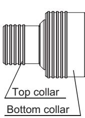
Using Quick change chuck (EY9HX110E)
This Quick change chuck is designed to be used with the square drive of Panasonic impact wrench.
Top collar : To insert or to remove bit
Bottom collar : To attach or to detach Quick change chuck
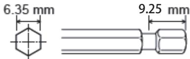
Use 6.35 mm hexagonal bits.
To ensure proper securement of the bit, use only hexagonal bits with 9.25 mm detent.
CAUTION: Make sure the work environment is safe. When retracting bit from work material, Quick change chuck may detach if subjected to 50 kg or more of pull force. Detachment will be sudden. Use care and avoid excessive force when retracting bit from work material.
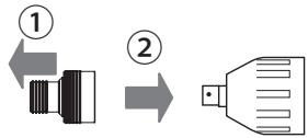
1. Attaching Quick change chuck
Attach the Quick change chuck by pulling the bottom collar forward and sliding the female detent on the bottom of the chuck to the square drive on the body.
Release the bottom collar to make sure the Quick change chuck is firmly connected to the body.
2. Inserting the bit
Pull the top collar of the Quick change chuck forward, then insert the bit.
Release the bottom collar to make sure the bit is firmly connected to the chuck.
- Removing the bit
Pull the top collar of the Quick change chuckforward, then pull the bit.
CAUTION: Impact mechanism creates heat. Square drive and accessory may become very hot and may cause skinburns. To prevent skin burns, use work gloves and/or allow heated parts to cool down before handling.
- Detaching Quick change chuck Pull the bottom collar of the Quick change chuck forward to detach it.
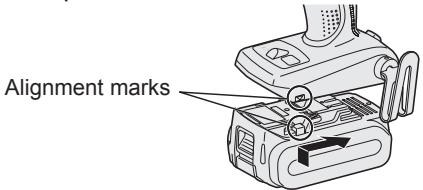
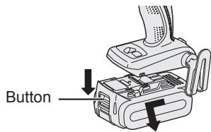
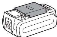
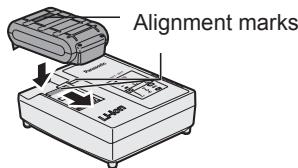
Attaching or Removing Battery Pack
- To connect the battery pack:
Line up the alignment marks and attach the battery pack.
- Slide the battery pack until it locks into position.
- To remove the battery pack:
Pull the button from the front to release the battery pack.
IV. OPERATION
[Main Body]
Switch Operation
- The speed increases with the amount of depression of the trigger. When beginning work, depress the trigger slightly to start the rotation slowly.
- A feedback electronic controller is used to give a strong torque even in low speed.
- The brake operates when the trigger is released and the motor stops immediately.
NOTE:
When the brake operates, a braking sound may be heard. This is normal.
CAUTION:
When operating the tool by pulling the trigger, there may be a momentary lag before rotation starts. This does not signal a malfunction.
* This lag occurs as the tool's circuitry starts up when the trigger is pulled for the first time after installing a new battery pack or after the tool has not been used for at least 1 minute (or at least 5 minutes when the LED is on). Rotation will start without any lag during second and subsequent operations.
Switch and Forward/Reverse Lever Operation
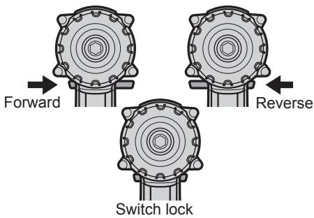
CAUTION:
To prevent damage, do not operate Forward/Reverse lever until the bit comes to a complete stop.
Forward Rotation Switch Operation
- Push the lever for forward rotation.
- Depress the trigger switch slightly to start the tool slowly.
- The speed increases with the amount of depression of the trigger for efficient tightening of screws and drilling. The brake operates and the chuck stops immediately when the trigger is released.
- After use, set the lever to its center position (switch lock).
Reverse Rotation Switch Operation
- Push the lever for reverse rotation. Check the direction of rotation before use.
- Depress the trigger switch slightly to start the tool slowly.
- After use, set the lever to its center position (switch lock).
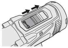
Selecting Mode
| Select mode | Intended use | Work material | Maximum size |
| Impact | Fastening | BoltNut | High tensil:M12Standard :M14 |
| Driving | Wood screwSelf-drilling screw | 9mm 6mm | |
| Drill driverHigh mode | Driving | Wood screwSelf-drilling screw | 4.2mm 6mm |
| Drilling | WoodMetal | 21mm 10mm | |
| Drill driverLow mode | Driving | Wood screw | 6.8mm |
| Drilling | WoodMetal | 35mm 13mm |

WARNING!
This tool must not be used as a drill in "Impact Driver mode". During drilling in steel, the drill bit may break in case of blocking and this may cause dangerous cut wounds.
Impact Driver Operation
Select Impact with the mode select switch.
- Switch to the Impact or Drill driver High/Low position only when the tool has completely stopped rotating. Damage may be caused if the tool is rotating.
natural_image
Technical line drawing of a mechanical device with no visible text or symbolsDrill Driver Operation
Select Drill driver High or Low mode with the mode select switch.
- Switch to the Impact or Drill driver High/Low position only when the tool has completely stopped rotating. Damage may be caused if the tool is rotating.
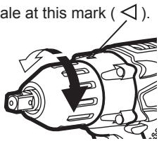
Clutch Torque Setting
Adjust the torque to one of the 21 clutch settings or “ ^2 ” position.
CAUTION:
Test the setting before actual operation.
Set the scale at this mark ( ◀ ).
How to Use the Belt Hook
WARNING!
- Be sure to attach the belt hook securely to the main unit with the screw firmly fastened. When the belt hook is not firmly attached to the main unit, the hook may disconnect and the main unit may fall.
This may result in an accident or injury. - Periodically check screw for tightness. If found to be loose, tighten firmly.
- Be sure to attach the belt hook firmly and securely onto a waist belt or other belt. Pay attention that the unit does not slip off the belt. This may result in an accident or injury.
-
When the main unit is held by the belt hook, avoid jumping or running with it. Doing so may cause the hook to slip and the main unit may fall.
This may result in an accident or injury. -
When the belt hook is not used, be sure to return it to the storing position. The belt hook may catch on something.
This may result in an accident or injury. - When the unit is hooked onto the waist belt by the belt hook, do not attach driver bits to the unit. A sharp edge object, such as a drill bit, may cause injury or an accident.
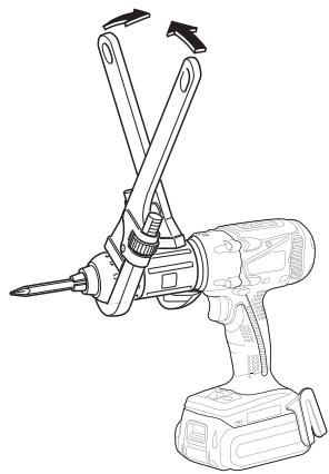
To Change the Belt Hook Location Side
The belt hook can be attached to either side of the unit.
- Removing the hook
(1) Remove the nut.
(2) Draw out the hook.
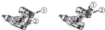
- Attaching the hook to the other side
(1) Insert the hook in the other side.
(2) Tighten the nut fully so that it securely fastened.
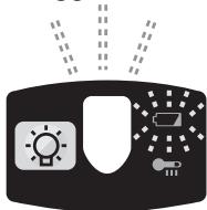
Control Panel
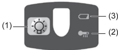
(1) LED light
natural_image
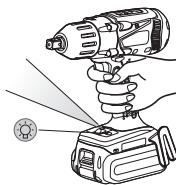
Illustration of a hand using a handheld power tool to lift a battery, with no visible text or symbols.Before the use of LED light, always pull the power switch once.
Press ⚙ the LED light button.
The light illuminates with very low current, and it
does not adversely affect the performance of the tool during use or its battery capacity.
CAUTION:
- The built-in LED light is designed to illuminate the small work area temporarily.
- Do not use it as a substitute for a regular flashlight, since it does not have enough brightness.
- LED light turn off when the tool has not been used for 5 minutes.
Caution : DO NOT STARE INTO BEAM.
Use of controls or adjustments or performance of procedures other than those specified herein may result in hazardous radiation exposure.
(2) Overheat warning lamp

Off
(normal operation)

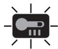
Illuminated: Overheat (motor)
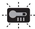
Flashing: Overheat (battery)
Indicates operation has been halted due to motor or battery overheating.
To protect the motor or battery, be sure to note the following when carrying out this operation.
- If the motor or battery becomes hot, the protection function will be activated and the motor or battery will stop operating. The overheat warning lamp on the control panel illuminates or flashes when this feature is active.
- If the overheating protection feature activates, allow the tool to cool thoroughly (at least 30 minutes). The tool is ready for use when the overheat warning lamp goes out.
- Avoid using the tool in a way that causes the overheating protection feature to activate repeatedly.
-
If the tool is operated continuously under high-load conditions or if it is used in hot-temperature conditions (such as during summer), the overheating protection feature may activate frequently.
-
If the tool is used in cold-temperature conditions (such as during winter) or if it is frequently stopped during use, the overheating protection feature may not activate.
- The ambient temperature range is between 0°C (32°F) and 40°C (104°F). If the battery pack is used when the battery temperature is below 0°C (32°F), the tool may fail to function properly.
- When charging a cool battery pack (below 0^ (32^) ) in a warm place, leave the battery pack at the place and wait for more than one hour to warm up the battery to the level of the ambient temperature.
- The performance of the EY9L42 deteriorates significantly at and below 10°C due to work conditions and other factors.
(3) Battery low warning lamp

Off
(normal operation)

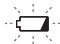
Flashing
(No charge)
Battery protection
feature active
Excessive (complete) discharging of lithium ion batteries shortens their service life dramatically. The driver includes a battery protection feature designed to prevent excessive discharging of the battery pack.
- The battery protection feature activates immediately before the battery loses its charge, causing the battery low warning lamp to flash.
- If you notice the battery low warning lamp flashing, charge the battery pack immediately.
- If it is started with too little battery power remaining, the tool may stop operating without the battery low warning lamp flashing first. This
indicates that there is too little battery power remaining to use the tool, and the battery pack should be charged before further use.
- If the tool is subject to a sudden load during use that causes the motor to lock up, the overdischarge prevention sensor may be triggered, and the battery low warning lamp may flash. The lamp will stop flashing once you address the cause of the motor's locking up and cycle the trigger.
natural_image
Illustration of a device with sun, battery, and plug symbols emitting heat (no text or labels)- The battery protection feature may activate when a high load is abruptly placed on the motor, even if ample battery charge remains. In this case, both the battery low warning lamp and LED light will flash.
- If both the battery low warning lamp and LED light flash, reduce the force with which you are pushing on the driver or, if using a drill driver, adjust the speed switch to a lower setting.
[Battery Pack]
For Appropriate Use of Battery pack
Li-ion Battery pack
- For optimum battery life, store the Li-ion battery pack following use without charging it.
- When charging the battery pack, confirm that the terminals on the battery charger are free of foreign substances such as dust and water etc. Clean the terminals before charging the battery pack if any foreign substances are found on the terminals.
The life of the battery pack terminals may be affected by foreign substances such as dust and water etc. during operation.
- When battery pack is not in use, keep it away from other metal objects like: paper clips, coins, keys, nails, screws, or other small metal objects that can make a connection from one terminal to another.
Shorting the battery terminals together may cause sparks, burns or a fire.
- When operating the battery pack, make sure the work place is well ventilated.
- When the battery pack is removed from the main body of the tool, replace the battery pack cover immediately in order to prevent dust or dirt from contaminating the battery terminals and causing a short circuit.
Battery Pack Life
The rechargeable batteries have a limited life. If the operation time becomes extremely short after recharging, replace the battery pack with a new one.
Battery Recycling
ATTENTION:
For environmental protection and recycling of materials, be sure that it is disposed of at an officially assigned location, if there is one in your country.
[Battery Charger]
Charging
CAUTION:
- If the temperature of the battery pack falls approximately below -10^ (14°F), charging will automatically stop to prevent degradation of the battery.
- The ambient temperature range is between 0^ (32°F) and 40^ (104°F). If the battery pack is used when the battery temperature is below 0^ (32°F), the tool may fail to function properly.
- When charging a cool battery pack (below 0^ (32^) ) in a warm place, leave the battery pack at the place and wait for more than one hour to warm up the battery to the level of the ambient temperature.
- Cool down the charger when charging more than two battery packs consecutively.
- Do not insert your fingers into contact hole, when holding charger or any other occasions.
To prevent the risk of fire or damage to the battery charger.
- Do not use power source from an engine generator.
- Do not cover vent holes on the charger and the battery pack.
- Unplug the charger when not in use.
NOTE:
Your battery pack is not fully charged at the time of purchase. Be sure to charge the battery before use.
Battery charger
- Plug the charger into the AC outlet.
-
Insert the battery pack firmly into the charger.
-
Line up the alignment marks and place the battery onto the dock on the charger.
- Slide forward in the direction of the arrow.
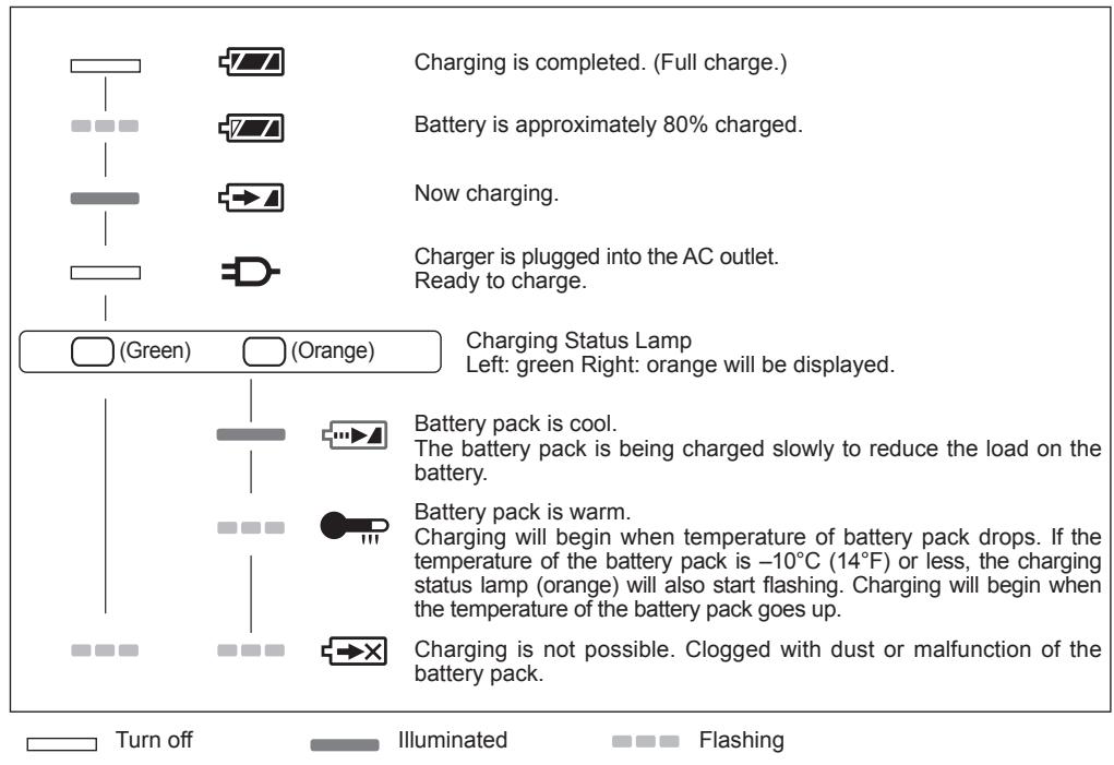
- During charging, the charging lamp will be illuminated.
When charging is completed, an internal electronic switch will automatically be triggered to prevent overcharging.
- Charging will not start if the battery pack is warm (for example, immediately after heavy-duty operation). The orange standby lamp will be flashing until the battery cools down. Charging will then begin automatically.
- The charge lamp (green) will flash slowly once when the battery is approximately 80% charged.
- When charging is completed, the charging lamp in green color will turn off.
- If the temperature of the battery pack is 0^ C or less, charging takes longer to fully charge the battery pack than the standard charging time.
Even when the battery is fully charged, it will have approximately 50% of the power of a fully charged battery at normal operating temperature.
- Consult an authorized dealer if the charging lamp (green) does not turn off.
- If a fully charged battery pack is inserted into the charger again, the charging lamp lights up. After several minutes, the charging lamp in green color will turn off.
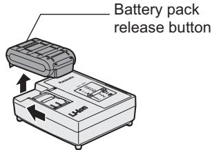
- Remove the battery pack while the battery pack release button is held up.
LAMP INDICATIONS
Information for Users on Collection and Disposal of Old Equipment and used Batteries
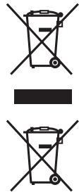
These symbols on the products, packaging, and/or accompanying documents mean that used electrical and electronic products and batteries should not be mixed with general household waste.
For proper treatment, recovery and recycling of old products and used batteries, please take them to applicable collection points, in accordance with your national legislation and the Directives 2002/96/EC and 2006/66/EC.
By disposing of these products and batteries correctly, you will help to save valuable resources and prevent any potential negative effects on human health and the environment which could otherwise arise from inappropriate waste handling.
For more information about collection and recycling of old products and batteries, please contact your local municipality, your waste disposal service or the point of sale where you purchased the items.
Penalties may be applicable for incorrect disposal of this waste, in accordance with national legislation.
For business users in the European Union
If you wish to discard electrical and electronic equipment, please contact your dealer or supplier for further information.
V. ACCESSORIES
Use only bits suitable for size of drill's chuck.
Use Panasonic original Optional Keyless drill chuck (EY9X003E) and Quick change chuck(EY9HX110E) for maximum performance.
VI. MAXIMUM RECOMMENDED CAPACITIES
| Screw driving | Wood screw | Impact modeDrill driver High modeDrill driver Low mode | 9 mm 4,2 mm 6,8 mm |
| Self-drilling screw | Impact modeDrill driver High mode | 6 mm 6 mm | |
| Bolt fastening | Impact mode | Standard bolt :M14High tensile bolt :M12 | |
| Drill | Steel | Drill driver High modeDrill driver Low mode | 10 mm 13 mm |
| Wood | Drill driver High modeDrill driver Low mode | 21 mm 35 mm | |
VII. SPECIFICATIONS
MAIN UNIT
| Model | EY7549 |
| Motor | 14.4 V DC |
| No load speed | Impact mode: 0 – 2300 min ^-1 |
| Drill driver High mode:0-1200min ^-1 | |
| Drill driver Low mode:0-380min ^-1 | |
| Maximum torque | Impact mode: 150 N•m with M16 High tensile bolt130 N•m with M14 High tensile bolt |
| Drill driver High mode:9 N•m | |
| Drill driver Low mode:26 N•m | |
| Clutch torque | Approx. 0.7 - 4.4 N•m |
| Overall length | 210 mm |
| Weight (with battery pack) | 1.85 kg |
| Noise vibration | See the included sheet |
BATTERY PACK
| Model No. | EY9L41 | EY9L42 | EY9L44 | EY9L45 |
| Storage battery | Li-ion Battery | |||
| Motor voltage | 14.4 V DC (3.6 V × 4 cells) | 14.4 V DC (3.6 V × 8 cells) | ||
BATTERY CHARGER
| Model No. | EY0L81 | |||
| Electrical rating | See the rating plate on the bottom of the charger | |||
| Weight | 0.93 kg | |||
| Charging time | EY9L41 | EY9L42 | EY9L44 | EY9L45 |
| Usable: 45 min. | Usable: 30 min. | Usable: 50 min. | Usable: 65 min. | |
| Full: 60 min. | Full: 35 min. | Full: 65 min. | Full: 80 min. | |
| Model No. | EY0L82 | |||
| Electrical rating | See the rating plate on the bottom of the charger | |||
| Weight | 0.93 kg | |||
| Charging time | EY9L41 | EY9L42 | EY9L44 | EY9L45 |
| Usable:35min | Usable:30min | Usable:40min | Usable:50min | |
| Full:50min | Full:35min | Full:55min | Full:60min | |
NOTE: This chart may include models that are not available in your area.
Please refer to the latest general catalogue.
NOTE: For the dealer name and address, please see the included warranty card.
ONLY FOR U. K.
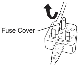
X. ELECTRICAL PLUG INFORMATION
FOR YOUR SAFETY PLEASE READ THE FOLLOWING TEXT CAREFULLY
This appliance is supplied with a moulded three pin mains plug for your safety and convenience.
A 5 amp fuse is fitted in this plug.
Should the fuse need to be replaced please ensure that the replacement fuse has a rating of 5 amp and that it is approved by ASTA or BSI to BS1362.
Check for the ASTA mark ◆ or the BSI mark ♥ on the body of the fuse.
If the plug contains a removable fuse cover you must ensure that it is refitted when the fuse is replaced.
If you lose the fuse cover the plug must not be used until a replacement cover is obtained.
A replacement fuse cover can be purchased from your local Panasonic Dealer.
IF THE FITTED MOULDED PLUG IS UNSUITABLE FOR THE SOCKET OUTLET IN YOUR HOME THEN THE FUSE SHOULD BE REMOVED AND THE PLUG CUT OFF AND DISPOSED OF SAFELY.
THERE IS A DANGER OF SEVERE ELECTRICAL SHOCK IF THE CUT OFF PLUG IS INSERTED INTO ANY 13 AMP SOCKET.
If a new plug is to be fitted please observe the wiring code as shown below.
If in any doubt please consult a qualified electrician.
IMPORTANT:
The wires in this mains lead are coloured in accordance with the following code:
Blue: Neutral
Brown: Live
As the colours of the wire in the mains lead of this appliance may not correspond with the coloured markings identifying the terminals in your plug, proceed as follows.
The wire which is coloured BLUE must be connected to the terminal in the plug which is marked with the letter N or coloured BLACK.
The wire which is coloured BROWN must be connected to the terminal in the plug which is marked with the letter L or coloured RED.
Under no circumstances should either of these wires be connected to the earth terminal of the three pin plug, marked with the letter E or the Earth Symbol 12 .
How to replace the fuse: Open the fuse compartment with a screwdriver and replace the fuse and fuse cover if it is removable.
This apparatus was produced to BS800.
natural_image
Diagram showing a drill bit transforming into a drill cap (no text or symbols)natural_image
Line drawing of a power tool with two blades and a base, no text or symbols presentnatural_image
Technical line drawing of a mechanical device with a knob and handle (no text or symbols)natural_image
Technical line drawing of a mechanical component with arrows indicating motion or assembly (no text or symbols)natural_image
Technical line drawing of a mechanical component with no visible text or symbolsnatural_image
Diagram of a mechanical component with directional arrows indicating motion or force (no text or symbols)natural_image
Illustration of a hand holding a handheld power tool with a targeting device (no text or symbols)natural_image
Illustration of a device with a light bulb, sensor, and control buttons (no text or symbols)natural_image
Diagram showing a device transitioning from a rectangular block to a rectangular component with a dot (no text or symbols)- Insertion du foret
natural_image
Line drawing of a power tool with dual blades and a base (no text or symbols)natural_image
Line drawing of a handheld electronic device with a scroll wheel and directional arrow (no text or symbols)natural_image
Technical line drawing of a mechanical component with internal components and directional arrows (no text or symbols)natural_image
Technical line drawing of a mechanical component with no visible text or symbolsnatural_image
Mechanical diagram showing a rotating component with a black arrow indicating direction (no text or symbols)natural_image
Illustration of a hand using a handheld power tool to lift a battery, with no visible text or symbols.natural_image
Illustration of a device with a light bulb, sensor, and control buttons (no text or symbols)natural_image
Diagram showing a device transitioning from a rectangular block to a cylindrical component with internal structure (no text or symbols)ATTENZIONE :
natural_image
Line drawing of a power tool with two blades and a base, showing mechanical assembly (no text or symbols)natural_image
Line drawing of a handheld electronic device with a scroll wheel and mechanical components (no text or symbols)natural_image
Technical line drawing of a mechanical component with internal components and directional arrows (no text or symbols)natural_image
Technical line drawing of a mechanical component with no visible text or symbolsnatural_image
Diagram of a mechanical component with a directional arrow indicating motion (no text or symbols)natural_image
Illustration of a hand using a handheld power tool to lift a battery, with no visible text or symbols.natural_image
Illustration of a black electronic device with a light bulb, switch, and power button (no text or symbols)natural_image
Diagram showing a device transitioning from a rectangular block to a cylindrical component with internal structure (no text or symbols)- Insteken van de bit
natural_image
Line drawing of a handheld electric drill with two blades and a base (no text or symbols)natural_image
Technical line drawing of a mechanical component with arrows indicating motion or assembly (no text or symbols)natural_image
Technical line drawing of a mechanical component with no visible text or symbolsSchroefboormachine Hoog-modus
natural_image
Mechanical diagram showing a rotating component with an arrow indicating direction (no text or symbols)natural_image
Illustration of a hand using a handheld power tool on a battery, with no visible text or symbols.Oververhitting (motor)
Knippert:
Oververhitting (accu)
natural_image
Illustration of a device with sun, battery, and sensor symbols (no text or labels)natural_image
Diagram of a device with an open lid and internal components, showing directional arrows (no text or symbols)natural_image
Diagram showing a device transitioning from a rectangular panel to a cylindrical component with internal structure (no text or symbols)- Inserción de la broca
natural_image
Line drawing of a handheld electric drill with two blades and a base (no text or symbols)natural_image
Technical line drawing of a mechanical component with arrows indicating direction (no text or symbols)natural_image
Technical line drawing of a mechanical component with two arrows indicating motion or assembly (no text or symbols)Modo Taladro atornillador alto
natural_image
Mechanical assembly diagram showing a rotating component with a downward arrow indicating motion (no text or symbols)natural_image
Illustration of a hand using a handheld power tool to lift a battery, with no visible text or symbols.natural_image
Illustration of a black device with a light bulb, battery, and warning symbol emitting heat (no text or labels)natural_image
Diagram showing a device transitioning from a rectangular panel to a cylindrical component, with no text or symbols present.- Isætning af bit
natural_image
Line drawing of a handheld electric drill with two blades and a base (no text or symbols)- Indsætning af bit
natural_image
Technical line drawing of a mechanical component with arrows indicating direction (no text or symbols)Bore/Skrue Høj
natural_image
Illustration of a hand using a handheld power tool to lift a battery, with no visible text or symbols.natural_image
Illustration of a black electronic device with a light bulb, battery, and indicator lights (no text or symbols)natural_image
Diagram showing a device transforming into a simplified model (no text or symbols)natural_image
Line drawing of a power tool with two blades and a base, showing mechanical assembly (no text or symbols)natural_image
Technical line drawing of a mechanical component with two arrows indicating direction (no text or symbols)natural_image
Mechanical assembly diagram showing a rotating component with a downward arrow indicating motion (no text or symbols)natural_image
Illustration of a hand holding a drill bit connected to a battery, with no visible text or symbols.natural_image
Illustration of a device with a light bulb, battery, and sensor array (no text or symbols)natural_image
Diagram showing a device transforming into a simplified model (no text or symbols)- Montere bitset
- Demontere bitset
Drei låseringen moturs (sett forfra). Demonter bitset.

natural_image
Line drawing of a power tool with two blades and a base, showing mechanical assembly (no text or symbols)- Montere bitset
natural_image
Line drawing of a handheld electronic device with a scroll wheel and control panel (no text or symbols)natural_image
Technical line drawing of a mechanical component with arrows indicating motion or assembly (no text or symbols)Betjening som bormaskin skrutrekker
natural_image
Mechanical component diagram showing a rotating shaft and housing with directional arrows (no text or symbols)natural_image
Illustration of a hand holding a handheld power drill press with a battery and a rotary knob (no text or symbols)Før bruk av LED-lys, skru alltid av strømbryteren en gang.
Trykk på LED-lysknappen
(2) Varsellampe for overoppheting

Av
(normalt arbeid)

Lyser:
Overoppheting (motor)
Blinker:
Overoppheting (batteri)
natural_image
Illustration of a device with sun, battery, and sensor symbols (no text or labels)natural_image
Diagram showing a device transforming into a simplified model (no text or symbols)3. Terän irrotus
natural_image
Line drawing of a handheld electric drill putter with two blades and a base (no text or symbols)flowchart
graph LR
    A["Step 1: Leftward arrow"] --> B["Step 2: Rightward arrow"]
    B --> C["Final connector"]
- Terän asettaminen
natural_image
Line drawing of a handheld electronic device with a scroll wheel and control panel (no text or symbols)- Akun irrottaminen:
natural_image
Technical line drawing of a mechanical component with arrows indicating motion or flow direction (no text or symbols)natural_image
Mechanical diagram showing a gear or motor assembly with a downward arrow indicating motion (no text or symbols present)Vyölenkin käyttö
⚠️ VAROITUS!
natural_image
Illustration of a hand using a handheld power tool to lift a battery (no text or symbols visible)natural_image
Illustration of a device with a light bulb, sensor array, and indicator lights (no text or symbols)Panasonic Testing Center
Winsbergring 15,
22525 Hamburg,
Germany
Panasonic Corporation
1006,Kadoma,Osaka 571-8501,Japan
http://panasonic.net