
ESM200 - Measurement OREGON SCIENTIFIC - Free user manual and instructions
Find the device manual for free ESM200 OREGON SCIENTIFIC in PDF.


| Product type | Digital weather station |
| Brand | Oregon Scientific |
| Model | ESM200 |
| Dimensions | 120 x 100 x 30 mm |
| Weight | 200 g (with batteries) |
| Power supply | 2 AAA batteries (1.5 V) |
| Display | Backlit LCD |
| Main functions | Indoor and outdoor temperature, humidity, weather forecast, clock, alarm, calendar |
| Outdoor sensor range | Up to 30 m in open field |
| Outdoor sensor | Wireless, 1 sensor included (thermo-hygrometer) |
| Radio frequency | 433 MHz |
| Temperature measurement range | -20°C to +60°C (indoor/outdoor) |
| Humidity measurement range | 25% to 95% RH |
| Temperature accuracy | ±1°C |
| Humidity accuracy | ±5% RH |
| Memory function | Min/Max value recording |
| Alarm | Built-in buzzer and vibrator |
| Backlight | Yes, activated by button |
| Protection rating | IPX4 (outdoor sensor) |
| Care and cleaning | Clean with a soft, dry cloth. Do not use solvents. |
| Safety | Keep batteries out of reach of children. Do not expose the device to water or extreme temperatures. |
| Spare parts / repairability | Batteries, outdoor sensor (reference THN132N). Parts available on the Oregon Scientific website. |
| General information | Measuring device for domestic use. Weather forecast consultation for 12 to 24 hours. |
Frequently Asked Questions - ESM200 OREGON SCIENTIFIC
User questions about ESM200 OREGON SCIENTIFIC
0 question about this device. Answer the ones you know or ask your own.
Ask a new question about this device
Download the instructions for your Measurement in PDF format for free! Find your manual ESM200 - OREGON SCIENTIFIC and take your electronic device back in hand. On this page are published all the documents necessary for the use of your device. ESM200 by OREGON SCIENTIFIC.
USER MANUAL ESM200 OREGON SCIENTIFIC
Wireless Energy Manager Model: ESM200 / ESM200U
User Manual
Wireless Energy Manager
Model: ESM200 / ESM200UESM200
USER MANUAL
CONTENTS
Introduction ...... 2
Overview 2
Main unit – front view 2
Main unit - back view 3
Remote transmitter 4
Sensor Clamp 4
Household power cables and phase 5
Getting started 5
Locate live outgoing supply cable 5
Sensor set up 5
Transmitter set up 6
Main unit set up 7
Sensor data transmission 7
Understanding electricity 7
Display modes 8
Setting mode - General 8
Set country 9
Cost rate 10
Clock and calendar 10
Clear records ....11
Reset 11
ESM200U Nobleshooting ....11
Specifications 12
Precautions 12
About Oregon Scientific 13
EU-Declaration of conformity 13
INTRODUCTION
Thank you for selecting the Oregon Scientific™ Wireless Energy Manager (ESM200 / ESM200U).
The Wireless Energy Manager embodies our commitment to environmental concerns. Aware of threats facing the world we live in, Oregon Scientific™ has combined technological know-how, practicality and style to create this line of products that can help you reduce your carbon footprint.
With this measurement category II product, you can view your consumption in real time. By being made aware of your consumption, you can take practical steps to reduce it. Your continued effort will be reflected by the monitor in meaningful terms - estimated costs / consumption go down over time.
Our aim is to make products that provide practical solutions while enabling you and us to fulfill our environmental responsibility. Together we can improve the world we live in.

Please observe the following warning and safety caution guidelines when setting up and using this act.
NOTE Please keep this manual handy as you use your new product. It contains practical step-by-step instructions, as well as technical specifications and warnings you should know about.
If the equipment is used in a manner not specified in this manual, the protection provided by the equipment may be impaired.
OVERVIEW
MAIN UNIT - FRONT VIEW

- ENERGY: indicates energy consumption is displayed
- COST: indicates cost of energy consumed is displayed
- ⑤ indicates unit is in Setting mode
- User selectable currency units - F / P / R / Kr / £ / \$ / € / ¥
- Weekday
- Clock / calendar
- Indicates electricity used now will be charged at peak time rates
- :IADuates at which rate electricity is charged
- MODE: toggle between different displays; activate / deactivate alarm; navigate through sub-setting options
- SEARCH: initiate remote transmitter search
- GREENHOUSE GAS: indicates greenhouse gas emission as per energy consumption
- Real time cost / energy consumption / greenhouse gas emission caused
- Cost / energy consumption / greenhouse gas measurement units
- Indicates which accumulative / historical data is displayed
- Accumulative / historical cost / energy consumption / greenhouse gas emission
- Cost / energy consumption / greenhouse gas measurement units
- Temperature
- Indicates cost alarm is ON
- REMOTE MAIN remote transmitter batteries low / main unit batteries low
- CH123: channel indicator
- SET: enter setting mode; confirm settings
- ADJUST: toggle between different historical displays; change setting values / item
MAIN UNIT - BACK VIEW
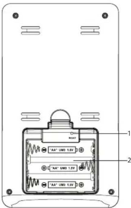
- RESET: resets the unit; initiate remote transmitter search
- Battery compartment
REMOTE TRANSMITTER

- LED status indicator: flashes when searching
- Sensor cable sockets
- Wall mount hole
- Battery compartment
- RESET: resets the unit to default settings
- CHECK: forces transmission every 2 seconds (for a period of 30 seconds) to attempt link with main unit
- CHANNEL switch
SENSOR CLAMP
| Model CT100(Europe / UK) | Model CT110(USA, Canada & other countries) |
| Sensor for :• 220V to 250V AC• cable size up to 10mm dia &/or 70 amps RMS) | Sensor for:• 120V AC + Industry• cable size up to 16mm dia &/or 200 amps RMS) |
 | 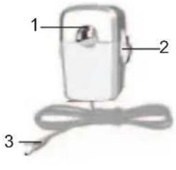 |
- Electrical wire hole Electrical wire hole
- Plastic tabsPlastic tabs
- Sensor transmitter cable
Optional sensor clamps such as those listed below can be purchased separately. For more information, please contact your local retailer.
- Model CT100
- Model CT110
* Features and accessories will not be available in all countries.
HOUSEHOLD POWER CABLES AND PHASE
Electricity is generally supplied using single-phase and three-phase systems.
UK: Most homes in the UK use single-phase supplies. In single-phase supplies, the current flows to and from your household appliances using a neutral and live wire. The neutral wire has a voltage close to zero while the live wire carries a voltage from 120 to 240 volts. The difference between these two wires makes the current flow through your appliances.
Europe: Most homes in Europe use three-phase supplies. In three-phase supplies, current flows to and from a device through a group of three wires - each one carrying a fluctuating phase. The three wires, therefore, each need an individual current sensor which can be purchased separately.
GETTING STARTED
LOCATE LIVE OUTGOING SUPPLY CABLE
The sensor clamp should be fitted over the insulated live wire. It is recommended that you fit it over the (outgoing) wire which comes out of the electricity meter located in the meter box.
This product uses Type C current sensor, do not apply around or remove from HAZARDOUS LIVE conductors. Under no circumstances should any force or undue pressure be applied to any wiring or connections.
WARNING Care must be taken at all times to avoid touching or coming into contact with any un-insulated wires or contacts. If any difficulty with installation is experienced at all, the advice of a licensed electrician should be sought.

SENSOR SET UP
WARNING It is recommended for current sensor clamp(s) to be installed by a licensed electrician. Switch off power from the mains before attaching and detaching sensor(s).
-
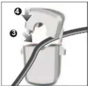
Using thumb and finger, press inwards on plastic tabs located on either side of the sensor clamp to release top part.
-
Lift the top of the sensor away.

- Place the main household active or live wire (outgoing) into the electrical wire hole.
NOTE Do not pull or bend the wires. Ease the wire into position so you can close the sensor clamp securely around the wire.
4. Replace the top of the sensor clamp and push down to secure.
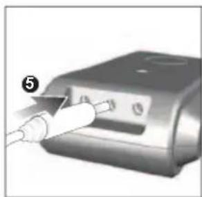
5. Plug the sensor transmitter cable into any of the cable sockets.

natural_image
Close-up of a medical device with a probe inserted into a device (no visible text or symbols)NOTE For three-phase system, attach a sensor clamp to each live wire.
- When attaching the sensor clamp, ensure each sensor clamp is attached to a different wire otherwise an incorrect reading may result.
- Then plug all sensor clamp cables into the remote transmitter. Up to three sensor clamps can be plugged into the remote transmitter.

WARNING
- The signal wiring (approx. 1 volt, 1 milliamp) on the sensor clamp is double insulated, suitable for installation in domestic power supply meter box. When passing through an enclosure opening, the wiring should be protected from sharp edges by fixed bushes.
- Do not use the unit if it is damaged or its safety is impaired.
TRANSMITTER SET UP
- Slide open the battery compartment cover.
- Slide channel switch to 2 (default).
- Insert the batteries, matching the polarities (+ / -).
- Press RESET after each battery change.
- Press and hold CHECK until LED light flashes.
- Close the battery door.
- Mount the transmitter onto an affixed screw.

natural_image
Illustration of a door switch with an arrow pointing right, next to a vertical line (no text or symbols)NOTE Install battery in the transmitter before the main unit.
For best results:
- Place the sensor within 30 m (100 ft) of the main unit.
- Place the sensor out of direct sunlight and moisture.
- Position the sensor so that it faces the main (indoor) unit, minimizing obstructions such as doors, walls and furniture.
TIP The transmission range may vary depending on many factors. You may need to experiment with various locations to get the best results.
MAIN UNIT SET UP
- Slide open the battery compartment cover.
- Insert the batteries, matching the polarities (+ / -).
- Press RESET after each battery change.
- Close the battery door.
SENSOR DATA TRANSMISSION
If main unit does not display data or after each transmitter battery change:
- Press and hold CHECK (located in the transmitter) until LED light flashes. Transmitter will check for and transmit data to the main unit every 2 seconds for 30 seconds.
- Press and hold SEARCH on the main unit to search signal from transmitter.
The main unit may display incorrect readings or no readings, possibly due to receiving data from a nearby sensor. Though it is recommended to use channel 2 (default), user can manually choose another channel (1 or 3) to attempt another link up. If a channel, other than 2 has been selected on the sensor, main unit settings must also be updated (See "SET COUNTRY" section in this manual for instructions).
UNDERSTANDING ELECTRICITY
| Voltage (volts) | Electrical potential. Fixed at 220V-250V or 120V depending on region. |
| X | |
| Current (amps) | Amount of electricity flowing through, e.g., a wire. (The sensor measures this to determine watt) |
| = | |
| Power (watts) | Amount of energy being transferred. (KW = 1000W). This type of data is displayed on the top line of Energy mode. |
KWh is a measure of consumption. Kilowatt hour represents the use of 1000W of electricity for 1 whole hour, which is equivalent to ten x 100W light bulbs operating at the same time for 1 hour.
Once cost rate of electricity has been inputted, the monitor can arrive at an estimated cost. Each utility company sets a different tariff for electricity consumption. This rate can usually be found on the electricity bill.
Fossil fuel power stations produce greenhouse gasses as a by-product of the production process. These gasses have been linked to climate change. The amount of greenhouse gas emitted is different for each utility company. For your convenience, a default greenhouse emission rate (per 1KWh of electricity produced) has been set on this unit. However, this rate can be changed if desired.
NOTE This product is for educational purposes only. Its aim is to aid understanding of the cost of operating electrical appliances in the home. It does not replace your accurate electricity revenue meter.
DISPLAY MODES
There are 3 display modes to choose from:
| COST |  | Real time cost of electricity per hourAccumulated cost since last reset |
| ENERGY |  | Real time power (KW)Accumulated energy (KWh) consumed since last reset |
| GREEN-HOUSE GAS | 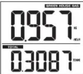 | Current green house gas emitted per hourAccumulated green house gas emitted since last reset |
To toggle between displays:
- Press MODE.
To view accumulated cost / energy / greenhouse gas for different periods:
- Press ADJUST.
SETTING MODE - GENERAL
To navigate the Setting mode:
SET – enters setting mode / sub settings; confirms setting
MODE – toggles between settings / options
ADJUST – changes setting values
IMPORTANT Please choose currency for country you reside in prior to use as the unit cannot calculate exchange rates for currencies, i.e., convert £ to €.

flowchart
graph TD
    A["COST"] --> B["MODE"]
    B --> C["TIME"]
    C --> D["MODE"]
    D --> E["DATE"]
    E --> F["MODE"]
    F --> G["ACCU"]
    G --> H["MODE"]
    H --> I["OTHER"]
    I --> J["MODE"]
    J --> K["END"]
SET COUNTRY
TIP Country related settings, e.g., value of VOLT and measurement units of CURR, UNIT, TEMP will change automatically according to the country chosen.
- Press and hold SET to enter Setting mode.
- Press MODE repeatedly to navigate to sub setting OTHER. Press SET to enter.
- Press MODE repeatedly to navigate to CNTY. Press SET to enter.
- Press ADJUST to change setting. Press SET to confirm and move to next setting option.
OTHER menu options are:
| OPTIONS SELECTABLE VALUES | |
| CNTY AUS / EUR / NZ / UK / SA | |
| CURR F / P / R / Kr / £ / $ / € / ¥ | |
| VOLT 110 / 120 / 220 / 230 / 240 / 250 | |
| UNIT* KG.KG / LB.LB / TONN / TON | |
| TEMP °C / °F | |
| CHAN 1 / 2 / 3 | |
| GHG | 0.00-1.90 (KG / KWH)0.00 – 4.19 (LB / KWH) |
To exit Setting mode:
- Press MODE repeatedly to navigate to END.
- Press SET to select and return to COST display.
After 1 minute of inaction, unit will return to COST display automatically.
\* Alternative method to change units:
- While in normal display, press MODE repeatedly to enter GREENHOUSE GAS display.
- Press and hold ADJUST repeatedly to change measurement unit.
COST RATE
To determine the approximate cost of electricity consumption, input the cost per KWh.
This unit allows the input of up to 4 different cost rates (Tariff) to accommodate the different rates local utility companies may charge consumers depending on the hour electricity is consumed.
The PICOITIM will be displayed to remind users that electricity used during that period will be charged at peak rates.
There is also a built-in alarm to alert users when the electricity cost per hour exceeds a pre-set limit.
By raising awareness of consumption behaviour, better consumption habits may be adopted which will in turn reduce the cost of electricity bills and impact on the environment.
To set cost rate:
- Press and hold SET to enter Setting mode.
- Press MODE repeatedly to navigate to sub setting COST. Press SET to enter.
- Press SET to enter TAR 1 setting.
- Press SET to enter TIME setting.
- Press ADJUST to change setting values.
- Press SET to confirm and move to next setting. The setting options are hour, minutes, rate, peak (yes / no) and alarm (on / off).
NOTE If there is only one electricity rate for the entire duration of the day, select OFF for TAR 2-4.
For other TAR 2-4 settings:
- Press SET to enter TAR 2 setting.
- Press ADJUST to select ON.
- Repeat steps 4-6 above.
To exit Setting mode:
- Press MODE repeatedly to navigate to END.
- Press SET to exit and return to COST display.
If originally on upper line of display, repeat steps 1-2 to exit completely.
Alternative method to enable /disable alarm:
- Press and hold MODE (when not in setting mode).
CLOCK AND CALENDAR
- Press and hold SET to enter Setting mode.
- Press MODE repeatedly to navigate to sub setting TIME. Press SET to enter.
- Press ADJUST to change setting values.
- Press SET to confirm and move to next setting. The setting options are hour format, hour, minutes.
- Press SET to enter DATE menu options.
- Press ADJUST to change setting values.
- Press SET to confirm and move to next setting. The setting options are date format, year, month, day.
- Press MODE repeatedly to navigate to END. Press SET to exit and return to COST display.
CLEAR RECORDS
To clear records of TOTAL data (Cost / Energy / GHG):
- Press and hold SET to enter Setting mode.
- Press MODE repeatedly to navigate to sub setting ACCU. Press SET to enter.
- Press ADJUST to select RESET YES / NO.
- Press SET to confirm.
- Press MODE repeatedly to navigate to END. Press SET to exit and return to COST display.
OR
- Press and hold MODE and SET simultaneously (when not in Setting mode).
Key tone confirms delete process is complete and successful.
To clear all memory in main unit and return to default settings:
- Press and hold SET and RESET together.
RESET
Press RESET to restart the unit, main unit will search for last transmitter received.
NOTE Records of Total data (accumulated cost / energy / greenhouse gas) is stored in memory.
TROUBLESHOOTING
| PROBLEM SYMPTOM REMEDY | ||
| Strange readings | Strange readings | Set cost rate setting. |
| Check appliances are not malfunctioning (turned off by itself) as this could be shown as a sudden drop in electricity usage. | ||
| High readings | Check appliances have been switched off if not in use. | |
| “- - - ” displayed | Not synchronised | Press and hold CHECK on remote transmitter. Then, press and hold SEARCH on the main unit. If still unsuccessful, press RESET on transmitter and main unit. |
| “0.00” displayed | Problem with the sensor | Check sensor clamp has been properly fitted and closed. |
| Possible damage in the sensor clamp. Replace clamp with new one. | ||
SPECIFICATIONS
MAIN UNIT
| Dimensions(L x W x H) | 93 x 47 x 163 mm(3.6 x 1.9 x 6.4 inches) |
| Weight 182 g (6.4 oz) without battery | |
| Signal frequency 433 MHz | |
| Transmission range | 30 meters (100 feet) unobstructed |
| Information update | Approximately every 6 seconds (EU) / 12 seconds (US / Canada) |
| Power 3 x UM-3 (AA) 1.5V batteries | |
REMOTE TRANSMITTER
| Dimensions(L x W x H) | 59 x 28 x 97 mm(2.3 x 1.1 x 3.8 inches) |
| Weight 60 g (2.1 oz) without battery | |
| Power 2 x UM-3 (AA) 1.5V batteries | |
SENSOR CLAMP
| CT100 | |
| Dimensions(L x W x H) | 40 x 30 x 54 mm(1.6 x 1.2 x 2.1 inches) |
| Weight 62 g (2.2 oz) | |
| CT110 | |
| Dimensions(L x W x H) | 53 x 40 x 76 mm(2.1 x 1.6 x 3.0 inches) |
| Weight 186 g (6.6 oz) | |
PRECAUTIONS
- Do not subject the unit to excessive force, shock, dust, temperature or humidity.
- Do not cover the ventilation holes with any items such as newspapers, curtains etc.
- Do not immerse the unit in water. If you spill liquid over it, dry it immediately with a soft, lint-free cloth.
- Do not clean the unit with abrasive or corrosive materials.
- Do not tamper with the unit's internal components. This invalidates the warranty.
- Only use fresh batteries. Do not mix new and old batteries.
- Images shown in this manual may differ from the actual display.
- When disposing of this product, ensure it is collected separately for special treatment and not as normal household waste.
- Placement of this product on certain types of wood may result in damage to its finish for which Oregon Scientific will not be responsible. Consult the furniture manufacturer's care instructions for information.
- The contents of this manual may not be reproduced without the permission of the manufacturer.
- Do not dispose old batteries as unsorted municipal waste. Collection of such waste separately for special treatment is necessary.
- Please note that some units are equipped with a battery safety strip. Remove the strip from the battery compartment before first use.
NOTE The technical specifications for this product and the contents of the user manual are subject to change without notice.
NOTE Features and accessories will not be available in all countries. For more information, please contact your local retailer.
ABOUT OREGON SCIENTIFIC
Visit our website (www.oregonscientific.com) to learn more about Oregon Scientific products. If you're in the US and would like to contact our Customer Care department directly, please visit: www2.oregonscientific.com/service/support.asp
For international inquiries, please visit: www2.oregonscientific.com/about/international.asp
EU-DECLARATION OF CONFORMITY
Hereby, Oregon Scientific, declares that this Wireless Energy Manager (model: ESM200 / ESM200U) is in compliance with the essential requirements and other relevant provisions of Directive 1999/5/EC. A copy of the signed and dated Declaration of Conformity is available on request via our Oregon Scientific Customer Service.


COUNTRIES RTTE APPROVED COMPLIED
All EU countries, Switzerland
and Norway
CH
N

natural_image
Close-up of a USB flash drive with a cable inserted, showing ports and an icon (no text or symbols)natural_image
3D rendering of a door with an arrow symbol, next to a vertical line (no text or labels)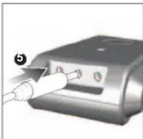
natural_image
Close-up of a medical device with a probe inserted, showing ports and a label (no readable text or symbols)natural_image
Illustration of a mobile phone with a right-pointing arrow (no text or symbols)EUROPE – DÉCLARATION DE CONFORMITÉ
natural_image
Close-up of a device with a cable inserted into a slot, labeled with number 5 (no text or symbols on the device itself)natural_image
3D rendering of a mobile phone with an arrow pointing right, next to a vertical line (no text or symbols)www2.oregonscientific.com/about/international.asp

natural_image
Close-up of a device with a white cable inserted into a button (no visible text or symbols)natural_image
Illustration of a door switch with an arrow pointing right, next to a vertical line (no text or symbols)Transmissor remoto 4
Braçadeiras do sensor 4

natural_image
Close-up of a USB flash drive with a probe inserted, no visible text or symbolsnatural_image
3D illustration of a door lock with an arrow symbol, no text or labels presentAPPARAAT - ACHTERKANT

natural_image
Illustration of a mobile phone with an arrow symbol on the door (no text or labels)
natural_image
Close-up of a device with a probe inserted into a component, labeled with number 5 (no text or symbols on the device itself)natural_image
Illustration of a mobile phone with a right-pointing arrow (no text or symbols)© 2010 Oregon Scientific. All rights reserved.
300102472-00001-10
- Wireless Energy Manager
- Model: ESM200 / ESM200UESM200
- USER MANUAL
- CONTENTS
- INTRODUCTION
- OVERVIEW
- REMOTE TRANSMITTER
- SENSOR CLAMP
- HOUSEHOLD POWER CABLES AND PHASE
- GETTING STARTED
- LOCATE LIVE OUTGOING SUPPLY CABLE
- SENSOR SET UP
- WARNING
- TRANSMITTER SET UP
- For best results:
- MAIN UNIT SET UP
- SENSOR DATA TRANSMISSION
- If main unit does not display data or after each transmitter battery change:
- DISPLAY MODES
- SETTING MODE - GENERAL
- SET COUNTRY
- To exit Setting mode:
- \* Alternative method to change units:
- COST RATE
- To set cost rate:
- For other TAR 2-4 settings:
- Alternative method to enable /disable alarm:
- CLOCK AND CALENDAR
- CLEAR RECORDS
- RESET
- PRECAUTIONS
- ABOUT OREGON SCIENTIFIC
- EU-DECLARATION OF CONFORMITY
- COUNTRIES RTTE APPROVED COMPLIED
- EUROPE – DÉCLARATION DE CONFORMITÉ
Brand : OREGON SCIENTIFIC
Model : ESM200
Category : Measurement